EP3551443B1 - Verfahren und station zum ausschärfen einer reifenkarkasse während der runderneuerung - Google Patents
Verfahren und station zum ausschärfen einer reifenkarkasse während der runderneuerung Download PDFInfo
- Publication number
- EP3551443B1 EP3551443B1 EP17808933.0A EP17808933A EP3551443B1 EP 3551443 B1 EP3551443 B1 EP 3551443B1 EP 17808933 A EP17808933 A EP 17808933A EP 3551443 B1 EP3551443 B1 EP 3551443B1
- Authority
- EP
- European Patent Office
- Prior art keywords
- casing
- equatorial surface
- skiving
- damage
- crater
- Prior art date
- Legal status (The legal status is an assumption and is not a legal conclusion. Google has not performed a legal analysis and makes no representation as to the accuracy of the status listed.)
- Active
Links
Images

Classifications
-
- B—PERFORMING OPERATIONS; TRANSPORTING
- B29—WORKING OF PLASTICS; WORKING OF SUBSTANCES IN A PLASTIC STATE IN GENERAL
- B29D—PRODUCING PARTICULAR ARTICLES FROM PLASTICS OR FROM SUBSTANCES IN A PLASTIC STATE
- B29D30/00—Producing pneumatic or solid tyres or parts thereof
- B29D30/06—Pneumatic tyres or parts thereof (e.g. produced by casting, moulding, compression moulding, injection moulding, centrifugal casting)
- B29D30/52—Unvulcanised treads, e.g. on used tyres; Retreading
- B29D30/54—Retreading
-
- B—PERFORMING OPERATIONS; TRANSPORTING
- B24—GRINDING; POLISHING
- B24B—MACHINES, DEVICES, OR PROCESSES FOR GRINDING OR POLISHING; DRESSING OR CONDITIONING OF ABRADING SURFACES; FEEDING OF GRINDING, POLISHING, OR LAPPING AGENTS
- B24B49/00—Measuring or gauging equipment for controlling the feed movement of the grinding tool or work; Arrangements of indicating or measuring equipment, e.g. for indicating the start of the grinding operation
- B24B49/16—Measuring or gauging equipment for controlling the feed movement of the grinding tool or work; Arrangements of indicating or measuring equipment, e.g. for indicating the start of the grinding operation taking regard of the load
- B24B49/165—Measuring or gauging equipment for controlling the feed movement of the grinding tool or work; Arrangements of indicating or measuring equipment, e.g. for indicating the start of the grinding operation taking regard of the load for grinding tyres
-
- B—PERFORMING OPERATIONS; TRANSPORTING
- B24—GRINDING; POLISHING
- B24B—MACHINES, DEVICES, OR PROCESSES FOR GRINDING OR POLISHING; DRESSING OR CONDITIONING OF ABRADING SURFACES; FEEDING OF GRINDING, POLISHING, OR LAPPING AGENTS
- B24B5/00—Machines or devices designed for grinding surfaces of revolution on work, including those which also grind adjacent plane surfaces; Accessories therefor
- B24B5/36—Single-purpose machines or devices
- B24B5/366—Single-purpose machines or devices for grinding tyres
-
- G—PHYSICS
- G01—MEASURING; TESTING
- G01M—TESTING STATIC OR DYNAMIC BALANCE OF MACHINES OR STRUCTURES; TESTING OF STRUCTURES OR APPARATUS, NOT OTHERWISE PROVIDED FOR
- G01M17/00—Testing of vehicles
- G01M17/007—Wheeled or endless-tracked vehicles
- G01M17/02—Tyres
- G01M17/027—Tyres using light, e.g. infrared, ultraviolet or holographic techniques
-
- B—PERFORMING OPERATIONS; TRANSPORTING
- B29—WORKING OF PLASTICS; WORKING OF SUBSTANCES IN A PLASTIC STATE IN GENERAL
- B29D—PRODUCING PARTICULAR ARTICLES FROM PLASTICS OR FROM SUBSTANCES IN A PLASTIC STATE
- B29D30/00—Producing pneumatic or solid tyres or parts thereof
- B29D30/06—Pneumatic tyres or parts thereof (e.g. produced by casting, moulding, compression moulding, injection moulding, centrifugal casting)
- B29D30/52—Unvulcanised treads, e.g. on used tyres; Retreading
- B29D30/54—Retreading
- B29D2030/541—Abrading the tyre, e.g. buffing, to remove tread and/or sidewalls rubber, to prepare it for retreading
-
- B—PERFORMING OPERATIONS; TRANSPORTING
- B29—WORKING OF PLASTICS; WORKING OF SUBSTANCES IN A PLASTIC STATE IN GENERAL
- B29D—PRODUCING PARTICULAR ARTICLES FROM PLASTICS OR FROM SUBSTANCES IN A PLASTIC STATE
- B29D30/00—Producing pneumatic or solid tyres or parts thereof
- B29D30/06—Pneumatic tyres or parts thereof (e.g. produced by casting, moulding, compression moulding, injection moulding, centrifugal casting)
- B29D30/52—Unvulcanised treads, e.g. on used tyres; Retreading
- B29D30/54—Retreading
- B29D2030/546—Measuring, detecting, monitoring, inspecting, controlling
Definitions
- the present invention relates to a method and a station for the skiving of the equatorial surface of the casing of a pneumatic tyre during a retreading process of the same pneumatic tyre.
- the present invention finds advantageous application in the field of "truck" pneumatic tyre retreading, to which the discussion that follows will make explicit reference without loss of generality.
- truck pneumatic tyres are retreaded, i.e., they are provided with a new tread in place of the old worn tread which is removed beforehand.
- the retreading of a "truck” pneumatic tyre provides to eliminate the old worn tread mechanically from the used pneumatic tyre in order to expose the " casing ", and subsequently applying a new tread to the casing.
- the application of a new tread to the casing provides winding about the same casing both an intermediate strip or " cushion " of green rubber, and a " tread strip ", which may be green or pre-vulcanized; the casing is then subjected to a vulcanization process in order to determine the optimum adhesion of the tread to the casing by means of the bonding action of the cushion.
- an equatorial surface of the casing (and possibly also a sidewall of the casing) is subjected to a " skiving " which is carried out manually in order to remove any pre-existing local damage; such removal results in the formation of craters on the equatorial surface of the casing and then, after skiving, the equatorial surface of the casing is subjected to a " filling " which is carried out manually in order to fill such craters with green rubber.
- a liquid layer (usually referred to as " cement " in English) based on green and normal-heptane rubber (or another organic solvent) can be deposited by means of spraying; the function of the cement is to promote the adhesion of the green rubber to the casing in order to prevent the green rubber from detaching from the casing.
- the patent application US2012193012A1 describes a pneumatic tyre casing equatorial surface skiving station that operates manually, i.e., it requires the intervention of an operator to manually perform the skiving of the equatorial surface of the casing after the removal of the worn out tread.
- the operator manually performs the skiving of the equatorial surface of the casing, identifying by himself (i.e., using his own eyes) the position of any local pre-existing damage that must be removed.
- This skiving operation results in the formation on the equatorial surface of the casing of craters of random and variable dimensions and positions which are subsequently manually filled with green rubber.
- a three-dimensional profile of the equatorial surface of the casing is captured by means of a laser profilometer; once the operator has manually performed the skiving of the equatorial surface of the casing, and before the operator fills the craters with green rubber, a second three-dimensional profile of the equatorial surface of the casing is captured by means of the same laser profilometer.
- the position of the craters on the equatorial surface of the casing is then determined by comparing the second three-dimensional profile with the first three-dimensional profile in order to identify geometric discontinuities; an automatic applicator device then applies cement (i.e., a liquid based on green and normal-heptane rubber or another organic solvent) to the equatorial surface of the casing only where craters have been identified by comparing the two three-dimensional profiles.
- cement i.e., a liquid based on green and normal-heptane rubber or another organic solvent
- the only automated operation i.e., performed without manual intervention by the operator
- EP0514162A2 describes a pneumatic tyre casing equatorial surface skiving station that operates automatically, i.e., without the intervention of an operator, it autonomously performs the complete skiving of the equatorial surface of the casing after the removal of the worn out tread.
- the skiving station comprises a rotating member for carrying in rotation the casing, a main camera arranged perpendicularly to the equatorial surface of the casing for capturing digital images of the same equatorial surface, a control unit that analyzes the digital images of the equatorial surface of the casing in search of any damage, and a robotic arm that carries a grinding tool controlled by the control unit in order to skive the equatorial surface of the casing where there is damage that is identified by the analysis of the digital images.
- a secondary camera is also provided (coupled to a corresponding illuminator) which is carried by the robotic arm alongside the grinding tool and is used to capture a digital image of the details of the crater on the equatorial surface of the casing after the skiving operation; the digital image of the detail of the crater is analyzed by the control unit in order to verify whether casing plies are visible on the bottom of the crater (i.e., whether casing plies are exposed on the bottom of the crater). The information concerning any exposure of casing plies on the bottom of the crater is used to decide whether or not to continue with the skiving by means of the grinding tool (i.e., whether or not to interrupt the skiving by means of the grinding tool).
- the patent application WO2010115711A1 describes a pneumatic tyre casing equatorial surface skiving station that operates automatically, i.e., without the intervention of an operator, it autonomously performs the complete skiving of the equatorial surface of the casing after the removal of the worn out tread.
- the skiving station comprises a rotating member for carrying in rotation the casing, an infrared camera for capturing digital images of the equatorial surface of the casing, a control unit that analyzes the digital images of the equatorial surface of the casing in search of any damage on the same equatorial surface, and a robotic arm that carries a grinding tool and that is driven by the control unit in order to skive the equatorial surface of the casing where there is damage that is identified by the analysis of the digital images.
- the morphology of the same damage is compared against a reference library of similar damage; according to the most similar damage of reference, the grinding tool to be used is then chosen (the robotic arm can accommodate several different grinding tools) and the kind of skiving operation to be performed is chosen.
- JP2008128790A describes a pneumatic tyre casing equatorial surface skiving station that operates automatically, i.e., without the intervention of an operator, it autonomously performs the complete skiving of the equatorial surface of the casing after the removal of the worn out tread.
- the skiving station comprises a rotating member for carrying in rotation the casing, a camera arranged perpendicularly to the equatorial surface of the casing for capturing digital images of the same equatorial surface, an illuminator that is coupled to the camera and that emits blue light in order to highlight any damage, a control unit that analyzes the digital images of the equatorial surface of the casing in search of any damage, and an electronically controlled grinding tool driven by the control unit for skiving the equatorial surface of the casing where there is damage that has been identified by the analysis of the digital images.
- the object of the present invention is to provide a method and a station for the skiving of the equatorial surface of the casing of a pneumatic tyre during a retreading process of the same pneumatic tyre, which method and station are free of the drawbacks described above and which, in particular, are of easy and economical implementation.
- a method and a station are provided for the skiving of the equatorial surface of the casing of a pneumatic tyre during a retreading process of the same pneumatic tyre as set forth in the appended claims.
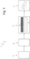
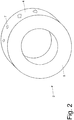
- the retreading plant 1 comprises a removal station 3, wherein the old worn tread (not shown) is mechanically removed from the pneumatic tyre 2, exposing an equatorial surface 4 (illustrated in figure 2 ) of a casing 5 of the pneumatic tyre 2.
- the retreading plant 1 comprises a skiving and filling station 6, wherein the equatorial surface 4 of the casing 5 is subjected to a skiving in order to remove any local damage; the skiving operation results in the formation on the equatorial surface 4 of the casing 5 of craters 7 (illustrated schematically in figure 2 ) of random and variable dimensions and positions which are subsequently filled with green rubber.
- the retreading plant 1 comprises a winding station 8 whereto the casing 5 is transferred at the end of the filling; within the winding station 8, an intermediate strip or cushion 9 of green rubber and a tread strip 10 (which may be green or more frequently pre-vulcanized) are wound about the casing 5.
- the retreading plant 1 comprises a vulcanization station 11, wherein the retreaded pneumatic tyre 2 (i.e., provided with the tread strip 10) is vulcanized, thereby ending the retreading process.
- the retreaded pneumatic tyre 2 i.e., provided with the tread strip 10.
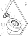
- the skiving and filling station 6 comprises a laser type profilometer 12 (i.e., a three-dimensional scanner), which is arranged in a fixed position in front of the equatorial surface 4 of the casing 5 in order to capture a three-dimensional profile of the equatorial surface 4.
- a laser type profilometer 12 i.e., a three-dimensional scanner
- the casing 5 is mounted on a motorized hub 13 that is suited to rotate the casing 5 around the longitudinal axis thereof and that is provided with an angular encoder 14 in order to measure in real time the angular position of the casing 5.
- a control unit 15 drives a motorized hub 13 in order to make the casing 5 complete one revolution (i.e., a rotation angle of 360°) with a stepwise movement (i.e., presenting motion phases interleaved with stationary phases); corresponding to predetermined intervals of the angular position of the casing 5 (for example every 0.5°, 1° or 2°) - the amplitude thereof depending upon the required resolution - the profilometer 12 measures a distance between each point on the equatorial surface 4, arranged on a line parallel to the longitudinal axis, and the profilometer 12, scanning the equatorial surface 4 from shoulder to shoulder.
- a laser beam emitted by the profilometer 12 is cyclically moved in order to scan the equatorial surface 4 from shoulder to shoulder for every halt in the stepwise rotation of the casing 5 driven by the motorized hub 13.
- the three-dimensional profile of the equatorial surface 4 of the casing 5 consists of a matrix that identifies each point on the equatorial surface 4 and provides the distance between each point on the equatorial surface 4 and the profilometer 12.
- the three-dimensional profile of the equatorial surface 4 of the casing 5 consists of a matrix d ( ⁇ i , x i ) that provides the distance d between the i-th point of the equatorial surface 4 and the profilometer 12, wherein the i-th point of the equatorial surface 4 is identified by the coordinate ⁇ i (indicating the angle of rotation of the casing 5 in relation to a reference angle at the i-th point) and x i (indicating the axial position of the i-th point between the two shoulders of the casing 5).
- the skiving and filling station 6 comprises an automatic skiving device 16 (i.e., controlled electronically), which is electronically controlled by the control unit 15 in order to remove that part of the rubber corresponding to each damaged area that has been previously identified and creating a corresponding crater 7.
- the automatic skiving device 16 comprises a tool 17 (interchangeable, as more fully described below), which is suited to remove the rubber of the casing 5 by means of mechanical abrasion (the tool 17 is normally a grinding wheel or milling cutter), and an electromechanical actuator 18 (schematically shown in figure 4 ) which is controlled by the control unit 15 and carries the tool 17 in order to move (typically by means of rototranslation on multiple axes) the tool 17.
- the electromechanical actuator 18 consists of a robotic arm having multiple degrees of freedom (preferably six) in order to allow the tool 17 to perform all possible machining operations on the casing 5.
- the electromechanical actuator 18 also supports a digital camera 19 that is suited to capture digital color images, it is arranged next to the tool 17 and is connected to the control unit 15.
- the camera 19 is preferably coupled to an illuminator (usually LED) which is suited to project a white light at the area framed by the camera 19; generally, but not necessarily, the illuminator is mounted on the electromechanical actuator 18 next to the camera 19 and is accessed only during those short periods necessary for the acquisition of a digital image by means of the camera 19.
- the skiving device 16 comprises a tool carrier 20, which is arranged next to the electromechanical actuator 18 in such a way as to allow the electromechanical actuator 18 to independently (automatically) change the tool 17; in other words, the electromechanical actuator 18 can deposit within the tool carrier 20 the tool 17 carried by the actuator 18 and can then withdraw a new tool 17 from the tool carrier 20.
- the skiving and filling station 6 comprises an automatic spraying device which is electronically controlled by the control unit 15 in order to apply cement (i.e., a liquid based on green and normal-heptane rubber or another organic solvent) to the equatorial surface 4 of the casing 5 corresponding to those craters 7 opened by the previous skiving operation performed by the skiving device 16; the function of the cement being applied to the equatorial surface 4 is to promote adhesion of the green rubber intended to fill the craters 7.
- cement i.e., a liquid based on green and normal-heptane rubber or another organic solvent
- control unit 15 drives the motorized hub 13 in order to make the casing 5 complete one revolution (i.e., a rotation angle of 360°); at predetermined intervals of the angular position of the casing 5 (for example every 2°, 5° or 10°) the amplitude thereof depending upon the required resolution, if necessary the spraying device is activated in order to apply the cement only at those craters 7 opened during the previous skiving operation.
- the skiving and filling station 6 comprises an automatic applicator device which is electronically controlled by the control unit 15 in order to apply green rubber to the equatorial surface 4 of the casing 5 at those craters 7 opened by the previous skiving operation performed by the skiving device 16; the function of the green rubber is to close the craters 7 in order to "equalize” (i.e. make uniform) the equatorial surface 4 of the casing 5 before the winding of the intermediate strip 9 of green rubber and of the tread strip 10 (green or pre-vulcanized).
- control unit 15 drives the motorized hub 13 in order to make the casing 5 complete one revolution (i.e., a rotation angle of 360°); at predetermined intervals of the angular position of the casing 5 (for example every 2°, 5° or 10°), the amplitude thereof depending upon the required resolution, if necessary the applicator device is activated in order to apply the green rubber to craters 7 opened in the previous skiving operation.
- the control unit 15 performs the acquisition of the three-dimensional profile of the equatorial surface 4 of the casing 5 by means of the combined use of the motorized hub 13 (that rotates the casing 5 step by step) and of the profilometer 12 (that scans the equatorial surface 4 of the casing 5 from shoulder to shoulder in order to determine the distance existing between the profilometer 12 and each point on the equatorial surface 4); once the control unit 15 has completed the acquisition of the three-dimensional profile of the equatorial surface 4 of the casing 5, the same control unit 15 determines the presence of any damage in the equatorial surface 4 of the casing 5 analyzing the three-dimensional profile of the equatorial surface 4 of the casing 5.
- the control unit 15 searches for the presence of discontinuities in the radial dimension of the equatorial surface 4 of the casing 5, i.e., the control unit 15 searches for areas where there is a localized variation in the radial dimension; the radial dimension is the distance exiting between the equatorial surface 4 of the casing 5 and the longitudinal axis of the pneumatic tyre 2 (i.e., it coincides with the radius of equatorial surface 4 of the casing 5 in relation to the longitudinal axis of the pneumatic tyre 2) and is complementary to the distance that exists between the equatorial surface 4 of the casing 5 and the profilometer 12 and is measured by the same profilometer 12 during the acquisition of the three-dimensional profile.
- the control unit 15 identifies as damage an area wherein the radial dimension (i.e., the radius) is significantly different from the average radial dimension (i.e., from the average radius).
- control unit 15 calculates both an average overall radial dimension (i.e., the entire equatorial surface 4 of the casing 5), and an average local radial dimension (for example, calculated within areas each having a width of 10-45°, i.e., that each extend to 2.7-12.5% of the entire equatorial surface 4).
- the control unit 15 searches for any points where the radial dimension significantly deviates (i.e., above a predetermined threshold) from the average radial dimension; the overall average radial dimension can be used in this comparison (i.e., extended over the entire equatorial surface 4 of the casing 5) and/or the local average radial dimension (i.e., limited to an area of the equatorial surface 4 of the casing 5). In this way, the control unit 15 searches for the presence of holes or crests in the equatorial surface 4 of the casing 5 and identifies such holes or crests as damage.
- the variation ⁇ i of the radial dimension of the i-th point is greater than the threshold value TH, then, in correspondence with the i-th point, a hole or a crest (therefore damage) can be identified on the equatorial surface 4 of the casing 5; in order for a hole or a crest (and therefore damage) to be truly identified, it is obviously necessary for a number of adjacent points to exhibit a significant radial dimension variation ⁇ i (i.e., greater than the threshold value TH).
- the minimum number of adjacent points that must exhibit the significant radial dimension variation ⁇ i in order to be able to identify damage is generally variable and constitutes a pre-settable threshold.
- the control unit 15 drives the skiving device 16 in order to perform the skiving of each point of damage.
- the control unit 15 preliminarily performs the recognition of the morphology (typology) of the damage by determining the salient characteristics of the damage (for example the average diameter, the extension, the average depth, the maximum depth) and by comparing the salient characteristics of the damage against a reference library (or a database) of damage in order to identify the closest damage of reference (i.e., the damage of reference that has the most similar morphology).
- the tool 17 to be used is then chosen from between those tools 17 available within the tool-carrier 20, and the kind of skiving operation to be performed is chosen (for example how wide and deep the skiving operation must be).
- the control unit 15 drives the motorized hub 13 in order to rotate the casing 5 in such a way as to arrange the damage in the optimal position in relation to the electromechanical actuator 18 (i.e., in the position wherein the electromechanical actuator 18 can most easily carry the tool 17 in order to operate on the damage), the control unit 15 then drives the electromechanical actuator 18 and the tool 17 in order to perform the skiving operation.
- the control unit 15 stops the tool 17 and drives the electromechanical actuator 18 such that the camera 19 frames the crater 7 that was generated by skiving the point of damage; at this point, the camera 19 takes (at least) a first digital color image of the crater 7 generated by the skiving of the damage.
- the first digital color image of the crater 7 generated by the skiving of the damage is analyzed by the control unit 15 in search of any traces of rust on the tread ply cords (if and when the tread plies are visible).
- the search for any traces of rust is performed by searching for the presence of different coloring stains on the tread ply cords; in particular, the first digital color image is searched for the presence of stains with more or less red coloring, i.e., the digital color image is searched for the presence of traces having a kind of red coloring: within the casing 4, there should only be black (typical of rubber) or shiny gray (typical of the tread ply cords that are normally made of steel) colorings, and then the presence of red colorings (i.e., colorings having a non-negligible red component) is therefore inevitably linked to the presence of rust.
- red colorings i.e., colorings having a non-negligible red component
- the operation of skiving the damage is considered to be concluded; however, if the analysis of the first digital color image of the crater 7 generated by the skiving of the damage indicates the presence of rust on the tread ply cords, then a second deeper skiving operation is performed, which will result in the partial removal of the tread plies.
- a second digital color image is captured of the crater 7 generated by the skiving of the damage and the presence of rust on the tread ply cords is again checked. If the analysis of the second digital color image of the crater 7 generated by the skiving of the damage does not show the presence of rust on the tread ply cords, then the operation of skiving the damage is considered to be concluded; however, if the analysis of the second digital color image of the crater 7 generated by the skiving of the damage indicates the presence of rust on the tread ply cords, then a third still deeper skiving operation is performed which will result in the further partial removal of the tread plies.
- a third digital color image is captured of the crater 7 generated by the skiving of the damage and the presence of rust on the tread ply cords is again checked. If the analysis of the third digital color image of the crater 7 generated by the skiving of the damage does not show the presence of rust on the tread ply cords, then the operation of skiving the damage is considered to be concluded; however, if the analysis of the third digital color image of the crater 7 generated by the skiving of the damage indicates the presence of rust on the tread ply cords, then the retreading process is halted and the casing 4, insofar as it is not suitable for retreading (i.e., it is too compromised to be retreaded), is discarded.
- the maximum number of skiving operations that are performed before deciding to discard a casing 4 is variable; the casing 4 may therefore be discarded after the first skiving operation, after the second skiving operation, after the fourth skiving operation, or after the fifth skiving operation.
- the skiving and filling station 6 described above has numerous advantages.
- the skiving and filling station 6 described above makes it possible to effectively and efficiently recognize damage present on the equatorial surface 4 of the casing 5; in other words, the damage present on the equatorial surface 4 of the casing 5 is effectively (i.e., without " false positives " that lead to the identification of simple surface stains as damage) and efficiently (i.e., without not-recognizing the damage actually present) identified.
- the skiving and filling station 6 described above makes it possible to effectively and efficiently recognize the presence of rust on the bottom of the crater 7 generated by the skiving of the damage; in other words, the rust present on the bottom of the crater 7 is effectively (i.e., without "false positives " that lead to the identification of other types of surface stains such as rust) and efficiently (i.e., without failing to recognize the rust actually present) identified.
- This result is obtained by virtue of the fact that the presence of rust is searched for in searching for the presence of red or similar coloring within a digital color image captured by the camera 19.
- skiving and filling station 6 is relatively simple and inexpensive to implement, insofar as from a construction point of view it only uses commercial components (i.e., readily available on the market) and from a computational point of view it requires substantially modest processing power.
Landscapes
- Engineering & Computer Science (AREA)
- Mechanical Engineering (AREA)
- Physics & Mathematics (AREA)
- General Physics & Mathematics (AREA)
- Tyre Moulding (AREA)
Claims (10)
- Verfahren zum Schälen der Äquatorialoberfläche (4) der Karkasse (5) eines Luftreifens (2) während eines Runderneuerungsprozesses des gleichen Luftreifens (2), wobei das Verfahren die Schritte umfasst:Entfernen der alten abgenutzten Lauffläche von dem Luftreifen (2), um die Äquatorialoberfläche (4) der Karkasse (5) des Luftreifens (2) freizulegen;elektronisches Identifizieren des Vorhandenseins und der Stelle eines beliebigen Schadens auf der Äquatorialoberfläche (4) der Karkasse (5); undSchälen der Äquatorialoberfläche (4) der Karkasse (5), wo Schaden vorliegt, mittels einer elektronisch gesteuerten automatischen Schälvorrichtung (16), die in Abhängigkeit von der Stelle des Schadens auf der Äquatorialoberfläche (4) der Karkasse (5) angetrieben wird, wodurch die Bildung von Kratern (7) auf der Äquatorialoberfläche (4) resultiert;wobei das Verfahren dadurch gekennzeichnet ist, dassder Schritt des elektronischen Identifizierens des Vorhandenseins und der Stelle eines Schadens auf der Äquatorialoberfläche (4) der Karkasse (5) vor dem Schälen der Äquatorialoberfläche (4) der Karkasse (5) die zusätzlichen Schritte umfasst:• Erfassen eines einzigen digitalen dreidimensionalen Profils der gesamten Äquatorialoberfläche (4) der Karkasse (5) mittels eines Profilometers (12) vom Lasertyp, das in einer festen Position vor der Äquatorialoberfläche (4) der Karkasse (5) angeordnet ist; und• Bestimmen des Vorhandenseins und der Stelle des Schadens auf der Äquatorialoberfläche (4) der Karkasse (5) durch Analysieren des digitalen dreidimensionalen Profils der Äquatorialoberfläche (4), das von dem Profilometer (12) vom Lasertyp erfasst wird;wobei der Schritt des Schälens der Äquatorialoberfläche (4) der Karkasse (5), wo es den Schaden gibt, die weiteren Schritte umfasst:• Führen des Werkzeugs (17) der automatischen Schälvorrichtung (16) zur Schadensstelle, um die Äquatorialoberfläche (4) der Karkasse (5) auszuhöhlen und dadurch einen entsprechenden Krater (7) zu erzeugen;• Erfassen eines ersten digitalen Farbbilds des Kraters (7), der durch Schälen des Schadens generiert wird, mittels der digitalen Farbkamera (19); und• Analysieren des ersten digitalen Farbbilds bei der Suche nach dem Vorhandensein von Rost im Inneren des Kraters (7).
- Verfahren nach Anspruch 1, wobei der Schritt des Erfassens des digitalen dreidimensionalen Profils der Äquatorialoberfläche (4) der Karkasse (5) die weiteren Schritte umfasst:Montieren der Karkasse (5) auf eine motorisierte Nabe (13), die geeignet ist, um die Karkasse (5) um die Längsachse davon herum zu rotieren und die mit einem Winkelgeber (14) bereitgestellt wird, um die Winkelposition der Karkasse (5) in Echtzeit zu messen;Anordnen des Profilometers (12) vom Lasertyp in einer festen Position vor der Äquatorialoberfläche (4) der Karkasse (5), die auf der Nabe (13) montiert ist;schrittweises Rotieren der Karkasse (5) vor dem Profilometer (12) vom Lasertyp; undAbtasten der Äquatorialoberfläche (4) von Schulter zu Schulter mittels des Profilometers (12) vom Lasertyp für jeden Halt bei der schrittweisen Rotation.
- Verfahren nach Anspruch 1 oder 2, wobei das digitale dreidimensionale Profil der Äquatorialoberfläche (4) der Karkasse (5) aus einer Matrix besteht, die jeden Punkt auf der Äquatorialoberfläche (4) identifiziert und den Abstand zwischen jedem Punkt auf der Äquatorialoberfläche (4) und dem Profilometer (12) vom Lasertyp bereitstellt.
- Verfahren nach Anspruch 1, 2 oder 3, wobei der Schritt des Bestimmens des Vorhandenseins und der Stelle von Schaden auf der Äquatorialoberfläche (4) der Karkasse (5) die weiteren Schritte umfasst:Berechnen einer mittleren radialen Abmessung der Äquatorialoberfläche (4) der Karkasse (5); undIdentifizieren des Schadens, der einem Bereich der Äquatorialoberfläche (4) entspricht, wobei sich die radiale Abmessung von der mittleren radialen Abmessung unterscheidet.
- Verfahren nach einem der Ansprüche 1 bis 4 und umfassend die weiteren Schritte:wenn es keinen Rost im Inneren des Kraters (7) gibt, Beenden des Schälvorgangs; oderwenn es Rost im Inneren des Kraters (7) gibt, den Krater mittels des Werkzeugs (17) weiter aushöhlen, mittels der digitalen Farbkamera (19) ein zweites digitales Farbbild des Kraters (7) erfassen und das zweite digitale Farbbild analysieren, um nach dem Vorhandensein von Rost im Inneren des Kraters (7) zu suchen.
- Verfahren nach Anspruch 5 und umfassend die weiteren Schritte:wenn es keinen Rost im Inneren des Kraters (7) gibt, Beenden des Schälvorgangs; oderwenn es Rost im Inneren des Kraters (7) gibt, den Krater (7) mittels des Werkzeugs (17) weiter aushöhlen, mittels der digitalen Farbkamera (19) ein drittes digitales Farbbild des Kraters (7) erfassen und das dritte digitale Farbbild analysieren, um nach dem Vorhandensein von Rost im Inneren des Kraters (7) zu suchen.
- Verfahren nach Anspruch 6 und umfassend die weiteren Schritte:wenn es keinen Rost im Inneren des Kraters (7) gibt, Beenden des Schälvorgangs; oderwenn es Rost im Inneren des Kraters (7) gibt, unterbrechen der Runderneuerung für den Luftreifen (2) und verwerfen des gleichen Luftreifens (2).
- Verfahren nach einem der Ansprüche 1 bis 7, wobei die Suche nach Spuren von Rost innerhalb eines digitalen Bilds bei der Suche innerhalb des gleichen digitalen Bilds nach der Anwesenheit von Spuren der Farbe Rot durchgeführt wird.
- Verfahren nach einem der Ansprüche 1 bis 8, wobei die automatische Schälvorrichtung (16) elektronisch gesteuert wird, um einen Teil des Kautschuks zu entfernen, wo sich jeweils Schaden befindet, und umfasst:das Werkzeug (17), das geeignet ist, den Kautschuk der Karkasse (5) mittels eines mechanischen Abriebs zu entfernen;einen elektromechanischen Aktuator (18), der das Werkzeug (17) führt und geeignet ist, das Werkzeug (17) zu bewegen; unddie digitale Kamera (19), die durch den elektromechanischen Aktuator (18) geführt wird und neben dem Werkzeug (17) angeordnet ist.
- Station (6) zum Schälen der Äquatorialoberfläche (4) der Karkasse (5) eines Luftreifens (2) während eines Runderneuerungsprozesses des gleichen Luftreifens (2); wobei die Station (6) umfasst:eine elektronische Steuerungseinheit (15) zum Identifizieren des Vorhandenseins und der Stelle eines beliebigen Schadens auf der Äquatorialoberfläche (4) der Karkasse (5); undeine elektronisch gesteuerte automatische Schälvorrichtung (16), die ein Werkzeug (17) umfasst und die von der Steuereinheit (15) in Abhängigkeit von der Stelle des Schadens auf der Äquatorialoberfläche (4) der Karkasse (5) zum Schälen der Äquatorialoberfläche (4) der Karkasse (5), wo es resultierend aus der Bildung von Kratern (7) Schaden auf der Äquatorialoberfläche (4) gibt, angetrieben wird;wobei die automatische Schälvorrichtung (16) einen elektromechanischen Aktuator (18) umfasst, der von der Steuereinheit (15) gesteuert wird und das Werkzeug (17) führt, um das Werkzeug (17) zu bewegen;wobei die Station (6) dadurch gekennzeichnet ist, dass:ein Profilometer (12) vom Lasertyp in einer festen Position vor der Äquatorialoberfläche (4) der Karkasse (5) zum Erfassen eines einzigen digitalen dreidimensionalen Profils der Äquatorialoberfläche (4) der Karkasse (5) vor dem Schälen der Äquatorialoberfläche (4) der Karkasse (5) angeordnet ist;die Steuereinheit (15) das Vorhandensein und die Stelle eines Schadens auf der Äquatorialoberfläche(4) der Karkasse (5) durch Analysieren des digitalen dreidimensionalen Profils der Äquatorialoberfläche (4), das von dem Profilometer (12) vom Lasertyp erfasst wird, bestimmt;der elektromechanische Aktuator (18) das Werkzeug (17) zum Schadenspunkt führt, um die Äquatorialoberfläche (4) der Karkasse (5) auszuhöhlen und dadurch einen entsprechenden Krater (7) zu erzeugen;eine durch den elektromechanischen Aktuator (18) neben dem Werkzeug (17) getragene und mit der Steuereinheit (15) verbundene digitale Kamera (19) ein digitales Farbbild des Kraters (7), generiert durch Schälen, erfasst; unddie Steuereinheit (15) das digitale Farbbild bei der Suche nach dem Vorhandensein von Rost im Inneren des Kraters (7) analysiert.
Applications Claiming Priority (2)
| Application Number | Priority Date | Filing Date | Title |
|---|---|---|---|
| IT102016000123639A IT201600123639A1 (it) | 2016-12-06 | 2016-12-06 | Metodo e stazione per la ripulitura della superficie laterale della carcassa di un pneumatico durante un processo di ricostruzione del pneumatico stesso |
| PCT/EP2017/081571 WO2018104332A1 (en) | 2016-12-06 | 2017-12-05 | Method and station for the skiving of a tyre casing during retreading |
Publications (2)
| Publication Number | Publication Date |
|---|---|
| EP3551443A1 EP3551443A1 (de) | 2019-10-16 |
| EP3551443B1 true EP3551443B1 (de) | 2020-07-22 |
Family
ID=58402061
Family Applications (1)
| Application Number | Title | Priority Date | Filing Date |
|---|---|---|---|
| EP17808933.0A Active EP3551443B1 (de) | 2016-12-06 | 2017-12-05 | Verfahren und station zum ausschärfen einer reifenkarkasse während der runderneuerung |
Country Status (4)
| Country | Link |
|---|---|
| US (1) | US11472142B2 (de) |
| EP (1) | EP3551443B1 (de) |
| IT (1) | IT201600123639A1 (de) |
| WO (1) | WO2018104332A1 (de) |
Cited By (4)
| Publication number | Priority date | Publication date | Assignee | Title |
|---|---|---|---|---|
| EP4166310A1 (de) | 2021-10-13 | 2023-04-19 | Brandvulc Tyres Limited | Verfahren und vorrichtung zum präparieren der oberfläche der karkasse eines fahrzeugluftreifens im zuge einer runderneuerung desselben |
| WO2024194037A1 (fr) | 2023-03-21 | 2024-09-26 | Compagnie Generale Des Etablissements Michelin | Système et procédé de nettoyage automatique de fond de sculpture de pneumatique |
| FR3161145A1 (fr) | 2024-04-16 | 2025-10-17 | Compagnie Generale Des Etablissements Michelin | Système de réparation automatique de dommages superficiels de pneumatique par robot et capteur 3D de vision |
| FR3161144A1 (fr) | 2024-04-16 | 2025-10-17 | Compagnie Generale Des Etablissements Michelin | Système de réparation automatique de dommages superficiels de pneumatique par robot et capteur 3D de vision |
Families Citing this family (9)
| Publication number | Priority date | Publication date | Assignee | Title |
|---|---|---|---|---|
| IT201900010608A1 (it) * | 2019-07-01 | 2021-01-01 | Comet S R L | Macchina per la lavorazione di battistrada |
| IT201900010605A1 (it) * | 2019-07-01 | 2021-01-01 | Comet S R L | Macchina per la lavorazione di battistrada |
| JP7700494B2 (ja) * | 2021-04-09 | 2025-07-01 | 住友ゴム工業株式会社 | タイヤ状態判定システム、タイヤ状態判定装置、タイヤ状態判定方法、及びプログラム |
| EP4472833A1 (de) | 2022-02-03 | 2024-12-11 | Bridgestone Bandag, LLC | Automatisches füllsystem für fliegende fliegende körper |
| CN115319551B (zh) * | 2022-06-30 | 2024-10-01 | 山东玲珑轮胎股份有限公司 | 一种轮胎打磨装置 |
| EP4481361A1 (de) * | 2023-06-23 | 2024-12-25 | Bridgestone Europe NV/SA | Detectieren von defekten von einer oberfläche einer buffreifenkarkasse |
| EP4480687A1 (de) * | 2023-06-23 | 2024-12-25 | Bridgestone Europe NV/SA | Entfernung von defekten von einer oberfläche einer aufgerauhten reifenkarkasse |
| EP4480686A1 (de) * | 2023-06-23 | 2024-12-25 | Bridgestone Europe NV/SA | Entfernung von defekten von einer oberfläche einer aufgerauhten reifenkarkasse |
| FR3151780B1 (fr) * | 2023-08-04 | 2025-07-11 | Michelin & Cie | Procédé d’usinage de la couche externe d’un bandage au cours duquel on adapte la trajectoire de coupe en fonction de l’orientation des fils de renfort qui sont situés sous ladite couche externe |
Family Cites Families (13)
| Publication number | Priority date | Publication date | Assignee | Title |
|---|---|---|---|---|
| JPH04341835A (ja) * | 1991-05-17 | 1992-11-27 | Bridgestone Corp | 更生タイヤ用スカイブ装置 |
| FR2714070A1 (fr) * | 1993-12-20 | 1995-06-23 | Michelin & Cie | Procédé et dispositif de traitement avant collage de surfaces caoutchoutiques vulcanisées. |
| US6899778B1 (en) * | 2000-01-27 | 2005-05-31 | Bandag Incorporated | Method and apparatus for preparing tire tread for a retread tire |
| US6758931B1 (en) * | 2000-01-27 | 2004-07-06 | Bandag, Incorporated | Method and apparatus for applying tire tread for a retread tire |
| EP1120233A3 (de) * | 2000-01-27 | 2001-10-24 | Bandag Incorporated | Verfahren un Vorrichtung zum Runderneuern von Reifen |
| JP2008128790A (ja) * | 2006-11-20 | 2008-06-05 | Bridgestone Corp | 損傷検出方法、タイヤ更生方法およびタイヤ更生装置 |
| US8282442B2 (en) * | 2007-09-28 | 2012-10-09 | Michelin Recherche Et Technique S.A. | Correction of crown layer variance during retreading |
| IT1393544B1 (it) * | 2009-03-31 | 2012-04-27 | Cappuccini | Procedimento e macchina per l'individuazione e la lavorazione di difetti su pneumatici usati. |
| US8803673B2 (en) * | 2009-06-29 | 2014-08-12 | Michelin Recherche Et Technique S.A. | System and method for evaluating surface finish of tire retread |
| IT1394907B1 (it) * | 2009-07-22 | 2012-07-20 | Bridgestone Corp | Metodo ed impianto di ricostruzione di un pneumatico |
| MX2014007222A (es) * | 2011-12-16 | 2015-03-19 | Alan Erdman | Dispositivo y un metodo para reencauchar neumaticos. |
| BR112017024989A2 (pt) * | 2015-05-26 | 2018-07-31 | Bridgestone Bandag, Llc | molde para produzir a banda de rodagem de um pneu, e, prensa de cura para formar uma banda de rodagem de um pneu. |
| US11247424B1 (en) * | 2016-12-13 | 2022-02-15 | Bridgestone Americas Tire Operations, Llc | Methods for retreading tires |
-
2016
- 2016-12-06 IT IT102016000123639A patent/IT201600123639A1/it unknown
-
2017
- 2017-12-05 EP EP17808933.0A patent/EP3551443B1/de active Active
- 2017-12-05 US US16/464,825 patent/US11472142B2/en active Active
- 2017-12-05 WO PCT/EP2017/081571 patent/WO2018104332A1/en not_active Ceased
Non-Patent Citations (1)
| Title |
|---|
| None * |
Cited By (7)
| Publication number | Priority date | Publication date | Assignee | Title |
|---|---|---|---|---|
| EP4166310A1 (de) | 2021-10-13 | 2023-04-19 | Brandvulc Tyres Limited | Verfahren und vorrichtung zum präparieren der oberfläche der karkasse eines fahrzeugluftreifens im zuge einer runderneuerung desselben |
| WO2024194037A1 (fr) | 2023-03-21 | 2024-09-26 | Compagnie Generale Des Etablissements Michelin | Système et procédé de nettoyage automatique de fond de sculpture de pneumatique |
| FR3146830A1 (fr) | 2023-03-21 | 2024-09-27 | Compagnie Generale Des Etablissements Michelin | Système et procédé de nettoyage automatique de fond de sculpture de pneumatique |
| FR3161145A1 (fr) | 2024-04-16 | 2025-10-17 | Compagnie Generale Des Etablissements Michelin | Système de réparation automatique de dommages superficiels de pneumatique par robot et capteur 3D de vision |
| FR3161144A1 (fr) | 2024-04-16 | 2025-10-17 | Compagnie Generale Des Etablissements Michelin | Système de réparation automatique de dommages superficiels de pneumatique par robot et capteur 3D de vision |
| WO2025219138A1 (fr) | 2024-04-16 | 2025-10-23 | Compagnie Generale Des Etablissements Michelin | Système de réparation automatique de dommages superficiels de pneumatique par robot et capteur 3d de vision |
| WO2025219140A1 (fr) | 2024-04-16 | 2025-10-23 | Compagnie Generale Des Etablissements Michelin | Système de réparation automatique de dommages superficiels de pneumatique par robot et capteur 3d de vision |
Also Published As
| Publication number | Publication date |
|---|---|
| US11472142B2 (en) | 2022-10-18 |
| IT201600123639A1 (it) | 2018-06-06 |
| EP3551443A1 (de) | 2019-10-16 |
| WO2018104332A1 (en) | 2018-06-14 |
| US20190283354A1 (en) | 2019-09-19 |
Similar Documents
| Publication | Publication Date | Title |
|---|---|---|
| EP3551443B1 (de) | Verfahren und station zum ausschärfen einer reifenkarkasse während der runderneuerung | |
| EP3583397B1 (de) | Vorrichtung zur erkennung und überprüfung von defekten eines reifens am ende eines produktionsprozesses | |
| JP6789292B2 (ja) | タイヤを検査する方法および装置 | |
| EP3087366B1 (de) | Verfahren und vorrichtung zur erkennung von defekten auf reifen in einem reifenherstellungsverfahren | |
| US10006836B2 (en) | Method and apparatus for detecting defects on tyres in a tyre production process | |
| EP2880415B1 (de) | Verfahren zur segmentierung der fläche eines reifens und nach diesem verfahren betriebene vorrichtung | |
| JP6732027B2 (ja) | タイヤを検査するための装置および方法 | |
| CN109693140B (zh) | 一种智能化柔性生产线及其工作方法 | |
| EP2456612B1 (de) | Reifenrunderneuerungsverfahren und vorrichtung. | |
| EP2414153B1 (de) | Verfahren und maschine zur identifikation und bearbeitung von defekten an altreifen | |
| US20170173907A1 (en) | Self correcting tire buffing apparatus and method | |
| JP2008128790A (ja) | 損傷検出方法、タイヤ更生方法およびタイヤ更生装置 | |
| WO2024194037A1 (fr) | Système et procédé de nettoyage automatique de fond de sculpture de pneumatique | |
| KR101983898B1 (ko) | 그린타이어 가류 방향 제어 장치 | |
| JP4799280B2 (ja) | タイヤ更生用バフ装置およびそれを用いたタイヤの更生方法 | |
| WO2025219140A1 (fr) | Système de réparation automatique de dommages superficiels de pneumatique par robot et capteur 3d de vision | |
| WO2025219138A1 (fr) | Système de réparation automatique de dommages superficiels de pneumatique par robot et capteur 3d de vision | |
| JP6848284B2 (ja) | スピュー特定方法、ビード部の検査方法、およびビード部の検査装置 | |
| EP4644138A2 (de) | Anwendung von ki-basierter bildverarbeitung bei der wartung von fahrzeugrädern | |
| US20170148146A1 (en) | Tire image rectifying method | |
| WO2023150445A1 (en) | Auto skive filling system | |
| CN121347533A (zh) | 一种轮毂烤漆质量的视觉检测系统 | |
| ITMI20130611A1 (it) | Macchina per scolpire il battistrada di pneumatici ricostruiti. |
Legal Events
| Date | Code | Title | Description |
|---|---|---|---|
| STAA | Information on the status of an ep patent application or granted ep patent |
Free format text: STATUS: UNKNOWN |
|
| STAA | Information on the status of an ep patent application or granted ep patent |
Free format text: STATUS: THE INTERNATIONAL PUBLICATION HAS BEEN MADE |
|
| PUAI | Public reference made under article 153(3) epc to a published international application that has entered the european phase |
Free format text: ORIGINAL CODE: 0009012 |
|
| STAA | Information on the status of an ep patent application or granted ep patent |
Free format text: STATUS: REQUEST FOR EXAMINATION WAS MADE |
|
| 17P | Request for examination filed |
Effective date: 20190701 |
|
| AK | Designated contracting states |
Kind code of ref document: A1 Designated state(s): AL AT BE BG CH CY CZ DE DK EE ES FI FR GB GR HR HU IE IS IT LI LT LU LV MC MK MT NL NO PL PT RO RS SE SI SK SM TR |
|
| AX | Request for extension of the european patent |
Extension state: BA ME |
|
| GRAP | Despatch of communication of intention to grant a patent |
Free format text: ORIGINAL CODE: EPIDOSNIGR1 |
|
| STAA | Information on the status of an ep patent application or granted ep patent |
Free format text: STATUS: GRANT OF PATENT IS INTENDED |
|
| DAV | Request for validation of the european patent (deleted) | ||
| DAX | Request for extension of the european patent (deleted) | ||
| INTG | Intention to grant announced |
Effective date: 20200213 |
|
| GRAS | Grant fee paid |
Free format text: ORIGINAL CODE: EPIDOSNIGR3 |
|
| GRAA | (expected) grant |
Free format text: ORIGINAL CODE: 0009210 |
|
| STAA | Information on the status of an ep patent application or granted ep patent |
Free format text: STATUS: THE PATENT HAS BEEN GRANTED |
|
| AK | Designated contracting states |
Kind code of ref document: B1 Designated state(s): AL AT BE BG CH CY CZ DE DK EE ES FI FR GB GR HR HU IE IS IT LI LT LU LV MC MK MT NL NO PL PT RO RS SE SI SK SM TR |
|
| REG | Reference to a national code |
Ref country code: GB Ref legal event code: FG4D |
|
| REG | Reference to a national code |
Ref country code: CH Ref legal event code: EP |
|
| REG | Reference to a national code |
Ref country code: DE Ref legal event code: R096 Ref document number: 602017020328 Country of ref document: DE |
|
| REG | Reference to a national code |
Ref country code: AT Ref legal event code: REF Ref document number: 1293009 Country of ref document: AT Kind code of ref document: T Effective date: 20200815 |
|
| REG | Reference to a national code |
Ref country code: IE Ref legal event code: FG4D |
|
| REG | Reference to a national code |
Ref country code: LT Ref legal event code: MG4D |
|
| REG | Reference to a national code |
Ref country code: AT Ref legal event code: MK05 Ref document number: 1293009 Country of ref document: AT Kind code of ref document: T Effective date: 20200722 |
|
| PG25 | Lapsed in a contracting state [announced via postgrant information from national office to epo] |
Ref country code: GR Free format text: LAPSE BECAUSE OF FAILURE TO SUBMIT A TRANSLATION OF THE DESCRIPTION OR TO PAY THE FEE WITHIN THE PRESCRIBED TIME-LIMIT Effective date: 20201023 Ref country code: FI Free format text: LAPSE BECAUSE OF FAILURE TO SUBMIT A TRANSLATION OF THE DESCRIPTION OR TO PAY THE FEE WITHIN THE PRESCRIBED TIME-LIMIT Effective date: 20200722 Ref country code: NO Free format text: LAPSE BECAUSE OF FAILURE TO SUBMIT A TRANSLATION OF THE DESCRIPTION OR TO PAY THE FEE WITHIN THE PRESCRIBED TIME-LIMIT Effective date: 20201022 Ref country code: AT Free format text: LAPSE BECAUSE OF FAILURE TO SUBMIT A TRANSLATION OF THE DESCRIPTION OR TO PAY THE FEE WITHIN THE PRESCRIBED TIME-LIMIT Effective date: 20200722 Ref country code: SE Free format text: LAPSE BECAUSE OF FAILURE TO SUBMIT A TRANSLATION OF THE DESCRIPTION OR TO PAY THE FEE WITHIN THE PRESCRIBED TIME-LIMIT Effective date: 20200722 Ref country code: HR Free format text: LAPSE BECAUSE OF FAILURE TO SUBMIT A TRANSLATION OF THE DESCRIPTION OR TO PAY THE FEE WITHIN THE PRESCRIBED TIME-LIMIT Effective date: 20200722 Ref country code: ES Free format text: LAPSE BECAUSE OF FAILURE TO SUBMIT A TRANSLATION OF THE DESCRIPTION OR TO PAY THE FEE WITHIN THE PRESCRIBED TIME-LIMIT Effective date: 20200722 Ref country code: LT Free format text: LAPSE BECAUSE OF FAILURE TO SUBMIT A TRANSLATION OF THE DESCRIPTION OR TO PAY THE FEE WITHIN THE PRESCRIBED TIME-LIMIT Effective date: 20200722 Ref country code: PT Free format text: LAPSE BECAUSE OF FAILURE TO SUBMIT A TRANSLATION OF THE DESCRIPTION OR TO PAY THE FEE WITHIN THE PRESCRIBED TIME-LIMIT Effective date: 20201123 Ref country code: BG Free format text: LAPSE BECAUSE OF FAILURE TO SUBMIT A TRANSLATION OF THE DESCRIPTION OR TO PAY THE FEE WITHIN THE PRESCRIBED TIME-LIMIT Effective date: 20201022 |
|
| PG25 | Lapsed in a contracting state [announced via postgrant information from national office to epo] |
Ref country code: IS Free format text: LAPSE BECAUSE OF FAILURE TO SUBMIT A TRANSLATION OF THE DESCRIPTION OR TO PAY THE FEE WITHIN THE PRESCRIBED TIME-LIMIT Effective date: 20201122 Ref country code: LV Free format text: LAPSE BECAUSE OF FAILURE TO SUBMIT A TRANSLATION OF THE DESCRIPTION OR TO PAY THE FEE WITHIN THE PRESCRIBED TIME-LIMIT Effective date: 20200722 Ref country code: RS Free format text: LAPSE BECAUSE OF FAILURE TO SUBMIT A TRANSLATION OF THE DESCRIPTION OR TO PAY THE FEE WITHIN THE PRESCRIBED TIME-LIMIT Effective date: 20200722 Ref country code: PL Free format text: LAPSE BECAUSE OF FAILURE TO SUBMIT A TRANSLATION OF THE DESCRIPTION OR TO PAY THE FEE WITHIN THE PRESCRIBED TIME-LIMIT Effective date: 20200722 |
|
| PG25 | Lapsed in a contracting state [announced via postgrant information from national office to epo] |
Ref country code: NL Free format text: LAPSE BECAUSE OF FAILURE TO SUBMIT A TRANSLATION OF THE DESCRIPTION OR TO PAY THE FEE WITHIN THE PRESCRIBED TIME-LIMIT Effective date: 20200722 |
|
| REG | Reference to a national code |
Ref country code: DE Ref legal event code: R097 Ref document number: 602017020328 Country of ref document: DE |
|
| PG25 | Lapsed in a contracting state [announced via postgrant information from national office to epo] |
Ref country code: IT Free format text: LAPSE BECAUSE OF FAILURE TO SUBMIT A TRANSLATION OF THE DESCRIPTION OR TO PAY THE FEE WITHIN THE PRESCRIBED TIME-LIMIT Effective date: 20200722 Ref country code: SM Free format text: LAPSE BECAUSE OF FAILURE TO SUBMIT A TRANSLATION OF THE DESCRIPTION OR TO PAY THE FEE WITHIN THE PRESCRIBED TIME-LIMIT Effective date: 20200722 Ref country code: EE Free format text: LAPSE BECAUSE OF FAILURE TO SUBMIT A TRANSLATION OF THE DESCRIPTION OR TO PAY THE FEE WITHIN THE PRESCRIBED TIME-LIMIT Effective date: 20200722 Ref country code: RO Free format text: LAPSE BECAUSE OF FAILURE TO SUBMIT A TRANSLATION OF THE DESCRIPTION OR TO PAY THE FEE WITHIN THE PRESCRIBED TIME-LIMIT Effective date: 20200722 Ref country code: DK Free format text: LAPSE BECAUSE OF FAILURE TO SUBMIT A TRANSLATION OF THE DESCRIPTION OR TO PAY THE FEE WITHIN THE PRESCRIBED TIME-LIMIT Effective date: 20200722 Ref country code: CZ Free format text: LAPSE BECAUSE OF FAILURE TO SUBMIT A TRANSLATION OF THE DESCRIPTION OR TO PAY THE FEE WITHIN THE PRESCRIBED TIME-LIMIT Effective date: 20200722 |
|
| PLBE | No opposition filed within time limit |
Free format text: ORIGINAL CODE: 0009261 |
|
| STAA | Information on the status of an ep patent application or granted ep patent |
Free format text: STATUS: NO OPPOSITION FILED WITHIN TIME LIMIT |
|
| PG25 | Lapsed in a contracting state [announced via postgrant information from national office to epo] |
Ref country code: AL Free format text: LAPSE BECAUSE OF FAILURE TO SUBMIT A TRANSLATION OF THE DESCRIPTION OR TO PAY THE FEE WITHIN THE PRESCRIBED TIME-LIMIT Effective date: 20200722 |
|
| 26N | No opposition filed |
Effective date: 20210423 |
|
| PG25 | Lapsed in a contracting state [announced via postgrant information from national office to epo] |
Ref country code: SK Free format text: LAPSE BECAUSE OF FAILURE TO SUBMIT A TRANSLATION OF THE DESCRIPTION OR TO PAY THE FEE WITHIN THE PRESCRIBED TIME-LIMIT Effective date: 20200722 |
|
| REG | Reference to a national code |
Ref country code: CH Ref legal event code: PL |
|
| PG25 | Lapsed in a contracting state [announced via postgrant information from national office to epo] |
Ref country code: SI Free format text: LAPSE BECAUSE OF FAILURE TO SUBMIT A TRANSLATION OF THE DESCRIPTION OR TO PAY THE FEE WITHIN THE PRESCRIBED TIME-LIMIT Effective date: 20200722 Ref country code: MC Free format text: LAPSE BECAUSE OF FAILURE TO SUBMIT A TRANSLATION OF THE DESCRIPTION OR TO PAY THE FEE WITHIN THE PRESCRIBED TIME-LIMIT Effective date: 20200722 |
|
| REG | Reference to a national code |
Ref country code: BE Ref legal event code: MM Effective date: 20201231 |
|
| REG | Reference to a national code |
Ref country code: NL Ref legal event code: MP Effective date: 20200722 |
|
| PG25 | Lapsed in a contracting state [announced via postgrant information from national office to epo] |
Ref country code: LU Free format text: LAPSE BECAUSE OF NON-PAYMENT OF DUE FEES Effective date: 20201205 Ref country code: IE Free format text: LAPSE BECAUSE OF NON-PAYMENT OF DUE FEES Effective date: 20201205 |
|
| PG25 | Lapsed in a contracting state [announced via postgrant information from national office to epo] |
Ref country code: CH Free format text: LAPSE BECAUSE OF NON-PAYMENT OF DUE FEES Effective date: 20201231 Ref country code: LI Free format text: LAPSE BECAUSE OF NON-PAYMENT OF DUE FEES Effective date: 20201231 |
|
| PG25 | Lapsed in a contracting state [announced via postgrant information from national office to epo] |
Ref country code: MT Free format text: LAPSE BECAUSE OF FAILURE TO SUBMIT A TRANSLATION OF THE DESCRIPTION OR TO PAY THE FEE WITHIN THE PRESCRIBED TIME-LIMIT Effective date: 20200722 Ref country code: CY Free format text: LAPSE BECAUSE OF FAILURE TO SUBMIT A TRANSLATION OF THE DESCRIPTION OR TO PAY THE FEE WITHIN THE PRESCRIBED TIME-LIMIT Effective date: 20200722 |
|
| PG25 | Lapsed in a contracting state [announced via postgrant information from national office to epo] |
Ref country code: MK Free format text: LAPSE BECAUSE OF FAILURE TO SUBMIT A TRANSLATION OF THE DESCRIPTION OR TO PAY THE FEE WITHIN THE PRESCRIBED TIME-LIMIT Effective date: 20200722 |
|
| PG25 | Lapsed in a contracting state [announced via postgrant information from national office to epo] |
Ref country code: BE Free format text: LAPSE BECAUSE OF NON-PAYMENT OF DUE FEES Effective date: 20201231 |
|
| P01 | Opt-out of the competence of the unified patent court (upc) registered |
Effective date: 20230511 |
|
| PGFP | Annual fee paid to national office [announced via postgrant information from national office to epo] |
Ref country code: DE Payment date: 20251126 Year of fee payment: 9 |
|
| PGFP | Annual fee paid to national office [announced via postgrant information from national office to epo] |
Ref country code: GB Payment date: 20251119 Year of fee payment: 9 |
|
| PGFP | Annual fee paid to national office [announced via postgrant information from national office to epo] |
Ref country code: FR Payment date: 20251120 Year of fee payment: 9 |
|
| PGFP | Annual fee paid to national office [announced via postgrant information from national office to epo] |
Ref country code: TR Payment date: 20251126 Year of fee payment: 9 |