EP3551144B1 - Apparatur zum strahlungsschutz der augen - Google Patents
Apparatur zum strahlungsschutz der augen Download PDFInfo
- Publication number
- EP3551144B1 EP3551144B1 EP17837861.8A EP17837861A EP3551144B1 EP 3551144 B1 EP3551144 B1 EP 3551144B1 EP 17837861 A EP17837861 A EP 17837861A EP 3551144 B1 EP3551144 B1 EP 3551144B1
- Authority
- EP
- European Patent Office
- Prior art keywords
- eyes
- head
- wearer
- shell
- shield
- Prior art date
- Legal status (The legal status is an assumption and is not a legal conclusion. Google has not performed a legal analysis and makes no representation as to the accuracy of the status listed.)
- Active
Links
- 230000005855 radiation Effects 0.000 title claims description 33
- 210000003128 head Anatomy 0.000 claims description 36
- 230000003287 optical effect Effects 0.000 claims description 16
- 239000000463 material Substances 0.000 claims description 14
- 230000001681 protective effect Effects 0.000 claims description 10
- 230000005865 ionizing radiation Effects 0.000 claims description 5
- 230000000007 visual effect Effects 0.000 claims 8
- 239000013078 crystal Substances 0.000 claims 1
- 210000000695 crystalline len Anatomy 0.000 claims 1
- 239000011521 glass Substances 0.000 description 4
- 238000010276 construction Methods 0.000 description 3
- 230000003667 anti-reflective effect Effects 0.000 description 2
- 230000005540 biological transmission Effects 0.000 description 2
- 230000036772 blood pressure Effects 0.000 description 2
- 238000001514 detection method Methods 0.000 description 2
- 239000005355 lead glass Substances 0.000 description 2
- 238000011282 treatment Methods 0.000 description 2
- 238000003466 welding Methods 0.000 description 2
- 208000002177 Cataract Diseases 0.000 description 1
- 208000029091 Refraction disease Diseases 0.000 description 1
- 230000006978 adaptation Effects 0.000 description 1
- 229910052782 aluminium Inorganic materials 0.000 description 1
- XAGFODPZIPBFFR-UHFFFAOYSA-N aluminium Chemical compound [Al] XAGFODPZIPBFFR-UHFFFAOYSA-N 0.000 description 1
- 230000004430 ametropia Effects 0.000 description 1
- 210000004556 brain Anatomy 0.000 description 1
- 239000011248 coating agent Substances 0.000 description 1
- 238000000576 coating method Methods 0.000 description 1
- 238000004891 communication Methods 0.000 description 1
- 230000000052 comparative effect Effects 0.000 description 1
- 231100000040 eye damage Toxicity 0.000 description 1
- 229910052751 metal Inorganic materials 0.000 description 1
- 239000002184 metal Substances 0.000 description 1
- 238000000034 method Methods 0.000 description 1
- 238000002493 microarray Methods 0.000 description 1
- 210000000056 organ Anatomy 0.000 description 1
- 230000000149 penetrating effect Effects 0.000 description 1
- 208000014733 refractive error Diseases 0.000 description 1
- 239000013585 weight reducing agent Substances 0.000 description 1
Images

Classifications
-
- A—HUMAN NECESSITIES
- A61—MEDICAL OR VETERINARY SCIENCE; HYGIENE
- A61F—FILTERS IMPLANTABLE INTO BLOOD VESSELS; PROSTHESES; DEVICES PROVIDING PATENCY TO, OR PREVENTING COLLAPSING OF, TUBULAR STRUCTURES OF THE BODY, e.g. STENTS; ORTHOPAEDIC, NURSING OR CONTRACEPTIVE DEVICES; FOMENTATION; TREATMENT OR PROTECTION OF EYES OR EARS; BANDAGES, DRESSINGS OR ABSORBENT PADS; FIRST-AID KITS
- A61F9/00—Methods or devices for treatment of the eyes; Devices for putting-in contact lenses; Devices to correct squinting; Apparatus to guide the blind; Protective devices for the eyes, carried on the body or in the hand
- A61F9/02—Goggles
- A61F9/022—Use of special optical filters, e.g. multiple layers, filters for protection against laser light or light from nuclear explosions, screens with different filter properties on different parts of the screen; Rotating slit-discs
-
- A—HUMAN NECESSITIES
- A61—MEDICAL OR VETERINARY SCIENCE; HYGIENE
- A61B—DIAGNOSIS; SURGERY; IDENTIFICATION
- A61B6/00—Apparatus for radiation diagnosis, e.g. combined with radiation therapy equipment
- A61B6/10—Application or adaptation of safety means
- A61B6/107—Protection against radiation, e.g. shielding
-
- A—HUMAN NECESSITIES
- A61—MEDICAL OR VETERINARY SCIENCE; HYGIENE
- A61F—FILTERS IMPLANTABLE INTO BLOOD VESSELS; PROSTHESES; DEVICES PROVIDING PATENCY TO, OR PREVENTING COLLAPSING OF, TUBULAR STRUCTURES OF THE BODY, e.g. STENTS; ORTHOPAEDIC, NURSING OR CONTRACEPTIVE DEVICES; FOMENTATION; TREATMENT OR PROTECTION OF EYES OR EARS; BANDAGES, DRESSINGS OR ABSORBENT PADS; FIRST-AID KITS
- A61F9/00—Methods or devices for treatment of the eyes; Devices for putting-in contact lenses; Devices to correct squinting; Apparatus to guide the blind; Protective devices for the eyes, carried on the body or in the hand
- A61F9/02—Goggles
- A61F9/027—Straps; Buckles; Attachment of headbands
-
- G—PHYSICS
- G02—OPTICS
- G02B—OPTICAL ELEMENTS, SYSTEMS OR APPARATUS
- G02B27/00—Optical systems or apparatus not provided for by any of the groups G02B1/00 - G02B26/00, G02B30/00
- G02B27/01—Head-up displays
- G02B27/017—Head mounted
- G02B27/0172—Head mounted characterised by optical features
-
- H—ELECTRICITY
- H04—ELECTRIC COMMUNICATION TECHNIQUE
- H04N—PICTORIAL COMMUNICATION, e.g. TELEVISION
- H04N13/00—Stereoscopic video systems; Multi-view video systems; Details thereof
- H04N13/10—Processing, recording or transmission of stereoscopic or multi-view image signals
- H04N13/189—Recording image signals; Reproducing recorded image signals
-
- H—ELECTRICITY
- H04—ELECTRIC COMMUNICATION TECHNIQUE
- H04N—PICTORIAL COMMUNICATION, e.g. TELEVISION
- H04N13/00—Stereoscopic video systems; Multi-view video systems; Details thereof
- H04N13/20—Image signal generators
- H04N13/204—Image signal generators using stereoscopic image cameras
- H04N13/239—Image signal generators using stereoscopic image cameras using two 2D image sensors having a relative position equal to or related to the interocular distance
-
- H—ELECTRICITY
- H04—ELECTRIC COMMUNICATION TECHNIQUE
- H04N—PICTORIAL COMMUNICATION, e.g. TELEVISION
- H04N13/00—Stereoscopic video systems; Multi-view video systems; Details thereof
- H04N13/30—Image reproducers
- H04N13/332—Displays for viewing with the aid of special glasses or head-mounted displays [HMD]
- H04N13/344—Displays for viewing with the aid of special glasses or head-mounted displays [HMD] with head-mounted left-right displays
-
- G—PHYSICS
- G02—OPTICS
- G02B—OPTICAL ELEMENTS, SYSTEMS OR APPARATUS
- G02B27/00—Optical systems or apparatus not provided for by any of the groups G02B1/00 - G02B26/00, G02B30/00
- G02B27/01—Head-up displays
- G02B27/0101—Head-up displays characterised by optical features
- G02B2027/0132—Head-up displays characterised by optical features comprising binocular systems
- G02B2027/0134—Head-up displays characterised by optical features comprising binocular systems of stereoscopic type
-
- G—PHYSICS
- G02—OPTICS
- G02B—OPTICAL ELEMENTS, SYSTEMS OR APPARATUS
- G02B27/00—Optical systems or apparatus not provided for by any of the groups G02B1/00 - G02B26/00, G02B30/00
- G02B27/01—Head-up displays
- G02B27/0149—Head-up displays characterised by mechanical features
- G02B2027/0154—Head-up displays characterised by mechanical features with movable elements
- G02B2027/0158—Head-up displays characterised by mechanical features with movable elements with adjustable nose pad
-
- G—PHYSICS
- G02—OPTICS
- G02B—OPTICAL ELEMENTS, SYSTEMS OR APPARATUS
- G02B27/00—Optical systems or apparatus not provided for by any of the groups G02B1/00 - G02B26/00, G02B30/00
- G02B27/01—Head-up displays
- G02B27/017—Head mounted
- G02B2027/0178—Eyeglass type
Definitions
- the invention relates to an apparatus for protecting the eyes from radiation, in particular the eye lenses of medical personnel, such as diagnosticians, from X-rays or other ionizing radiation during medical examinations or treatments.
- the current protective measures for a diagnostician's eyes are lead-glass goggles, which, when properly used, can provide some protection.
- adequate shielding is difficult to achieve in X-ray systems, especially those with several X-ray emitters (source: Prof. Dr. dr Reinhard Loose, "Radiation protection so that nothing gets in your eyes", in "healthcare-in-europe.com", May 29, 2013 ) .
- laser safety goggles emerge that allow a direct view of the laser beam Allowed location of the laser and which is formed from a spectacle frame in the form of an open shell to the face of the spectacle wearer, in the front surface of which a protective filter is used for each eye.
- There are temple plates on the side of the spectacle frame which, together with the spectacle frame, tightly enclose the face of the spectacle wearer and prevent radiation from penetrating behind the spectacle frame.
- the spectacle frame can be made of a light metal such as aluminum or a suitable plastic.
- EP 1 488 768 A1 which comprises a device for covering the eye or both eyes which is at least partially impervious to radiation, but which comprises an opening which is impervious to radiation and which allows the radiation to pass onto at least one optical element which transmits optical signals to the eye.
- This can also be an LCD device or mirrors for forming microarrays.
- such a device can also be used to protect against radiation from welding equipment. Adequate protection against X-ray radiation cannot be achieved with such a device either.
- EP 0 780 783 A1 is a virtual reality playback system with an optical position detection device described, which consists of a helmet with a located at the front of the helmet optical position detection system for the virtual reality playback system.
- the U.S. 8,334,899 B1 which is considered the closest prior art, is an eyeglass construction and discloses a viewing device with laser radiation protection having a video camera sensitive to the laser radiation to be viewed and connected to one or more displays in front of the eyes.
- the system enables a method of viewing laser radiation without risk of eye damage. This is particularly advantageous in the case of laser radiation that is invisible to the eye.
- the camera can be part of the glasses arrangement or can be arranged on the user's head.
- the U.S. 2011/214082 A1 shows is a similar eyeglass construction and relates to the side-laying of information, such as phone data, into an image viewable through a lens.
- the US 2014/333775B refers to a face-pivoting audio/video mask with Oled displays on the inside. A camera for real-time transmission is provided on the front.
- the invention comes in, in that it is the object of the invention to create an apparatus for radiation protection of the eyes of medical personnel during medical examinations or treatments, which is easy to use on the one hand and on the other hand shields the eyes from X-rays or other ionizing radiation up to 100% guaranteed, which nevertheless offers the best working and viewing conditions for the wearer of the equipment, such as a diagnostician.
- a dynamic, delay-free image can be generated in front of the wearer's eyes, which (at least largely) corresponds to the real image of a scene in front of the eye, with three-dimensional vision being possible without any problems.
- the shielding is preferably made of lead, such as lead plate, but can also be made of any other suitable material provided the desired shielding is ensured.
- the shielding comprises the side temple area, so that even better protection against radiation for the eyes is achieved, in particular when the wearer of the apparatus has turned his head to the side.
- the device for the stereoscopic reproduction of video information consists of a screen within the housing arranged in front of each eye.
- the device for the stereoscopic reproduction of video information can also consist of a single and possibly round screen located in front of both of the wearer's eyes, or the screen is a split-screen screen that generates a separate image for each eye for a stereo impression.
- the screen can be coupled with a shutter that generates the images for both eyes one after the other, so that a stereo impression is created for the wearer of the apparatus.
- the wearer is provided with a realistic stereoscopic image of what is happening in front of the apparatus, which enables the medical staff to work safely and without harming the eyes.
- an optical system for focusing the displayed image on the eyes is arranged between the wearer's eyes and the screen or screens. This enables fatigue-free viewing of the screen.
- the optical recording device or the camera is a stereoscopic camera that is positioned directly in front of the shield.
- the shield in front of the shield two at a distance be provided to each other and arranged side by side individual cameras whose distance from each other is adjustable to the interpupillary distance.
- the stereoscopic impression of the wearer of the apparatus can thus be adapted or optimized to the individual circumstances.
- optical axes of the individual screens can be adjusted mechanically by shifting, or electronically by shifting the images on the individual screens, to the distance between the wearer's eyes, so that both individual images can be merged into a single image by the brain.
- the shell-like mount rests essentially light-tight on the head, enclosing the wearer's eyes.
- a crystal-clear, transparent protective pane is arranged in front of the stereoscopic camera or the individual cameras.
- the ring can be adjusted in its circumference via a latching mechanism (not shown) and the head cushion is pivotably mounted on the ring.
- the nose pad and the ring are padded, at least in the area of contact with the head.
- the head cushion can be used at least partially to balance the weight of the housing connected to the ring, so that the head is subjected to a largely uniform pressure load from the ring.
- the head cushion could also be designed as a battery compartment, so that any cable connection between the apparatus and external devices can be omitted.
- the particular advantage of the apparatus according to the invention can be seen in the fact that the eye area is completely shielded in the direction of the source of the X-rays with an opaque, radiopaque material, with the scene in front of the apparatus being displayed in real time by the device for stereoscopic display of video information on the back of the shielding is played.
- Additional information such as blood pressure or other values, as well as image information from other examinations or comparative values or images, etc. can also be displayed via the screen or screens.
- a lead plate that completely covers the eye area with the lowest possible weight or another shielding material for X-ray radiation can be considered as a material that is opaque to X-ray radiation Radiation dose is reduced to values close to zero.
- the side parts can also be included in the radiation protection with a radiation-impermeable material.
- the housing or at least the shell-like mount, has an anti-reflective or matt surface on the inside.
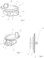
- the apparatus for radiation protection of the eyes comprises a housing 1, which consists of a shell-like frame 2, with an open back, which protects the wearer's head including the area around the eyes and the temples on the sides encloses light-tight. Furthermore, the shell-like frame 2 is attached to a carrying device 3 for placement on the head and is provided with a nose pad 4 for positioning and supporting the shell-like frame 3 on the bridge of the wearer's nose.
- a front opening 5 which extends essentially over its entire width, for receiving a shield 6 made of a material which is impermeable to X-rays or ionizing radiation.
- the shielding 6 can also be made of another suitable material instead of lead, provided that the desired shielding is ensured. So that a weight reduction can be achieved.
- the radiation-impermeable material it is essential that the radiation dose reaching the eye is reduced to values close to zero.
- the shielding 5 can also encompass the side temple area, so that an even better protection against radiation for the eyes is achieved, which is particularly advantageous when the wearer of the apparatus turns his head to the side has, so that the front shield 5 no longer points in the direction of the source for the X-ray radiation. Thanks to the additional lateral shielding, the X-rays cannot accidentally enter the eyes from the side.
- the shell-like mount 2 can also be made entirely of a material that is impermeable or hardly permeable to X-rays.
- the carrying device 3 for the housing 1 is a ring 7 which is adapted or self-adapting to the shape of the wearer's head and to which the housing 1 with the shell-like mount 2 is suspended.
- this is a non-illustrated locking mechanism, or the like. adjustable in scope.
- a preferably pivotably mounted head pad 8 which is supported on the back of the head and allows the apparatus to be carried safely.
- the head pad 8 can also be used at least partially as a counterweight for the housing 1 connected to the ring 7 .
- a battery compartment could be accommodated in the head cushion 8 for this purpose, so that a more even pressure load on the head through the ring 7 is achieved.
- one or more carrying straps attached to the ring 7 can also be provided, which rest against the wearer's head from above when the apparatus is put on.
- the nose pad 4 and the ring 7 can be provided with padding, at least in the contact area with the head, ie the contact points.
- At least one display device 9 for stereoscopic display of video information which is coupled to an optical recording device 10 or a camera, which is arranged on the side of the shield 6 facing away from the wearer's eyes ,
- the images and image sequences recorded by the recording device 10 being transmitted directly and without delay to the display device 9 .
- This arrangement allows a dynamic image to be generated in front of the eyes of the wearer of the apparatus, which corresponds (at least largely) to the real image of a scene in front of the eye, with three-dimensional vision being possible without any problems, with the X-rays reaching the apparatus affecting the eyes of the patient wearer cannot reach, so that safe working is possible.
- Display device 9 can consist of a screen positioned in front of each eye inside the shell-like frame 2, which can optionally also have a round outline.
- the display device 9 can also consist of a single screen located in front of both eyes of the wearer, which is coupled to a shutter that generates the images for both eyes one after the other, so that a stereo impression is created for the wearer of the apparatus.
- the display device 9 can also be a split screen be that creates a separate image for each eye for a stereo impression.
- the wearer is provided with a realistic stereoscopic image of what is happening in front of the apparatus, which enables the medical staff to work safely and without harming the eyes.
- optics 11 for focusing the displayed image on the eyes are arranged between the wearer's eyes and the screen or screens, which enables fatigue-free viewing of the screen becomes.
- the optical recording device 10 or the camera can be a stereoscopic camera which is positioned directly in front of the shield 6 .
- two individual cameras can also be provided which are arranged at a distance from one another and next to one another, the distance between which can be adjusted to the distance between the eyes.
- the stereoscopic impression of the wearer of the apparatus can thus be adapted to the individual circumstances.
- the electrical connection between the playback device 9 and the recording device 9 for Power supply and information transmission takes place by means of a suitable rewiring, which is laid around the shield 6.
- the shell-like mount 2 rests on the head in a substantially light-tight manner, enclosing the wearer's eyes.
- the housing 1 or at least the shell-like mount should have an anti-reflective or matt surface on the inside, which can also be achieved, for example, by a matt or matt black coating. This ensures that the apparatus according to the invention can be used by a diagnostician to a large extent without tiring.
- a crystal-clear protective pane 12 is arranged in front of the stereoscopic camera or the individual cameras, which closes off the shell-like mount 2 at the front and can be detachably connected to the shell-like mount 2 .
- the particular advantage of the apparatus according to the invention can be seen in the fact that the area around the eyes, at least in the direction of the source of the X-rays, is completely shielded with an opaque, radiation-impermeable material, with the scene in front of the apparatus being displayed in real time by the display device 10 for stereoscopic display of video information the back of the shield 6 is reproduced.
- all components of the housing 1, such as the shell-like mount 2, the optics 11 and the protective pane 12, except for the shielding and the video recording and playback devices with associated electronics, are made of a plastic material that is as light as possible.
- Additional information such as blood pressure or other values, as well as image information from other examinations, etc. can also be displayed via the display device 10 .
Applications Claiming Priority (2)
| Application Number | Priority Date | Filing Date | Title |
|---|---|---|---|
| DE102016123634 | 2016-12-07 | ||
| PCT/EP2017/081858 WO2018104465A2 (de) | 2016-12-07 | 2017-12-07 | Apparatur zum strahlungsschutz der augen |
Publications (2)
| Publication Number | Publication Date |
|---|---|
| EP3551144A2 EP3551144A2 (de) | 2019-10-16 |
| EP3551144B1 true EP3551144B1 (de) | 2023-08-02 |
Family
ID=61132369
Family Applications (1)
| Application Number | Title | Priority Date | Filing Date |
|---|---|---|---|
| EP17837861.8A Active EP3551144B1 (de) | 2016-12-07 | 2017-12-07 | Apparatur zum strahlungsschutz der augen |
Country Status (7)
| Country | Link |
|---|---|
| US (1) | US11583447B2 (ru) |
| EP (1) | EP3551144B1 (ru) |
| CN (1) | CN110022804A (ru) |
| DK (1) | DK3551144T3 (ru) |
| EA (1) | EA035657B1 (ru) |
| ES (1) | ES2961503T3 (ru) |
| WO (1) | WO2018104465A2 (ru) |
Families Citing this family (4)
| Publication number | Priority date | Publication date | Assignee | Title |
|---|---|---|---|---|
| CN110664430A (zh) * | 2019-10-11 | 2020-01-10 | 上海市肺科医院 | 眼睛甲状腺一体化防辐射服 |
| US20230049355A1 (en) * | 2019-12-31 | 2023-02-16 | ResMed Asia Pte. Ltd. | Positioning, stabilising, and interfacing structures and system incorporating same |
| CN111568462A (zh) * | 2020-05-12 | 2020-08-25 | 河南省中医院(河南中医药大学第二附属医院) | 一种放射科用检查护理头部防护组件 |
| WO2022039357A1 (ko) * | 2020-08-20 | 2022-02-24 | 주식회사 오토스윙 | 용접 정보 제공 장치 |
Family Cites Families (27)
| Publication number | Priority date | Publication date | Assignee | Title |
|---|---|---|---|---|
| US4603442A (en) * | 1984-12-28 | 1986-08-05 | Barfield Kenneth E | Single lens goggle |
| DE8910235U1 (ru) | 1989-08-26 | 1989-10-05 | Fa. Carl Zeiss, 7920 Heidenheim, De | |
| US5619754A (en) * | 1995-02-13 | 1997-04-15 | Fibre-Metal Products, Co. | Protective cap with reversible headband |
| EP0780783A1 (de) | 1995-12-23 | 1997-06-25 | Deutsche ITT Industries GmbH | Virtual-Reality-Wiedergabesystem mit einer optischen Lageerkennungseinrichtung |
| DE10327017A1 (de) | 2003-06-16 | 2005-01-20 | Jk-Holding Gmbh | Augenschutz gegen Strahlung |
| GB0322551D0 (en) * | 2003-09-26 | 2003-10-29 | Keeler Ltd | Head-mounted instruments |
| US8334899B1 (en) * | 2007-11-01 | 2012-12-18 | Jefferson Science Associates, Llc | Protective laser beam viewing device |
| US8588448B1 (en) * | 2008-09-09 | 2013-11-19 | Energy Telecom, Inc. | Communication eyewear assembly |
| US8023195B2 (en) * | 2008-10-23 | 2011-09-20 | Gentex Corporation | Split laser eye protection system |
| US8569655B2 (en) * | 2009-10-13 | 2013-10-29 | Lincoln Global, Inc. | Welding helmet with integral user interface |
| US20110214082A1 (en) | 2010-02-28 | 2011-09-01 | Osterhout Group, Inc. | Projection triggering through an external marker in an augmented reality eyepiece |
| WO2011106797A1 (en) * | 2010-02-28 | 2011-09-01 | Osterhout Group, Inc. | Projection triggering through an external marker in an augmented reality eyepiece |
| US8976086B2 (en) * | 2010-12-03 | 2015-03-10 | Esight Corp. | Apparatus and method for a bioptic real time video system |
| US9073138B2 (en) * | 2011-05-16 | 2015-07-07 | Lincoln Global, Inc. | Dual-spectrum digital imaging welding helmet |
| EP2750607B1 (en) * | 2011-09-16 | 2019-05-01 | Koninklijke Philips N.V. | Live 3d x-ray viewing |
| US9480539B2 (en) * | 2011-11-03 | 2016-11-01 | James Ortlieb | Viewing system and viewing method for assisting user in carrying out surgery by identifying a target image |
| JP5987387B2 (ja) * | 2012-03-22 | 2016-09-07 | ソニー株式会社 | ヘッドマウントディスプレイ及び手術システム |
| FR2992549B1 (fr) * | 2012-06-27 | 2015-07-31 | Commissariat Energie Atomique | Dispositif de protection contre les rayonnements optiques et les projections solides ou liquides |
| KR20160005680A (ko) * | 2013-03-15 | 2016-01-15 | 임미 인크. | 비동공 형성 광 경로를 갖는 헤드마운트 디스플레이 |
| US20140333773A1 (en) * | 2013-05-11 | 2014-11-13 | Randy James Davis | Portable audio/ video mask |
| US9332903B2 (en) * | 2013-09-19 | 2016-05-10 | Gn Otometrics A/S | Headgear for observation of eye movements |
| US9506869B2 (en) * | 2013-10-16 | 2016-11-29 | Tsi, Incorporated | Handheld laser induced breakdown spectroscopy device |
| CN106105183B (zh) * | 2014-03-14 | 2019-05-21 | 索尼互动娱乐股份有限公司 | 头戴式显示器 |
| WO2015148323A1 (en) * | 2014-03-22 | 2015-10-01 | Radtec Medical Devices, Inc. | Shield with display |
| US10197816B2 (en) * | 2015-05-26 | 2019-02-05 | Lumenis Ltd. | Laser safety glasses with an improved imaging system |
| EP3235478A1 (en) * | 2016-04-18 | 2017-10-25 | Universität Wien | Protective eyewear |
| US10610179B2 (en) * | 2017-06-05 | 2020-04-07 | Biosense Webster (Israel) Ltd. | Augmented reality goggles having X-ray protection |
-
2017
- 2017-12-07 EP EP17837861.8A patent/EP3551144B1/de active Active
- 2017-12-07 CN CN201780074745.4A patent/CN110022804A/zh active Pending
- 2017-12-07 ES ES17837861T patent/ES2961503T3/es active Active
- 2017-12-07 EA EA201991372A patent/EA035657B1/ru unknown
- 2017-12-07 WO PCT/EP2017/081858 patent/WO2018104465A2/de unknown
- 2017-12-07 DK DK17837861.8T patent/DK3551144T3/da active
- 2017-12-07 US US16/465,719 patent/US11583447B2/en active Active
Also Published As
| Publication number | Publication date |
|---|---|
| EA201991372A1 (ru) | 2019-11-29 |
| ES2961503T3 (es) | 2024-03-12 |
| EP3551144A2 (de) | 2019-10-16 |
| US20190290491A1 (en) | 2019-09-26 |
| DK3551144T3 (da) | 2023-11-06 |
| EA035657B1 (ru) | 2020-07-22 |
| US11583447B2 (en) | 2023-02-21 |
| CN110022804A (zh) | 2019-07-16 |
| WO2018104465A3 (de) | 2018-08-02 |
| WO2018104465A2 (de) | 2018-06-14 |
Similar Documents
| Publication | Publication Date | Title |
|---|---|---|
| EP3551144B1 (de) | Apparatur zum strahlungsschutz der augen | |
| DE112016004662T5 (de) | Wearable-Display mit einstellbarer Pupillendistanz | |
| WO2007140642A1 (de) | Gesichts- und blendschutzvorrichtung für personen in arbeitsbereichen mit gefährlicher, schädlicher oder störender strahlung, insbesondere für schweisser | |
| WO2001038919A1 (de) | Sehhilfe in form einer lupenbrille mit autofokussiereinrightung | |
| DE2843661A1 (de) | Tragbares sichtgeraet | |
| EP1430349B1 (de) | Informationssystem | |
| DE102015001874A1 (de) | Vorrichtung und Verfahren zur Abstandsbestimmung und/oder Zentrierung unter Verwendung von Hornhautreflexionen | |
| WO2012100771A2 (de) | Videozentriersystem und verfahren zur bestimmung von zentrierdaten für brillengläser | |
| DE102005014759A1 (de) | Anzeigevorrichtung und Anzeigeverfahren | |
| DE60133693T2 (de) | Stereoskopische Bildanzeigevorrichtung | |
| DE102011087265A1 (de) | Medizinische Bildgebungsvorrichtung | |
| DE3143385A1 (de) | Nachtsichtinstrument | |
| DE102014017534A1 (de) | Anzeigevorrichtung, die auf den Kopf eines Benutzers aufsetzbar ist | |
| DE202012000167U1 (de) | Mobiles Videozentriersystem zur Bestimmung von Zentrierdaten für Brillengläser | |
| DE3628458A1 (de) | Vorrichtung zum raeumlichen sehen dreidimensionaler fernsehbilder | |
| WO2018028759A1 (de) | Laserschutzbrille zur vollständigen, wellenlängenunabhängigen abschirmung von hochleistungslaserstrahlen | |
| DE102008053395A1 (de) | Verfahren und Einrichtung zur fotografischen Bilderfassung des Gesichtsfelds einer Person | |
| DE202007016525U1 (de) | Weste für audiovisuelles System | |
| US8334899B1 (en) | Protective laser beam viewing device | |
| DE1804431A1 (de) | Beobachtungs- oder Betrachtungsbrille und Navigationsvefahren fuer ein Flugzeug | |
| EP1488768B1 (de) | Augenschutz gegen Strahlung | |
| DE2820878A1 (de) | Kamera-visieroptik | |
| DE102014017835A1 (de) | Laserschutzbrille mit 3D-Video-Einblendung | |
| WO2004025353A1 (de) | Am kopf tragbare anzeigevorrichtung bei verbessertem gesichtsfeld | |
| DE102004040148A1 (de) | Lichtschutzbrille |
Legal Events
| Date | Code | Title | Description |
|---|---|---|---|
| STAA | Information on the status of an ep patent application or granted ep patent |
Free format text: STATUS: UNKNOWN |
|
| STAA | Information on the status of an ep patent application or granted ep patent |
Free format text: STATUS: THE INTERNATIONAL PUBLICATION HAS BEEN MADE |
|
| PUAI | Public reference made under article 153(3) epc to a published international application that has entered the european phase |
Free format text: ORIGINAL CODE: 0009012 |
|
| STAA | Information on the status of an ep patent application or granted ep patent |
Free format text: STATUS: REQUEST FOR EXAMINATION WAS MADE |
|
| 17P | Request for examination filed |
Effective date: 20190705 |
|
| AK | Designated contracting states |
Kind code of ref document: A2 Designated state(s): AL AT BE BG CH CY CZ DE DK EE ES FI FR GB GR HR HU IE IS IT LI LT LU LV MC MK MT NL NO PL PT RO RS SE SI SK SM TR |
|
| AX | Request for extension of the european patent |
Extension state: BA ME |
|
| DAV | Request for validation of the european patent (deleted) | ||
| DAX | Request for extension of the european patent (deleted) | ||
| STAA | Information on the status of an ep patent application or granted ep patent |
Free format text: STATUS: EXAMINATION IS IN PROGRESS |
|
| STAA | Information on the status of an ep patent application or granted ep patent |
Free format text: STATUS: EXAMINATION IS IN PROGRESS |
|
| 17Q | First examination report despatched |
Effective date: 20210625 |
|
| GRAP | Despatch of communication of intention to grant a patent |
Free format text: ORIGINAL CODE: EPIDOSNIGR1 |
|
| STAA | Information on the status of an ep patent application or granted ep patent |
Free format text: STATUS: GRANT OF PATENT IS INTENDED |
|
| INTG | Intention to grant announced |
Effective date: 20230213 |
|
| GRAS | Grant fee paid |
Free format text: ORIGINAL CODE: EPIDOSNIGR3 |
|
| GRAA | (expected) grant |
Free format text: ORIGINAL CODE: 0009210 |
|
| STAA | Information on the status of an ep patent application or granted ep patent |
Free format text: STATUS: THE PATENT HAS BEEN GRANTED |
|
| AK | Designated contracting states |
Kind code of ref document: B1 Designated state(s): AL AT BE BG CH CY CZ DE DK EE ES FI FR GB GR HR HU IE IS IT LI LT LU LV MC MK MT NL NO PL PT RO RS SE SI SK SM TR |
|
| REG | Reference to a national code |
Ref country code: GB Ref legal event code: FG4D Free format text: NOT ENGLISH |
|
| REG | Reference to a national code |
Ref country code: CH Ref legal event code: EP |
|
| REG | Reference to a national code |
Ref country code: DE Ref legal event code: R096 Ref document number: 502017015157 Country of ref document: DE |
|
| REG | Reference to a national code |
Ref country code: IE Ref legal event code: FG4D Free format text: LANGUAGE OF EP DOCUMENT: GERMAN |
|
| REG | Reference to a national code |
Ref country code: CH Ref legal event code: PK Free format text: BERICHTIGUNGEN |
|
| REG | Reference to a national code |
Ref country code: DE Ref legal event code: R081 Ref document number: 502017015157 Country of ref document: DE Owner name: VACUTEC MESSTECHNIK GMBH, DE Free format text: FORMER OWNER: WOERMANN, BERND, 01328 DRESDEN, DE |
|
| RAP2 | Party data changed (patent owner data changed or rights of a patent transferred) |
Owner name: VACUTEC MESSTECHNIK GMBH |
|
| RIN2 | Information on inventor provided after grant (corrected) |
Inventor name: WOERMANN, BERND |
|
| REG | Reference to a national code |
Ref country code: DK Ref legal event code: T3 Effective date: 20231101 |
|
| REG | Reference to a national code |
Ref country code: NL Ref legal event code: FP |
|
| REG | Reference to a national code |
Ref country code: SE Ref legal event code: TRGR |
|
| REG | Reference to a national code |
Ref country code: LT Ref legal event code: MG9D |
|
| PG25 | Lapsed in a contracting state [announced via postgrant information from national office to epo] |
Ref country code: GR Free format text: LAPSE BECAUSE OF FAILURE TO SUBMIT A TRANSLATION OF THE DESCRIPTION OR TO PAY THE FEE WITHIN THE PRESCRIBED TIME-LIMIT Effective date: 20231103 |
|
| PGFP | Annual fee paid to national office [announced via postgrant information from national office to epo] |
Ref country code: GB Payment date: 20231220 Year of fee payment: 7 |
|
| PG25 | Lapsed in a contracting state [announced via postgrant information from national office to epo] |
Ref country code: IS Free format text: LAPSE BECAUSE OF FAILURE TO SUBMIT A TRANSLATION OF THE DESCRIPTION OR TO PAY THE FEE WITHIN THE PRESCRIBED TIME-LIMIT Effective date: 20231202 |
|
| PG25 | Lapsed in a contracting state [announced via postgrant information from national office to epo] |
Ref country code: RS Free format text: LAPSE BECAUSE OF FAILURE TO SUBMIT A TRANSLATION OF THE DESCRIPTION OR TO PAY THE FEE WITHIN THE PRESCRIBED TIME-LIMIT Effective date: 20230802 Ref country code: PT Free format text: LAPSE BECAUSE OF FAILURE TO SUBMIT A TRANSLATION OF THE DESCRIPTION OR TO PAY THE FEE WITHIN THE PRESCRIBED TIME-LIMIT Effective date: 20231204 Ref country code: NO Free format text: LAPSE BECAUSE OF FAILURE TO SUBMIT A TRANSLATION OF THE DESCRIPTION OR TO PAY THE FEE WITHIN THE PRESCRIBED TIME-LIMIT Effective date: 20231102 Ref country code: LV Free format text: LAPSE BECAUSE OF FAILURE TO SUBMIT A TRANSLATION OF THE DESCRIPTION OR TO PAY THE FEE WITHIN THE PRESCRIBED TIME-LIMIT Effective date: 20230802 Ref country code: LT Free format text: LAPSE BECAUSE OF FAILURE TO SUBMIT A TRANSLATION OF THE DESCRIPTION OR TO PAY THE FEE WITHIN THE PRESCRIBED TIME-LIMIT Effective date: 20230802 Ref country code: IS Free format text: LAPSE BECAUSE OF FAILURE TO SUBMIT A TRANSLATION OF THE DESCRIPTION OR TO PAY THE FEE WITHIN THE PRESCRIBED TIME-LIMIT Effective date: 20231202 Ref country code: HR Free format text: LAPSE BECAUSE OF FAILURE TO SUBMIT A TRANSLATION OF THE DESCRIPTION OR TO PAY THE FEE WITHIN THE PRESCRIBED TIME-LIMIT Effective date: 20230802 Ref country code: GR Free format text: LAPSE BECAUSE OF FAILURE TO SUBMIT A TRANSLATION OF THE DESCRIPTION OR TO PAY THE FEE WITHIN THE PRESCRIBED TIME-LIMIT Effective date: 20231103 Ref country code: FI Free format text: LAPSE BECAUSE OF FAILURE TO SUBMIT A TRANSLATION OF THE DESCRIPTION OR TO PAY THE FEE WITHIN THE PRESCRIBED TIME-LIMIT Effective date: 20230802 |
|
| PGFP | Annual fee paid to national office [announced via postgrant information from national office to epo] |
Ref country code: SE Payment date: 20231219 Year of fee payment: 7 Ref country code: NL Payment date: 20231228 Year of fee payment: 7 Ref country code: IT Payment date: 20231227 Year of fee payment: 7 Ref country code: FR Payment date: 20231220 Year of fee payment: 7 Ref country code: DK Payment date: 20231219 Year of fee payment: 7 Ref country code: DE Payment date: 20231207 Year of fee payment: 7 Ref country code: AT Payment date: 20231214 Year of fee payment: 7 |
|
| REG | Reference to a national code |
Ref country code: GB Ref legal event code: 732E Free format text: REGISTERED BETWEEN 20240118 AND 20240124 |
|
| PG25 | Lapsed in a contracting state [announced via postgrant information from national office to epo] |
Ref country code: PL Free format text: LAPSE BECAUSE OF FAILURE TO SUBMIT A TRANSLATION OF THE DESCRIPTION OR TO PAY THE FEE WITHIN THE PRESCRIBED TIME-LIMIT Effective date: 20230802 |
|
| REG | Reference to a national code |
Ref country code: ES Ref legal event code: FG2A Ref document number: 2961503 Country of ref document: ES Kind code of ref document: T3 Effective date: 20240312 |
|
| PGFP | Annual fee paid to national office [announced via postgrant information from national office to epo] |
Ref country code: ES Payment date: 20240118 Year of fee payment: 7 |