EP3550571B1 - Negative ion-based beam injector - Google Patents
Negative ion-based beam injector Download PDFInfo
- Publication number
- EP3550571B1 EP3550571B1 EP19157605.7A EP19157605A EP3550571B1 EP 3550571 B1 EP3550571 B1 EP 3550571B1 EP 19157605 A EP19157605 A EP 19157605A EP 3550571 B1 EP3550571 B1 EP 3550571B1
- Authority
- EP
- European Patent Office
- Prior art keywords
- accelerator
- injector
- plasma
- ion
- ion source
- Prior art date
- Legal status (The legal status is an assumption and is not a legal conclusion. Google has not performed a legal analysis and makes no representation as to the accuracy of the status listed.)
- Active
Links
Images


Classifications
-
- G—PHYSICS
- G21—NUCLEAR PHYSICS; NUCLEAR ENGINEERING
- G21B—FUSION REACTORS
- G21B1/00—Thermonuclear fusion reactors
- G21B1/11—Details
- G21B1/15—Particle injectors for producing thermonuclear fusion reactions, e.g. pellet injectors
-
- G—PHYSICS
- G21—NUCLEAR PHYSICS; NUCLEAR ENGINEERING
- G21K—TECHNIQUES FOR HANDLING PARTICLES OR IONISING RADIATION NOT OTHERWISE PROVIDED FOR; IRRADIATION DEVICES; GAMMA RAY OR X-RAY MICROSCOPES
- G21K1/00—Arrangements for handling particles or ionising radiation, e.g. focusing or moderating
-
- H—ELECTRICITY
- H05—ELECTRIC TECHNIQUES NOT OTHERWISE PROVIDED FOR
- H05H—PLASMA TECHNIQUE; PRODUCTION OF ACCELERATED ELECTRICALLY-CHARGED PARTICLES OR OF NEUTRONS; PRODUCTION OR ACCELERATION OF NEUTRAL MOLECULAR OR ATOMIC BEAMS
- H05H3/00—Production or acceleration of neutral particle beams, e.g. molecular or atomic beams
- H05H3/02—Molecular or atomic-beam generation, e.g. resonant beam generation
-
- H—ELECTRICITY
- H05—ELECTRIC TECHNIQUES NOT OTHERWISE PROVIDED FOR
- H05H—PLASMA TECHNIQUE; PRODUCTION OF ACCELERATED ELECTRICALLY-CHARGED PARTICLES OR OF NEUTRONS; PRODUCTION OR ACCELERATION OF NEUTRAL MOLECULAR OR ATOMIC BEAMS
- H05H7/00—Details of devices of the types covered by groups H05H9/00, H05H11/00, H05H13/00
- H05H7/08—Arrangements for injecting particles into orbits
-
- H—ELECTRICITY
- H05—ELECTRIC TECHNIQUES NOT OTHERWISE PROVIDED FOR
- H05H—PLASMA TECHNIQUE; PRODUCTION OF ACCELERATED ELECTRICALLY-CHARGED PARTICLES OR OF NEUTRONS; PRODUCTION OR ACCELERATION OF NEUTRAL MOLECULAR OR ATOMIC BEAMS
- H05H7/00—Details of devices of the types covered by groups H05H9/00, H05H11/00, H05H13/00
- H05H7/22—Details of linear accelerators, e.g. drift tubes
-
- H—ELECTRICITY
- H01—ELECTRIC ELEMENTS
- H01J—ELECTRIC DISCHARGE TUBES OR DISCHARGE LAMPS
- H01J27/00—Ion beam tubes
- H01J27/02—Ion sources; Ion guns
- H01J27/08—Ion sources; Ion guns using arc discharge
-
- H—ELECTRICITY
- H05—ELECTRIC TECHNIQUES NOT OTHERWISE PROVIDED FOR
- H05H—PLASMA TECHNIQUE; PRODUCTION OF ACCELERATED ELECTRICALLY-CHARGED PARTICLES OR OF NEUTRONS; PRODUCTION OR ACCELERATION OF NEUTRAL MOLECULAR OR ATOMIC BEAMS
- H05H7/00—Details of devices of the types covered by groups H05H9/00, H05H11/00, H05H13/00
- H05H7/08—Arrangements for injecting particles into orbits
- H05H2007/081—Sources
- H05H2007/082—Ion sources, e.g. ECR, duoplasmatron, PIG, laser sources
-
- Y—GENERAL TAGGING OF NEW TECHNOLOGICAL DEVELOPMENTS; GENERAL TAGGING OF CROSS-SECTIONAL TECHNOLOGIES SPANNING OVER SEVERAL SECTIONS OF THE IPC; TECHNICAL SUBJECTS COVERED BY FORMER USPC CROSS-REFERENCE ART COLLECTIONS [XRACs] AND DIGESTS
- Y02—TECHNOLOGIES OR APPLICATIONS FOR MITIGATION OR ADAPTATION AGAINST CLIMATE CHANGE
- Y02E—REDUCTION OF GREENHOUSE GAS [GHG] EMISSIONS, RELATED TO ENERGY GENERATION, TRANSMISSION OR DISTRIBUTION
- Y02E30/00—Energy generation of nuclear origin
- Y02E30/10—Nuclear fusion reactors
Definitions
- the subject matter described herein relates generally to neutral beam injectors and, more particularly, to a neutral beam injector based on negative ions.
- Extracting H - ions from plasma to form a beam is likewise more complicated than with H + ions, since the negative ions will be accompanied by a much larger current of electrons unless suppression measures are employed. Since the cross section for collisional stripping of the electron from an H- ion to produce an atom is considerably greater than the cross section for an H + ion to acquire an electron from a hydrogen molecule, the fraction of ions converted to neutrals during acceleration can be significant unless the gas line density in the accelerator path is minimized by operating the ion source at a low pressure. Ions prematurely neutralized during acceleration form a low energy tail, and generally have greater divergence than those which experience the full acceleration potential.
- Neutralization of the accelerated negative ion beam can be done in a gas target with an efficiency of about 60%.
- the usage of plasma and photon targets allows for the further increase in the neutralization efficiency of negative ions.
- Overall energy efficiency of the injector can be increased by recuperation of the energy of the ion species remaining in the beam after passing a neutralizer.
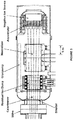
- FIG. 3 [2] The schematic diagram of a high-power neutral beam injector for the ITER tokomak, which is also typical for other reactor-grade magnetic plasma confinement systems under consideration, is shown in Fig. 3 [2].
- the basic components of the injector are a high-current source of negative ions, an ion accelerator, a neutralizer, and a magnetic separator of the charged component of the charge-exchanged beam with ion collectors-recuperators.
- a high vacuum pumping system typically is used with large size gate valves cutting the beam duct from the plasma device and/or providing access to major elements of the injector.
- the beam parameters are measured by using retractable calorimetric targets, as well as by non-invasive optical methods. Production of powerful neutral beams requires a corresponding power supply to be used.
- the sources of negative ions can be divided into the following groups:
- arc discharges with hot filaments or hollow cathodes are used, as well as RF discharges in hydrogen.
- discharges in a magnetic field are used.
- the systems with an external magnetic field i.e., with Penning or magnetron geometry of electrodes, with electron oscillation in the longitudinal magnetic field of the "reflective" discharge), and the systems with a peripheral magnetic field (multipole) are widely used.
- a cutaway view of the discharge chamber with a peripheral magnetic field developed for the neutral beam injector of JET is shown in Fig. 4 [3].
- a magnetic field at the periphery of the plasma box is produced by permanent magnets installed on its outer surface.
- the magnets are arranged in rows in which magnetization direction is constant or changes in staggered order, so that magnetic field lines have geometry of linear or checkerboard cusps near the wall.
- thermodynamic-equilibrium surface ionization where the slow atom or molecule impinging on the surface is emitted back as a positive or negative ion after a mean residence time
- non-equilibrium (kinetic) atom-surface interaction where negative ions are produced by sputtering, impact desorption (in contrast to thermal desorption where the thermal particles are desorbed) or reflection in the presence of an alkali metal coating.
- the adsorbed particles come off the surface in the conditions of thermal equilibrium.
- the ionization coefficient of the particles leaving the surface is determined by the Saha formula and appears to be very small ⁇ 0,02%.
- the level of the additional electron becomes higher than the upper energy level of the electrons in the metal, and resonance tunneling returns back the electron from the leaving ion back to the metal.
- the coefficient of negative ionization appears to be quite high for the surface with low work function which can be provided by covering an alkali metal, especially cesium.
- SPSs surface-plasma sources
- gas discharge plasma serves several functions, namely it produces intense fluxes of particles bombarding the electrodes; the plasma sheath adjacent to the electrode produces ion acceleration, thereby increasing the energy of the bombarding particles; negative ions, which are produced at electrodes under negative potential, are accelerated by the plasma sheath potential and come through the plasma layer into the extraction region without considerable destruction.
- An intense negative ion production with rather high power and gas efficiencies was obtained in various modifications of SPS under "dirty" gas-discharge conditions and an intense bombardment of the electrodes.
- Typical features of these sources can be understood considering the injector of a LHD stellarator [4], which is shown in Fig. 6 [4, 6].
- Arc plasma is produced in a large magnetic multipole bucket fence chamber with a volume of ⁇ 100 Liters. Twenty four tungsten filaments support the 3 kA, ⁇ 80 V arc under hydrogen pressure of about 0.3-0.4 Pa.
- An external magnet filter with a maximal field at center of ⁇ 50 G provides the electron density and temperature decrease in the extraction region near the plasma electrode.
- Positive bias of plasma electrode ( ⁇ 10 V) decreases an accompanying electron flux.
- Negative ions are produced on the plasma electrode covered by optimal cesium layer. External cesium ovens (three for one source) equipped with pneumatic valves supply the distributed cesium seeding. Negative ion production attains a maximum at optimal plasma electrode temperature of 200-250° C.
- the plasma electrode is thermally insulated and its temperature is determined by power loads plasma discharge.
- a four electrode multi-aperture ion-optical system which is used in the LHD ion source, is shown in Fig. 7 [6].
- Negative ions are extracted through 770 emission apertures with a diameter of 1.4 cm each. The apertures occupy an area of 25 x 125 cm 2 on the plasma electrode.
- Small permanent magnets are embedded into the extraction grid between apertures to deflect the co-extracted electrons from the beam onto the extraction electrode wall.
- An additional electron suppression grid, installed behind the extraction grid suppressed the secondary electrons, backscattered or emitted from the extracted electrode walls.
- a multi-slit grounded grid with high transparency is used in the ion source. It decreases the beam intersection area thus improving the voltage holding capacity and lowering the gas pressure in the gaps by a factor of 2.5 with the corresponding reduction of the beam stripping losses.
- Both the extraction electrode and the grounded electrode are water-cooled.
- Cesium seeding into the multi-cusp source provides a 5-fold increase of an extracted negative ion current and a linear growth of H - ions yield in the wide range of discharge powers and hydrogen filling pressures.
- Other important advantages of cesium seeding are a ⁇ 10-fold decrease of the co-extracted electron current and an essential decrease of hydrogen pressure in the discharge down to 0.3 Pa.
- the multi-cusp sources at LHD routinely provide about a 30 A ion current each with current density of 30 mA/cm 2 in 2 second long pulses [6].
- the main issues for the LHD ion sources is a blocking of cesium, which is seeded to the arc chamber, by the tungsten sputtered from filaments and the decrease of high voltage holding capacity when operated in the high-power long pulse regime.
- the negative-ion-based neutral beam injector of the LHD has two ion sources operated with hydrogen at nominal beam energy of 180keV. Every injector has achieved the nominal injection power of 5 MW during 128 sec pulse, so that each ion source provides a 2.5 MW neutral beam.
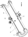
- Fig. 8 A and B shows the LHD neutral beam injector.
- a focal length of the ion source is 13m, and the pivot point of the two sources is located 15.4m downstream.
- Injection port is about 3m long with the narrowest part being 52cm in diameter and 68cm in length.
- the ion sources with RF plasma drivers and negative ion production on a plasma electrode covered by cesium are under development at IPP Garching.
- the RF drivers produce more clean plasma, so that there is no cesium blocking by tungsten in these sources.
- Steady state extraction of a negative ion beam pulse with a beam current of 1 A, energy of ⁇ 20 kV and duration of 3600 seconds was demonstrated by IPP in 2011.
- Linac4 Technical Design Report from CERN-AB-2006-084 by Arnaudon et al. discusses an H - linear accelerator intended to deliver a beam at 160 MeV energy. This Technical Design Report presents a detailed technical overview of the Linac4 design as it stood at the end of 2006.
- the present invention relates to a negative ion-based beam injector as defined by claim 1. Further, optional, details are provided in the dependent claims.
- the negative ion-based beam injector of claim 1 is comprised in a negative ion-based neutral beam injector, however, the invention relates only to the negative ion-based beam injector.
- Embodiments provided herein are directed to systems and methods for a negative ion-based neutral beam injector.
- the negative ion-based neutral beam injector comprises an ion source, an accelerator and a neutralizer to produce about a 5 MW neutral beam with energy of about 0.50 to 1.0 MeV.
- the ion source is located inside a vacuum tank and produces a 9 A negative ion beam.
- the ions produced by the ion source are pre-accelerated to 120 keV before injection into a high energy accelerator by an electrostatic multi aperture grid pre-accelerator in the ion source, which is used to extract ion beams from the plasma and accelerate to some fraction of the required beam energy.
- the 120 keV beam from the ion source passes through a pair of deflecting magnets, which enable the beam to shift off axis before entering the high energy accelerator. After acceleration to full energy, the beam enters the neutralizer where it is partially converted into a neutral beam. The remaining ion species are separated by a magnet and directed into electrostatic energy converters. The neutral beam passes through a gate valve and enters a plasma chamber.
- the plasma drivers and the internal walls of a plasma box of the ion source are maintained at elevated temperature (150-200° C) to prevent cesium accumulation on their surfaces.
- a distributing manifold is provided to supply cesium directly onto the surface of the plasma grids and not to the plasma. This is in contrast to existing ion sources which supply cesium directly into a plasma discharge chamber.
- a magnetic field used to deflect co-extracted electrons in ion extraction and pre-acceleration regions is produced by external magnets, not by magnets embedded into the grid body, as adopted in previous designs.
- the absence of embedded "low-temperature" magnets in the grids enables them to be heated up to elevated temperatures.
- Previous designs tend to utilize magnets embedded into the grid body, which tends to cause a significant reduction in extracted beam current and prevent elevated temperature operation as well as appropriate heating/cooling performance.
- the high voltage accelerator is not coupled directly to the ion source, but is spaced apart from the ion source by a transition zone (low energy beam transport line - LEBT) with bending magnets, vacuum pumps and cesium traps.
- the transition zone intercepts and removes most of the co-streaming particles including electrons, photons and neutrals from the beam, pumps out gas emanating from the ion source and prevents it from reaching the high-voltage accelerator, prevents cesium from flowing out of the ion source and penetrating to the high-voltage accelerator, prevents electrons and neutrals, produced by negative ions stripping, from entering the high-voltage accelerator.
- the ion source is directly connected to the high-voltage accelerator, which tends to cause the high-voltage accelerator to be subject to all gas, charged particle, and cesium flows from the ion source and vice versa.
- the bending magnets in the LEBT deflect and focus the beam onto the accelerator axis and, thus compensate any beam offset and deflection during transport through the magnetic field of the ion source.
- the offset between the axes of pre and high-voltage accelerators reduces the influx of co-streaming particles to the high-voltage accelerator and prevents the highly accelerated particles (positive ions and neutrals) from back-streaming into the pre-accelerator and ion source.
- the beam focusing also facilitates homogeneity of the beam entering the accelerator compared to the multi-aperture grid systems.
- the neutralizer includes a plasma neutralizer and a photon neutralizer.
- the plasma neutralizer is based on a multi-cusp plasma confinement system with high field permanent magnets at the walls.
- the photon neutralizer is a photon trap based on a cylindrical cavity with highly reflective walls and pumping with high efficiency lasers.
- Embodiments provided herein are directed to a new negative ion-based neutral beam injector with energy of preferably about 500-1000 keV and high overall energetic efficiency.
- the preferred arrangement of an embodiment of a negative ion-based neutral beam injector 100 is illustrated in Figs. 1 and 2 .
- the injector 100 includes an ion source 110, a gate valve 120, deflecting magnets 130 for deflecting a low energy beam line, an insulator-support 140, a high energy accelerator 150, a gate valve 160, a neutralizer tube (shown schematically) 170, a separating magnet (shown schematically) 180, a gate valve 190, pumping panels 200 and 202, a vacuum tank 210 (which is part of a vacuum vessel 250 discussed below), cryosorption pumps 220, and a triplet of quadrupole lenses 230.
- the injector 100 comprises an ion source 110, an accelerator 150 and a neutralizer 170 to produce about a 5 MW neutral beam with energy of about 0.50 to 1.0 MeV.
- the ion source 110 is located inside the vacuum tank 210 and produces a 9 A negative ion beam.
- the vacuum tank 210 is biased to -880 kV which is relative to ground and installed on insulating supports 140 inside a larger diameter tank 240 filled with SF 6 gas.
- the ions produced by the ion source are pre-accelerated to 120 keV before injection into the high energy accelerator 150 by an electrostatic multi aperture grid pre-accelerator 111 (see Fig. 9 ) in the ion source 110, which is used to extract ion beams from the plasma and accelerate to some fraction of the required beam energy.
- the 120 keV beam from the ion source 110 passes through a pair of deflecting magnets 130, which enable the beam to shift off axis before entering the high energy accelerator 150.
- the pumping panels 202 shown between the deflecting magnets 130 include a partition and cesium trap.
- the gas efficiency of the ion source 110 is assumed to be about 30%.
- a projected negative ion beam current of 9-10 A corresponds to 6-7 I ⁇ Torr/s gas puff in the ion source 110.
- the neutral gas flowing from the ion source 110 builds up to an average pressure in the pre-accelerator 111 of about 2 ⁇ 10 -4 Torr. At this pressure, the neutral gas causes ⁇ 10% striping loss of the ion beam inside the pre-accelerator 111.
- a low energy beam transport line region 205 with differential pumping from pumping panels 200 is used immediately after pre-acceleration to decrease the gas pressure down to ⁇ 10 -6 Torr before it reaches the high energy accelerator 150. This introduces an additional -5%' beam loss, but since it happens at a low pre-acceleration energy the power loss is relatively small.
- the charge exchange losses in the high energy accelerator 150 are below 1% at the 10 -6 Torr background pressure.
- the beam After acceleration to full energy of 1 MeV the beam enters a neutralizer 170 where it is partially converted into a neutral beam. The remaining ion species are separated by a magnet 180 and directed into electrostatic energy converters (not shown). The neutral beam passes through the gate valve 190 and enters a plasma chamber 270.
- the vacuum vessel 250 is broken down into two sections. One section contains the pre-accelerator 111 and low energy beam line 205 in the first vacuum tank 210. Another section houses a high energy beam line 265, the neutralizer 170 and charged particles energy converters/recuperators in a second vacuum tank 255. The sections of the vacuum vessel 250 are connected through a chamber 260 with the high energy accelerator tube 150 inside.
- the first vacuum tank 210 is the vacuum boundary of the pre-accelerator 111 and low energy beam line 205 and the larger diameter tank or outer vessel 240 is pressurized with SF 6 gas for high voltage insulation.
- the vacuum tanks 210 and 255 act as the support structure for the interior equipment, such as the magnets 130, cryosorption pumps 220, etc. Heat removal from the internal heat-bearing components will be accomplished with cooling tubes, which have to have insulation breaks in the case of the first vacuum tank 210, which is biased to -880kV.
- the ion source 110 includes: electrostatic multi-aperture pre-accelerator grids 111, ceramic insulators 112, RF- type plasma drivers 113, permanent magnets 114, a plasma box 115, water coolant channels and manifolds 116, and gas valves 117.
- a cesiated molybdenum surface of the plasma pre-accelerator grids 111 is used to convert the positive ions and neutral atoms formed by the plasma drivers 113 into negative ions in a plasma expansion volume (the volume between the drivers 113 and the grids 111, indicated by the bracket labeled "PE" in Fig. 9 ) with magnetic-multipole-bucket containment as provided by the permanent magnets 114.
- a positive bias voltage for collection of the electrons to the plasma pre-accelerator grids 111 is applied to optimized conditions for negative ion production.
- Geometric shaping of apertures 111B in plasma pre-accelerator grids 111 is used to focus H - ions into the apertures 111B of the extraction grid.
- a small transverse magnetic filter produced by external permanent magnets 114 is used to decrease the temperature of electrons diffused from the driver region or plasma emitter region PE of plasma box 115 to the extraction region ER of the plasma box 115. Electrons in the plasma are reflected back from the extraction region ER by the small transverse magnetic filter field produced by external permanent magnets 114.
- the ions are accelerated to 120 keV before injection into the high energy accelerator 150 by the electrostatic multi-aperture pre-accelerator plasma grids 111 in the ion source 110.
- the ion beam Before acceleration to high energy, the ion beam is about 35 cm in diameter.
- the ion source 110 therefore has to produce 26 mA/cm2 in the apertures 111B assuming 33% transparency in the pre-accelerator plasma grids 111.
- Plasma which feeds the plasma box 115, is produced by an array of plasma drivers 113 installed on a rear flange 115A of the plasma box, which is preferably a cylindrical water-cooled copper chamber (700 mm diameter by 170 mm long).
- the open end of the plasma box 115 is enclosed by the pre-accelerator plasma grids 111 of the extraction and acceleration system.
- Cesium is introduced into the plasma box 115 by use of a cesium supply system (not shown in Fig. 9 ).
- the ion source 110 is surrounded by permanent magnets 114 to form a line cusp configuration for primary electron and plasma confinements.
- the magnet columns 114A on the cylindrical wall of the plasma box 115 are connected at the rear flange 115A by rows of magnets 114B that are also in a line-cusp configuration.
- a magnetic filter near the plane of the plasma grids 111 divides the plasma box 115 into the plasma emitter PE and the extraction region ER.
- An electrode extraction and pre-acceleration system 111 comprises five electrodes 111C, 111D, 111E, 111F and 111G, each having 142 holes or apertures 111B formed orthogonal there through and used to provide a negative ion beam.
- the extraction apertures 111B are each 18 mm in diameter, so that total ion extraction area of the 142 extraction apertures is about 361 cm 2 .
- the negative ion current density is 25 mA/cm 2 and is required to produce a 9 A ion beam.
- the magnetic field of the filter magnets 114C is extended into the gaps between the electrostatic extractor and pre-accelerator grids 111 to deflect co-extracted electrons onto grooves at the inner surface of the apertures 111B in the extracting electrodes 111C, 111D, and 111E.
- the magnetic field of the magnetic filter magnets 114C together with the magnetic field of additional magnets 114D provides the deflection and interception of the electrons, co-extracted with negative ions.
- the additional magnets 114D include an array of magnets installed between the holders of the accelerator electrodes 111F and 111G of the accelerator grid located downstream from the extracting grid comprising extracting electrodes 111C, 111D, and 111E.
- the third grid electrode 111E which accelerates negative ions to an energy of 120 keV, is positively biased from the grounded grid electrode 111D to reflect back streaming positive ions entering the pre-accelerator grid.
- the plasma drivers 113 include two alternatives, namely an RF plasma driver and an arc-discharge atomic driver.
- a BINP-developed arc-discharge arc plasma generator is used in the atomic driver.
- a feature of the arc-discharge plasma generator consists of the formation of a directed plasma jet. Ions in the expanding jet move without collisions and due to acceleration by drop of ambipolar plasma potential gain energies of ⁇ 5-20 eV.
- the plasma jet can be directed on to an inclined molybdenum or tantalum surface of the converter (see 320 in Fig. 10 ), wherein as the result of neutralization and reflection of the jet a stream of hydrogen atoms is produced.
- the energy of hydrogen atoms can be increased beyond an initial 5-20 eV by negative biasing of the converter relative to the plasma box 115. Experiments on obtaining intensive streams of atoms with such a converter were performed in the Budker Institute in 1982-1984.
- a source of low energy atoms 300 is shown to include a gas valve 310, a cathode insert 312, an electrical feed through to a heater 314, cooling water manifolds 316, an LaB6 electron emitter 318, and an ion-atom converter 320.
- a stream of hydrogen atoms with an equivalent current of 20-25 A and energy varying in the range from 20 eV to 80 eV have been produced with an efficiency of more than 50%.
- Such a source can be used in the negative ion source to supply atoms with energy optimized for efficient generation of negative ions on the cesiated surface of plasma grids 111.
- the H- ions generated and pre-accelerated to an energy of 120keV by the ion source 110 on their passage along the low-energy beam transport line 205 are displaced perpendicular to their direction of motion by 440 mm with deviation by peripheral magnetic field of the ion source 110 and by a magnetic field of two special wedge-shaped bending magnets 130.
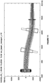
- This displacement of the negative ion beam in the low energy beam transport line 205 (as illustrated in Fig. 11 ) is provided to separate the ion source 110 and high-energy-accelerator regions 150.
- This displacement is used to avoid penetration of fast atoms originated from stripping of the H - beam on residual hydrogen in the accelerating tube 150, to reduce streams of cesium and hydrogen from the ion source 110 to the accelerating tube 150, and also for suppression of secondary ion flux from the accelerating tube 150 to the ion source 110.
- Fig. 11 the calculated trajectories of the H - ions in the low-energy beam transport line are shown.
- the low energy beam outgoing from the low energy beam line enters a conventional electrostatic multi aperture accelerator 150 shown in Fig. 12 .
- the calculation shows that the field strength does not exceed 50 kV/cm in the optimized accelerating tube 150 on electrodes in the zones of possible development of electron discharge.
- the beam goes through a triplet 230 of industry conventional quadrupole lenses 231, 232 and 233 ( Fig. 14 ), which are used to compensate slight beam defocusing on the exit of accelerating tube 150 and to form a beam with a preferred size on the exit port.
- the triplet 230 is installed inside the vacuum tank 255 of the high energy beam transport line 265.
- Each of the quadrupole lenses 231, 232 and 233 include a conventional set of quadrupole electromagnets that produce customary magnetic focusing fields as are found in all modern conventional particle accelerators.
- the calculated diameter of the neutral beam with a 6A equivalent current after the neutralizer at the distance of 12.5 m at half-height of the radial profile is 140 mm and 95 % of the beam current is in a 180mm diameter circumference.
- the photodetachment neutralizer 170 selected for the beam system can achieve more than 95% stripping of the ion beam.
- the neutralizer 170 comprises an array of xenon lamps and a cylindrical light trap with highly reflective walls to provide the required photon density. Cooled mirrors with a reflectivity greater than 0.99 are used to accommodate a power flux on the walls of about 70 kW/cm 2 .
- a plasma neutralizer using conventional technology could be used instead but with the expense of a slight decrease in efficiency. Nevertheless, -85% neutralization efficiency of a plasma cell is quite sufficient if an energy recovery system has >95% efficiency, as predicted.
- the plasma neutralizer plasma is confined in a cylindrical chamber 175 with multi-pole magnetic field at the walls, which is produced by an array of permanent magnets 172.
- General view of the confinement device is shown in Fig. 16 .
- the neutralizer 170 includes cooling water manifolds 171, permanent magnets 172, cathode assembles 173, and LaB6 cathodes 174.
- the cylindrical chamber 175 is 1.5-2m long and has openings at the ends for beam passing through.
- Plasma is generated by using several cathode assembles 173 installed at the center of the confinement chamber 175.
- Working gas is supplied near the center of the device 170.
- the direct converter converts a substantial portion of the energy contained in the residual rejected ion beam directly to electricity and supplies the rest of the energy as high quality heat for incorporation in the thermal cycle.
- the direct converters follow the design of an electrostatic multi aperture decelerator, whereby consecutive sections of charged electrodes produce the longitudinal breaking fields and absorb the kinetic energy of the ions.
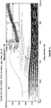
- Fig. 17 shows the results of two-dimensional calculations of ion beam deceleration in the converter. From the presented calculations, it follows that the deceleration of the ion beam with 1MeV energy down to 30 keV energy is quite feasible, thus, the value of recuperation factor of 96-97 % can be obtained.
- a high temperature fluid is circulated through all components.
- the temperature of the surfaces is further stabilized via active feed back control, i.e.: heat is either removed or added during CW operation and transient regimes.
- active feed back control i.e.: heat is either removed or added during CW operation and transient regimes.
- all other existing and planned beam injectors use passive systems with water cooling and thermal breaks between the coolant tubes and the hot electrode bodies.
- Cesium is supplied through a distributing manifold directly onto surface of the plasma grids 111, not to the plasma. Supplying cesium through a distributing manifold:
- a magnetic field used to deflect co-extracted electrons in the ion extraction and pre-acceleration regions is produced by external magnets, not by magnets embedded into the grid body, as adopted in previous designs:
- Electrodes 111 All of the electrodes of ion-optical system (grids 111) are always sustained at elevated temperature (150-200° C) to prevent cesium accumulation at their surfaces and to increase the high-voltage strength of extracting and pre-accelerating gaps. In contrast, in conventional designs, the electrodes are cooled by water. The electrodes have elevated temperatures because there are thermal breaks between the coolant tubes and the electrode bodies, and there is no active feed back.
- Initial warming up of the grids 111 at start up and heat removal during the beam-on phase is performed by running a hot liquid with a controllable temperature through the internal channels inside the grids 111.
- Gas is additionally pumped out from the pre-accelerating gap through the side space and large openings in the grid holders in order to decrease gas pressure along beam line and to suppress negative ions stripping and production/multiplying of secondary particles in the gaps.
- the high voltage accelerator 150 is not coupled directly to the ion source, but is spaced apart from the ion source by a transition zone (low energy beam transport line - LEBT 205) with bending magnets 130, vacuum pumps and cesium traps.
- the transition zone low energy beam transport line - LEBT 205
- the ion source is directly connected to the high-voltage accelerator. This causes the high-voltage accelerator to be subject to all gas, charged particle, and cesium flows from the ion source and vice versa. This strong interference reduces the voltage holding capacity of the high-voltage accelerator.
- Bending magnets 130 in the LEBT 205 deflect and focus the beam onto the accelerator axis.
- the magnets of the low energy beam line 205 focus the beam into the entrance of the single aperture accelerator 150:
- Magnetic lenses 230 are used after acceleration to compensate for over focusing in the accelerator 150 and to form a quasi-parallel beam.
- Plasma neutralizer based on a multi-cusp plasma confinement system with high field permanent magnets at the walls;
- Photon neutralizer - photon trap based on a cylindrical cavity with highly reflective walls and pumping with high efficiency lasers.
- recuperation is not foreseen in conventional designs at all.
Landscapes
- Physics & Mathematics (AREA)
- Engineering & Computer Science (AREA)
- Spectroscopy & Molecular Physics (AREA)
- Plasma & Fusion (AREA)
- General Engineering & Computer Science (AREA)
- Chemical & Material Sciences (AREA)
- High Energy & Nuclear Physics (AREA)
- Chemical Kinetics & Catalysis (AREA)
- Combustion & Propulsion (AREA)
- Particle Accelerators (AREA)
- Plasma Technology (AREA)
- Electron Sources, Ion Sources (AREA)
- Saccharide Compounds (AREA)
- Physical Vapour Deposition (AREA)
- Apparatus For Disinfection Or Sterilisation (AREA)
Priority Applications (5)
| Application Number | Priority Date | Filing Date | Title |
|---|---|---|---|
| SI201331969T SI3550571T1 (sl) | 2012-09-04 | 2013-09-04 | Injektor snopa na osnovi negativnih ionov |
| SM20220140T SMT202200140T1 (it) | 2012-09-04 | 2013-09-04 | Iniettore di fascio a base di ioni negativi. |
| HRP20220357TT HRP20220357T8 (hr) | 2012-09-04 | 2013-09-04 | Injektor snopa zasnovan na negativnim ionima |
| RS20220258A RS63056B1 (sr) | 2012-09-04 | 2013-09-04 | Injektor snopa zasnovan na negativnim jonima |
| PL19157605T PL3550571T3 (pl) | 2012-09-04 | 2013-09-04 | Wtryskiwacz z wiązką opartą na jonach ujemnych |
Applications Claiming Priority (4)
| Application Number | Priority Date | Filing Date | Title |
|---|---|---|---|
| RU2012137795A RU2619923C2 (ru) | 2012-09-04 | 2012-09-04 | Инжектор пучка нейтральных частиц на основе отрицательных ионов |
| US201361775444P | 2013-03-08 | 2013-03-08 | |
| PCT/US2013/058093 WO2014039579A2 (en) | 2012-09-04 | 2013-09-04 | Negative ion-based neutral beam injector |
| EP13765855.5A EP2893536B1 (en) | 2012-09-04 | 2013-09-04 | Negative ion-based neutral beam injector |
Related Parent Applications (1)
| Application Number | Title | Priority Date | Filing Date |
|---|---|---|---|
| EP13765855.5A Division EP2893536B1 (en) | 2012-09-04 | 2013-09-04 | Negative ion-based neutral beam injector |
Publications (2)
| Publication Number | Publication Date |
|---|---|
| EP3550571A1 EP3550571A1 (en) | 2019-10-09 |
| EP3550571B1 true EP3550571B1 (en) | 2021-12-22 |
Family
ID=50191556
Family Applications (2)
| Application Number | Title | Priority Date | Filing Date |
|---|---|---|---|
| EP19157605.7A Active EP3550571B1 (en) | 2012-09-04 | 2013-09-04 | Negative ion-based beam injector |
| EP13765855.5A Active EP2893536B1 (en) | 2012-09-04 | 2013-09-04 | Negative ion-based neutral beam injector |
Family Applications After (1)
| Application Number | Title | Priority Date | Filing Date |
|---|---|---|---|
| EP13765855.5A Active EP2893536B1 (en) | 2012-09-04 | 2013-09-04 | Negative ion-based neutral beam injector |
Country Status (31)
Families Citing this family (27)
| Publication number | Priority date | Publication date | Assignee | Title |
|---|---|---|---|---|
| US9591740B2 (en) | 2013-03-08 | 2017-03-07 | Tri Alpha Energy, Inc. | Negative ion-based neutral beam injector |
| JP6266399B2 (ja) * | 2014-03-26 | 2018-01-24 | 住友重機械工業株式会社 | 中性子捕捉療法装置 |
| RU2696268C2 (ru) | 2014-11-19 | 2019-08-01 | Таэ Текнолоджиз, Инк. | Фотонный нейтрализатор для инжекторов пучков нейтральных частиц |
| CN106935278B (zh) * | 2015-12-30 | 2019-03-26 | 核工业西南物理研究院 | 一种中性束注入器支撑与对接装置 |
| CN106932809B (zh) * | 2015-12-30 | 2023-07-14 | 核工业西南物理研究院 | 一种w字形多板变角组合结构的主动水冷量热靶结构 |
| CN106932808B (zh) * | 2015-12-30 | 2023-07-14 | 核工业西南物理研究院 | 一种长脉冲主动水冷量热靶大流量的异形水路结构 |
| CN106507576A (zh) * | 2016-11-04 | 2017-03-15 | 中国工程物理研究院流体物理研究所 | 金属氢化物离子源的离子过滤装置、方法及中子发生器 |
| US9865433B1 (en) * | 2016-12-19 | 2018-01-09 | Varian Semiconductor Equipment Associats, Inc. | Gas injection system for ion beam device |
| CN106783491A (zh) * | 2016-12-23 | 2017-05-31 | 信利(惠州)智能显示有限公司 | 一种离子注入设备及其使用方法 |
| CN107318213B (zh) * | 2017-07-06 | 2019-05-31 | 复旦大学 | 高电荷态离子的实验装置 |
| CN107833817B (zh) * | 2017-10-18 | 2019-05-21 | 东莞中子科学中心 | 一种铯催化负氢离子潘宁源的除铯方法及除铯引出电源 |
| CN107946159B (zh) * | 2017-11-24 | 2019-07-23 | 新奥科技发展有限公司 | 一种可调式离子源及静电约束聚变反应器 |
| RU2683963C1 (ru) * | 2018-04-04 | 2019-04-03 | федеральное государственное автономное образовательное учреждение высшего образования "Национальный исследовательский ядерный университет "МИФИ" (НИЯУ МИФИ) | Импульсный генератор термоядерных нейтронов |
| US11251075B2 (en) * | 2018-08-06 | 2022-02-15 | Mattson Technology, Inc. | Systems and methods for workpiece processing using neutral atom beams |
| US11482342B2 (en) * | 2018-10-07 | 2022-10-25 | Tanner L. Horne | Nuclear fusion reactor with toroidal superconducting magnetic coils implementing inertial electrostatic heating |
| CN112151196B (zh) * | 2019-06-28 | 2024-08-09 | 核工业西南物理研究院 | 一种具有三棱柱反射阵列的气体靶中性化器 |
| US11678430B2 (en) | 2019-08-30 | 2023-06-13 | Tae Technologies, Inc. | Neutron generating target for neutron beam systems |
| JP2022546687A (ja) * | 2019-08-30 | 2022-11-07 | ティーエーイー テクノロジーズ, インコーポレイテッド | 高品質イオンビーム形成のためのシステム、デバイス、および方法 |
| CN112927820B (zh) * | 2019-12-05 | 2024-07-16 | 核工业西南物理研究院 | 一种nnbi正负离子束偏及离子吞噬一体化结构 |
| RU2735945C1 (ru) * | 2020-03-03 | 2020-11-11 | Игорь Васильевич ВИНЯР | Центробежный инжектор макрочастиц термоядерного топлива |
| US12127325B2 (en) | 2020-04-09 | 2024-10-22 | Tae Technologies, Inc. | Systems, devices, and methods for secondary particle suppression from a charge exchange device |
| CN111741585B (zh) * | 2020-05-26 | 2021-09-03 | 中国原子能科学研究院 | 一种用于标记中子束无损检测的移动式d-t中子发生器 |
| CN111755317B (zh) * | 2020-06-30 | 2023-03-14 | 中国科学院近代物理研究所 | 一种用于二次离子质谱仪的射频负离子源 |
| US12035457B2 (en) | 2020-07-23 | 2024-07-09 | Tae Technologies, Inc. | Systems, devices, and methods for deformation reduction and resistance in metallic bodies |
| CN118679528A (zh) | 2022-03-14 | 2024-09-20 | 普林斯顿大学受托公司 | 平面线圈仿星器 |
| CN118679529A (zh) | 2022-03-14 | 2024-09-20 | 普林斯顿大学受托公司 | 用于仿星器中子源的系统和方法 |
| GB2619948B (en) * | 2022-06-22 | 2024-06-12 | Fusion Reactors Ltd | Neutral beam injection apparatus and method |
Family Cites Families (30)
| Publication number | Priority date | Publication date | Assignee | Title |
|---|---|---|---|---|
| US4093858A (en) * | 1977-06-06 | 1978-06-06 | The United States Of America As Represented By The United States Department Of Energy | Cesium injection system for negative ion duoplasmatrons |
| US4127442A (en) * | 1977-06-16 | 1978-11-28 | The United States Of America As Represented By The United States Department Of Energy | Charge exchange cooling in the tandem mirror plasma confinement apparatus |
| SU818366A1 (ru) * | 1979-09-17 | 1987-08-23 | Московский авиационный институт им.Серго Орджоникидзе | Источник ионов |
| JPS57191940A (en) * | 1981-05-22 | 1982-11-25 | Univ Kyoto | Negative hydrogen or heavy hydrogen ion source using semiconductor |
| US4439395A (en) * | 1981-04-13 | 1984-03-27 | The United States Of America As Represented By The United States Department Of Energy | Neutral beamline with improved ion energy recovery |
| US4588955A (en) * | 1983-06-01 | 1986-05-13 | The United States Of America As Represented By The United States Department Of Energy | Transverse field focused system |
| JPH01213998A (ja) * | 1988-02-22 | 1989-08-28 | Japan Atom Energy Res Inst | 負イオン源を用いた中性粒子入射装置 |
| JPH02183998A (ja) * | 1989-01-11 | 1990-07-18 | Hitachi Ltd | 中性粒子入射装置 |
| US4960990A (en) * | 1989-12-26 | 1990-10-02 | The United States Of America As Represented By The Secretary Of The Army | Non coherent photoneutralizer |
| RU2038708C1 (ru) * | 1992-01-16 | 1995-06-27 | Институт теоретической и экспериментальной физики | Ускоряющая структура для линейного резонансного ускорителя ионов с сеточной фокусировкой |
| US5365070A (en) * | 1992-04-29 | 1994-11-15 | The Regents Of The University Of California | Negative ion beam injection apparatus with magnetic shield and electron removal means |
| US5581156A (en) * | 1995-07-31 | 1996-12-03 | The United States Of America As Represented By The Secretary Of The Army | HF sustained, DC discharge driven negative ion source with automatic control system |
| JPH0980200A (ja) * | 1995-09-08 | 1997-03-28 | Nissin Electric Co Ltd | イオン発生装置 |
| DE19653927C1 (de) * | 1996-10-21 | 1998-04-23 | Koenig & Bauer Albert Ag | Bogenbearbeitungsmaschine |
| JP3789655B2 (ja) * | 1998-09-03 | 2006-06-28 | 独立行政法人 日本原子力研究開発機構 | セシウム導入装置 |
| JP2002022870A (ja) * | 2000-07-13 | 2002-01-23 | Toshiba Corp | 中性粒子入射装置 |
| US6534775B1 (en) * | 2000-09-01 | 2003-03-18 | Axcelis Technologies, Inc. | Electrostatic trap for particles entrained in an ion beam |
| JP2003270400A (ja) * | 2002-03-18 | 2003-09-25 | Taiyo Material:Kk | 中性子発生管用pig型負イオン源 |
| JP4113772B2 (ja) * | 2002-12-26 | 2008-07-09 | 株式会社東芝 | 負イオン源および負イオンビーム発生方法 |
| US6879109B2 (en) * | 2003-05-15 | 2005-04-12 | Axcelis Technologies, Inc. | Thin magnetron structures for plasma generation in ion implantation systems |
| JP2005116312A (ja) * | 2003-10-07 | 2005-04-28 | Toshiba Corp | マイクロ波プラズマ発生装置 |
| WO2006096772A2 (en) * | 2005-03-07 | 2006-09-14 | The Regents Of The University Of California | Plasma electric generation system |
| CA2609908A1 (en) * | 2005-05-27 | 2006-12-07 | Ionwerks, Inc. | Multi-beam ion mobility time-of-flight mass spectrometry with multi-channel data recording |
| RU2429591C2 (ru) * | 2008-02-28 | 2011-09-20 | Федеральное государственное унитарное предприятие "Центральный научно-исследовательский институт машиностроения" (ФГУП ЦНИИмаш) | Способ нейтрализации объемного заряда ионных пучков в ионных электрических ракетных двигателях и устройство для его осуществления (варианты) |
| US8309941B2 (en) * | 2008-05-22 | 2012-11-13 | Vladimir Balakin | Charged particle cancer therapy and patient breath monitoring method and apparatus |
| US8487278B2 (en) * | 2008-05-22 | 2013-07-16 | Vladimir Yegorovich Balakin | X-ray method and apparatus used in conjunction with a charged particle cancer therapy system |
| EP2283707B1 (en) * | 2008-05-22 | 2018-06-27 | Vladimir Yegorovich Balakin | Charged particle beam injection apparatus used in conjunction with a charged particle cancer therapy system |
| US8237135B2 (en) * | 2009-01-22 | 2012-08-07 | Axcelis Technologies, Inc. | Enhanced low energy ion beam transport in ion implantation |
| US8309936B2 (en) * | 2009-02-27 | 2012-11-13 | Trustees Of Columbia University In The City Of New York | Ion deflector for two-dimensional control of ion beam cross sectional spread |
| JP2012519532A (ja) * | 2009-03-04 | 2012-08-30 | ザクリトエ アクツィアニェールナエ オーブシチェストヴォ プロトム | 多方向荷電粒子線癌治療方法及び装置 |
-
2012
- 2012-09-04 RU RU2012137795A patent/RU2619923C2/ru active
-
2013
- 2013-04-09 UA UAA201503114A patent/UA118959C2/uk unknown
- 2013-09-04 KR KR1020207022598A patent/KR102208372B1/ko active Active
- 2013-09-04 PL PL19157605T patent/PL3550571T3/pl unknown
- 2013-09-04 SG SG10201705839PA patent/SG10201705839PA/en unknown
- 2013-09-04 HR HRP20190684TT patent/HRP20190684T1/hr unknown
- 2013-09-04 CN CN201710416714.4A patent/CN107316662B/zh active Active
- 2013-09-04 JP JP2015530153A patent/JP6216380B2/ja active Active
- 2013-09-04 NZ NZ733021A patent/NZ733021A/en not_active IP Right Cessation
- 2013-09-04 EA EA201590506A patent/EA030239B1/ru unknown
- 2013-09-04 CA CA2883669A patent/CA2883669C/en active Active
- 2013-09-04 NZ NZ705667A patent/NZ705667A/en not_active IP Right Cessation
- 2013-09-04 AU AU2013312795A patent/AU2013312795B2/en not_active Ceased
- 2013-09-04 MX MX2015002783A patent/MX345053B/es active IP Right Grant
- 2013-09-04 LT LTEP19157605.7T patent/LT3550571T/lt unknown
- 2013-09-04 EP EP19157605.7A patent/EP3550571B1/en active Active
- 2013-09-04 KR KR1020157008630A patent/KR102144601B1/ko active Active
- 2013-09-04 RS RS20190414A patent/RS58649B1/sr unknown
- 2013-09-04 SM SM20220140T patent/SMT202200140T1/it unknown
- 2013-09-04 EA EA201890602A patent/EA039453B1/ru unknown
- 2013-09-04 DK DK13765855.5T patent/DK2893536T3/en active
- 2013-09-04 NZ NZ745718A patent/NZ745718A/en not_active IP Right Cessation
- 2013-09-04 SM SM20190237T patent/SMT201900237T1/it unknown
- 2013-09-04 MY MYPI2015700550A patent/MY171879A/en unknown
- 2013-09-04 RS RS20220258A patent/RS63056B1/sr unknown
- 2013-09-04 EP EP13765855.5A patent/EP2893536B1/en active Active
- 2013-09-04 PE PE2015000285A patent/PE20151215A1/es active IP Right Grant
- 2013-09-04 HR HRP20220357TT patent/HRP20220357T8/hr unknown
- 2013-09-04 WO PCT/US2013/058093 patent/WO2014039579A2/en not_active Application Discontinuation
- 2013-09-04 PL PL13765855T patent/PL2893536T3/pl unknown
- 2013-09-04 MY MYPI2019006320A patent/MY199987A/en unknown
- 2013-09-04 CN CN201380057640.XA patent/CN104903967B/zh active Active
- 2013-09-04 SG SG11201501587WA patent/SG11201501587WA/en unknown
- 2013-09-04 HU HUE19157605A patent/HUE058277T2/hu unknown
- 2013-09-04 SI SI201331426T patent/SI2893536T1/sl unknown
- 2013-09-04 PT PT191576057T patent/PT3550571T/pt unknown
- 2013-09-04 MX MX2017000638A patent/MX378094B/es unknown
- 2013-09-04 SI SI201331969T patent/SI3550571T1/sl unknown
- 2013-09-04 DK DK19157605.7T patent/DK3550571T3/da active
- 2013-09-04 BR BR112015004801-3A patent/BR112015004801B1/pt not_active IP Right Cessation
- 2013-09-04 ES ES19157605T patent/ES2907075T3/es active Active
- 2013-09-04 ES ES13765855T patent/ES2723201T3/es active Active
- 2013-09-04 BR BR122020018713-1A patent/BR122020018713B1/pt active IP Right Grant
- 2013-09-04 PT PT13765855T patent/PT2893536T/pt unknown
- 2013-09-04 LT LTEP13765855.5T patent/LT2893536T/lt unknown
- 2013-09-04 HU HUE13765855A patent/HUE043299T2/hu unknown
-
2015
- 2015-02-24 PH PH12015500403A patent/PH12015500403B1/en unknown
- 2015-02-27 CL CL2015000480A patent/CL2015000480A1/es unknown
- 2015-03-04 IL IL237570A patent/IL237570A/en active IP Right Grant
- 2015-03-31 ZA ZA2015/02214A patent/ZA201502214B/en unknown
-
2017
- 2017-08-18 AU AU2017216558A patent/AU2017216558B2/en not_active Ceased
- 2017-08-20 IL IL254061A patent/IL254061B/en unknown
- 2017-09-22 JP JP2017182033A patent/JP6549666B2/ja not_active Expired - Fee Related
-
2018
- 2018-04-26 PH PH12018500893A patent/PH12018500893A1/en unknown
-
2022
- 2022-03-15 CY CY20221100205T patent/CY1125123T1/el unknown
Also Published As
Similar Documents
| Publication | Publication Date | Title |
|---|---|---|
| US11363708B2 (en) | Negative ion-based beam injector | |
| EP3550571B1 (en) | Negative ion-based beam injector | |
| US8468794B1 (en) | Electric propulsion apparatus | |
| Ivanov et al. | Development of a negative ion-based neutral beam injector in Novosibirsk | |
| RU2741793C2 (ru) | Инжектор пучка нейтральных частиц на основе отрицательных ионов | |
| HK1246498B (zh) | 基於负离子的中性束注入器 | |
| HK1246498A1 (zh) | 基於負離子的中性束注入器 | |
| HK1214675B (en) | Negative ion-based neutral beam injector |
Legal Events
| Date | Code | Title | Description |
|---|---|---|---|
| REG | Reference to a national code |
Ref country code: HR Ref legal event code: TUEP Ref document number: P20220357T Country of ref document: HR |
|
| PUAI | Public reference made under article 153(3) epc to a published international application that has entered the european phase |
Free format text: ORIGINAL CODE: 0009012 |
|
| STAA | Information on the status of an ep patent application or granted ep patent |
Free format text: STATUS: THE APPLICATION HAS BEEN PUBLISHED |
|
| AC | Divisional application: reference to earlier application |
Ref document number: 2893536 Country of ref document: EP Kind code of ref document: P |
|
| AK | Designated contracting states |
Kind code of ref document: A1 Designated state(s): AL AT BE BG CH CY CZ DE DK EE ES FI FR GB GR HR HU IE IS IT LI LT LU LV MC MK MT NL NO PL PT RO RS SE SI SK SM TR |
|
| STAA | Information on the status of an ep patent application or granted ep patent |
Free format text: STATUS: REQUEST FOR EXAMINATION WAS MADE |
|
| 17P | Request for examination filed |
Effective date: 20200406 |
|
| RBV | Designated contracting states (corrected) |
Designated state(s): AL AT BE BG CH CY CZ DE DK EE ES FI FR GB GR HR HU IE IS IT LI LT LU LV MC MK MT NL NO PL PT RO RS SE SI SK SM TR |
|
| GRAP | Despatch of communication of intention to grant a patent |
Free format text: ORIGINAL CODE: EPIDOSNIGR1 |
|
| STAA | Information on the status of an ep patent application or granted ep patent |
Free format text: STATUS: GRANT OF PATENT IS INTENDED |
|
| INTG | Intention to grant announced |
Effective date: 20210705 |
|
| GRAS | Grant fee paid |
Free format text: ORIGINAL CODE: EPIDOSNIGR3 |
|
| GRAA | (expected) grant |
Free format text: ORIGINAL CODE: 0009210 |
|
| STAA | Information on the status of an ep patent application or granted ep patent |
Free format text: STATUS: THE PATENT HAS BEEN GRANTED |
|
| AC | Divisional application: reference to earlier application |
Ref document number: 2893536 Country of ref document: EP Kind code of ref document: P |
|
| AK | Designated contracting states |
Kind code of ref document: B1 Designated state(s): AL AT BE BG CH CY CZ DE DK EE ES FI FR GB GR HR HU IE IS IT LI LT LU LV MC MK MT NL NO PL PT RO RS SE SI SK SM TR |
|
| REG | Reference to a national code |
Ref country code: GB Ref legal event code: FG4D |
|
| REG | Reference to a national code |
Ref country code: CH Ref legal event code: EP |
|
| REG | Reference to a national code |
Ref country code: DE Ref legal event code: R096 Ref document number: 602013080520 Country of ref document: DE |
|
| REG | Reference to a national code |
Ref country code: AT Ref legal event code: REF Ref document number: 1457606 Country of ref document: AT Kind code of ref document: T Effective date: 20220115 |
|
| REG | Reference to a national code |
Ref country code: IE Ref legal event code: FG4D |
|
| REG | Reference to a national code |
Ref country code: PT Ref legal event code: SC4A Ref document number: 3550571 Country of ref document: PT Date of ref document: 20220204 Kind code of ref document: T Free format text: AVAILABILITY OF NATIONAL TRANSLATION Effective date: 20220128 |
|
| REG | Reference to a national code |
Ref country code: RO Ref legal event code: EPE |
|
| REG | Reference to a national code |
Ref country code: FI Ref legal event code: FGE |
|
| REG | Reference to a national code |
Ref country code: NL Ref legal event code: FP |
|
| REG | Reference to a national code |
Ref country code: DK Ref legal event code: T3 Effective date: 20220308 |
|
| REG | Reference to a national code |
Ref country code: SE Ref legal event code: TRGR |
|
| REG | Reference to a national code |
Ref country code: EE Ref legal event code: FG4A Ref document number: E022068 Country of ref document: EE Effective date: 20220301 |
|
| REG | Reference to a national code |
Ref country code: ES Ref legal event code: FG2A Ref document number: 2907075 Country of ref document: ES Kind code of ref document: T3 Effective date: 20220421 |
|
| REG | Reference to a national code |
Ref country code: GR Ref legal event code: EP Ref document number: 20220400531 Country of ref document: GR Effective date: 20220418 |
|
| REG | Reference to a national code |
Ref country code: HR Ref legal event code: T1PR Ref document number: P20220357 Country of ref document: HR |
|
| REG | Reference to a national code |
Ref country code: NO Ref legal event code: T2 Effective date: 20211222 |
|
| REG | Reference to a national code |
Ref country code: HR Ref legal event code: T8IS Ref document number: P20220357 Country of ref document: HR |
|
| REG | Reference to a national code |
Ref country code: HU Ref legal event code: AG4A Ref document number: E058277 Country of ref document: HU |
|
| REG | Reference to a national code |
Ref country code: HR Ref legal event code: ODRP Ref document number: P20220357 Country of ref document: HR Payment date: 20220831 Year of fee payment: 10 |
|
| REG | Reference to a national code |
Ref country code: DE Ref legal event code: R097 Ref document number: 602013080520 Country of ref document: DE |
|
| PLBE | No opposition filed within time limit |
Free format text: ORIGINAL CODE: 0009261 |
|
| STAA | Information on the status of an ep patent application or granted ep patent |
Free format text: STATUS: NO OPPOSITION FILED WITHIN TIME LIMIT |
|
| 26N | No opposition filed |
Effective date: 20220923 |
|
| REG | Reference to a national code |
Ref country code: AT Ref legal event code: UEP Ref document number: 1457606 Country of ref document: AT Kind code of ref document: T Effective date: 20211222 |
|
| P01 | Opt-out of the competence of the unified patent court (upc) registered |
Effective date: 20230519 |
|
| PGFP | Annual fee paid to national office [announced via postgrant information from national office to epo] |
Ref country code: PT Payment date: 20230630 Year of fee payment: 11 Ref country code: DK Payment date: 20230627 Year of fee payment: 11 |
|
| PGFP | Annual fee paid to national office [announced via postgrant information from national office to epo] |
Ref country code: NL Payment date: 20230719 Year of fee payment: 11 |
|
| REG | Reference to a national code |
Ref country code: HR Ref legal event code: ODRP Ref document number: P20220357 Country of ref document: HR Payment date: 20230728 Year of fee payment: 11 |
|
| PGFP | Annual fee paid to national office [announced via postgrant information from national office to epo] |
Ref country code: LU Payment date: 20230825 Year of fee payment: 11 |
|
| PGFP | Annual fee paid to national office [announced via postgrant information from national office to epo] |
Ref country code: TR Payment date: 20230901 Year of fee payment: 11 Ref country code: SM Payment date: 20230831 Year of fee payment: 11 Ref country code: RO Payment date: 20230816 Year of fee payment: 11 Ref country code: NO Payment date: 20230911 Year of fee payment: 11 Ref country code: MC Payment date: 20230828 Year of fee payment: 11 Ref country code: IT Payment date: 20230810 Year of fee payment: 11 Ref country code: IE Payment date: 20230710 Year of fee payment: 11 Ref country code: GB Payment date: 20230713 Year of fee payment: 11 Ref country code: FI Payment date: 20230912 Year of fee payment: 11 Ref country code: EE Payment date: 20230719 Year of fee payment: 11 Ref country code: CZ Payment date: 20230818 Year of fee payment: 11 Ref country code: CY Payment date: 20230822 Year of fee payment: 11 Ref country code: BG Payment date: 20230714 Year of fee payment: 11 Ref country code: AT Payment date: 20230825 Year of fee payment: 11 |
|
| PGFP | Annual fee paid to national office [announced via postgrant information from national office to epo] |
Ref country code: SK Payment date: 20230724 Year of fee payment: 11 Ref country code: SI Payment date: 20230725 Year of fee payment: 11 Ref country code: SE Payment date: 20230630 Year of fee payment: 11 Ref country code: RS Payment date: 20230810 Year of fee payment: 11 Ref country code: PL Payment date: 20230713 Year of fee payment: 11 Ref country code: IS Payment date: 20230831 Year of fee payment: 11 Ref country code: HU Payment date: 20230811 Year of fee payment: 11 Ref country code: HR Payment date: 20230728 Year of fee payment: 11 Ref country code: GR Payment date: 20230811 Year of fee payment: 11 Ref country code: FR Payment date: 20230703 Year of fee payment: 11 Ref country code: DE Payment date: 20230712 Year of fee payment: 11 Ref country code: BE Payment date: 20230818 Year of fee payment: 11 |
|
| PGFP | Annual fee paid to national office [announced via postgrant information from national office to epo] |
Ref country code: MT Payment date: 20230915 Year of fee payment: 11 Ref country code: LV Payment date: 20230719 Year of fee payment: 11 Ref country code: LT Payment date: 20230818 Year of fee payment: 11 |
|
| PGFP | Annual fee paid to national office [announced via postgrant information from national office to epo] |
Ref country code: ES Payment date: 20231010 Year of fee payment: 11 |
|
| PGFP | Annual fee paid to national office [announced via postgrant information from national office to epo] |
Ref country code: CH Payment date: 20231001 Year of fee payment: 11 |
|
| PGFP | Annual fee paid to national office [announced via postgrant information from national office to epo] |
Ref country code: AL Payment date: 20230907 Year of fee payment: 11 |
|
| PGFP | Annual fee paid to national office [announced via postgrant information from national office to epo] |
Ref country code: MK Payment date: 20230726 Year of fee payment: 11 |
|
| REG | Reference to a national code |
Ref country code: HR Ref legal event code: PBON Ref document number: P20220357 Country of ref document: HR Effective date: 20240904 |
|
| REG | Reference to a national code |
Ref country code: LT Ref legal event code: MM4D Effective date: 20240904 |
|
| REG | Reference to a national code |
Ref country code: DE Ref legal event code: R119 Ref document number: 602013080520 Country of ref document: DE |
|
| PG25 | Lapsed in a contracting state [announced via postgrant information from national office to epo] |
Ref country code: PT Free format text: LAPSE BECAUSE OF NON-PAYMENT OF DUE FEES Effective date: 20250304 Ref country code: HR Free format text: LAPSE BECAUSE OF NON-PAYMENT OF DUE FEES Effective date: 20240904 |
|
| PG25 | Lapsed in a contracting state [announced via postgrant information from national office to epo] |
Ref country code: LT Free format text: LAPSE BECAUSE OF NON-PAYMENT OF DUE FEES Effective date: 20240904 Ref country code: FI Free format text: LAPSE BECAUSE OF NON-PAYMENT OF DUE FEES Effective date: 20240904 Ref country code: RO Free format text: LAPSE BECAUSE OF NON-PAYMENT OF DUE FEES Effective date: 20240904 |
|
| REG | Reference to a national code |
Ref country code: EE Ref legal event code: MM4A Ref document number: E022068 Country of ref document: EE Effective date: 20240930 |
|
| PG25 | Lapsed in a contracting state [announced via postgrant information from national office to epo] |
Ref country code: BG Free format text: LAPSE BECAUSE OF NON-PAYMENT OF DUE FEES Effective date: 20240904 |
|
| REG | Reference to a national code |
Ref country code: DK Ref legal event code: EBP Effective date: 20240930 |
|
| REG | Reference to a national code |
Ref country code: SK Ref legal event code: MM4A Ref document number: E 39663 Country of ref document: SK Effective date: 20240904 |
|
| PG25 | Lapsed in a contracting state [announced via postgrant information from national office to epo] |
Ref country code: LV Free format text: LAPSE BECAUSE OF NON-PAYMENT OF DUE FEES Effective date: 20240904 Ref country code: MC Free format text: LAPSE BECAUSE OF NON-PAYMENT OF DUE FEES Effective date: 20240930 |
|
| PG25 | Lapsed in a contracting state [announced via postgrant information from national office to epo] |
Ref country code: CZ Free format text: LAPSE BECAUSE OF NON-PAYMENT OF DUE FEES Effective date: 20240904 |
|
| PG25 | Lapsed in a contracting state [announced via postgrant information from national office to epo] |
Ref country code: CY Free format text: LAPSE BECAUSE OF NON-PAYMENT OF DUE FEES Effective date: 20240904 |
|
| PG25 | Lapsed in a contracting state [announced via postgrant information from national office to epo] |
Ref country code: RS Free format text: LAPSE BECAUSE OF NON-PAYMENT OF DUE FEES Effective date: 20240904 |
|
| REG | Reference to a national code |
Ref country code: SE Ref legal event code: EUG |
|
| REG | Reference to a national code |
Ref country code: CH Ref legal event code: PL |
|
| REG | Reference to a national code |
Ref country code: NL Ref legal event code: MM Effective date: 20241001 |
|
| REG | Reference to a national code |
Ref country code: AT Ref legal event code: MM01 Ref document number: 1457606 Country of ref document: AT Kind code of ref document: T Effective date: 20240904 |
|
| PG25 | Lapsed in a contracting state [announced via postgrant information from national office to epo] |
Ref country code: LU Free format text: LAPSE BECAUSE OF NON-PAYMENT OF DUE FEES Effective date: 20240904 |
|
| GBPC | Gb: european patent ceased through non-payment of renewal fee |
Effective date: 20240904 |
|
| PG25 | Lapsed in a contracting state [announced via postgrant information from national office to epo] |
Ref country code: NL Free format text: LAPSE BECAUSE OF NON-PAYMENT OF DUE FEES Effective date: 20241001 |
|
| PG25 | Lapsed in a contracting state [announced via postgrant information from national office to epo] |
Ref country code: SM Free format text: LAPSE BECAUSE OF NON-PAYMENT OF DUE FEES Effective date: 20250407 |
|
| PG25 | Lapsed in a contracting state [announced via postgrant information from national office to epo] |
Ref country code: DE Free format text: LAPSE BECAUSE OF NON-PAYMENT OF DUE FEES Effective date: 20250401 |
|
| PG25 | Lapsed in a contracting state [announced via postgrant information from national office to epo] |
Ref country code: GB Free format text: LAPSE BECAUSE OF NON-PAYMENT OF DUE FEES Effective date: 20240904 |
|
| REG | Reference to a national code |
Ref country code: BE Ref legal event code: MM Effective date: 20240930 |
|
| PG25 | Lapsed in a contracting state [announced via postgrant information from national office to epo] |
Ref country code: NO Free format text: LAPSE BECAUSE OF NON-PAYMENT OF DUE FEES Effective date: 20240930 Ref country code: HU Free format text: LAPSE BECAUSE OF NON-PAYMENT OF DUE FEES Effective date: 20240905 |
|
| PG25 | Lapsed in a contracting state [announced via postgrant information from national office to epo] |
Ref country code: BE Free format text: LAPSE BECAUSE OF NON-PAYMENT OF DUE FEES Effective date: 20240930 Ref country code: IT Free format text: LAPSE BECAUSE OF NON-PAYMENT OF DUE FEES Effective date: 20240904 |
|
| PG25 | Lapsed in a contracting state [announced via postgrant information from national office to epo] |
Ref country code: FR Free format text: LAPSE BECAUSE OF NON-PAYMENT OF DUE FEES Effective date: 20240930 Ref country code: EE Free format text: LAPSE BECAUSE OF NON-PAYMENT OF DUE FEES Effective date: 20240930 |
|
| PG25 | Lapsed in a contracting state [announced via postgrant information from national office to epo] |
Ref country code: GR Free format text: LAPSE BECAUSE OF NON-PAYMENT OF DUE FEES Effective date: 20250407 |
|
| PG25 | Lapsed in a contracting state [announced via postgrant information from national office to epo] |
Ref country code: CH Free format text: LAPSE BECAUSE OF NON-PAYMENT OF DUE FEES Effective date: 20240930 |
|
| PG25 | Lapsed in a contracting state [announced via postgrant information from national office to epo] |
Ref country code: AT Free format text: LAPSE BECAUSE OF NON-PAYMENT OF DUE FEES Effective date: 20240904 |
|
| PG25 | Lapsed in a contracting state [announced via postgrant information from national office to epo] |
Ref country code: SK Free format text: LAPSE BECAUSE OF NON-PAYMENT OF DUE FEES Effective date: 20240904 |
|
| PG25 | Lapsed in a contracting state [announced via postgrant information from national office to epo] |
Ref country code: IE Free format text: LAPSE BECAUSE OF NON-PAYMENT OF DUE FEES Effective date: 20240904 |
|
| REG | Reference to a national code |
Ref country code: SI Ref legal event code: KO00 Effective date: 20240905 |