EP3550171B1 - Dispositif de ressort à lame pour véhicule et procédé de fabrication d'un tel dispositif de ressort à lame - Google Patents
Dispositif de ressort à lame pour véhicule et procédé de fabrication d'un tel dispositif de ressort à lame Download PDFInfo
- Publication number
- EP3550171B1 EP3550171B1 EP19161167.2A EP19161167A EP3550171B1 EP 3550171 B1 EP3550171 B1 EP 3550171B1 EP 19161167 A EP19161167 A EP 19161167A EP 3550171 B1 EP3550171 B1 EP 3550171B1
- Authority
- EP
- European Patent Office
- Prior art keywords
- leaf
- spring
- spring leaf
- receiving space
- spring device
- Prior art date
- Legal status (The legal status is an assumption and is not a legal conclusion. Google has not performed a legal analysis and makes no representation as to the accuracy of the status listed.)
- Not-in-force
Links
Images


Classifications
-
- F—MECHANICAL ENGINEERING; LIGHTING; HEATING; WEAPONS; BLASTING
- F16—ENGINEERING ELEMENTS AND UNITS; GENERAL MEASURES FOR PRODUCING AND MAINTAINING EFFECTIVE FUNCTIONING OF MACHINES OR INSTALLATIONS; THERMAL INSULATION IN GENERAL
- F16F—SPRINGS; SHOCK-ABSORBERS; MEANS FOR DAMPING VIBRATION
- F16F1/00—Springs
- F16F1/02—Springs made of steel or other material having low internal friction; Wound, torsion, leaf, cup, ring or the like springs, the material of the spring not being relevant
- F16F1/18—Leaf springs
- F16F1/185—Leaf springs characterised by shape or design of individual leaves
-
- B—PERFORMING OPERATIONS; TRANSPORTING
- B60—VEHICLES IN GENERAL
- B60G—VEHICLE SUSPENSION ARRANGEMENTS
- B60G11/00—Resilient suspensions characterised by arrangement, location or kind of springs
- B60G11/02—Resilient suspensions characterised by arrangement, location or kind of springs having leaf springs only
-
- F—MECHANICAL ENGINEERING; LIGHTING; HEATING; WEAPONS; BLASTING
- F16—ENGINEERING ELEMENTS AND UNITS; GENERAL MEASURES FOR PRODUCING AND MAINTAINING EFFECTIVE FUNCTIONING OF MACHINES OR INSTALLATIONS; THERMAL INSULATION IN GENERAL
- F16F—SPRINGS; SHOCK-ABSORBERS; MEANS FOR DAMPING VIBRATION
- F16F1/00—Springs
- F16F1/02—Springs made of steel or other material having low internal friction; Wound, torsion, leaf, cup, ring or the like springs, the material of the spring not being relevant
- F16F1/18—Leaf springs
- F16F1/22—Leaf springs with means for modifying the spring characteristic
-
- F—MECHANICAL ENGINEERING; LIGHTING; HEATING; WEAPONS; BLASTING
- F16—ENGINEERING ELEMENTS AND UNITS; GENERAL MEASURES FOR PRODUCING AND MAINTAINING EFFECTIVE FUNCTIONING OF MACHINES OR INSTALLATIONS; THERMAL INSULATION IN GENERAL
- F16F—SPRINGS; SHOCK-ABSORBERS; MEANS FOR DAMPING VIBRATION
- F16F1/00—Springs
- F16F1/36—Springs made of rubber or other material having high internal friction, e.g. thermoplastic elastomers
- F16F1/366—Springs made of rubber or other material having high internal friction, e.g. thermoplastic elastomers made of fibre-reinforced plastics, i.e. characterised by their special construction from such materials
- F16F1/368—Leaf springs
-
- B—PERFORMING OPERATIONS; TRANSPORTING
- B60—VEHICLES IN GENERAL
- B60G—VEHICLE SUSPENSION ARRANGEMENTS
- B60G2202/00—Indexing codes relating to the type of spring, damper or actuator
- B60G2202/10—Type of spring
- B60G2202/11—Leaf spring
-
- F—MECHANICAL ENGINEERING; LIGHTING; HEATING; WEAPONS; BLASTING
- F16—ENGINEERING ELEMENTS AND UNITS; GENERAL MEASURES FOR PRODUCING AND MAINTAINING EFFECTIVE FUNCTIONING OF MACHINES OR INSTALLATIONS; THERMAL INSULATION IN GENERAL
- F16F—SPRINGS; SHOCK-ABSORBERS; MEANS FOR DAMPING VIBRATION
- F16F2228/00—Functional characteristics, e.g. variability, frequency-dependence
- F16F2228/14—Functional characteristics, e.g. variability, frequency-dependence progressive
-
- F—MECHANICAL ENGINEERING; LIGHTING; HEATING; WEAPONS; BLASTING
- F16—ENGINEERING ELEMENTS AND UNITS; GENERAL MEASURES FOR PRODUCING AND MAINTAINING EFFECTIVE FUNCTIONING OF MACHINES OR INSTALLATIONS; THERMAL INSULATION IN GENERAL
- F16F—SPRINGS; SHOCK-ABSORBERS; MEANS FOR DAMPING VIBRATION
- F16F2238/00—Type of springs or dampers
- F16F2238/02—Springs
- F16F2238/022—Springs leaf-like, e.g. of thin, planar-like metal
Definitions
- the invention relates to a leaf spring device for a vehicle with a first spring leaf and with at least one further spring leaf, the first spring leaf and the further spring leaf interacting to implement a progressive suspension, the first spring leaf having a receiving space and the further spring leaf being arranged in the receiving space . Furthermore, the invention relates to a method for producing such a leaf spring device, wherein a first spring leaf and at least one further spring leaf are produced, and the first spring leaf and the further spring leaf cooperate to realize a progressive suspension and / or spring characteristic and the first spring leaf has a receiving space and the further spring leaf is arranged in the receiving space. Finally, the invention relates to the use of such a leaf spring device as a longitudinal leaf spring or a cross leaf spring in a chassis of a vehicle or motor vehicle.
- Such a leaf spring device is from the WO 2014/145585 A1 known. After that, a curved insert is arranged in a receiving space of a spring leaf.
- a leaf spring device which is formed from an upper cover layer and a lower cover layer, a thickening being introduced between the two cover layers by means of an insert.
- a leaf spring device is known, a progressive course of a force-displacement characteristic curve being made possible if a leaf spring device is used which is composed of a plurality of spring leaves, each of which is configured in a suitable manner and connected to one another or arranged in a spring leaf assembly.
- leaf spring devices made of metal it is known to use several spring leaves made of metal of different lengths and / or numbers in order to make a progressive one Realize suspension.
- at least one of these spring leaves only acts from a certain or predetermined spring travel, which increases the rigidity of the leaf spring device.
- Such increasing rigidity of the leaf spring device and / or progressive suspension is required, for example, for vehicles of certain weight classes or vehicles with a high payload. In this way, an almost constant natural body frequency can be guaranteed, which increases driving safety.
- leaf spring device and / or a method of the type mentioned at the outset such that when using a leaf spring device with at least one spring leaf, in particular made of a fiber-reinforced plastic, progressive suspension can be realized and / or the required Stability in operation can be guaranteed.
- the stiffness of the leaf spring device should preferably increase or increase depending on the spring travel and / or spring load. In particular, an alternative embodiment is to be provided.
- the leaf spring device is designed for use in a vehicle and / or motor vehicle.
- the leaf spring device is arranged in a chassis of a vehicle and / or motor vehicle.
- the leaf spring device can be connected to an axle, a rigid axle, a wheel axle, a wheel carrier and / or a control arm.
- the axle can be designed as a rear axle or as a front axle.
- the leaf spring device can be arranged in the longitudinal direction or in the transverse direction to the vehicle longitudinal axis.
- the leaf spring device has a first spring leaf and at least one further spring leaf.
- the leaf spring device can thus have at least two or more spring leaves.
- the leaf spring device can be constructed with two or more leaves.
- the further spring leaf is preferably designed as a second spring leaf.
- the leaf spring device has a single first spring leaf and a single second spring leaf.
- the first spring leaf and the further spring leaf work together to implement a progressive suspension and / or progressive spring characteristic.
- a stiffness of the leaf spring device is increased from a predetermined spring load and / or with an increasing spring load.
- a higher or increasing spring rate can be realized by means of a progressive suspension with an increasing load condition for a vehicle.
- the stiffness can increase or increase continuously or exponentially, in particular from the predetermined spring load.
- the first spring leaf has a receiving space, the further spring leaf being arranged in the receiving space.
- the further spring leaf is arranged here in the receiving space of the first spring leaf.
- the further spring leaf can thus be arranged within the first spring leaf.
- the receiving space can be referred to as an interior.
- the receiving space and / or the interior can be designed as a completely closed or open space.
- An elastic material is arranged, in particular at least partially or at least partially, in the receiving space and between the first spring leaf and the further spring leaf.
- the first spring leaf and the further spring leaf are therefore not in direct contact with one another.
- the risk of undesired damage during operation of the leaf spring device is considerably reduced.
- the first spring leaf and the further spring leaf are connected to one another due to the elastic material.
- the elastic material preferably bears, in particular at least partially, on the one hand on an inner circumference and / or an inside of the receiving space and on the other hand on an outer circumference and / or an outside of the further spring leaf.
- the elastic material can be firmly connected to the inner circumference of the receiving space and / or firmly to the outer circumference of the further spring leaf.
- the elastic material is preferably an elastomer material.
- An elastomer material can be an elastically deformable plastic and / or an elastically deformable rubber material.
- an elastic plastic material or an elastic rubber material can be used as the elastic material.
- the elastic material is compressible, for example as a foamed elastomer.
- the elastic material is preferably incompressible or non-compressible.
- the elastic material and / or the elastomer material can deform elastically when subjected to tensile and / or compressive loads. In particular, the elastic material can return to its original shape after the application of a force.
- the first spring leaf and / or the further spring leaf is formed from a fiber-reinforced plastic.
- the first spring leaf and / or the further spring leaf is made of a glass fiber plastic.
- the first spring leaf and / or the further spring leaf can each consist of several Fiber layers are formed. In particular, the fiber layers are impregnated and / or connected to one another by means of a matrix material.
- the first spring leaf and the further spring leaf are preferably each implemented as a fiber-plastic composite.
- the first spring leaf can be formed from a first fiber-reinforced plastic and the further spring leaf from a further fiber-reinforced plastic that differs from the first fiber-reinforced plastic.
- the first fiber-reinforced plastic, the further fiber-reinforced plastic and / or an elastic material for realizing a predetermined spring characteristic, preferably a predetermined progressive suspension are designed and / or selected to match one another.
- the use of fiber-reinforced plastic for the formation of the first spring leaf, the further spring leaf and / or the leaf spring device enables a weight saving, in particular in comparison with a leaf spring device made of metal spring leaves.
- either the first spring leaf or the further spring leaf can be produced from a fiber-reinforced plastic.
- the respective other spring leaf can be made of another material, in particular no fiber-reinforced plastic.
- the other material can be a metal, for example.
- the first spring leaf, the further spring leaf and the elastic material are preferably designed to realize a progressive suspension and / or a progressive spring characteristic curve, starting from an unloaded state of the leaf spring device, the elastic material becoming increasingly deformed with increasing spring loading and thereby the additional spring leaf being increasingly loaded .
- the elastic material is increasingly deformed, compressed and / or compacted with an increasing spring load.
- the further spring leaf is increasingly loaded, whereby the leaf spring device becomes increasingly stiffer with increasing spring load.
- the Stiffness of the leaf spring device can be increased with increasing spring loading. In this way, a progressive suspension and / or spring characteristic can be realized.
- the elastic material preferably up to a predetermined spring load and / or acting spring force, causes an at least partial decoupling of the first spring leaf from the further spring leaf.
- a bending load cannot or only partially be transferred from the first spring leaf to the further spring leaf via the elastic material. Only from the specified spring load and / or acting spring force can the further spring leaf be subjected to bending in accordance with the first spring leaf.
- the elastic material can no longer be deformed from the predetermined spring load and / or acting spring force, but can only return in the direction of its initial shape from a maximally deformed state when the spring load and / or acting spring force decreases.
- the further spring leaf and / or an elastic material is arranged entirely within the first spring leaf, in particular in the receiving space.
- the receiving space can be designed as a cavity in the first spring leaf.
- the receiving space of the first spring leaf can be partially or completely filled by means of the further spring leaf and / or the elastic material.
- the further spring leaf and / or the elastic material can be completely surrounded by the first spring leaf.
- the further spring leaf can be completely surrounded or enclosed by the elastic material.
- the receiving space is preferably designed as a through opening.
- the through opening can extend from a first side of the first spring leaf to a second side of the first spring leaf facing away from the first side.
- the receiving space extends transversely or at right angles to a vertical axis of the vehicle.
- the passage opening can be partially or completely by means of the further spring leaf and / or the elastic material to be filled out.
- the first spring leaf and the further spring leaf can have the same width.
- the further spring leaf and / or the elastic material is visible from the outside. With increasing spring loading, the elastic material can be deformed, pressed and / or forced in the longitudinal direction of the through opening. Here, the elastic material can partially come out of the through opening and / or swell out.
- the first spring leaf and / or the further spring leaf is preferably mirror-symmetrical to a central plane.
- the center plane can extend at right angles to a longitudinal axis or longitudinal extent of the leaf spring device and / or a vehicle longitudinal axis.
- the center plane can extend parallel to a longitudinal axis or longitudinal extension of the leaf spring device and / or a vehicle longitudinal axis.
- the center plane is oriented vertically and / or in the direction of a vertical axis in a mounted state of the leaf spring device in a chassis and / or in a vehicle.
- the central plane can thus lie in a vertical plane and / or vertical axis plane or the central plane can coincide with a vertical plane and / or vertical axis plane.
- the longitudinal axis of the leaf spring device can run through two end fastening devices facing away from one another for fastening the leaf spring device to a vehicle carrier, vehicle stool, vehicle frame and / or vehicle body.
- two end fastening devices facing away from one another serve as bearings for the leaf spring device.
- the leaf spring device can be connected to an axis in a central region, in particular in the middle between the two end-side fastening devices.
- This axis can be designed as a wheel axle and / or rigid axle.
- the axis extends in a mounted state in a vehicle and / or in a chassis in a direction transverse or at right angles to the longitudinal axis of the vehicle.
- the first spring leaf, the further spring leaf and / or the receiving space, in particular in an unloaded state of the leaf spring device has a curved or curved shape.
- the curved or curved shape is directed in the direction of an axis connected to the leaf spring device.
- the receiving space in particular in an unloaded state of the leaf spring device, has a convexly curved inside and a concavely curved inside.
- the convexly curved inside can be viewed as a first inside and the concavely curved inside as a second inside of the receiving space.
- the convexly curved inside and the concavely curved inside can extend in the longitudinal direction of the first spring leaf.
- the convexly curved inner side and the concavely curved inner side can merge into one another in end-side, in particular facing away, sections of the receiving space.
- the convexly curved inside and the concavely curved inside are preferably arranged opposite one another and / or facing one another.
- the unloaded state of the leaf spring device can relate to an unassembled state of the leaf spring device with regard to mounting in a chassis and / or vehicle.
- the unloaded state of the leaf spring device can relate to a state of the leaf spring device mounted in a vehicle and / or undercarriage, with a spring load acting on the leaf spring device which corresponds at most to the spring load in an empty state or in an unloaded state of the vehicle.
- two end regions of the further spring leaf facing away from one another, in particular in an unloaded state of the leaf spring device are arranged at a smaller distance from the concavely curved inner side than from the convexly curved inner side.
- a first end region of the further spring leaf can face a first end of the first spring leaf and a second end region of the further spring leaf can face a second end of the first spring leaf. Due to a suitable arrangement and / or design of the further spring leaf in the receiving space of the first spring leaf, the suspension properties of the leaf spring device can be influenced, specified or set.
- a central region of the further spring leaf in particular in an unloaded state of the leaf spring device, is preferably arranged at a smaller distance from the convexly curved inner side than from the concavely curved inner side.
- the distance between the inner circumference of the receiving space of the first spring leaf and the outer circumference of the further spring leaf can thus be designed differently over the longitudinal extent of the leaf spring device.
- the distance between the inner circumference of the receiving space and the outer circumference of the further spring leaf can be constant and / or can be of the same size over the length of the further spring leaf.
- the distance between the inner circumference of the receiving space and the outer circumference of the further spring leaf is completely or partially filled by means of the elastic material.
- the central region is arranged centrally between two end regions of the further spring leaf.
- a first spring leaf and at least one further spring leaf are produced.
- the first spring leaf and the further spring leaf work together to implement a progressive suspension and / or a progressive spring characteristic.
- the first spring leaf is designed such that it has a receiving space and the further spring leaf is arranged in the receiving space.
- An elastic material preferably an elastomer material, is preferably arranged in the receiving space and between the first spring leaf and the further spring leaf.
- the first spring leaf, the further spring leaf and the elastic material are produced in the form of layers and / or layers.
- the leaf spring device is preferably constructed and / or produced in layers and / or layers.
- the leaf spring device itself or as a whole can thus be implemented and / or built up in layers.
- a first and / or lowermost section of the first spring leaf can first be built up and / or manufactured.
- a first and / or lowermost section of the elastic material is then built up and / or produced on the first and / or lowermost section of the first spring leaf.
- the further spring leaf on the first and / or lowest portion of the elastic material can be built and / or manufactured.
- a further and / or uppermost partial area of the elastic material can then be built up and / or produced on the further spring leaf.
- a further and / or uppermost section of the first spring leaf can be built and / or manufactured on the further and / or uppermost section of the elastic material.
- End regions of the first spring leaf can be constructed and / or produced in parallel and / or simultaneously with the construction or production of the elastic material regions and / or the further spring leaf.
- a first end and a second end of the first spring leaf can be realized by means of these end regions.
- a fiber-reinforced plastic of the first spring leaf and the further spring leaf can be consolidated and / or cured using a suitable method.
- This can be, for example, an RTM process (RTM: Resin Transfer Molding).
- the first spring leaf and the further spring leaf are first produced.
- the first spring leaf and then the further spring leaf can be produced first.
- the further spring leaf and then the first spring leaf can be produced first.
- the first spring leaf and the further spring leaf can be produced simultaneously or in parallel, in particular independently of one another.
- the elastic material is introduced between an inner circumference of the receiving space and an outer circumference of the further spring leaf for connecting the first spring leaf to the further spring leaf.
- the elastic material can first be applied to the outer circumference of the further spring leaf. The first spring leaf can then be produced, so that the inner circumference of the receiving space of the first spring leaf lies against the elastic material.
- the further spring leaf can be produced first, in particular from individual fiber layers or fiber composite layers.
- the elastic material is then arranged on the further spring leaf.
- the elastic material can be designed as an elastomer insert.
- the first spring leaf, in particular made of individual fiber layers or Fiber bundle layers are produced. This enables a continuous, in particular layer-like or layer-like, construction of the leaf spring device.
- the first spring leaf, the further spring leaf and the elastic material can be produced simultaneously or in parallel, in particular independently of one another.
- leaf spring device as a longitudinal leaf spring or a transverse leaf spring in a chassis of a vehicle or motor vehicle is particularly advantageous.
- the leaf spring device produced according to the method according to the invention is a leaf spring device according to the invention described above.
- the method is preferably developed in accordance with all the configurations explained in connection with the leaf spring device according to the invention described here.
- the leaf spring device described here can be further developed in accordance with all the configurations explained in connection with the method.
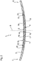
- Figure 1 shows a perspective view of a leaf spring device 1 according to the invention.
- the leaf spring device 1 has a first spring leaf 2 and a further spring leaf 3.
- the further spring leaf 3 is designed as a second spring leaf.
- the leaf spring device 1 thus has two spring leaves, namely the first spring leaf 2 and the further spring leaf 3.
- the first spring leaf 2 and the further spring leaf 3 are each formed from a fiber-reinforced plastic, in this exemplary embodiment from a glass fiber plastic.
- the further spring leaf 3 is shorter than the first spring leaf 2 with respect to the longitudinal extent of the leaf spring device 1.
- both the first spring leaf 2 and the further spring leaf 3 are curved, in particular in an unloaded state.
- the further spring leaf 3 is arranged in a receiving space 4 of the first spring leaf 2.
- the further spring leaf 3 is thus arranged within the first spring leaf 2 or integrated into the first spring leaf 2.
- the receiving space 4 is designed as a through opening in the first spring leaf 2.
- the receiving space 4 extends from a first side 5 of the first spring leaf to a second side 6 of the first spring leaf 2 facing away from the first side 5.
- the leaf spring device 1 is designed as a longitudinal leaf spring.
- the receiving space 4 or a longitudinal axis of the through opening forming the receiving space 4 extends in a mounted state (not shown here) of the leaf spring device 1 in a vehicle and / or in a chassis transversely or at right angles to a vertical axis of the vehicle.
- the first spring leaf 2 has a first end 7 and a second end 8 facing away from the first end 7.
- the two ends 7, 8 are designed as free ends.
- the leaf spring device 1 can be fastened to a vehicle carrier, vehicle frame and / or vehicle body by means of two fastening devices facing away from one another, each in the region of the end 7 or 8 and not shown here.
- Figure 2 shows a side view of the leaf spring device 1 according to the invention Figure 1 .
- the spring leaf 2, the further spring leaf 3 and the receiving space 4 are mirror-symmetrical to a central plane 9.
- the central plane 9 is vertically aligned in the assembled state of the leaf spring device 1.
- the central plane 9 also extends at right angles to the longitudinal extension of the leaf spring device 1.
- a central plane can extend exclusively parallel to the longitudinal extension of the leaf spring device 1.
- the leaf spring device 1 is designed as a longitudinal leaf spring
- the central plane 9 also extends at right angles to a longitudinal axis of the vehicle in the assembled state.
- the first leaf spring device 1 is curved.
- the leaf spring device 1 or the first spring leaf 2 has a concave outer side 10 and a convex outer side 11.
- the further spring leaf 3 has a first end region 12 and a second end region 13 facing away from it.
- the first end region 12 faces the first end 7 of the first spring leaf 2 and the second end region 13 faces the second end 8 of the first spring leaf 2, but is spaced from this end 7, 8 in each case.
- the further spring leaf 3 has a central region 14 in the middle between the two end regions 12, 13.
- An elastic material 15 is arranged between the first spring leaf 2 and the further spring leaf 3.
- the elastic material 15 is designed as an elastomer material.
- the elastic material 15 contacts on the one hand an inner circumference 16 of the receiving space 4 and on the other hand an outer circumference 17 of the further spring leaf 3.
- the inner circumference 16 is formed by means of a convexly curved inner side 18, a concave curved inner side 19 and the end sections 20, 21 of the receiving space 4 connecting the two inner sides 18, 19 to one another.
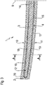
- Figure 3 shows a section of the side view of the leaf spring device 1 according to the invention Figure 2 .
- the first end region 12 of the further spring leaf 3 is arranged at a smaller distance from the concavely curved inner side 19 than from the convexly curved inner side 18.
- An analogous arrangement results for the mirror-symmetrically designed end region 13 according to FIG Figure 2 .
- the central region 14 is arranged at a smaller distance from the convexly curved inner side 18 than from the concavely curved inner side 19.
- more elastic material 15 is arranged in the regions with a greater distance between the outer circumference 17 of the further spring leaf 3 and the inner circumference 16 of the first spring leaf 2 than in the regions with a smaller distance.
- Figure 4 shows a cross section AA of the leaf spring device 1 according to the invention Figure 3 .
- the receiving space 4 is designed as a through opening which extends from the first side 5 to the second side 6 of the first spring leaf 2.
- the receiving space is completely filled by means of the further spring leaf 3 and the elastic material 15.
- the further spring leaf 3 and the elastic material 15 are flush with the sides 5 and 6, respectively.
- the elastic material can have an inwardly facing or concave indentation.
- the elastic material 15 is increasingly deformed with increasing spring loading and, following this or at the same time, the additional spring leaf 3 is increasingly loaded.
- the spring load acts from the convex outer side 10 in the direction of the concave outer side 11.
- the spring load is directed in the vertical direction from the bottom upwards or the direction of the vehicle vertical axis.
- the first spring leaf 2, the further spring leaf 3, the receiving space 4 and / or the elastic material 15 can be designed or adapted in a suitable manner.
- This design or adaptation can relate to the shape, the contour or material properties.
Landscapes
- Engineering & Computer Science (AREA)
- General Engineering & Computer Science (AREA)
- Mechanical Engineering (AREA)
- Springs (AREA)
- Vehicle Body Suspensions (AREA)
Claims (14)
- Dispositif de ressort à lame pour un véhicule, comprenant une première lame de ressort (2) et au moins une lame de ressort supplémentaire (3), la première lame de ressort (2) et la lame de ressort supplémentaire (3) coopérant pour réaliser une suspension à ressort progressive, la première lame de ressort (2) présentant un espace de réception (4) et la lame de ressort supplémentaire (3) étant disposée dans l'espace de réception (4), caractérisé en ce qu'un matériau élastique (15) est disposé dans l'espace de réception (4) et entre la première lame de ressort (2) et la lame de ressort supplémentaire (3).
- Dispositif de ressort à lame selon la revendication 1, caractérisé en ce que le matériau élastique (15) s'applique d'une part contre une périphérie intérieure (16) de l'espace de réception (4) et d'autre part contre une périphérie extérieure (17) de la lame de ressort supplémentaire (3).
- Dispositif de ressort à lame selon l'une quelconque des revendications 1 et 2, caractérisé en ce que la première lame de ressort (2) et/ou la lame de ressort supplémentaire (3) sont formées d'un plastique renforcé par des fibres, en particulier, la première lame de ressort (2) est formée d'un premier plastique renforcé par des fibres et la lame de ressort supplémentaire (3) est formée d'un plastique renforcé par des fibres supplémentaire différent du premier plastique renforcé par des fibres, de préférence le premier plastique renforcé par des fibres, le plastique renforcé par des fibres supplémentaire et/ou un matériau élastique sont réalisés et/ou sélectionnés de manière ajustée les uns aux autres pour réaliser une caractéristique de ressort prédéfinie.
- Dispositif de ressort à lame selon la revendication 2 ou 3, caractérisé en ce que la première lame de ressort (2), la lame de ressort supplémentaire (3) et le matériau élastique (15) sont réalisés de manière à obtenir une suspension à ressort progressive et/ou une caractéristique de ressort progressive, le matériau élastique (15), à partir d'un état non sollicité du dispositif de ressort à lame (1), se déformant et/ou étant comprimé de manière croissante avec l'augmentation de la charge du ressort et la lame de ressort supplémentaire (3) étant de ce fait sollicitée de manière croissante.
- Dispositif de ressort à lame selon l'une quelconque des revendications précédentes, caractérisé en ce que la lame de ressort supplémentaire (3) et/ou un matériau élastique (15) sont disposés complètement à l'intérieur de la première lame de ressort (2), en particulier, l'espace de réception (4) est réalisé sous forme de cavité dans la première lame de ressort (2), de préférence la lame de ressort supplémentaire (3) et/ou le matériau élastique (15) sont complètement entourés par la première lame de ressort (2).
- Dispositif de ressort à lame selon l'une quelconque des revendications précédentes, caractérisé en ce que l'espace de réception (4), en tant qu'ouverture de passage, s'étend depuis un premier côté (5) de la première lame de ressort (2) jusqu'à un deuxième côté (6) de la première lame de ressort (2) opposé au premier côté (5), en particulier l'espace de réception (4), dans un état du dispositif de ressort à lame (1) monté dans le véhicule, s'étend transversalement ou à angle droit par rapport à un axe vertical du véhicule.
- Dispositif de ressort à lame selon l'une quelconque des revendications précédentes, caractérisé en ce que la première lame de ressort (2) et/ou la lame de ressort supplémentaire (3) sont réalisées avec une symétrie spéculaire par rapport à un plan médian (9), de préférence le plan médian (9) s'étend parallèlement ou à angle droit par rapport à un axe longitudinal du dispositif de ressort à lame (1), en particulier l'axe longitudinal du dispositif de ressort à lame (1) s'étend à travers deux dispositifs de fixation terminaux opposés l'un à l'autre pour fixer le dispositif de ressort à lame (1) à un support du véhicule et/ou à une carrosserie du véhicule.
- Dispositif de ressort à lame selon l'une quelconque des revendications précédentes, caractérisé en ce que la première lame de ressort (2), la lame de ressort supplémentaire (3) et/ou l'espace de réception (4), en particulier dans un état non sollicité du dispositif de ressort à lame (1), présentent une configuration courbe ou cintrée.
- Dispositif de ressort à lame selon l'une quelconque des revendications précédentes, caractérisé en ce que l'espace de réception (4), en particulier dans un état non sollicité du dispositif de ressort (1), présente un côté intérieur de courbure convexe (18) et un côté intérieur de courbure concave (19), le côté intérieur de courbure convexe (18) et le côté intérieur de courbure concave (19) s'étendant dans la direction longitudinale de la première lame de ressort (2), de préférence le côté intérieur de courbure convexe (18) et le côté intérieur de courbure concave (19) étant disposés à l'opposé l'un de l'autre et/ou en regard l'un de l'autre.
- Dispositif de ressort à lame selon la revendication 9, caractérisé en ce que deux régions d'extrémité opposées l'une à l'autre (12, 13) de la lame de ressort supplémentaire (3), en particulier dans un état non sollicité du dispositif de ressort à lame (1), sont disposées à plus faible distance du côté intérieur de courbure concave (19) que du côté intérieur de courbure convexe (18), de préférence une première région d'extrémité (12) de la lame de ressort supplémentaire (3) est tournée vers une première extrémité (7) de la première lame de ressort (2) et une deuxième région d'extrémité (13) de la lame de ressort supplémentaire (3) est tournée vers une deuxième extrémité (8) de la première lame de ressort (2).
- Dispositif de ressort à lame selon la revendication 9 ou 10, caractérisé en ce qu'une région centrale (14) de la lame de ressort supplémentaire (3), en particulier dans un état non sollicité du dispositif de ressort à lame (1), est disposée à plus faible distance du côté intérieur de courbure convexe (18) que du côté intérieur de courbure concave (19), de préférence la région centrale (14) est disposée au centre entre deux régions d'extrémité (12, 13) de la lame de ressort supplémentaire (3).
- Procédé de fabrication d'un dispositif de ressort à lame selon l'une quelconque des revendications précédentes, dans lequel une première lame de ressort (2) et au moins une lame de ressort supplémentaire (3) sont fabriquées, la première lame de ressort (2) et la lame de ressort supplémentaire (3) coopèrent pour obtenir une suspension à ressort progressive et/ou une caractéristique de ressort progressive, et la première lame de ressort (2) présente un espace de réception (4) et la lame de ressort supplémentaire (3) est disposée dans l'espace de réception (4), un matériau élastique (15) étant disposé dans l'espace de réception et entre la première lame de ressort (2) et la lame de ressort supplémentaire (3) .
- Procédé selon la revendication 12, caractérisé en ce que la première lame de ressort (2), la lame de ressort supplémentaire (3) et le matériau élastique (15) sont fabriqués sous forme de couches et/ou sous forme de strates, de préférence le dispositif de ressort à lame (1) étant construit et/ou fabriqué sous forme de strates et/ou sous forme de couches.
- Utilisation d'un dispositif de ressort à lame (1) selon l'une quelconque des revendications 1 à 11, en tant que ressort à lame longitudinal ou en tant que ressort à lame transversal dans un châssis d'un véhicule ou d'un véhicule automobile.
Applications Claiming Priority (1)
| Application Number | Priority Date | Filing Date | Title |
|---|---|---|---|
| DE102018205218.2A DE102018205218A1 (de) | 2018-04-06 | 2018-04-06 | Blattfedereinrichtung für ein Fahrzeug und Verfahren zum Herstellen einer solchen Blattfedereinrichtung |
Publications (2)
| Publication Number | Publication Date |
|---|---|
| EP3550171A1 EP3550171A1 (fr) | 2019-10-09 |
| EP3550171B1 true EP3550171B1 (fr) | 2020-06-17 |
Family
ID=65724219
Family Applications (1)
| Application Number | Title | Priority Date | Filing Date |
|---|---|---|---|
| EP19161167.2A Not-in-force EP3550171B1 (fr) | 2018-04-06 | 2019-03-07 | Dispositif de ressort à lame pour véhicule et procédé de fabrication d'un tel dispositif de ressort à lame |
Country Status (3)
| Country | Link |
|---|---|
| US (1) | US20190309814A1 (fr) |
| EP (1) | EP3550171B1 (fr) |
| DE (1) | DE102018205218A1 (fr) |
Families Citing this family (7)
| Publication number | Priority date | Publication date | Assignee | Title |
|---|---|---|---|---|
| DE102019129581A1 (de) * | 2019-11-04 | 2021-05-06 | Danto Invention Gmbh & Co. Kg | Biegefederelement aus einem Faserkunststoffverbundmaterial |
| CN110978927A (zh) * | 2019-12-21 | 2020-04-10 | 山东雷帕得汽车技术股份有限公司 | 一种自卸车用高应力少片簧 |
| EP3875367B1 (fr) * | 2020-03-02 | 2023-08-02 | Safran Landing Systems UK Limited | Ensemble train d'atterrissage d'aéronef |
| USD1042958S1 (en) | 2021-05-25 | 2024-09-17 | The Gillette Company Llc | Razor handle |
| USD1046291S1 (en) | 2021-05-25 | 2024-10-08 | The Gillette Company Llc | Razor handle |
| USD1046290S1 (en) | 2021-05-25 | 2024-10-08 | The Gillette Company Llc | Razor handle |
| CN116221309B (zh) * | 2023-03-09 | 2025-04-29 | 中国重汽集团济南动力有限公司 | 一种复合材料板簧防护装置 |
Family Cites Families (15)
| Publication number | Priority date | Publication date | Assignee | Title |
|---|---|---|---|---|
| GB239164A (en) * | 1924-08-30 | 1925-11-26 | Gaston Libert | Improvements in or relating to laminated springs |
| FR1008358A (fr) * | 1949-01-19 | 1952-05-16 | Ressort à lames à rigidité variable avec la charge, et à amortissement automatique des oscillations | |
| US2698750A (en) * | 1952-04-28 | 1955-01-04 | Nicosia Chris | Rust-proofed automobile spring |
| JPS5776368A (en) * | 1980-10-31 | 1982-05-13 | Toyota Motor Corp | Leaf spring made of fiber-reinforced plastics |
| US4688778A (en) * | 1982-10-01 | 1987-08-25 | Isosport Verbundbauteile Ges.M.B.H. | Plastic leaf spring |
| JPS60125427A (ja) * | 1983-12-08 | 1985-07-04 | Nhk Spring Co Ltd | Frp板ばね |
| JPS61119827A (ja) * | 1984-11-14 | 1986-06-07 | Nhk Spring Co Ltd | Frpテ−パ−板ばね |
| JPS61144437A (ja) * | 1984-12-14 | 1986-07-02 | Nhk Spring Co Ltd | Frpテ−パ−板ばね |
| US6660114B2 (en) * | 2000-01-24 | 2003-12-09 | Pacific Coast Composites | Method for producing a hybrid leaf spring |
| US6461455B1 (en) * | 2000-01-24 | 2002-10-08 | Pacific Coast Composites | Method of producing a hybrid leaf spring |
| US20070040309A1 (en) * | 2005-08-19 | 2007-02-22 | Tolani Nirmal M | Light weight spring for vehicle suspension and method of manufacture |
| DE102009058170A1 (de) * | 2009-12-15 | 2011-06-22 | Benteler SGL GmbH & Co. KG, 33102 | Blattfederanordnung |
| DE102010015951A1 (de) | 2010-03-12 | 2011-09-15 | Muhr Und Bender Kg | Blattfeder für Kraftfahrzeuge |
| EP2971843A4 (fr) * | 2013-03-15 | 2016-11-16 | Gordon Holdings Inc | Ressort à lames composite à haute résistance, de poids léger et procédé de fabrication |
| DE102016215938B4 (de) * | 2016-08-25 | 2019-11-28 | Zf Friedrichshafen Ag | Verfahren zur Herstellung einer Blattfeder, sowie Blattfeder und Fahrwerk für ein Kraftfahrzeug |
-
2018
- 2018-04-06 DE DE102018205218.2A patent/DE102018205218A1/de not_active Ceased
-
2019
- 2019-03-07 EP EP19161167.2A patent/EP3550171B1/fr not_active Not-in-force
- 2019-04-04 US US16/374,975 patent/US20190309814A1/en not_active Abandoned
Non-Patent Citations (1)
| Title |
|---|
| None * |
Also Published As
| Publication number | Publication date |
|---|---|
| EP3550171A1 (fr) | 2019-10-09 |
| US20190309814A1 (en) | 2019-10-10 |
| DE102018205218A1 (de) | 2019-10-10 |
Similar Documents
| Publication | Publication Date | Title |
|---|---|---|
| EP3550171B1 (fr) | Dispositif de ressort à lame pour véhicule et procédé de fabrication d'un tel dispositif de ressort à lame | |
| EP2734390B1 (fr) | Bras de suspension à quatre points | |
| EP2470387B1 (fr) | Dispositif de montage pour un ressort à lame latéralement orienté | |
| WO2011110611A2 (fr) | Ressort à lame pour véhicules automobiles | |
| DE102009028893A1 (de) | Lagervorrichtung einer im Bereich einer Fahrzeugachse eines Fahrzeuges montierbaren Querblattfeder | |
| EP2990684B1 (fr) | Élément à ressort de flexion constitué d'un matériau composite à base de fibres synthétiques | |
| DE102011077336A1 (de) | Radaufhängungselement, umfassend zumindest eine Tragstruktur und einen Lenker | |
| AT516366B1 (de) | Feder für Radaufhängung und Radaufhängung | |
| DE102012009567A1 (de) | Achsträgeranordnung an einem Fahrzeug,insbesondere an einem Kraftfahrzeug | |
| DE102008008246A1 (de) | Buchsenlager mit verringertem Bauraumbedarf | |
| DE102018205215B4 (de) | Blattfedereinrichtung für ein Fahrzeug, Fahrwerk mit einer solchen Blattfedereinrichtung sowie ein Verfahren zum Herstellen einer solchen Blattfedereinrichtung und/oder eines solchen Fahrwerks | |
| DE102010061649A1 (de) | Blattfederelement | |
| WO2019206588A1 (fr) | Élément ressort | |
| DE102018208298B4 (de) | Koppelstange, Radaufhängung und Verfahren zur Herstellung einer Koppelstange | |
| DE102017206020A1 (de) | Blattfederanordnung für Kraftfahrzeuge | |
| EP3550172A1 (fr) | Support de ressort à lame destiné au raccordement d'un ressort à lame à un essieu et une suspension dotée d'un tel support de ressort à lame | |
| DE3637281A1 (de) | Am rahmen eines fahrgestells befestigbarer federbock | |
| WO2013079480A1 (fr) | Dispositif à ressort hélicoïdal pour un véhicule | |
| DE102020201607A1 (de) | Verfahren zum Herstellen eines Stabilisators für ein Fahrwerk eines Fahrzeugs sowie ein solcher Stabilisator | |
| DE202016103195U1 (de) | Fahrzeugkomponente mit einem Anbindungsbereich zur elastischen Anbindung einer anderen Komponente | |
| EP3524449B1 (fr) | Partie de suspension d'un véhicule automobile ainsi que procédé de fabrication d'une partie de suspension | |
| DE102020201326A1 (de) | Verfahren zum Herstellen eines Stabilisators für ein Fahrwerk eines Fahrzeugs | |
| EP3079970B1 (fr) | Ensemble composé d'un élément de châssis, d'un élément d'assemblage et d'un élément structural fixé à l'élément d'assemblage | |
| DE102019005356B4 (de) | Blattfeder mit Abstandhalter | |
| DE102017218795A1 (de) | Achsaufhängung |
Legal Events
| Date | Code | Title | Description |
|---|---|---|---|
| PUAI | Public reference made under article 153(3) epc to a published international application that has entered the european phase |
Free format text: ORIGINAL CODE: 0009012 |
|
| STAA | Information on the status of an ep patent application or granted ep patent |
Free format text: STATUS: THE APPLICATION HAS BEEN PUBLISHED |
|
| AK | Designated contracting states |
Kind code of ref document: A1 Designated state(s): AL AT BE BG CH CY CZ DE DK EE ES FI FR GB GR HR HU IE IS IT LI LT LU LV MC MK MT NL NO PL PT RO RS SE SI SK SM TR |
|
| AX | Request for extension of the european patent |
Extension state: BA ME |
|
| STAA | Information on the status of an ep patent application or granted ep patent |
Free format text: STATUS: REQUEST FOR EXAMINATION WAS MADE |
|
| 17P | Request for examination filed |
Effective date: 20191009 |
|
| RIC1 | Information provided on ipc code assigned before grant |
Ipc: F16F 1/368 20060101ALI20191203BHEP Ipc: F16F 1/22 20060101AFI20191203BHEP |
|
| GRAP | Despatch of communication of intention to grant a patent |
Free format text: ORIGINAL CODE: EPIDOSNIGR1 |
|
| STAA | Information on the status of an ep patent application or granted ep patent |
Free format text: STATUS: GRANT OF PATENT IS INTENDED |
|
| INTG | Intention to grant announced |
Effective date: 20200110 |
|
| GRAS | Grant fee paid |
Free format text: ORIGINAL CODE: EPIDOSNIGR3 |
|
| GRAA | (expected) grant |
Free format text: ORIGINAL CODE: 0009210 |
|
| STAA | Information on the status of an ep patent application or granted ep patent |
Free format text: STATUS: THE PATENT HAS BEEN GRANTED |
|
| AK | Designated contracting states |
Kind code of ref document: B1 Designated state(s): AL AT BE BG CH CY CZ DE DK EE ES FI FR GB GR HR HU IE IS IT LI LT LU LV MC MK MT NL NO PL PT RO RS SE SI SK SM TR |
|
| REG | Reference to a national code |
Ref country code: GB Ref legal event code: FG4D Free format text: NOT ENGLISH |
|
| REG | Reference to a national code |
Ref country code: CH Ref legal event code: EP |
|
| REG | Reference to a national code |
Ref country code: IE Ref legal event code: FG4D Free format text: LANGUAGE OF EP DOCUMENT: GERMAN |
|
| REG | Reference to a national code |
Ref country code: DE Ref legal event code: R096 Ref document number: 502019000059 Country of ref document: DE |
|
| REG | Reference to a national code |
Ref country code: AT Ref legal event code: REF Ref document number: 1281678 Country of ref document: AT Kind code of ref document: T Effective date: 20200715 |
|
| PG25 | Lapsed in a contracting state [announced via postgrant information from national office to epo] |
Ref country code: SE Free format text: LAPSE BECAUSE OF FAILURE TO SUBMIT A TRANSLATION OF THE DESCRIPTION OR TO PAY THE FEE WITHIN THE PRESCRIBED TIME-LIMIT Effective date: 20200617 Ref country code: GR Free format text: LAPSE BECAUSE OF FAILURE TO SUBMIT A TRANSLATION OF THE DESCRIPTION OR TO PAY THE FEE WITHIN THE PRESCRIBED TIME-LIMIT Effective date: 20200918 Ref country code: FI Free format text: LAPSE BECAUSE OF FAILURE TO SUBMIT A TRANSLATION OF THE DESCRIPTION OR TO PAY THE FEE WITHIN THE PRESCRIBED TIME-LIMIT Effective date: 20200617 Ref country code: NO Free format text: LAPSE BECAUSE OF FAILURE TO SUBMIT A TRANSLATION OF THE DESCRIPTION OR TO PAY THE FEE WITHIN THE PRESCRIBED TIME-LIMIT Effective date: 20200917 Ref country code: LT Free format text: LAPSE BECAUSE OF FAILURE TO SUBMIT A TRANSLATION OF THE DESCRIPTION OR TO PAY THE FEE WITHIN THE PRESCRIBED TIME-LIMIT Effective date: 20200617 |
|
| REG | Reference to a national code |
Ref country code: LT Ref legal event code: MG4D |
|
| REG | Reference to a national code |
Ref country code: NL Ref legal event code: MP Effective date: 20200617 |
|
| PG25 | Lapsed in a contracting state [announced via postgrant information from national office to epo] |
Ref country code: LV Free format text: LAPSE BECAUSE OF FAILURE TO SUBMIT A TRANSLATION OF THE DESCRIPTION OR TO PAY THE FEE WITHIN THE PRESCRIBED TIME-LIMIT Effective date: 20200617 Ref country code: RS Free format text: LAPSE BECAUSE OF FAILURE TO SUBMIT A TRANSLATION OF THE DESCRIPTION OR TO PAY THE FEE WITHIN THE PRESCRIBED TIME-LIMIT Effective date: 20200617 Ref country code: BG Free format text: LAPSE BECAUSE OF FAILURE TO SUBMIT A TRANSLATION OF THE DESCRIPTION OR TO PAY THE FEE WITHIN THE PRESCRIBED TIME-LIMIT Effective date: 20200917 Ref country code: HR Free format text: LAPSE BECAUSE OF FAILURE TO SUBMIT A TRANSLATION OF THE DESCRIPTION OR TO PAY THE FEE WITHIN THE PRESCRIBED TIME-LIMIT Effective date: 20200617 |
|
| PG25 | Lapsed in a contracting state [announced via postgrant information from national office to epo] |
Ref country code: NL Free format text: LAPSE BECAUSE OF FAILURE TO SUBMIT A TRANSLATION OF THE DESCRIPTION OR TO PAY THE FEE WITHIN THE PRESCRIBED TIME-LIMIT Effective date: 20200617 Ref country code: AL Free format text: LAPSE BECAUSE OF FAILURE TO SUBMIT A TRANSLATION OF THE DESCRIPTION OR TO PAY THE FEE WITHIN THE PRESCRIBED TIME-LIMIT Effective date: 20200617 |
|
| PG25 | Lapsed in a contracting state [announced via postgrant information from national office to epo] |
Ref country code: RO Free format text: LAPSE BECAUSE OF FAILURE TO SUBMIT A TRANSLATION OF THE DESCRIPTION OR TO PAY THE FEE WITHIN THE PRESCRIBED TIME-LIMIT Effective date: 20200617 Ref country code: CZ Free format text: LAPSE BECAUSE OF FAILURE TO SUBMIT A TRANSLATION OF THE DESCRIPTION OR TO PAY THE FEE WITHIN THE PRESCRIBED TIME-LIMIT Effective date: 20200617 Ref country code: IT Free format text: LAPSE BECAUSE OF FAILURE TO SUBMIT A TRANSLATION OF THE DESCRIPTION OR TO PAY THE FEE WITHIN THE PRESCRIBED TIME-LIMIT Effective date: 20200617 Ref country code: SM Free format text: LAPSE BECAUSE OF FAILURE TO SUBMIT A TRANSLATION OF THE DESCRIPTION OR TO PAY THE FEE WITHIN THE PRESCRIBED TIME-LIMIT Effective date: 20200617 Ref country code: EE Free format text: LAPSE BECAUSE OF FAILURE TO SUBMIT A TRANSLATION OF THE DESCRIPTION OR TO PAY THE FEE WITHIN THE PRESCRIBED TIME-LIMIT Effective date: 20200617 Ref country code: ES Free format text: LAPSE BECAUSE OF FAILURE TO SUBMIT A TRANSLATION OF THE DESCRIPTION OR TO PAY THE FEE WITHIN THE PRESCRIBED TIME-LIMIT Effective date: 20200617 Ref country code: PT Free format text: LAPSE BECAUSE OF FAILURE TO SUBMIT A TRANSLATION OF THE DESCRIPTION OR TO PAY THE FEE WITHIN THE PRESCRIBED TIME-LIMIT Effective date: 20201019 |
|
| PG25 | Lapsed in a contracting state [announced via postgrant information from national office to epo] |
Ref country code: PL Free format text: LAPSE BECAUSE OF FAILURE TO SUBMIT A TRANSLATION OF THE DESCRIPTION OR TO PAY THE FEE WITHIN THE PRESCRIBED TIME-LIMIT Effective date: 20200617 Ref country code: SK Free format text: LAPSE BECAUSE OF FAILURE TO SUBMIT A TRANSLATION OF THE DESCRIPTION OR TO PAY THE FEE WITHIN THE PRESCRIBED TIME-LIMIT Effective date: 20200617 Ref country code: IS Free format text: LAPSE BECAUSE OF FAILURE TO SUBMIT A TRANSLATION OF THE DESCRIPTION OR TO PAY THE FEE WITHIN THE PRESCRIBED TIME-LIMIT Effective date: 20201017 |
|
| REG | Reference to a national code |
Ref country code: DE Ref legal event code: R097 Ref document number: 502019000059 Country of ref document: DE |
|
| PLBE | No opposition filed within time limit |
Free format text: ORIGINAL CODE: 0009261 |
|
| STAA | Information on the status of an ep patent application or granted ep patent |
Free format text: STATUS: NO OPPOSITION FILED WITHIN TIME LIMIT |
|
| PG25 | Lapsed in a contracting state [announced via postgrant information from national office to epo] |
Ref country code: DK Free format text: LAPSE BECAUSE OF FAILURE TO SUBMIT A TRANSLATION OF THE DESCRIPTION OR TO PAY THE FEE WITHIN THE PRESCRIBED TIME-LIMIT Effective date: 20200617 |
|
| 26N | No opposition filed |
Effective date: 20210318 |
|
| PG25 | Lapsed in a contracting state [announced via postgrant information from national office to epo] |
Ref country code: MC Free format text: LAPSE BECAUSE OF FAILURE TO SUBMIT A TRANSLATION OF THE DESCRIPTION OR TO PAY THE FEE WITHIN THE PRESCRIBED TIME-LIMIT Effective date: 20200617 |
|
| REG | Reference to a national code |
Ref country code: BE Ref legal event code: MM Effective date: 20210331 |
|
| PG25 | Lapsed in a contracting state [announced via postgrant information from national office to epo] |
Ref country code: FR Free format text: LAPSE BECAUSE OF NON-PAYMENT OF DUE FEES Effective date: 20210331 Ref country code: LU Free format text: LAPSE BECAUSE OF NON-PAYMENT OF DUE FEES Effective date: 20210307 Ref country code: IE Free format text: LAPSE BECAUSE OF NON-PAYMENT OF DUE FEES Effective date: 20210307 |
|
| PG25 | Lapsed in a contracting state [announced via postgrant information from national office to epo] |
Ref country code: BE Free format text: LAPSE BECAUSE OF NON-PAYMENT OF DUE FEES Effective date: 20210331 |
|
| REG | Reference to a national code |
Ref country code: CH Ref legal event code: PL |
|
| PG25 | Lapsed in a contracting state [announced via postgrant information from national office to epo] |
Ref country code: LI Free format text: LAPSE BECAUSE OF NON-PAYMENT OF DUE FEES Effective date: 20220331 Ref country code: CH Free format text: LAPSE BECAUSE OF NON-PAYMENT OF DUE FEES Effective date: 20220331 |
|
| PG25 | Lapsed in a contracting state [announced via postgrant information from national office to epo] |
Ref country code: CY Free format text: LAPSE BECAUSE OF FAILURE TO SUBMIT A TRANSLATION OF THE DESCRIPTION OR TO PAY THE FEE WITHIN THE PRESCRIBED TIME-LIMIT Effective date: 20200617 |
|
| P01 | Opt-out of the competence of the unified patent court (upc) registered |
Effective date: 20230528 |
|
| PG25 | Lapsed in a contracting state [announced via postgrant information from national office to epo] |
Ref country code: HU Free format text: LAPSE BECAUSE OF FAILURE TO SUBMIT A TRANSLATION OF THE DESCRIPTION OR TO PAY THE FEE WITHIN THE PRESCRIBED TIME-LIMIT; INVALID AB INITIO Effective date: 20190307 |
|
| PG25 | Lapsed in a contracting state [announced via postgrant information from national office to epo] |
Ref country code: SI Free format text: LAPSE BECAUSE OF FAILURE TO SUBMIT A TRANSLATION OF THE DESCRIPTION OR TO PAY THE FEE WITHIN THE PRESCRIBED TIME-LIMIT Effective date: 20200617 |
|
| GBPC | Gb: european patent ceased through non-payment of renewal fee |
Effective date: 20230307 |
|
| PG25 | Lapsed in a contracting state [announced via postgrant information from national office to epo] |
Ref country code: GB Free format text: LAPSE BECAUSE OF NON-PAYMENT OF DUE FEES Effective date: 20230307 |
|
| PG25 | Lapsed in a contracting state [announced via postgrant information from national office to epo] |
Ref country code: GB Free format text: LAPSE BECAUSE OF NON-PAYMENT OF DUE FEES Effective date: 20230307 |
|
| PG25 | Lapsed in a contracting state [announced via postgrant information from national office to epo] |
Ref country code: MK Free format text: LAPSE BECAUSE OF FAILURE TO SUBMIT A TRANSLATION OF THE DESCRIPTION OR TO PAY THE FEE WITHIN THE PRESCRIBED TIME-LIMIT Effective date: 20200617 |
|
| PGFP | Annual fee paid to national office [announced via postgrant information from national office to epo] |
Ref country code: DE Payment date: 20231229 Year of fee payment: 6 |
|
| PG25 | Lapsed in a contracting state [announced via postgrant information from national office to epo] |
Ref country code: TR Free format text: LAPSE BECAUSE OF FAILURE TO SUBMIT A TRANSLATION OF THE DESCRIPTION OR TO PAY THE FEE WITHIN THE PRESCRIBED TIME-LIMIT Effective date: 20200617 |
|
| PG25 | Lapsed in a contracting state [announced via postgrant information from national office to epo] |
Ref country code: MT Free format text: LAPSE BECAUSE OF FAILURE TO SUBMIT A TRANSLATION OF THE DESCRIPTION OR TO PAY THE FEE WITHIN THE PRESCRIBED TIME-LIMIT Effective date: 20200617 |
|
| REG | Reference to a national code |
Ref country code: AT Ref legal event code: MM01 Ref document number: 1281678 Country of ref document: AT Kind code of ref document: T Effective date: 20240307 |
|
| PG25 | Lapsed in a contracting state [announced via postgrant information from national office to epo] |
Ref country code: AT Free format text: LAPSE BECAUSE OF NON-PAYMENT OF DUE FEES Effective date: 20240307 |
|
| REG | Reference to a national code |
Ref country code: DE Ref legal event code: R119 Ref document number: 502019000059 Country of ref document: DE |
|
| PG25 | Lapsed in a contracting state [announced via postgrant information from national office to epo] |
Ref country code: DE Free format text: LAPSE BECAUSE OF NON-PAYMENT OF DUE FEES Effective date: 20251001 |