EP3550171A1 - Dispositif de ressort à lame pour véhicule et procédé de fabrication d'un tel dispositif de ressort à lame - Google Patents
Dispositif de ressort à lame pour véhicule et procédé de fabrication d'un tel dispositif de ressort à lame Download PDFInfo
- Publication number
- EP3550171A1 EP3550171A1 EP19161167.2A EP19161167A EP3550171A1 EP 3550171 A1 EP3550171 A1 EP 3550171A1 EP 19161167 A EP19161167 A EP 19161167A EP 3550171 A1 EP3550171 A1 EP 3550171A1
- Authority
- EP
- European Patent Office
- Prior art keywords
- leaf
- spring
- spring leaf
- receiving space
- elastic material
- Prior art date
- Legal status (The legal status is an assumption and is not a legal conclusion. Google has not performed a legal analysis and makes no representation as to the accuracy of the status listed.)
- Granted
Links
Images

Classifications
-
- F—MECHANICAL ENGINEERING; LIGHTING; HEATING; WEAPONS; BLASTING
- F16—ENGINEERING ELEMENTS AND UNITS; GENERAL MEASURES FOR PRODUCING AND MAINTAINING EFFECTIVE FUNCTIONING OF MACHINES OR INSTALLATIONS; THERMAL INSULATION IN GENERAL
- F16F—SPRINGS; SHOCK-ABSORBERS; MEANS FOR DAMPING VIBRATION
- F16F1/00—Springs
- F16F1/02—Springs made of steel or other material having low internal friction; Wound, torsion, leaf, cup, ring or the like springs, the material of the spring not being relevant
- F16F1/18—Leaf springs
- F16F1/185—Leaf springs characterised by shape or design of individual leaves
-
- F—MECHANICAL ENGINEERING; LIGHTING; HEATING; WEAPONS; BLASTING
- F16—ENGINEERING ELEMENTS AND UNITS; GENERAL MEASURES FOR PRODUCING AND MAINTAINING EFFECTIVE FUNCTIONING OF MACHINES OR INSTALLATIONS; THERMAL INSULATION IN GENERAL
- F16F—SPRINGS; SHOCK-ABSORBERS; MEANS FOR DAMPING VIBRATION
- F16F1/00—Springs
- F16F1/36—Springs made of rubber or other material having high internal friction, e.g. thermoplastic elastomers
- F16F1/366—Springs made of rubber or other material having high internal friction, e.g. thermoplastic elastomers made of fibre-reinforced plastics, i.e. characterised by their special construction from such materials
- F16F1/368—Leaf springs
-
- B—PERFORMING OPERATIONS; TRANSPORTING
- B60—VEHICLES IN GENERAL
- B60G—VEHICLE SUSPENSION ARRANGEMENTS
- B60G11/00—Resilient suspensions characterised by arrangement, location or kind of springs
- B60G11/02—Resilient suspensions characterised by arrangement, location or kind of springs having leaf springs only
-
- F—MECHANICAL ENGINEERING; LIGHTING; HEATING; WEAPONS; BLASTING
- F16—ENGINEERING ELEMENTS AND UNITS; GENERAL MEASURES FOR PRODUCING AND MAINTAINING EFFECTIVE FUNCTIONING OF MACHINES OR INSTALLATIONS; THERMAL INSULATION IN GENERAL
- F16F—SPRINGS; SHOCK-ABSORBERS; MEANS FOR DAMPING VIBRATION
- F16F1/00—Springs
- F16F1/02—Springs made of steel or other material having low internal friction; Wound, torsion, leaf, cup, ring or the like springs, the material of the spring not being relevant
- F16F1/18—Leaf springs
- F16F1/22—Leaf springs with means for modifying the spring characteristic
-
- B—PERFORMING OPERATIONS; TRANSPORTING
- B60—VEHICLES IN GENERAL
- B60G—VEHICLE SUSPENSION ARRANGEMENTS
- B60G2202/00—Indexing codes relating to the type of spring, damper or actuator
- B60G2202/10—Type of spring
- B60G2202/11—Leaf spring
-
- F—MECHANICAL ENGINEERING; LIGHTING; HEATING; WEAPONS; BLASTING
- F16—ENGINEERING ELEMENTS AND UNITS; GENERAL MEASURES FOR PRODUCING AND MAINTAINING EFFECTIVE FUNCTIONING OF MACHINES OR INSTALLATIONS; THERMAL INSULATION IN GENERAL
- F16F—SPRINGS; SHOCK-ABSORBERS; MEANS FOR DAMPING VIBRATION
- F16F2228/00—Functional characteristics, e.g. variability, frequency-dependence
- F16F2228/14—Functional characteristics, e.g. variability, frequency-dependence progressive
-
- F—MECHANICAL ENGINEERING; LIGHTING; HEATING; WEAPONS; BLASTING
- F16—ENGINEERING ELEMENTS AND UNITS; GENERAL MEASURES FOR PRODUCING AND MAINTAINING EFFECTIVE FUNCTIONING OF MACHINES OR INSTALLATIONS; THERMAL INSULATION IN GENERAL
- F16F—SPRINGS; SHOCK-ABSORBERS; MEANS FOR DAMPING VIBRATION
- F16F2238/00—Type of springs or dampers
- F16F2238/02—Springs
- F16F2238/022—Springs leaf-like, e.g. of thin, planar-like metal
Definitions
- the invention relates to a leaf spring device for a vehicle having a first spring leaf and at least one further spring leaf, wherein the first spring leaf and the further spring leaf cooperate to realize a progressive suspension. Furthermore, the invention relates to a method for producing such a leaf spring device, wherein a first spring leaf and at least one further spring leaf are produced, and the first spring leaf and the further spring leaf for realizing a progressive suspension and / or spring characteristic cooperate. Finally, the invention relates to the use of such a leaf spring device as a longitudinal leaf spring or a transverse leaf spring in a chassis of a vehicle or motor vehicle.
- Such a leaf spring device is known from DE 10 2010 015 951 A1 known. Thereafter, a progressive course of a force-displacement characteristic is made possible when a leaf spring device is used, which is composed of a plurality of spring leaves, which are each suitably designed and connected to each other or arranged in a Federblattverbund.
- sheet metal spring devices it is known to use a plurality of spring leaves made of metal of different lengths and / or number to realize a progressive suspension.
- at least one of these spring leaves acts only from a certain or predetermined spring travel, whereby the rigidity of the leaf spring device is increased.
- Such an increasing stiffness of the leaf spring device and / or progressive suspension is required for example for vehicles of certain weight classes or vehicles with high payload. As a result, an almost constant body natural frequency can be ensured, which increases driving safety.
- a multileaf leaf spring device with at least one spring leaf made of a fiber-reinforced plastic there is a risk that in the region of a contact of the spring leaf of the fiber-reinforced plastic with the at least one further spring leaf comes to an undesirable damage.
- an entry of dirt particles and / or abrasion in the region of a contact surface of the spring leaf of the fiber-reinforced plastic with the other spring leaf can lead to undesirable damage to the leaf spring device, whereby the operability compromised and / or the service life of the leaf spring device can be reduced.
- an increasing stiffness and / or a progressive suspension in a multi-leaf leaf spring device made of a fiber-reinforced plastic composite, in particular fiberglass not readily feasible.
- the stiffness of the leaf spring device should increase or increase depending on the spring travel and / or spring load.
- an alternative embodiment is to be provided.
- the leaf spring device is designed for use in a vehicle and / or motor vehicle.
- the leaf spring device is arranged in a chassis of a vehicle and / or motor vehicle.
- the leaf spring device can be connected to an axle, a rigid axle, a wheel axle, a wheel carrier and / or a transverse link.
- the axle may be formed as a rear axle or as a front axle.
- the leaf spring device can be arranged in the longitudinal direction or in the transverse direction to the vehicle longitudinal axis.
- the leaf spring device has a first spring leaf and at least one further spring leaf.
- the leaf spring means at least two or more spring leaves exhibit.
- the leaf spring device can be constructed in two rows or Girblättrig.
- the further spring leaf is designed as a second spring leaf.
- the leaf spring device has a single first spring leaf and a single second spring leaf.
- the first spring leaf and the further spring leaf cooperate to realize a progressive suspension and / or progressive spring characteristic.
- a stiffness of the leaf spring device is increased from a predetermined spring load and / or with an increasing spring load.
- the stiffness may increase or increase continuously or exponentially, in particular as of the predetermined spring load.
- the first spring leaf has a receiving space, wherein the further spring leaf is arranged in the receiving space.
- the further spring leaf is arranged in the receiving space of the first spring leaf.
- the further spring leaf can be arranged within the first spring leaf.
- the receiving space may be referred to as an interior.
- the receiving space and / or the interior may be formed as a completely closed or open space.
- an elastic material is arranged in the receiving space and between the first spring leaf and the further spring leaf, in particular at least partially or at least partially.
- the first spring leaf and the other spring leaf are not directly adjacent to each other.
- the risk of undesired damage during operation of the leaf spring device is considerably reduced.
- the first spring leaf and the other spring leaf are due the elastic material connected together.
- the elastic material is located on the one hand on an inner circumference and / or an inner side of the receiving space and on the other hand on an outer circumference and / or an outer side of the further spring leaf, in particular at least partially.
- the elastic material may be firmly connected to the inner periphery of the receiving space and / or fixed to the outer periphery of the further spring leaf.
- the elastic material is an elastomeric material.
- An elastomer material may be an elastically deformable plastic and / or an elastically deformable rubber material.
- the elastic material an elastic plastic material or a rubber elastic material can be used.
- the elastic material is compressible, formed, for example, as a foamed elastomer.
- the elastic material is incompressible or incompressible.
- the elastic material and / or the elastomeric material may deform elastically under tensile and / or compressive loading. In particular, the elastic material may return to its original shape upon application of a force.
- the first spring leaf and / or the further spring leaf is formed from a fiber-reinforced plastic.
- the first spring leaf and / or the further spring leaf is made of a fiberglass plastic.
- the first spring leaf and / or the further spring leaf can each be formed from a plurality of fiber layers.
- the fiber layers are impregnated by means of a matrix material and / or connected to one another.
- the first spring leaf and the other spring leaf are each realized as a fiber-plastic composite.
- the first spring leaf may be formed of a first fiber-reinforced plastic and the other spring leaf of a different fiber-reinforced plastic deviating from the first fiber-reinforced plastic.
- the first fiber-reinforced plastic, the further fiber-reinforced plastic and / or an elastic material for realizing a predetermined spring characteristic, preferably a predetermined progressive suspension, designed and / or selected coordinated.
- the use of fiber reinforced Plastic for the formation of the first spring leaf, the other spring leaf and / or the leaf spring device allow, especially in comparison with a leaf spring device made of metal spring leaves, a weight saving.
- either the first spring leaf or the further spring leaf can be made of a fiber-reinforced plastic.
- the respective other spring leaf may be made of a different material, in particular of no fiber-reinforced plastic.
- the other material may be, for example, a metal.
- the first spring leaf, the further spring leaf and the elastic material for realizing a progressive suspension and / or a progressive spring characteristic are formed, starting from an unloaded state of the leaf spring means the elastic material with increasing spring load increasingly deformed and thereby increasingly the other spring leaf is loaded ,
- the elastic material is increasingly deformed, compressed and / or compacted with increasing spring loading.
- the rigidity of the leaf spring means can be increased with increasing spring load.
- a progressive suspension and / or spring characteristic can be realized.
- the elastic material preferably up to a predetermined spring load and / or acting spring force, at least partially decoupling of the first spring leaf from the other spring leaf.
- a bending load can not or only partially be transmitted from the first spring leaf via the elastic material to the further spring leaf. Only from the predetermined spring load and / or acting spring force, the other spring leaf can be loaded according to the first spring leaf to bending.
- the elastic material can not be deformed from the predetermined spring load and / or acting spring force, but with decreasing spring load and / or acting spring force only to return from a maximum deformed state in the direction of its initial shape.
- the further spring leaf and / or an elastic material is arranged completely within the first spring leaf, in particular in the receiving space.
- the receiving space may be formed as a cavity in the first spring leaf.
- the receiving space of the first spring leaf may be partially or completely filled by means of the further spring leaf and / or the elastic material.
- the further spring leaf and / or the elastic material may be completely surrounded by the first spring leaf.
- the further spring leaf can be completely surrounded or enclosed by the elastic material.
- the receiving space is formed as a passage opening.
- the passage opening may extend from a first side of the first spring leaf to a side facing away from the first side second side of the first spring leaf.
- the receiving space in a mounted in the vehicle and / or in a running gear state of the leaf spring device extends transversely or perpendicular to a vehicle vertical axis.
- the passage opening can be partially or completely filled by means of the further spring leaf and / or the elastic material.
- the first spring leaf and the further spring leaf can have the same width.
- the other spring leaf and / or the elastic material is visible from the outside. With increasing spring load, the elastic material can be deformed, pressed and / or pushed in the longitudinal direction of the passage opening. In this case, the elastic material can partially emerge from the passage opening and / or swell out.
- the first spring leaf and / or the further spring leaf is mirror-symmetrical to a median plane.
- the center plane may extend at right angles to a longitudinal axis or longitudinal extent of the leaf spring device and / or a vehicle longitudinal axis.
- the median plane may be parallel to a longitudinal axis or longitudinal extension of the leaf spring device and / or a vehicle longitudinal axis.
- the center plane is aligned in a mounted state of the leaf spring device in a chassis and / or in a vehicle vertically and / or in the direction of a vertical axis.
- the center plane may lie in a vertical plane and / or a vertical plane, or the center plane may coincide with a vertical plane and / or a vertical plane.
- the longitudinal axis of the leaf spring device can extend through two end fastening devices facing away from one another for fastening the leaf spring device to a vehicle carrier, vehicle stool, vehicle frame and / or vehicle body.
- two end fastening devices facing away from one another serve as bearings for the leaf spring device.
- the leaf spring device can be connected to an axis in a middle region, in particular centrally between the two end attachment devices.
- This axis may be formed as a wheel axle and / or rigid axle.
- the axle extends in a mounted state in a vehicle and / or in a chassis in a direction transverse or perpendicular to the vehicle longitudinal axis.
- the first spring leaf, the further spring leaf and / or the receiving space in particular in an unloaded state of the leaf spring device, a curved or curved shape.
- the curved or curved shape is directed towards an axis connected to the leaf spring device.
- the receiving space in particular in an unloaded state of the leaf spring device, has a convexly curved inner side and a concavely curved inner side.
- the convexly curved inner side may be regarded as a first inner side and the concavely curved inner side may be considered as a second inner side of the receiving space.
- the convexly curved inner side and the concavely curved inner side may extend in the longitudinal direction of the first spring leaf.
- the convexly curved inner side and the concavely curved inner side can merge into one another in end-side, in particular opposite, sections of the receiving space.
- the convex curved inner side and the concave curved inner side facing each other and / or arranged facing each other.
- the unloaded state of the leaf spring device may refer to an unmounted state of the leaf spring device with respect to the mounting in a chassis and / or vehicle.
- the unloaded state of the leaf spring means may refer to a state mounted on the vehicle and / or the chassis of the leaf spring device, wherein the leaf spring means acts on a spring load which corresponds to the maximum spring load in an empty state or in an unloaded state of the vehicle.
- two end regions of the further spring leaf facing away from one another, in particular in an unloaded state of the leaf spring device are arranged at a smaller distance to the concavely curved inner side than to the convexly curved inner side.
- a first end region of the further spring leaf may face a first end of the first spring leaf and a second end region of the further spring leaf may face a second end of the first spring leaf. Due to a suitable arrangement and / or design of the further spring leaf in the receiving space of the first spring leaf, the suspension properties of the leaf spring device can be influenced, predetermined or adjusted.
- a central region of the further spring leaf in particular in an unloaded state of the leaf spring device, is arranged at a smaller distance to the convexly curved inner side than to the concavely curved inner side.
- the distance between the inner circumference of the receiving space of the first spring leaf and the outer periphery of the further spring leaf over the longitudinal extent of the leaf spring means may be formed differently.
- the distance between the inner circumference of the receiving space and the outer circumference of the further spring leaf can be made constant and / or the same length over the length of the further spring leaf.
- the distance between the inner circumference of the receiving space and the outer periphery of the further spring leaf by means of the elastic material is complete or partially filled out.
- the middle region is arranged centrally between two end regions of the further spring leaf.
- a first spring leaf and at least one further spring leaf are produced.
- the first spring leaf and the further spring leaf cooperate to realize a progressive suspension and / or a progressive spring characteristic.
- the first spring leaf is formed such that it has a receiving space and the other spring leaf is arranged in the receiving space.
- an elastic material preferably an elastomer material
- the first spring leaf, the further spring leaf and the elastic material are produced like layers and / or layers.
- the leaf spring device is built up and / or layer-like and / or produced in a layered manner.
- the leaf spring device itself or as a whole can be realized in layers and / or constructed.
- a first and / or bottom portion of the first spring leaf can be constructed and / or manufactured.
- a first and / or lowermost portion of the elastic material is constructed and / or manufactured on the first and / or lowermost portion of the first spring leaf.
- the further spring leaf can be constructed and / or produced on the first and / or lowermost portion of the elastic material.
- a further and / or uppermost portion of the elastic material can be built up on the other spring leaf and / or produced.
- a further and / or uppermost portion of the first spring leaf can be constructed and / or manufactured on the further and / or uppermost portion of the elastic material.
- end regions of the first spring leaf can be constructed and / or manufactured. By means of these end regions, a first end and a second end of the first spring leaf can be realized.
- a fiber-reinforced plastic of the first spring leaf and the other spring leaf means consolidated and / or cured by a suitable procedure.
- This may, for example, be an RTM process (RTM: Resin Transfer Molding).
- first the first spring leaf and the further spring leaf are produced.
- the first spring leaf and then the further spring leaf can be produced first.
- first the further spring leaf and then the first spring leaf can be produced.
- the first spring leaf and the further spring leaf can be produced simultaneously or in parallel, in particular independently of one another.
- the elastic material is introduced between an inner circumference of the receiving space and an outer periphery of the further spring leaf for connecting the first spring leaf to the further spring leaf.
- first the elastic material can be applied to the outer circumference of the further spring leaf.
- the first spring leaf can be produced, so that the inner circumference of the receiving space of the first spring leaf rests against the elastic material.
- the further spring leaf in particular from individual fiber layers or fiber composite layers, can be produced.
- the elastic material is arranged on the further spring leaf.
- the elastic material may be formed as an elastomer insert.
- the first spring leaf, in particular from individual fiber layers or fiber composite layers can be produced.
- the first spring leaf, the further spring leaf and the elastic material can be produced simultaneously or in parallel, in particular independently of each other.
- a leaf spring device according to the invention as a longitudinal leaf spring or a transverse leaf spring in a chassis of a vehicle or motor vehicle.
- the leaf spring device produced according to the method according to the invention is a previously described leaf spring device according to the invention.
- the method is developed in accordance with all the embodiments explained in connection with the leaf spring device according to the invention described here.
- the leaf spring device described here can be developed in accordance with all the embodiments explained in connection with the method.
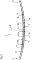
- FIG. 1 shows a perspective view of a leaf spring device according to the invention 1.
- the leaf spring device 1 comprises a first spring leaf 2 and a further spring leaf 3.
- the further spring leaf 3 is formed as a second spring leaf.
- the leaf spring device 1 thus has two spring leaves, namely the first spring leaf 2 and the further spring leaf 3.
- the first spring leaf 2 and the further spring leaf 3 are each formed from a fiber-reinforced plastic, in this embodiment of a fiberglass plastic.
- the further spring leaf 3 is in relation to the longitudinal extension of the leaf spring device 1 shorter than the first spring leaf 2.
- Both the first spring leaf 2 and the other spring leaf 3 are formed bent according to this example, in particular in an unloaded state.
- the further spring leaf 3 is arranged in a receiving space 4 of the first spring leaf 2.
- the further spring leaf 3 is disposed within the first spring leaf 2 and integrated into the first spring leaf 2.
- the receiving space 4 is formed as a through hole in the first spring sheet 2.
- the receiving space 4 extends from a first side 5 of the first spring leaf to a side facing away from the first side 5 second side 6 of the first spring leaf 2.
- the leaf spring device 1 is formed as a longitudinal leaf spring.
- the receiving space 4 or a longitudinal axis of the receiving space 4 forming through opening extends in a not shown here mounted state of the leaf spring device 1 in a vehicle and / or in a chassis transversely or perpendicular to a vehicle vertical axis.
- the first spring leaf 2 has a first end 7 and a second end 8 facing away from the first end 7.
- the two ends 7, 8 are formed as free ends.
- the leaf spring device 1 can be fastened to a vehicle carrier, vehicle frame and / or vehicle body by means of two fastening devices which are remote from one another and are respectively arranged in the region of the end 7 or 8 and not shown here.
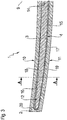
- FIG. 2 shows a side view of the leaf spring device 1 according to the invention FIG. 1 ,
- the spring leaf 2, the further spring leaf 3 and the receiving space 4 are mirror-symmetrical to a median plane 9.
- the center plane 9 is vertically aligned in an assembled state of the leaf spring device 1.
- the center plane 9 extends at right angles to the longitudinal extent of the leaf spring device 1.
- a center plane may extend only parallel to the longitudinal extent of the leaf spring device 1.
- the center plane 9 also extends in the mounted state at right angles to a Vehicle longitudinal axis.
- the first leaf spring device 1 is formed bent.
- the leaf spring device 1 or the first spring leaf 2 has a concave outer side 10 and a convex outer side 11.
- the further spring leaf 3 has a first end region 12 and a second end region 13 facing away from it.
- the first end region 12 faces the first end 7 of the first spring leaf 2 and the second end region 13 faces the second end 8 of the first spring leaf 2, but in each case is spaced from this end 7, 8.
- the further spring leaf 3 has a central region 14.
- an elastic material 15 is arranged between the first spring leaf 2 and the further spring leaf 3.
- the elastic material 15 is formed as an elastomeric material.
- the elastic material 15 contacts on the one hand an inner circumference 16 of the receiving space 4 and on the other hand an outer circumference 17 of the further spring leaf 3.
- the inner circumference 16 is formed by means of a convexly curved inner side 18, a concavely curved inner side 19 and the two inner sides 18, 19 interconnecting end-side sections 20, 21 of the receiving space 4.
- FIG. 3 shows a section of the side view of the leaf spring device 1 according to the invention FIG. 2 ,
- the first end region 12 of the further spring leaf 3 is arranged at a smaller distance to the concavely curved inner side 19 than to the convexly curved inner side 18.
- An analogous arrangement results for the mirror-symmetrical end region 13 according to FIG. 2 ,
- the central region 14 is arranged at a smaller distance to the convexly curved inner side 18 than to the concavely curved inner side 19.
- the central region 14 is arranged at a smaller distance to the convexly curved inner side 18 than to the concavely curved inner side 19.
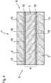
- FIG. 4 shows a cross section AA of the leaf spring device 1 according to the invention FIG. 3 , Good to see that the receiving space 4 is formed as a through hole extending from the first side 5 to the second side 6 of the first spring leaf 2.
- the receiving space is completely filled by means of the further spring leaf 3 and the elastic material 15.
- the further spring leaf 3 and the elastic material 15 terminate flush with the side 5 and 6, respectively.
- the elastic material may have an inwardly facing or concave indentation.
- the elastic material 15 is increasingly deformed with increasing spring load and then the following or at the same time increasingly loaded the further spring leaf 3.
- the spring load from the convex outer side 10 acts in the direction of the concave outer side 11.
- the spring load is directed in the vertical direction from bottom to top or direction of the vehicle's vertical axis.
- the first spring leaf 2, the further spring leaf 3, the receiving space 4 and / or the elastic material 15 can be suitably formed or adapted.
- This training or adaptation may relate to the shape, contour or material properties.
Landscapes
- Engineering & Computer Science (AREA)
- General Engineering & Computer Science (AREA)
- Mechanical Engineering (AREA)
- Springs (AREA)
- Vehicle Body Suspensions (AREA)
Applications Claiming Priority (1)
| Application Number | Priority Date | Filing Date | Title |
|---|---|---|---|
| DE102018205218.2A DE102018205218A1 (de) | 2018-04-06 | 2018-04-06 | Blattfedereinrichtung für ein Fahrzeug und Verfahren zum Herstellen einer solchen Blattfedereinrichtung |
Publications (2)
| Publication Number | Publication Date |
|---|---|
| EP3550171A1 true EP3550171A1 (fr) | 2019-10-09 |
| EP3550171B1 EP3550171B1 (fr) | 2020-06-17 |
Family
ID=65724219
Family Applications (1)
| Application Number | Title | Priority Date | Filing Date |
|---|---|---|---|
| EP19161167.2A Not-in-force EP3550171B1 (fr) | 2018-04-06 | 2019-03-07 | Dispositif de ressort à lame pour véhicule et procédé de fabrication d'un tel dispositif de ressort à lame |
Country Status (3)
| Country | Link |
|---|---|
| US (1) | US20190309814A1 (fr) |
| EP (1) | EP3550171B1 (fr) |
| DE (1) | DE102018205218A1 (fr) |
Cited By (1)
| Publication number | Priority date | Publication date | Assignee | Title |
|---|---|---|---|---|
| CN116221309A (zh) * | 2023-03-09 | 2023-06-06 | 中国重汽集团济南动力有限公司 | 一种复合材料板簧防护装置 |
Families Citing this family (6)
| Publication number | Priority date | Publication date | Assignee | Title |
|---|---|---|---|---|
| DE102019129581A1 (de) * | 2019-11-04 | 2021-05-06 | Danto Invention Gmbh & Co. Kg | Biegefederelement aus einem Faserkunststoffverbundmaterial |
| CN110978927A (zh) * | 2019-12-21 | 2020-04-10 | 山东雷帕得汽车技术股份有限公司 | 一种自卸车用高应力少片簧 |
| EP3875367B1 (fr) * | 2020-03-02 | 2023-08-02 | Safran Landing Systems UK Limited | Ensemble train d'atterrissage d'aéronef |
| USD1046291S1 (en) | 2021-05-25 | 2024-10-08 | The Gillette Company Llc | Razor handle |
| USD1046290S1 (en) | 2021-05-25 | 2024-10-08 | The Gillette Company Llc | Razor handle |
| USD1042958S1 (en) | 2021-05-25 | 2024-09-17 | The Gillette Company Llc | Razor handle |
Citations (5)
| Publication number | Priority date | Publication date | Assignee | Title |
|---|---|---|---|---|
| JPS5776368A (en) * | 1980-10-31 | 1982-05-13 | Toyota Motor Corp | Leaf spring made of fiber-reinforced plastics |
| JPS61144437A (ja) * | 1984-12-14 | 1986-07-02 | Nhk Spring Co Ltd | Frpテ−パ−板ばね |
| DE102010015951A1 (de) | 2010-03-12 | 2011-09-15 | Muhr Und Bender Kg | Blattfeder für Kraftfahrzeuge |
| WO2014145585A1 (fr) * | 2013-03-15 | 2014-09-18 | Gordon Holdings, Inc. | Ressort à lames composite à haute résistance, de poids léger et procédé de fabrication |
| DE102016215938A1 (de) * | 2016-08-25 | 2018-03-01 | Zf Friedrichshafen Ag | Verfahren zur Herstellung einer Blattfeder, sowie Blattfeder und Fahrwerk für ein Kraftfahrzeug |
Family Cites Families (10)
| Publication number | Priority date | Publication date | Assignee | Title |
|---|---|---|---|---|
| GB239164A (en) * | 1924-08-30 | 1925-11-26 | Gaston Libert | Improvements in or relating to laminated springs |
| FR1008358A (fr) * | 1949-01-19 | 1952-05-16 | Ressort à lames à rigidité variable avec la charge, et à amortissement automatique des oscillations | |
| US2698750A (en) * | 1952-04-28 | 1955-01-04 | Nicosia Chris | Rust-proofed automobile spring |
| US4688778A (en) * | 1982-10-01 | 1987-08-25 | Isosport Verbundbauteile Ges.M.B.H. | Plastic leaf spring |
| JPS60125427A (ja) * | 1983-12-08 | 1985-07-04 | Nhk Spring Co Ltd | Frp板ばね |
| JPS61119827A (ja) * | 1984-11-14 | 1986-06-07 | Nhk Spring Co Ltd | Frpテ−パ−板ばね |
| US6660114B2 (en) * | 2000-01-24 | 2003-12-09 | Pacific Coast Composites | Method for producing a hybrid leaf spring |
| US6461455B1 (en) * | 2000-01-24 | 2002-10-08 | Pacific Coast Composites | Method of producing a hybrid leaf spring |
| US20070040309A1 (en) * | 2005-08-19 | 2007-02-22 | Tolani Nirmal M | Light weight spring for vehicle suspension and method of manufacture |
| DE102009058170A1 (de) * | 2009-12-15 | 2011-06-22 | Benteler SGL GmbH & Co. KG, 33102 | Blattfederanordnung |
-
2018
- 2018-04-06 DE DE102018205218.2A patent/DE102018205218A1/de not_active Ceased
-
2019
- 2019-03-07 EP EP19161167.2A patent/EP3550171B1/fr not_active Not-in-force
- 2019-04-04 US US16/374,975 patent/US20190309814A1/en not_active Abandoned
Patent Citations (5)
| Publication number | Priority date | Publication date | Assignee | Title |
|---|---|---|---|---|
| JPS5776368A (en) * | 1980-10-31 | 1982-05-13 | Toyota Motor Corp | Leaf spring made of fiber-reinforced plastics |
| JPS61144437A (ja) * | 1984-12-14 | 1986-07-02 | Nhk Spring Co Ltd | Frpテ−パ−板ばね |
| DE102010015951A1 (de) | 2010-03-12 | 2011-09-15 | Muhr Und Bender Kg | Blattfeder für Kraftfahrzeuge |
| WO2014145585A1 (fr) * | 2013-03-15 | 2014-09-18 | Gordon Holdings, Inc. | Ressort à lames composite à haute résistance, de poids léger et procédé de fabrication |
| DE102016215938A1 (de) * | 2016-08-25 | 2018-03-01 | Zf Friedrichshafen Ag | Verfahren zur Herstellung einer Blattfeder, sowie Blattfeder und Fahrwerk für ein Kraftfahrzeug |
Cited By (1)
| Publication number | Priority date | Publication date | Assignee | Title |
|---|---|---|---|---|
| CN116221309A (zh) * | 2023-03-09 | 2023-06-06 | 中国重汽集团济南动力有限公司 | 一种复合材料板簧防护装置 |
Also Published As
| Publication number | Publication date |
|---|---|
| EP3550171B1 (fr) | 2020-06-17 |
| DE102018205218A1 (de) | 2019-10-10 |
| US20190309814A1 (en) | 2019-10-10 |
Similar Documents
| Publication | Publication Date | Title |
|---|---|---|
| EP3550171B1 (fr) | Dispositif de ressort à lame pour véhicule et procédé de fabrication d'un tel dispositif de ressort à lame | |
| EP2734390B1 (fr) | Bras de suspension à quatre points | |
| EP2470387B1 (fr) | Dispositif de montage pour un ressort à lame latéralement orienté | |
| DE68903225T2 (de) | Elastische stuetzen fuer aufhaengung. | |
| WO2011110611A2 (fr) | Ressort à lame pour véhicules automobiles | |
| DE102009028893A1 (de) | Lagervorrichtung einer im Bereich einer Fahrzeugachse eines Fahrzeuges montierbaren Querblattfeder | |
| DE102016122663A1 (de) | Aufprallabsorptionseinheit, Herstellungsverfahren davon und Elementverbindungsstruktur | |
| AT516366B1 (de) | Feder für Radaufhängung und Radaufhängung | |
| EP4193419A1 (fr) | Boîtier pour un module de batterie destiné à recevoir des éléments de batterie | |
| DE102016211213A1 (de) | Achsstrebe für ein Fahrzeug | |
| DE102017124295A1 (de) | Stoßstangenverstärkung für ein Fahrzeug | |
| EP3550173A1 (fr) | Dispositif de ressort à lame pour véhicule, châssis doté d'un tel dispositif de ressort à lame, ainsi que le procédé de fabrication d'un tel dispositif de ressort à lame et/ou d'un tel châssis | |
| DE102010061649A1 (de) | Blattfederelement | |
| EP0229940B1 (fr) | Support élastique pour le montage d'une cabine de chauffeur de camion | |
| DE102017206020A1 (de) | Blattfederanordnung für Kraftfahrzeuge | |
| DE102008057325A1 (de) | Veränderbare Abstützung einer Schraubendruckfeder oder dergleichen | |
| DE102012021433A1 (de) | Kraftfahrzeughinterachse | |
| EP3550172A1 (fr) | Support de ressort à lame destiné au raccordement d'un ressort à lame à un essieu et une suspension dotée d'un tel support de ressort à lame | |
| DE102018202750A1 (de) | Blattfeder aus mehrlagigem, faserverstärktem Kunststoffmaterial für Kraftfahrzeuge und Blattfederanordnung mit Blattfeder | |
| DE102014207773A1 (de) | Vierpunktlenker | |
| DE102017215403A1 (de) | Federbaugruppe | |
| DE102018213964B4 (de) | Kunststoffblattfeder | |
| DE202016103195U1 (de) | Fahrzeugkomponente mit einem Anbindungsbereich zur elastischen Anbindung einer anderen Komponente | |
| DE102020201607A1 (de) | Verfahren zum Herstellen eines Stabilisators für ein Fahrwerk eines Fahrzeugs sowie ein solcher Stabilisator | |
| DE102017108429B4 (de) | Lenkrad für ein Kraftfahrzeug und Verfahren zum Herstellen eines Lenkrades für ein Kraftfahrzeug |
Legal Events
| Date | Code | Title | Description |
|---|---|---|---|
| PUAI | Public reference made under article 153(3) epc to a published international application that has entered the european phase |
Free format text: ORIGINAL CODE: 0009012 |
|
| STAA | Information on the status of an ep patent application or granted ep patent |
Free format text: STATUS: THE APPLICATION HAS BEEN PUBLISHED |
|
| AK | Designated contracting states |
Kind code of ref document: A1 Designated state(s): AL AT BE BG CH CY CZ DE DK EE ES FI FR GB GR HR HU IE IS IT LI LT LU LV MC MK MT NL NO PL PT RO RS SE SI SK SM TR |
|
| AX | Request for extension of the european patent |
Extension state: BA ME |
|
| STAA | Information on the status of an ep patent application or granted ep patent |
Free format text: STATUS: REQUEST FOR EXAMINATION WAS MADE |
|
| 17P | Request for examination filed |
Effective date: 20191009 |
|
| RIC1 | Information provided on ipc code assigned before grant |
Ipc: F16F 1/368 20060101ALI20191203BHEP Ipc: F16F 1/22 20060101AFI20191203BHEP |
|
| GRAP | Despatch of communication of intention to grant a patent |
Free format text: ORIGINAL CODE: EPIDOSNIGR1 |
|
| STAA | Information on the status of an ep patent application or granted ep patent |
Free format text: STATUS: GRANT OF PATENT IS INTENDED |
|
| INTG | Intention to grant announced |
Effective date: 20200110 |
|
| GRAS | Grant fee paid |
Free format text: ORIGINAL CODE: EPIDOSNIGR3 |
|
| GRAA | (expected) grant |
Free format text: ORIGINAL CODE: 0009210 |
|
| STAA | Information on the status of an ep patent application or granted ep patent |
Free format text: STATUS: THE PATENT HAS BEEN GRANTED |
|
| AK | Designated contracting states |
Kind code of ref document: B1 Designated state(s): AL AT BE BG CH CY CZ DE DK EE ES FI FR GB GR HR HU IE IS IT LI LT LU LV MC MK MT NL NO PL PT RO RS SE SI SK SM TR |
|
| REG | Reference to a national code |
Ref country code: GB Ref legal event code: FG4D Free format text: NOT ENGLISH |
|
| REG | Reference to a national code |
Ref country code: CH Ref legal event code: EP |
|
| REG | Reference to a national code |
Ref country code: IE Ref legal event code: FG4D Free format text: LANGUAGE OF EP DOCUMENT: GERMAN |
|
| REG | Reference to a national code |
Ref country code: DE Ref legal event code: R096 Ref document number: 502019000059 Country of ref document: DE |
|
| REG | Reference to a national code |
Ref country code: AT Ref legal event code: REF Ref document number: 1281678 Country of ref document: AT Kind code of ref document: T Effective date: 20200715 |
|
| PG25 | Lapsed in a contracting state [announced via postgrant information from national office to epo] |
Ref country code: SE Free format text: LAPSE BECAUSE OF FAILURE TO SUBMIT A TRANSLATION OF THE DESCRIPTION OR TO PAY THE FEE WITHIN THE PRESCRIBED TIME-LIMIT Effective date: 20200617 Ref country code: GR Free format text: LAPSE BECAUSE OF FAILURE TO SUBMIT A TRANSLATION OF THE DESCRIPTION OR TO PAY THE FEE WITHIN THE PRESCRIBED TIME-LIMIT Effective date: 20200918 Ref country code: FI Free format text: LAPSE BECAUSE OF FAILURE TO SUBMIT A TRANSLATION OF THE DESCRIPTION OR TO PAY THE FEE WITHIN THE PRESCRIBED TIME-LIMIT Effective date: 20200617 Ref country code: NO Free format text: LAPSE BECAUSE OF FAILURE TO SUBMIT A TRANSLATION OF THE DESCRIPTION OR TO PAY THE FEE WITHIN THE PRESCRIBED TIME-LIMIT Effective date: 20200917 Ref country code: LT Free format text: LAPSE BECAUSE OF FAILURE TO SUBMIT A TRANSLATION OF THE DESCRIPTION OR TO PAY THE FEE WITHIN THE PRESCRIBED TIME-LIMIT Effective date: 20200617 |
|
| REG | Reference to a national code |
Ref country code: LT Ref legal event code: MG4D |
|
| REG | Reference to a national code |
Ref country code: NL Ref legal event code: MP Effective date: 20200617 |
|
| PG25 | Lapsed in a contracting state [announced via postgrant information from national office to epo] |
Ref country code: LV Free format text: LAPSE BECAUSE OF FAILURE TO SUBMIT A TRANSLATION OF THE DESCRIPTION OR TO PAY THE FEE WITHIN THE PRESCRIBED TIME-LIMIT Effective date: 20200617 Ref country code: RS Free format text: LAPSE BECAUSE OF FAILURE TO SUBMIT A TRANSLATION OF THE DESCRIPTION OR TO PAY THE FEE WITHIN THE PRESCRIBED TIME-LIMIT Effective date: 20200617 Ref country code: BG Free format text: LAPSE BECAUSE OF FAILURE TO SUBMIT A TRANSLATION OF THE DESCRIPTION OR TO PAY THE FEE WITHIN THE PRESCRIBED TIME-LIMIT Effective date: 20200917 Ref country code: HR Free format text: LAPSE BECAUSE OF FAILURE TO SUBMIT A TRANSLATION OF THE DESCRIPTION OR TO PAY THE FEE WITHIN THE PRESCRIBED TIME-LIMIT Effective date: 20200617 |
|
| PG25 | Lapsed in a contracting state [announced via postgrant information from national office to epo] |
Ref country code: NL Free format text: LAPSE BECAUSE OF FAILURE TO SUBMIT A TRANSLATION OF THE DESCRIPTION OR TO PAY THE FEE WITHIN THE PRESCRIBED TIME-LIMIT Effective date: 20200617 Ref country code: AL Free format text: LAPSE BECAUSE OF FAILURE TO SUBMIT A TRANSLATION OF THE DESCRIPTION OR TO PAY THE FEE WITHIN THE PRESCRIBED TIME-LIMIT Effective date: 20200617 |
|
| PG25 | Lapsed in a contracting state [announced via postgrant information from national office to epo] |
Ref country code: RO Free format text: LAPSE BECAUSE OF FAILURE TO SUBMIT A TRANSLATION OF THE DESCRIPTION OR TO PAY THE FEE WITHIN THE PRESCRIBED TIME-LIMIT Effective date: 20200617 Ref country code: CZ Free format text: LAPSE BECAUSE OF FAILURE TO SUBMIT A TRANSLATION OF THE DESCRIPTION OR TO PAY THE FEE WITHIN THE PRESCRIBED TIME-LIMIT Effective date: 20200617 Ref country code: IT Free format text: LAPSE BECAUSE OF FAILURE TO SUBMIT A TRANSLATION OF THE DESCRIPTION OR TO PAY THE FEE WITHIN THE PRESCRIBED TIME-LIMIT Effective date: 20200617 Ref country code: SM Free format text: LAPSE BECAUSE OF FAILURE TO SUBMIT A TRANSLATION OF THE DESCRIPTION OR TO PAY THE FEE WITHIN THE PRESCRIBED TIME-LIMIT Effective date: 20200617 Ref country code: EE Free format text: LAPSE BECAUSE OF FAILURE TO SUBMIT A TRANSLATION OF THE DESCRIPTION OR TO PAY THE FEE WITHIN THE PRESCRIBED TIME-LIMIT Effective date: 20200617 Ref country code: ES Free format text: LAPSE BECAUSE OF FAILURE TO SUBMIT A TRANSLATION OF THE DESCRIPTION OR TO PAY THE FEE WITHIN THE PRESCRIBED TIME-LIMIT Effective date: 20200617 Ref country code: PT Free format text: LAPSE BECAUSE OF FAILURE TO SUBMIT A TRANSLATION OF THE DESCRIPTION OR TO PAY THE FEE WITHIN THE PRESCRIBED TIME-LIMIT Effective date: 20201019 |
|
| PG25 | Lapsed in a contracting state [announced via postgrant information from national office to epo] |
Ref country code: PL Free format text: LAPSE BECAUSE OF FAILURE TO SUBMIT A TRANSLATION OF THE DESCRIPTION OR TO PAY THE FEE WITHIN THE PRESCRIBED TIME-LIMIT Effective date: 20200617 Ref country code: SK Free format text: LAPSE BECAUSE OF FAILURE TO SUBMIT A TRANSLATION OF THE DESCRIPTION OR TO PAY THE FEE WITHIN THE PRESCRIBED TIME-LIMIT Effective date: 20200617 Ref country code: IS Free format text: LAPSE BECAUSE OF FAILURE TO SUBMIT A TRANSLATION OF THE DESCRIPTION OR TO PAY THE FEE WITHIN THE PRESCRIBED TIME-LIMIT Effective date: 20201017 |
|
| REG | Reference to a national code |
Ref country code: DE Ref legal event code: R097 Ref document number: 502019000059 Country of ref document: DE |
|
| PLBE | No opposition filed within time limit |
Free format text: ORIGINAL CODE: 0009261 |
|
| STAA | Information on the status of an ep patent application or granted ep patent |
Free format text: STATUS: NO OPPOSITION FILED WITHIN TIME LIMIT |
|
| PG25 | Lapsed in a contracting state [announced via postgrant information from national office to epo] |
Ref country code: DK Free format text: LAPSE BECAUSE OF FAILURE TO SUBMIT A TRANSLATION OF THE DESCRIPTION OR TO PAY THE FEE WITHIN THE PRESCRIBED TIME-LIMIT Effective date: 20200617 |
|
| 26N | No opposition filed |
Effective date: 20210318 |
|
| PG25 | Lapsed in a contracting state [announced via postgrant information from national office to epo] |
Ref country code: MC Free format text: LAPSE BECAUSE OF FAILURE TO SUBMIT A TRANSLATION OF THE DESCRIPTION OR TO PAY THE FEE WITHIN THE PRESCRIBED TIME-LIMIT Effective date: 20200617 |
|
| REG | Reference to a national code |
Ref country code: BE Ref legal event code: MM Effective date: 20210331 |
|
| PG25 | Lapsed in a contracting state [announced via postgrant information from national office to epo] |
Ref country code: FR Free format text: LAPSE BECAUSE OF NON-PAYMENT OF DUE FEES Effective date: 20210331 Ref country code: LU Free format text: LAPSE BECAUSE OF NON-PAYMENT OF DUE FEES Effective date: 20210307 Ref country code: IE Free format text: LAPSE BECAUSE OF NON-PAYMENT OF DUE FEES Effective date: 20210307 |
|
| PG25 | Lapsed in a contracting state [announced via postgrant information from national office to epo] |
Ref country code: BE Free format text: LAPSE BECAUSE OF NON-PAYMENT OF DUE FEES Effective date: 20210331 |
|
| REG | Reference to a national code |
Ref country code: CH Ref legal event code: PL |
|
| PG25 | Lapsed in a contracting state [announced via postgrant information from national office to epo] |
Ref country code: LI Free format text: LAPSE BECAUSE OF NON-PAYMENT OF DUE FEES Effective date: 20220331 Ref country code: CH Free format text: LAPSE BECAUSE OF NON-PAYMENT OF DUE FEES Effective date: 20220331 |
|
| PG25 | Lapsed in a contracting state [announced via postgrant information from national office to epo] |
Ref country code: CY Free format text: LAPSE BECAUSE OF FAILURE TO SUBMIT A TRANSLATION OF THE DESCRIPTION OR TO PAY THE FEE WITHIN THE PRESCRIBED TIME-LIMIT Effective date: 20200617 |
|
| P01 | Opt-out of the competence of the unified patent court (upc) registered |
Effective date: 20230528 |
|
| PG25 | Lapsed in a contracting state [announced via postgrant information from national office to epo] |
Ref country code: HU Free format text: LAPSE BECAUSE OF FAILURE TO SUBMIT A TRANSLATION OF THE DESCRIPTION OR TO PAY THE FEE WITHIN THE PRESCRIBED TIME-LIMIT; INVALID AB INITIO Effective date: 20190307 |
|
| PG25 | Lapsed in a contracting state [announced via postgrant information from national office to epo] |
Ref country code: SI Free format text: LAPSE BECAUSE OF FAILURE TO SUBMIT A TRANSLATION OF THE DESCRIPTION OR TO PAY THE FEE WITHIN THE PRESCRIBED TIME-LIMIT Effective date: 20200617 |
|
| GBPC | Gb: european patent ceased through non-payment of renewal fee |
Effective date: 20230307 |
|
| PG25 | Lapsed in a contracting state [announced via postgrant information from national office to epo] |
Ref country code: GB Free format text: LAPSE BECAUSE OF NON-PAYMENT OF DUE FEES Effective date: 20230307 |
|
| PG25 | Lapsed in a contracting state [announced via postgrant information from national office to epo] |
Ref country code: GB Free format text: LAPSE BECAUSE OF NON-PAYMENT OF DUE FEES Effective date: 20230307 |
|
| PG25 | Lapsed in a contracting state [announced via postgrant information from national office to epo] |
Ref country code: MK Free format text: LAPSE BECAUSE OF FAILURE TO SUBMIT A TRANSLATION OF THE DESCRIPTION OR TO PAY THE FEE WITHIN THE PRESCRIBED TIME-LIMIT Effective date: 20200617 |
|
| PGFP | Annual fee paid to national office [announced via postgrant information from national office to epo] |
Ref country code: DE Payment date: 20231229 Year of fee payment: 6 |
|
| PG25 | Lapsed in a contracting state [announced via postgrant information from national office to epo] |
Ref country code: TR Free format text: LAPSE BECAUSE OF FAILURE TO SUBMIT A TRANSLATION OF THE DESCRIPTION OR TO PAY THE FEE WITHIN THE PRESCRIBED TIME-LIMIT Effective date: 20200617 |
|
| PG25 | Lapsed in a contracting state [announced via postgrant information from national office to epo] |
Ref country code: MT Free format text: LAPSE BECAUSE OF FAILURE TO SUBMIT A TRANSLATION OF THE DESCRIPTION OR TO PAY THE FEE WITHIN THE PRESCRIBED TIME-LIMIT Effective date: 20200617 |
|
| REG | Reference to a national code |
Ref country code: AT Ref legal event code: MM01 Ref document number: 1281678 Country of ref document: AT Kind code of ref document: T Effective date: 20240307 |
|
| PG25 | Lapsed in a contracting state [announced via postgrant information from national office to epo] |
Ref country code: AT Free format text: LAPSE BECAUSE OF NON-PAYMENT OF DUE FEES Effective date: 20240307 |
|
| REG | Reference to a national code |
Ref country code: DE Ref legal event code: R119 Ref document number: 502019000059 Country of ref document: DE |
|
| PG25 | Lapsed in a contracting state [announced via postgrant information from national office to epo] |
Ref country code: DE Free format text: LAPSE BECAUSE OF NON-PAYMENT OF DUE FEES Effective date: 20251001 |