EP3550147B1 - Système de compresseur - Google Patents
Système de compresseur Download PDFInfo
- Publication number
- EP3550147B1 EP3550147B1 EP19167376.3A EP19167376A EP3550147B1 EP 3550147 B1 EP3550147 B1 EP 3550147B1 EP 19167376 A EP19167376 A EP 19167376A EP 3550147 B1 EP3550147 B1 EP 3550147B1
- Authority
- EP
- European Patent Office
- Prior art keywords
- end portion
- suction port
- insertion end
- peripheral surface
- suction pipe
- Prior art date
- Legal status (The legal status is an assumption and is not a legal conclusion. Google has not performed a legal analysis and makes no representation as to the accuracy of the status listed.)
- Active
Links
Images


Classifications
-
- F—MECHANICAL ENGINEERING; LIGHTING; HEATING; WEAPONS; BLASTING
- F04—POSITIVE - DISPLACEMENT MACHINES FOR LIQUIDS; PUMPS FOR LIQUIDS OR ELASTIC FLUIDS
- F04C—ROTARY-PISTON, OR OSCILLATING-PISTON, POSITIVE-DISPLACEMENT MACHINES FOR LIQUIDS; ROTARY-PISTON, OR OSCILLATING-PISTON, POSITIVE-DISPLACEMENT PUMPS
- F04C29/00—Component parts, details or accessories of pumps or pumping installations, not provided for in groups F04C18/00 - F04C28/00
- F04C29/12—Arrangements for admission or discharge of the working fluid, e.g. constructional features of the inlet or outlet
-
- F—MECHANICAL ENGINEERING; LIGHTING; HEATING; WEAPONS; BLASTING
- F04—POSITIVE - DISPLACEMENT MACHINES FOR LIQUIDS; PUMPS FOR LIQUIDS OR ELASTIC FLUIDS
- F04C—ROTARY-PISTON, OR OSCILLATING-PISTON, POSITIVE-DISPLACEMENT MACHINES FOR LIQUIDS; ROTARY-PISTON, OR OSCILLATING-PISTON, POSITIVE-DISPLACEMENT PUMPS
- F04C18/00—Rotary-piston pumps specially adapted for elastic fluids
- F04C18/30—Rotary-piston pumps specially adapted for elastic fluids having the characteristics covered by two or more of groups F04C18/02, F04C18/08, F04C18/22, F04C18/24, F04C18/48, or having the characteristics covered by one of these groups together with some other type of movement between co-operating members
- F04C18/34—Rotary-piston pumps specially adapted for elastic fluids having the characteristics covered by two or more of groups F04C18/02, F04C18/08, F04C18/22, F04C18/24, F04C18/48, or having the characteristics covered by one of these groups together with some other type of movement between co-operating members having the movement defined in group F04C18/08 or F04C18/22 and relative reciprocation between the co-operating members
- F04C18/356—Rotary-piston pumps specially adapted for elastic fluids having the characteristics covered by two or more of groups F04C18/02, F04C18/08, F04C18/22, F04C18/24, F04C18/48, or having the characteristics covered by one of these groups together with some other type of movement between co-operating members having the movement defined in group F04C18/08 or F04C18/22 and relative reciprocation between the co-operating members with vanes reciprocating with respect to the outer member
-
- F—MECHANICAL ENGINEERING; LIGHTING; HEATING; WEAPONS; BLASTING
- F04—POSITIVE - DISPLACEMENT MACHINES FOR LIQUIDS; PUMPS FOR LIQUIDS OR ELASTIC FLUIDS
- F04C—ROTARY-PISTON, OR OSCILLATING-PISTON, POSITIVE-DISPLACEMENT MACHINES FOR LIQUIDS; ROTARY-PISTON, OR OSCILLATING-PISTON, POSITIVE-DISPLACEMENT PUMPS
- F04C23/00—Combinations of two or more pumps, each being of rotary-piston or oscillating-piston type, specially adapted for elastic fluids; Pumping installations specially adapted for elastic fluids; Multi-stage pumps specially adapted for elastic fluids
- F04C23/001—Combinations of two or more pumps, each being of rotary-piston or oscillating-piston type, specially adapted for elastic fluids; Pumping installations specially adapted for elastic fluids; Multi-stage pumps specially adapted for elastic fluids of similar working principle
-
- F—MECHANICAL ENGINEERING; LIGHTING; HEATING; WEAPONS; BLASTING
- F04—POSITIVE - DISPLACEMENT MACHINES FOR LIQUIDS; PUMPS FOR LIQUIDS OR ELASTIC FLUIDS
- F04C—ROTARY-PISTON, OR OSCILLATING-PISTON, POSITIVE-DISPLACEMENT MACHINES FOR LIQUIDS; ROTARY-PISTON, OR OSCILLATING-PISTON, POSITIVE-DISPLACEMENT PUMPS
- F04C23/00—Combinations of two or more pumps, each being of rotary-piston or oscillating-piston type, specially adapted for elastic fluids; Pumping installations specially adapted for elastic fluids; Multi-stage pumps specially adapted for elastic fluids
- F04C23/008—Hermetic pumps
-
- F—MECHANICAL ENGINEERING; LIGHTING; HEATING; WEAPONS; BLASTING
- F04—POSITIVE - DISPLACEMENT MACHINES FOR LIQUIDS; PUMPS FOR LIQUIDS OR ELASTIC FLUIDS
- F04C—ROTARY-PISTON, OR OSCILLATING-PISTON, POSITIVE-DISPLACEMENT MACHINES FOR LIQUIDS; ROTARY-PISTON, OR OSCILLATING-PISTON, POSITIVE-DISPLACEMENT PUMPS
- F04C2240/00—Components
- F04C2240/80—Other components
- F04C2240/804—Accumulators for refrigerant circuits
-
- F—MECHANICAL ENGINEERING; LIGHTING; HEATING; WEAPONS; BLASTING
- F04—POSITIVE - DISPLACEMENT MACHINES FOR LIQUIDS; PUMPS FOR LIQUIDS OR ELASTIC FLUIDS
- F04C—ROTARY-PISTON, OR OSCILLATING-PISTON, POSITIVE-DISPLACEMENT MACHINES FOR LIQUIDS; ROTARY-PISTON, OR OSCILLATING-PISTON, POSITIVE-DISPLACEMENT PUMPS
- F04C2240/00—Components
- F04C2240/80—Other components
- F04C2240/806—Pipes for fluids; Fittings therefor
Definitions
- the non-abutment region may be formed on both sides in the axial line direction with respect to the insertion end portion.
- the insertion end portion in the abutment region, may abut the inner peripheral surface of the suction port in an elastically deformed state.
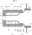
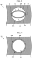
- the cross-sectional shape of the first connecting portion 43A gradually changes from an elliptical shape to a circular shape, from the insertion end portion 42 side to the suction pipe main body 41 side. More specifically, in the first connecting portion 43A, the length of the elliptical shape in the minor axis direction gradually increases from the insertion end portion 42 side toward the suction pipe main body 41 side to coincide with the dimension of the elliptical shape in the major axis direction. As illustrated in FIG. 4 , the outer peripheral surface (an extending portion outer peripheral surface 43b) of the extending portion 43B abuts the suction port inner peripheral surface 32 over the entire circumference.
- the second connecting portion 43C is connected to the other side of the extending portion 43B.
Landscapes
- Engineering & Computer Science (AREA)
- Mechanical Engineering (AREA)
- General Engineering & Computer Science (AREA)
- Applications Or Details Of Rotary Compressors (AREA)
Claims (6)
- Système de compresseur (100) comprenant :un vilebrequin (16) qui est configuré pour tourner autour d'une ligne axiale (O) ;une unité de mécanisme de compression (10A) qui comprend un rotor de piston (13A, 13B) qui est configuré pour tourner de manière excentrique avec la rotation du vilebrequin (16), et un cylindre (12A, 12B) ayant une chambre de compression (R1, R2) logeant le rotor de piston formé à l'intérieur de cette dernière ;un boîtier (11) qui loge le vilebrequin (16) et l'unité de mécanisme de compression (10A) et qui est configuré pour permettre à un réfrigérant haute pression généré par l'unité de mécanisme de compression (10A) de s'écouler à travers ce dernier ;un accumulateur (24) dans lequel le réfrigérant est stocké ; etun tuyau d'aspiration (26A, 26B) dans lequel une partie d'extrémité d'insertion (42, 242, 342), destinée à être insérée dans un orifice d'aspiration (23A, 23B, 323A) formé dans le cylindre, est formée au niveau d'une partie d'extrémité, et qui est configurée pour fournir le réfrigérant avant la compression de l'accumulateur (24) à la chambre de compression,dans lequel, entre une surface périphérique externe (42B) de la partie d'extrémité d'insertion et une surface périphérique interne (32) de l'orifice d'aspiration, une région de butée (A1) dans laquelle la surface périphérique externe de la partie d'extrémité d'insertion et la surface périphérique interne de l'orifice d'aspiration viennent en butée entre elles, et une région sans butée (A2) formant un espace entre la surface périphérique externe (42B) de la partie d'extrémité d'insertion et la surface périphérique interne (32) de l'orifice d'aspiration, sont formées, le système de compresseur étant caractérisé en ce que :l'orifice d'aspiration (23A, 23B, 323A) ou la partie d'extrémité d'insertion (42, 242, 342) a une section transversale circulaire, etlorsque l'orifice d'aspiration (23A, 23B, 323A) a une section transversale circulaire, la partie d'extrémité d'insertion (42, 242, 342) a une section transversale elliptique, un bord d'extrémité dans une direction d'axe majeur de l'ellipse formant la région de butée (A1), et un bord d'extrémité dans une direction d'axe mineur formant la région sans butée (A2), etlorsque la partie d'extrémité d'insertion (42, 242, 342) a une section transversale circulaire,l'orifice d'aspiration (24a) a une section transversale elliptique, un bord d'extrémité dans la direction d'axe mineur de l'ellipse formant la région de butée (A1) et un bord d'extrémité dans la direction d'axe mineur formant la région sans butée (A2).
- Système de compresseur (100) selon la revendication 1, dans lequel la région sans butée (A2) est formée au moins d'un côté dans une direction de ligne axiale dans laquelle la ligne axiale s'étend par rapport à la partie d'extrémité d'insertion (42, 242, 342).
- Système de compresseur (100) selon la revendication 2, dans lequel la région sans butée (A2) est formée des deux côtés dans la direction de ligne axiale par rapport à la partie d'extrémité d'insertion (42, 242, 342).
- Système de compresseur (100) selon l'une quelconque des revendications 1 à 3, dans lequel la région de butée (A1) est formée des deux côtés dans une direction horizontale, orthogonale à la direction de ligne axiale dans laquelle la ligne axiale s'étend par rapport à la partie d'extrémité d'insertion (42, 242, 342).
- Système de compresseur (100) selon l'une quelconque des revendications 1 à 4, dans lequel, dans la région de butée (A1), la partie d'extrémité d'insertion vient en butée contre la surface périphérique interne (32) de l'orifice d'aspiration dans un état élastiquement déformé.
- Système de compresseur (100) selon l'une quelconque des revendications 1 à 5, dans lequel le tuyau d'aspiration (26A, 26B) a en outre :un corps principal de tuyau d'aspiration (41) qui vient en butée contre la surface périphérique interne (32) de l'orifice d'aspiration sur toute la circonférence, etune partie de raccordement (43) qui raccorde le corps principal de tuyau d'aspiration (41) et la partie d'extrémité d'insertion (42, 242, 342), etune surface d'extrémité de tuyau d'aspiration (42A), qui est une surface d'extrémité de la partie d'extrémité d'insertion, vient en butée contre une surface inférieure d'orifice d'aspiration (31) faisant face à la surface d'extrémité de tuyau d'aspiration (42A) dans l'orifice d'aspiration (23A, 23B, 323A).
Applications Claiming Priority (1)
| Application Number | Priority Date | Filing Date | Title |
|---|---|---|---|
| JP2018074090A JP2019183720A (ja) | 2018-04-06 | 2018-04-06 | 圧縮機システム |
Publications (3)
| Publication Number | Publication Date |
|---|---|
| EP3550147A1 EP3550147A1 (fr) | 2019-10-09 |
| EP3550147C0 EP3550147C0 (fr) | 2023-07-05 |
| EP3550147B1 true EP3550147B1 (fr) | 2023-07-05 |
Family
ID=66092228
Family Applications (1)
| Application Number | Title | Priority Date | Filing Date |
|---|---|---|---|
| EP19167376.3A Active EP3550147B1 (fr) | 2018-04-06 | 2019-04-04 | Système de compresseur |
Country Status (2)
| Country | Link |
|---|---|
| EP (1) | EP3550147B1 (fr) |
| JP (1) | JP2019183720A (fr) |
Families Citing this family (3)
| Publication number | Priority date | Publication date | Assignee | Title |
|---|---|---|---|---|
| KR102750451B1 (ko) * | 2019-09-04 | 2025-01-07 | 삼성전자주식회사 | 로터리 압축기 및 이를 포함하는 가전기기 |
| CN111536044A (zh) * | 2020-05-20 | 2020-08-14 | 珠海凌达压缩机有限公司 | 压缩机进气组件、压缩机以及空调 |
| CN116771645A (zh) * | 2022-03-11 | 2023-09-19 | 上海海立电器有限公司 | 一种进气组件及压缩机 |
Family Cites Families (5)
| Publication number | Priority date | Publication date | Assignee | Title |
|---|---|---|---|---|
| US4639198A (en) * | 1984-11-13 | 1987-01-27 | Tecumseh Products Company | Suction tube seal for a rotary compressor |
| JPH05312152A (ja) * | 1992-05-12 | 1993-11-22 | Daikin Ind Ltd | 圧縮機における配管接続装置 |
| JP2004285993A (ja) * | 2003-03-25 | 2004-10-14 | Matsushita Electric Ind Co Ltd | 密閉型圧縮機 |
| JP6112489B2 (ja) * | 2011-11-08 | 2017-04-12 | パナソニックIpマネジメント株式会社 | 圧縮機 |
| JP6080646B2 (ja) | 2013-03-27 | 2017-02-15 | 三菱電機株式会社 | 回転圧縮機 |
-
2018
- 2018-04-06 JP JP2018074090A patent/JP2019183720A/ja active Pending
-
2019
- 2019-04-04 EP EP19167376.3A patent/EP3550147B1/fr active Active
Also Published As
| Publication number | Publication date |
|---|---|
| JP2019183720A (ja) | 2019-10-24 |
| EP3550147A1 (fr) | 2019-10-09 |
| EP3550147C0 (fr) | 2023-07-05 |
Similar Documents
| Publication | Publication Date | Title |
|---|---|---|
| CN104204531B (zh) | 气体压缩机 | |
| EP3550147B1 (fr) | Système de compresseur | |
| WO2013145713A1 (fr) | Compresseur | |
| KR20150083036A (ko) | 전동 압축기 | |
| US20100322796A1 (en) | Hermetic compressor | |
| JP2006009792A (ja) | 回転式圧縮機 | |
| KR101667710B1 (ko) | 로터리 압축기 | |
| US10533554B2 (en) | Cylinder-rotation compressor with improved vane and suction passage locations | |
| JP2010121481A (ja) | ロータリ圧縮機 | |
| CN113330218A (zh) | 涡旋式压缩机 | |
| US11136982B2 (en) | Screw compressor | |
| US10125770B2 (en) | Cylinder-rotation compressor with a discharge valve | |
| WO2015025449A1 (fr) | Compresseur multi-étagé et dispositif à cycle de réfrigération | |
| CN104819154A (zh) | 密闭型压缩机 | |
| JP2005146986A (ja) | アキュームレータ内蔵及び熱交換器一体型コンプレッサ | |
| EP3141754B1 (fr) | Compresseur rotatif et son procédé de fabrication | |
| EP3550146B1 (fr) | Système de compresseur | |
| JP2009167976A (ja) | 回転式流体機械 | |
| JP4948557B2 (ja) | 多段圧縮機および冷凍空調装置 | |
| JP7697492B2 (ja) | ロータリ圧縮機 | |
| JP2007113489A (ja) | 回転式圧縮機 | |
| JP6596787B2 (ja) | スクロール圧縮機 | |
| JP6374737B2 (ja) | シリンダ回転型圧縮機 | |
| CN111868384B (zh) | 多级压缩机 | |
| EP3557067B1 (fr) | Rotor à piston, vilebrequin, compresseur rotatif et procédé d'assemblage de vilebrequin |
Legal Events
| Date | Code | Title | Description |
|---|---|---|---|
| PUAI | Public reference made under article 153(3) epc to a published international application that has entered the european phase |
Free format text: ORIGINAL CODE: 0009012 |
|
| STAA | Information on the status of an ep patent application or granted ep patent |
Free format text: STATUS: THE APPLICATION HAS BEEN PUBLISHED |
|
| AK | Designated contracting states |
Kind code of ref document: A1 Designated state(s): AL AT BE BG CH CY CZ DE DK EE ES FI FR GB GR HR HU IE IS IT LI LT LU LV MC MK MT NL NO PL PT RO RS SE SI SK SM TR |
|
| AX | Request for extension of the european patent |
Extension state: BA ME |
|
| STAA | Information on the status of an ep patent application or granted ep patent |
Free format text: STATUS: REQUEST FOR EXAMINATION WAS MADE |
|
| 17P | Request for examination filed |
Effective date: 20200409 |
|
| RBV | Designated contracting states (corrected) |
Designated state(s): AL AT BE BG CH CY CZ DE DK EE ES FI FR GB GR HR HU IE IS IT LI LT LU LV MC MK MT NL NO PL PT RO RS SE SI SK SM TR |
|
| STAA | Information on the status of an ep patent application or granted ep patent |
Free format text: STATUS: EXAMINATION IS IN PROGRESS |
|
| 17Q | First examination report despatched |
Effective date: 20220307 |
|
| GRAP | Despatch of communication of intention to grant a patent |
Free format text: ORIGINAL CODE: EPIDOSNIGR1 |
|
| STAA | Information on the status of an ep patent application or granted ep patent |
Free format text: STATUS: GRANT OF PATENT IS INTENDED |
|
| INTG | Intention to grant announced |
Effective date: 20230120 |
|
| GRAS | Grant fee paid |
Free format text: ORIGINAL CODE: EPIDOSNIGR3 |
|
| GRAA | (expected) grant |
Free format text: ORIGINAL CODE: 0009210 |
|
| STAA | Information on the status of an ep patent application or granted ep patent |
Free format text: STATUS: THE PATENT HAS BEEN GRANTED |
|
| AK | Designated contracting states |
Kind code of ref document: B1 Designated state(s): AL AT BE BG CH CY CZ DE DK EE ES FI FR GB GR HR HU IE IS IT LI LT LU LV MC MK MT NL NO PL PT RO RS SE SI SK SM TR |
|
| REG | Reference to a national code |
Ref country code: CH Ref legal event code: EP |
|
| REG | Reference to a national code |
Ref country code: AT Ref legal event code: REF Ref document number: 1585080 Country of ref document: AT Kind code of ref document: T Effective date: 20230715 |
|
| REG | Reference to a national code |
Ref country code: DE Ref legal event code: R096 Ref document number: 602019031968 Country of ref document: DE |
|
| REG | Reference to a national code |
Ref country code: IE Ref legal event code: FG4D |
|
| U01 | Request for unitary effect filed |
Effective date: 20230705 |
|
| RAP4 | Party data changed (patent owner data changed or rights of a patent transferred) |
Owner name: MITSUBISHI HEAVY INDUSTRIES THERMAL SYSTEMS, LTD. |
|
| U07 | Unitary effect registered |
Designated state(s): AT BE BG DE DK EE FI FR IT LT LU LV MT NL PT SE SI Effective date: 20230728 |
|
| REG | Reference to a national code |
Ref country code: LT Ref legal event code: MG9D |
|
| PG25 | Lapsed in a contracting state [announced via postgrant information from national office to epo] |
Ref country code: GR Free format text: LAPSE BECAUSE OF FAILURE TO SUBMIT A TRANSLATION OF THE DESCRIPTION OR TO PAY THE FEE WITHIN THE PRESCRIBED TIME-LIMIT Effective date: 20231006 |
|
| PG25 | Lapsed in a contracting state [announced via postgrant information from national office to epo] |
Ref country code: ES Free format text: LAPSE BECAUSE OF FAILURE TO SUBMIT A TRANSLATION OF THE DESCRIPTION OR TO PAY THE FEE WITHIN THE PRESCRIBED TIME-LIMIT Effective date: 20230705 |
|
| PG25 | Lapsed in a contracting state [announced via postgrant information from national office to epo] |
Ref country code: IS Free format text: LAPSE BECAUSE OF FAILURE TO SUBMIT A TRANSLATION OF THE DESCRIPTION OR TO PAY THE FEE WITHIN THE PRESCRIBED TIME-LIMIT Effective date: 20231105 |
|
| PG25 | Lapsed in a contracting state [announced via postgrant information from national office to epo] |
Ref country code: RS Free format text: LAPSE BECAUSE OF FAILURE TO SUBMIT A TRANSLATION OF THE DESCRIPTION OR TO PAY THE FEE WITHIN THE PRESCRIBED TIME-LIMIT Effective date: 20230705 Ref country code: NO Free format text: LAPSE BECAUSE OF FAILURE TO SUBMIT A TRANSLATION OF THE DESCRIPTION OR TO PAY THE FEE WITHIN THE PRESCRIBED TIME-LIMIT Effective date: 20231005 Ref country code: IS Free format text: LAPSE BECAUSE OF FAILURE TO SUBMIT A TRANSLATION OF THE DESCRIPTION OR TO PAY THE FEE WITHIN THE PRESCRIBED TIME-LIMIT Effective date: 20231105 Ref country code: HR Free format text: LAPSE BECAUSE OF FAILURE TO SUBMIT A TRANSLATION OF THE DESCRIPTION OR TO PAY THE FEE WITHIN THE PRESCRIBED TIME-LIMIT Effective date: 20230705 Ref country code: GR Free format text: LAPSE BECAUSE OF FAILURE TO SUBMIT A TRANSLATION OF THE DESCRIPTION OR TO PAY THE FEE WITHIN THE PRESCRIBED TIME-LIMIT Effective date: 20231006 Ref country code: ES Free format text: LAPSE BECAUSE OF FAILURE TO SUBMIT A TRANSLATION OF THE DESCRIPTION OR TO PAY THE FEE WITHIN THE PRESCRIBED TIME-LIMIT Effective date: 20230705 |
|
| PG25 | Lapsed in a contracting state [announced via postgrant information from national office to epo] |
Ref country code: PL Free format text: LAPSE BECAUSE OF FAILURE TO SUBMIT A TRANSLATION OF THE DESCRIPTION OR TO PAY THE FEE WITHIN THE PRESCRIBED TIME-LIMIT Effective date: 20230705 |
|
| REG | Reference to a national code |
Ref country code: DE Ref legal event code: R097 Ref document number: 602019031968 Country of ref document: DE |
|
| U20 | Renewal fee for the european patent with unitary effect paid |
Year of fee payment: 6 Effective date: 20240306 |
|
| PG25 | Lapsed in a contracting state [announced via postgrant information from national office to epo] |
Ref country code: SM Free format text: LAPSE BECAUSE OF FAILURE TO SUBMIT A TRANSLATION OF THE DESCRIPTION OR TO PAY THE FEE WITHIN THE PRESCRIBED TIME-LIMIT Effective date: 20230705 Ref country code: RO Free format text: LAPSE BECAUSE OF FAILURE TO SUBMIT A TRANSLATION OF THE DESCRIPTION OR TO PAY THE FEE WITHIN THE PRESCRIBED TIME-LIMIT Effective date: 20230705 Ref country code: CZ Free format text: LAPSE BECAUSE OF FAILURE TO SUBMIT A TRANSLATION OF THE DESCRIPTION OR TO PAY THE FEE WITHIN THE PRESCRIBED TIME-LIMIT Effective date: 20230705 Ref country code: SK Free format text: LAPSE BECAUSE OF FAILURE TO SUBMIT A TRANSLATION OF THE DESCRIPTION OR TO PAY THE FEE WITHIN THE PRESCRIBED TIME-LIMIT Effective date: 20230705 |
|
| PLBE | No opposition filed within time limit |
Free format text: ORIGINAL CODE: 0009261 |
|
| STAA | Information on the status of an ep patent application or granted ep patent |
Free format text: STATUS: NO OPPOSITION FILED WITHIN TIME LIMIT |
|
| 26N | No opposition filed |
Effective date: 20240408 |
|
| PG25 | Lapsed in a contracting state [announced via postgrant information from national office to epo] |
Ref country code: MC Free format text: LAPSE BECAUSE OF FAILURE TO SUBMIT A TRANSLATION OF THE DESCRIPTION OR TO PAY THE FEE WITHIN THE PRESCRIBED TIME-LIMIT Effective date: 20230705 |
|
| PG25 | Lapsed in a contracting state [announced via postgrant information from national office to epo] |
Ref country code: MC Free format text: LAPSE BECAUSE OF FAILURE TO SUBMIT A TRANSLATION OF THE DESCRIPTION OR TO PAY THE FEE WITHIN THE PRESCRIBED TIME-LIMIT Effective date: 20230705 |
|
| REG | Reference to a national code |
Ref country code: CH Ref legal event code: PL |
|
| PG25 | Lapsed in a contracting state [announced via postgrant information from national office to epo] |
Ref country code: CH Free format text: LAPSE BECAUSE OF NON-PAYMENT OF DUE FEES Effective date: 20240430 |
|
| U20 | Renewal fee for the european patent with unitary effect paid |
Year of fee payment: 7 Effective date: 20250310 |
|
| PG25 | Lapsed in a contracting state [announced via postgrant information from national office to epo] |
Ref country code: IE Free format text: LAPSE BECAUSE OF NON-PAYMENT OF DUE FEES Effective date: 20240404 |
|
| PG25 | Lapsed in a contracting state [announced via postgrant information from national office to epo] |
Ref country code: CY Free format text: LAPSE BECAUSE OF FAILURE TO SUBMIT A TRANSLATION OF THE DESCRIPTION OR TO PAY THE FEE WITHIN THE PRESCRIBED TIME-LIMIT; INVALID AB INITIO Effective date: 20190404 |
|
| PG25 | Lapsed in a contracting state [announced via postgrant information from national office to epo] |
Ref country code: HU Free format text: LAPSE BECAUSE OF FAILURE TO SUBMIT A TRANSLATION OF THE DESCRIPTION OR TO PAY THE FEE WITHIN THE PRESCRIBED TIME-LIMIT; INVALID AB INITIO Effective date: 20190404 |
|
| PG25 | Lapsed in a contracting state [announced via postgrant information from national office to epo] |
Ref country code: TR Free format text: LAPSE BECAUSE OF FAILURE TO SUBMIT A TRANSLATION OF THE DESCRIPTION OR TO PAY THE FEE WITHIN THE PRESCRIBED TIME-LIMIT Effective date: 20230705 |
|
| PGFP | Annual fee paid to national office [announced via postgrant information from national office to epo] |
Ref country code: GB Payment date: 20260313 Year of fee payment: 8 |
|
| U20 | Renewal fee for the european patent with unitary effect paid |
Year of fee payment: 8 Effective date: 20260310 |