EP3550117B1 - Structure de récupération de chaleur d'échappement - Google Patents
Structure de récupération de chaleur d'échappement Download PDFInfo
- Publication number
- EP3550117B1 EP3550117B1 EP19164556.3A EP19164556A EP3550117B1 EP 3550117 B1 EP3550117 B1 EP 3550117B1 EP 19164556 A EP19164556 A EP 19164556A EP 3550117 B1 EP3550117 B1 EP 3550117B1
- Authority
- EP
- European Patent Office
- Prior art keywords
- pipe
- pipe body
- exhaust gas
- opening
- heat recovery
- Prior art date
- Legal status (The legal status is an assumption and is not a legal conclusion. Google has not performed a legal analysis and makes no representation as to the accuracy of the status listed.)
- Not-in-force
Links
Images


Classifications
-
- F—MECHANICAL ENGINEERING; LIGHTING; HEATING; WEAPONS; BLASTING
- F02—COMBUSTION ENGINES; HOT-GAS OR COMBUSTION-PRODUCT ENGINE PLANTS
- F02D—CONTROLLING COMBUSTION ENGINES
- F02D41/00—Electrical control of supply of combustible mixture or its constituents
- F02D41/02—Circuit arrangements for generating control signals
- F02D41/04—Introducing corrections for particular operating conditions
- F02D41/06—Introducing corrections for particular operating conditions for engine starting or warming up
- F02D41/068—Introducing corrections for particular operating conditions for engine starting or warming up for warming-up
-
- F—MECHANICAL ENGINEERING; LIGHTING; HEATING; WEAPONS; BLASTING
- F01—MACHINES OR ENGINES IN GENERAL; ENGINE PLANTS IN GENERAL; STEAM ENGINES
- F01N—GAS-FLOW SILENCERS OR EXHAUST APPARATUS FOR MACHINES OR ENGINES IN GENERAL; GAS-FLOW SILENCERS OR EXHAUST APPARATUS FOR INTERNAL-COMBUSTION ENGINES
- F01N3/00—Exhaust or silencing apparatus having means for purifying, rendering innocuous, or otherwise treating exhaust
- F01N3/02—Exhaust or silencing apparatus having means for purifying, rendering innocuous, or otherwise treating exhaust for cooling, or for removing solid constituents of, exhaust
- F01N3/0205—Exhaust or silencing apparatus having means for purifying, rendering innocuous, or otherwise treating exhaust for cooling, or for removing solid constituents of, exhaust using heat exchangers
-
- F—MECHANICAL ENGINEERING; LIGHTING; HEATING; WEAPONS; BLASTING
- F01—MACHINES OR ENGINES IN GENERAL; ENGINE PLANTS IN GENERAL; STEAM ENGINES
- F01N—GAS-FLOW SILENCERS OR EXHAUST APPARATUS FOR MACHINES OR ENGINES IN GENERAL; GAS-FLOW SILENCERS OR EXHAUST APPARATUS FOR INTERNAL-COMBUSTION ENGINES
- F01N3/00—Exhaust or silencing apparatus having means for purifying, rendering innocuous, or otherwise treating exhaust
- F01N3/08—Exhaust or silencing apparatus having means for purifying, rendering innocuous, or otherwise treating exhaust for rendering innocuous
- F01N3/10—Exhaust or silencing apparatus having means for purifying, rendering innocuous, or otherwise treating exhaust for rendering innocuous by thermal or catalytic conversion of noxious components of exhaust
- F01N3/24—Exhaust or silencing apparatus having means for purifying, rendering innocuous, or otherwise treating exhaust for rendering innocuous by thermal or catalytic conversion of noxious components of exhaust characterised by constructional aspects of converting apparatus
- F01N3/28—Construction of catalytic reactors
- F01N3/2882—Catalytic reactors combined or associated with other devices, e.g. exhaust silencers or other exhaust purification devices
- F01N3/2889—Catalytic reactors combined or associated with other devices, e.g. exhaust silencers or other exhaust purification devices with heat exchangers in a single housing
-
- F—MECHANICAL ENGINEERING; LIGHTING; HEATING; WEAPONS; BLASTING
- F01—MACHINES OR ENGINES IN GENERAL; ENGINE PLANTS IN GENERAL; STEAM ENGINES
- F01N—GAS-FLOW SILENCERS OR EXHAUST APPARATUS FOR MACHINES OR ENGINES IN GENERAL; GAS-FLOW SILENCERS OR EXHAUST APPARATUS FOR INTERNAL-COMBUSTION ENGINES
- F01N5/00—Exhaust or silencing apparatus combined or associated with devices profiting by exhaust energy
- F01N5/02—Exhaust or silencing apparatus combined or associated with devices profiting by exhaust energy the devices using heat
-
- F—MECHANICAL ENGINEERING; LIGHTING; HEATING; WEAPONS; BLASTING
- F02—COMBUSTION ENGINES; HOT-GAS OR COMBUSTION-PRODUCT ENGINE PLANTS
- F02N—STARTING OF COMBUSTION ENGINES; STARTING AIDS FOR SUCH ENGINES, NOT OTHERWISE PROVIDED FOR
- F02N19/00—Starting aids for combustion engines, not otherwise provided for
- F02N19/02—Aiding engine start by thermal means, e.g. using lighted wicks
- F02N19/04—Aiding engine start by thermal means, e.g. using lighted wicks by heating of fluids used in engines
- F02N19/10—Aiding engine start by thermal means, e.g. using lighted wicks by heating of fluids used in engines by heating of engine coolants
-
- F—MECHANICAL ENGINEERING; LIGHTING; HEATING; WEAPONS; BLASTING
- F01—MACHINES OR ENGINES IN GENERAL; ENGINE PLANTS IN GENERAL; STEAM ENGINES
- F01N—GAS-FLOW SILENCERS OR EXHAUST APPARATUS FOR MACHINES OR ENGINES IN GENERAL; GAS-FLOW SILENCERS OR EXHAUST APPARATUS FOR INTERNAL-COMBUSTION ENGINES
- F01N2240/00—Combination or association of two or more different exhaust treating devices, or of at least one such device with an auxiliary device, not covered by indexing codes F01N2230/00 or F01N2250/00, one of the devices being
- F01N2240/02—Combination or association of two or more different exhaust treating devices, or of at least one such device with an auxiliary device, not covered by indexing codes F01N2230/00 or F01N2250/00, one of the devices being a heat exchanger
-
- F—MECHANICAL ENGINEERING; LIGHTING; HEATING; WEAPONS; BLASTING
- F01—MACHINES OR ENGINES IN GENERAL; ENGINE PLANTS IN GENERAL; STEAM ENGINES
- F01N—GAS-FLOW SILENCERS OR EXHAUST APPARATUS FOR MACHINES OR ENGINES IN GENERAL; GAS-FLOW SILENCERS OR EXHAUST APPARATUS FOR INTERNAL-COMBUSTION ENGINES
- F01N2240/00—Combination or association of two or more different exhaust treating devices, or of at least one such device with an auxiliary device, not covered by indexing codes F01N2230/00 or F01N2250/00, one of the devices being
- F01N2240/36—Combination or association of two or more different exhaust treating devices, or of at least one such device with an auxiliary device, not covered by indexing codes F01N2230/00 or F01N2250/00, one of the devices being an exhaust flap
-
- F—MECHANICAL ENGINEERING; LIGHTING; HEATING; WEAPONS; BLASTING
- F01—MACHINES OR ENGINES IN GENERAL; ENGINE PLANTS IN GENERAL; STEAM ENGINES
- F01N—GAS-FLOW SILENCERS OR EXHAUST APPARATUS FOR MACHINES OR ENGINES IN GENERAL; GAS-FLOW SILENCERS OR EXHAUST APPARATUS FOR INTERNAL-COMBUSTION ENGINES
- F01N2390/00—Arrangements for controlling or regulating exhaust apparatus
-
- F—MECHANICAL ENGINEERING; LIGHTING; HEATING; WEAPONS; BLASTING
- F01—MACHINES OR ENGINES IN GENERAL; ENGINE PLANTS IN GENERAL; STEAM ENGINES
- F01N—GAS-FLOW SILENCERS OR EXHAUST APPARATUS FOR MACHINES OR ENGINES IN GENERAL; GAS-FLOW SILENCERS OR EXHAUST APPARATUS FOR INTERNAL-COMBUSTION ENGINES
- F01N2410/00—By-passing, at least partially, exhaust from inlet to outlet of apparatus, to atmosphere or to other device
- F01N2410/02—By-passing, at least partially, exhaust from inlet to outlet of apparatus, to atmosphere or to other device in case of high temperature, e.g. overheating of catalytic reactor
-
- Y—GENERAL TAGGING OF NEW TECHNOLOGICAL DEVELOPMENTS; GENERAL TAGGING OF CROSS-SECTIONAL TECHNOLOGIES SPANNING OVER SEVERAL SECTIONS OF THE IPC; TECHNICAL SUBJECTS COVERED BY FORMER USPC CROSS-REFERENCE ART COLLECTIONS [XRACs] AND DIGESTS
- Y02—TECHNOLOGIES OR APPLICATIONS FOR MITIGATION OR ADAPTATION AGAINST CLIMATE CHANGE
- Y02T—CLIMATE CHANGE MITIGATION TECHNOLOGIES RELATED TO TRANSPORTATION
- Y02T10/00—Road transport of goods or passengers
- Y02T10/10—Internal combustion engine [ICE] based vehicles
- Y02T10/12—Improving ICE efficiencies
Definitions
- the present disclosure relates to an exhaust heat recovery structure.
- JP-A Japanese Patent Application Laid-Open (JP-A) No. 2012-246836 discloses an exhaust heat recovery structure that exchanges heat between a first heat medium (exhaust gas) flowing through a heat-transfer tube and coolant flowing outside the heat-transfer tube.
- an exhaust gas channel is configured by two left and right components being welded along a flow direction of the exhaust gas. This structure must be welded in two places. Therefore, there is scope for improvement in regard to improving productivity.
- the present disclosure provides an exhaust heat recovery structure as defined in the claims that may improve productivity.
- a first aspect of the present disclosure is an exhaust heat recovery structure as defined in claim 1.
- the exhaust heat recovery structure relating to the first aspect includes the first pipe through which exhaust gas from the engine flows and the second pipe that branches from the first pipe.
- the heat exchanger that implements heat exchange from the exhaust gas is provided in the second pipe.
- the opening and closing valve is provided in the first pipe. Flow amounts of the exhaust gas flowing into the second pipe are adjusted by the opening and closing valve opening and closing. Therefore, in a case in which heat exchange is to be actively implemented, the opening and closing valve is fully closed and most of the exhaust gas flows into the second pipe. Conversely, when heat exchange is not required, the opening and closing valve is fully opened and most of the exhaust gas flows into the first pipe.
- the structure of the first pipe includes the first pipe body and the second pipe body that are adjacent in the flow direction of the exhaust gas.
- the join portion between the first pipe body and the second pipe body is provided along the circumferential direction of the first pipe. That is, the first pipe is formed by the first pipe body and the second pipe body being joined along the circumferential direction of the first pipe. Therefore, when, for example, the first pipe body and second pipe body are joined by welding, the first pipe may be formed with a single weld.
- the first pipe body is disposed at an upstream side of the flow direction of the exhaust gas, and the second pipe body may be disposed at the downstream side of the flow direction of the exhaust gas; and the first pipe body and second pipe body are joined in a state in which an end portion of the first pipe body, at a side thereof at which the second pipe body is disposed, may be superposed with an outer periphery face of the second pipe body.
- the joining is implemented in the state in which the end portion of the first pipe body that is disposed at the upstream side of the flow direction of the exhaust gas is superposed with the outer periphery face of the second pipe body. Therefore, in contrast with a structure in which the end portion of the first pipe body is superposed with an inner periphery face of the second pipe body, the join portion may be specified to be in a lower temperature region further to the exhaust gas downstream side.
- a connection hole at which a connecting pipe is connected may be formed at each of one axial direction end portion and another axial direction end portion of the first pipe; and, viewed in an axial direction of the first pipe, the connection hole may be formed in a circular shape with no irregularities.
- each connection hole is formed in a circular shape with no irregularities. Therefore, gaps between the connecting pipe and the first pipe are less likely to occur than in a structure in which a connection hole is formed in a non-continuous circular shape.
- the meaning of the term "a circular shape with no irregularities” as used herein is intended to exclude structures in which a portion of the periphery of a connection hole is formed in a protruding or recessed shape by a step or the like. Accordingly, the meaning of the term “a circular shape with no irregularities” is intended to include structures in which very small irregularities are formed during machining, as long as there are no protrusions or recesses in broad terms.
- productivity may be improved.
- thermal strain caused by exhaust gas acting on the join region may be suppressed.
- the arrow UP that is shown where appropriate in the drawings indicates a vehicle upper side
- the arrow FR indicates a vehicle front side.
- the directions front, rear, up, down, left and right are used without being particularly specified, the same represent the front and rear in the vehicle front-and-rear direction, up and down in the vehicle vertical direction, and left and right if facing in the forward progress direction.
- the exhaust heat recovery structure includes an exhaust heat recovery unit 10 that is disposed with an axial direction thereof in the front-and-rear direction of the vehicle.
- an engine (not shown in the drawings) is disposed at the vehicle front side relative to the exhaust heat recovery unit 10; exhaust gas flows from the engine.
- the vehicle front side is referred to as the exhaust gas flow upstream side and the vehicle rear side is referred to as the exhaust gas flow downstream side.
- the exhaust heat recovery unit 10 principally includes a first pipe 12, a second pipe 18, a heat exchanger 20 and an opening/closing valve 26. Below, overall structure of the exhaust heat recovery unit 10 is described and then the first pipe 12, which is a principal portion of the present structure, is described in detail.
- the first pipe 12 is a pipe body whose axial direction is in the vehicle front-and-rear direction.
- the first pipe 12 provides a channel along which the exhaust gas flows.
- a front side connection hole 12A is formed in an end portion at the vehicle front side (the exhaust gas flow upstream side) of the first pipe 12.
- the front side connection hole 12A is formed in a circular shape with no irregularities. That is, the periphery of the front side connection hole 12A is formed in a circular shape with no steps or the like.
- the front side connection hole 12A is structured such that a connecting pipe 22, which extends from the side of the first pipe 12 at which the engine is disposed, may be connected at the front side connection hole 12A.
- a rear side connection hole 12B is formed in an end portion at the vehicle rear side (the exhaust gas flow downstream side) of the first pipe 12. Similarly to the front side connection hole 12A, viewed in the axial direction of the first pipe 12, the rear side connection hole 12B is formed in a circular shape with no irregularities.
- a connecting pipe (not shown in the drawings) is connected at the rear side connection hole 12B. Exhaust gas that has passed through the exhaust heat recovery unit 10 flows through this connecting pipe toward a muffler (not shown in the drawings) at the downstream side.
- the second pipe 18 is disposed at the vehicle upper side of the first pipe 12.
- the second pipe 18 is a pipe body whose axial direction is in the vehicle front-and-rear direction.
- a front side connection hole 18A is formed in an end portion at the vehicle front side of the second pipe 18.
- One end portion of a front side water tube 21 is connected at the front side connection hole 18A.
- Another end side of the front side water tube 21 is connected to the engine. Accordingly, coolant that has passed through the engine passes through the front side water tube 21 and is introduced into the second pipe 18.
- a rear side connection hole 18B is formed in an end portion at the vehicle rear side of the second pipe 18.
- One end portion of a rear side water tube 23 is connected at the rear side connection hole 18B.
- Another end side of the rear side water tube 23 is connected to the engine. Accordingly, coolant that has passed through the second pipe 18 passes through the rear side water tube 23 and is fed back to the engine.
- a structure is formed such that the coolant is circulated between the engine and the second pipe 18.
- the heat exchanger 20 is provided at the second pipe 18.
- the heat exchanger 20 is an apparatus that implements heat exchange with the exhaust gas.
- Plural heat-transfer tubes (not shown in the drawings) are accommodated inside the heat exchanger 20, and fins are arranged inside the respective heat-transfer tubes.
- the exhaust gas flows inside the heat-transfer tubes.
- an inlet portion (not shown in the drawings) through which the exhaust gas is introduced is formed at a front end portion of the heat exchanger 20.
- Exhaust gas branching from the first pipe 12 into the second pipe 18 is introduced into the heat-transfer tubes of the heat exchanger 20 through the inlet portion.
- An outlet portion (not shown in the drawings) through which the exhaust gas flows out is formed at a rear end portion of the heat exchanger 20. The exhaust gas flowing out through the outlet portion flows from the second pipe 18 into the first pipe 12.
- a channel through which the coolant flows inside the second pipe 18 is formed outside the heat-transfer tubes. Consequently, heat is exchanged between the exhaust gas flowing inside the heat-transfer tubes and the coolant outside the heat-transfer tubes.
- the heat exchanger 20 is disposed on a support plate 24.
- the heat exchanger 20 is joined to the support plate 24 by welding or the like in a state in which peripheral edge portions of the support plate 24 are inflected toward the vehicle upper side and superposed with the first pipe 12.
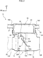
- the opening/closing valve 26 is provided in the first pipe 12. By opening and closing, the opening/closing valve 26 adjusts flow amounts of exhaust gas flowing into the second pipe 18. Viewed in the axial direction of the first pipe 12, the opening/closing valve 26 is formed in a substantially circular shape. In the fully closed state depicted in Fig. 1 , the opening/closing valve 26 is pressed against a stopper 28 that is disposed to encircle the opening/closing valve 26.
- the stopper 28 is formed in a substantially annular shape. Outer periphery edge portions of the stopper 28 are inflected toward the vehicle rear side and are joined to the first pipe 12 and the support plate 24.
- a mating portion 28A that is inflected toward the vehicle rear side and mates with the opening/closing valve 26 is formed at an inner periphery edge portion of the stopper 28.
- An abutting portion 26A is formed at an outer periphery edge portion of the opening/closing valve 26.
- the abutting portion 26A is inflected toward the vehicle rear side at an angle corresponding with the mating portion 28A of the stopper 28.
- a lower end portion 30A of an arm 30 is fixed to a face at the vehicle rear side of the opening/closing valve 26. In the fully closed state of the opening/closing valve 26, the arm 30 extends in the vehicle vertical direction.
- the lower end portion 30A of the arm 30 is fixed to a substantially central portion of the opening/closing valve 26.
- An upper end portion 30B of the arm 30 is fixed to a turning axle 32.
- the arm 30 is structured so as to swing in accordance with turning of the turning axle 32.
- an urging member (not shown in the drawings) is provided at the turning axle 32.
- the turning axle 32 is urged in the clockwise direction of the drawings by this urging member.
- the opening/closing valve 26 is pressed against the stopper 28.
- a resilient member is attached to at least one of the opening/closing valve 26 and the stopper 28.
- the turning axle 32 is connected to a driving mechanism (not shown in the drawings). When the driving mechanism operates, the turning axle 32 is turned.
- the driving mechanism is electronically connected to an electronic control unit (ECU), which is a control section.
- ECU electronice control unit
- the driving mechanism turns the turning axle 32 to predetermined angles, opening and closing the opening/closing valve 26, in accordance with signals from the ECU.
- the opening/closing valve 26 is put into the fully closed state in accordance with signals from the ECU. Therefore, exhaust gas flows into the heat exchanger 20 in the second pipe 18, and heat exchange between the coolant and the exhaust gas is actively implemented. Consequently, the coolant may be heated and the warmup may be accelerated. After the warmup, as shown in Fig.
- the turning axle 32 is turned to a predetermined angle in accordance with signals from the ECU, opening the opening/closing valve 26. Therefore, the first pipe 12 is opened up and amounts of exhaust gas flowing into the second pipe 18 are reduced. Consequently, heat exchange between the coolant and the exhaust gas may be suppressed, and a temperature rise of the coolant may be restrained.
- the first pipe 12 includes a first pipe body 14 and a second pipe body 16 that are adjacent in the flow direction of the exhaust gas.
- the first pipe body 14 is disposed at the vehicle front side (the exhaust gas flow direction upstream side).
- the front side connection hole 12A is formed in a front end portion of the first pipe body 14.
- a rear end portion 14A of the first pipe body 14 has a slightly larger diameter than a general portion of the first pipe body 14.
- the rear end portion 14A is superposed with an outer periphery face of the second pipe body 16, which is described below.
- the second pipe body 16 is disposed at the vehicle rear side (the exhaust gas flow direction downstream side) relative to the first pipe body 14.
- the rear side connection hole 12B is formed in a rear end portion of the second pipe body 16.
- an upper portion of the second pipe body 16 is open, and this opening portion is covered from the vehicle upper side thereof by the support plate 24.
- a front end portion 16A of the second pipe body 16 is superposed with an inner periphery face of the rear end portion 14A of the first pipe body 14.
- the first pipe body 14 and second pipe body 16 are welded (joined) in the region in which the rear end portion 14A of the first pipe body 14 and the front end portion 16A of the second pipe body 16 are superposed.
- a join portion between the first pipe body 14 and the second pipe body 16 is provided along the circumferential direction of the first pipe 12.
- the heat exchanger 20 is provided at the second pipe 18, and flow amounts of exhaust gas flowing into the second pipe 18 are adjusted by opening and closing of the opening/closing valve 26 provided at the first pipe 12. Therefore, when heat exchange is to be actively implemented, the opening/closing valve 26 is fully closed and most of the exhaust gas flows into the second pipe 18. Conversely, when heat exchange is not required, the opening/closing valve 26 is fully opened and most of the exhaust gas may flow into the first pipe 12.
- the first pipe 12 includes the first pipe body 14 and second pipe body 16 that are adjacent in the vehicle front-and-rear direction, and the join portion between the first pipe body 14 and the second pipe body 16 is provided along the circumferential direction of the first pipe 12. That is, the first pipe 12 is formed by the first pipe body 14 and second pipe body 16 being joined along the circumferential direction of the first pipe 12. Therefore, the first pipe 12 may be formed with a single weld, and productivity may be improved.
- the front side connection hole 12A and the rear side connection hole 12B are formed in circular shapes with no irregularities. That is, the periphery of the front side connection hole 12A and the periphery of the rear side connection hole 12B are free of protrusions and recesses formed by steps and the like. Therefore, the formation of a gap between the connecting pipe 22 and the first pipe 12 may be suppressed compared to a structure in which there is a protrusion or recess at a portion of the periphery of the connecting hole. Consequently, ease of assembly of the connecting pipe 22 may be improved.
- an exhaust heat recovery unit 100 includes a first pipe 102 and the second pipe 18.
- the second pipe 18 has the same structure as in the exemplary embodiment, and therefore is not described here.
- the first pipe 102 includes a first pipe body 104 and a second pipe body 106.
- the first pipe body 104 structures a lower half of the first pipe 102 and is formed in a substantially hemicylindrical shape extending in the vehicle front-and-rear direction. Therefore, an upper end portion 104A of the first pipe body 104 extends to the vehicle front and rear along a vertical direction middle portion of the first pipe 102.
- the second pipe body 106 structures the upper half of the first pipe 102 and extends in the vehicle front-and-rear direction. An opening portion in an upper portion of the second pipe body 106 is covered by the support plate 24 of the heat exchanger 20. A lower end portion 106A of the second pipe body 106 is superposed with an outer periphery face of the upper end portion 104A of the first pipe body 104.
- the first pipe body 104 and second pipe body 106 are welded (joined) in the region in which the upper end portion 104A of the first pipe body 104 and the lower end portion 106A of the second pipe body 106 are superposed. Thus, a join portion between the first pipe body 104 and the second pipe body 106 is provided along the axial direction of the first pipe 102.
- the vehicle left side has a similar structure. Therefore, in the comparative example, the first pipe body 104 and the second pipe body 106 are welded at two locations, at left and right.
- the first pipe 12 is formed by joining the first pipe body 14 to the second pipe body 16 along the circumferential direction of the first pipe 12, as shown in Fig. 1 . That is, if the first pipe body 14 and second pipe body 16 are joined by welding, the first pipe 12 may be formed with a single weld. Thus, productivity may be improved compared to the structure according to the comparative example.
- the front side connection hole 12A and the rear side connection hole 12B may be formed in single components. Therefore, the front side connection hole 12A and the rear side connection hole 12B may be formed in circular shapes with no irregularities, and ease of assembly of the connecting pipe 22 is improved. Furthermore, when a join portion is provided along the axial direction as in the comparative example, a temperature difference occurs between a front end and rear end of the join portion. In contrast, this temperature difference is unlikely to occur in the join portion according to the present exemplary embodiment. Therefore, thermal strain may be suppressed.
- the first pipe body 14 and second pipe body 16 are joined in the state in which the rear end portion 14A of the first pipe body 14 is superposed with the outer periphery face of the front end portion 16A of the second pipe body 16. Therefore, compared with a structure in which the rear end portion 14A of the first pipe body 14 is superposed with an inner periphery face of the second pipe body 16, the join portion between the two members may be specified to be further to the exhaust gas downstream side.
- the exhaust gas is at lower temperatures at the downstream side closer to the muffler than at the upstream side closer to the engine. Therefore, consequent to the effects of the structure of the present exemplary embodiment, the join portion between the first pipe body 14 and the second pipe body 16 may be specified to be in a lower temperature region, and thermal strain caused by exhaust gas acting on the join region may be suppressed.
- first pipe 12 When the first pipe 12 is structured by the first pipe body 14 and the second pipe body 16 that are adjacent in the vehicle front-and-rear direction as in the present exemplary embodiment, versatility may be improved.
- the diameter of the front side connection hole 12A when the diameter of the front side connection hole 12A is to be modified, such as when the structure is to be employed in a different model of vehicle or the like, it is sufficient to modify only the design of the first pipe body 14.
- the diameter of the rear side connection hole 12B when the diameter of the rear side connection hole 12B is to be modified, it is sufficient to modify only the design of the second pipe body 16.
- adaptations may be implemented by design modifications of single components.
- the second pipe 18 is disposed at the vehicle upper side of the first pipe 12, but this is not limiting. Structures are possible in which the second pipe 18 is disposed at the vehicle right side or vehicle left side of the first pipe 12.
- the heat exchanger 20 is a structure in which exhaust gas is introduced into the heat-transfer tubes and heat exchange is implemented between this exhaust gas and a coolant, but this is not limiting.
- a heat exchanger may be formed inside which coolant channels are provided instead of the heat-transfer tubes. In this case, heat is exchanged between the coolant flowing in the channels and exhaust gas outside the channels.
- the rear end portion 14A of the first pipe body 14 is superposed with the outer periphery face of the second pipe body 16, but this is not limiting. That is, structures are possible in which the front end portion 16A of the second pipe body 16 is superposed with an outer periphery face of the first pipe body 14 of the first pipe 12.
- the opening/closing valve 26 is disposed at the first pipe body 14 side of the first pipe 12.
- structures are possible in which the opening/closing valve 26 is disposed at the second pipe body 16 side.
- a structure for opening and closing the opening/closing valve 26 is not limited to the illustrated structure. Various structures may be employed, provided the opening/closing valve 26 may be opened and closed.
Landscapes
- Engineering & Computer Science (AREA)
- Chemical & Material Sciences (AREA)
- Combustion & Propulsion (AREA)
- Mechanical Engineering (AREA)
- General Engineering & Computer Science (AREA)
- Chemical Kinetics & Catalysis (AREA)
- Health & Medical Sciences (AREA)
- Toxicology (AREA)
- Exhaust Silencers (AREA)
Claims (4)
- Structure de récupération de chaleur d'échappement comprenant :un premier tuyau (12) à travers lequel du gaz d'échappement d'un moteur s'écoule;un deuxième tuyau (18) qui s'embranche depuis le premier tuyau (12), un échangeur de chaleur (20) configuré pour mettre en œuvre un échange de chaleur avec le gaz d'échappement qui est prévu au niveau du deuxième tuyau (18) ; etune soupape d'ouverture et de fermeture (26) prévue au niveau du premier tuyau (12), la soupape d'ouverture et de fermeture (26) étant configurée pour ajuster des quantités d'écoulement du gaz d'échappement qui s'écoulent dans le deuxième tuyau (18) en s'ouvrant et se fermant,le premier tuyau (12) comprenant un premier corps de tuyau (14) et un deuxième corps de tuyau (16) qui sont adjacents dans une direction d'écoulement du gaz d'échappement, et une partie de jonction entre le premier corps de tuyau (14) et le deuxième corps de tuyau (16) étant prévue le long d'une direction circonférentielle du premier tuyau (12),caractérisée en ce quela soupape d'ouverture et de fermeture (26) est disposée sur le côté de premier corps de tuyau (14) du premier tuyau (12),le premier corps de tuyau (14) est disposé sur un côté amont de la direction d'écoulement du gaz d'échappement, et le deuxième corps de tuyau (16) est disposé sur le côté aval de la direction d'écoulement du gaz d'échappement ; etle premier corps de tuyau (14) et le deuxième corps de tuyau (16) sont reliés dans un état dans lequel une partie d'extrémité du premier corps de tuyau (14), sur un côté de celui-ci au niveau duquel le deuxième corps de tuyau (16) est disposé, est superposée avec une face de périphérie extérieure du deuxième corps de tuyau (16).
- Structure de récupération de chaleur d'échappement selon la revendication 1, dans laquelle :un trou de raccordement (12A) au niveau duquel un tuyau de raccordement est raccordé est formé à chacune d'une partie d'extrémité de direction axiale et d'une autre partie d'extrémité de direction axiale du premier tuyau (12) ; et,vu dans une direction axiale du premier tuyau (12), le trou de raccordement (12A) est formé dans une forme circulaire sans irrégularité.
- Structure de récupération de chaleur d'échappement selon l'une quelconque des revendications 1 ou 2, configuré de telle sorte que de l'agent de refroidissement qui est passé à travers le moteur est introduit dans le deuxième tuyau (18).
- Structure de récupération de chaleur d'échappement selon la revendication 1, dans laquelle :une ouverture est prévue au niveau d'une partie supérieure du premier corps de tuyau (14) et du deuxième corps de tuyau (16) ; etl'ouverture est recouverte, depuis un côté supérieur de véhicule de celle-ci, par une plaque de support (24) qui supporte l'échangeur de chaleur (20).
Applications Claiming Priority (1)
| Application Number | Priority Date | Filing Date | Title |
|---|---|---|---|
| JP2018071625A JP2019183675A (ja) | 2018-04-03 | 2018-04-03 | 排熱回収器構造 |
Publications (2)
| Publication Number | Publication Date |
|---|---|
| EP3550117A1 EP3550117A1 (fr) | 2019-10-09 |
| EP3550117B1 true EP3550117B1 (fr) | 2021-09-08 |
Family
ID=65904302
Family Applications (1)
| Application Number | Title | Priority Date | Filing Date |
|---|---|---|---|
| EP19164556.3A Not-in-force EP3550117B1 (fr) | 2018-04-03 | 2019-03-22 | Structure de récupération de chaleur d'échappement |
Country Status (3)
| Country | Link |
|---|---|
| US (1) | US20190301386A1 (fr) |
| EP (1) | EP3550117B1 (fr) |
| JP (1) | JP2019183675A (fr) |
Family Cites Families (4)
| Publication number | Priority date | Publication date | Assignee | Title |
|---|---|---|---|---|
| JP2008038723A (ja) * | 2006-08-04 | 2008-02-21 | Toyota Motor Corp | 排気系熱交換器の支持構造 |
| JP5498988B2 (ja) | 2011-05-27 | 2014-05-21 | 株式会社ユタカ技研 | 熱回収器組立体及び排熱回収装置 |
| JP6245163B2 (ja) * | 2014-12-24 | 2017-12-13 | トヨタ自動車株式会社 | 排熱回収器構造 |
| CN106460625B (zh) * | 2015-03-04 | 2020-05-12 | 株式会社三五 | 热交换器及具有该热交换器的排气热回收装置 |
-
2018
- 2018-04-03 JP JP2018071625A patent/JP2019183675A/ja active Pending
-
2019
- 2019-03-22 EP EP19164556.3A patent/EP3550117B1/fr not_active Not-in-force
- 2019-03-22 US US16/361,916 patent/US20190301386A1/en not_active Abandoned
Also Published As
| Publication number | Publication date |
|---|---|
| JP2019183675A (ja) | 2019-10-24 |
| EP3550117A1 (fr) | 2019-10-09 |
| US20190301386A1 (en) | 2019-10-03 |
Similar Documents
| Publication | Publication Date | Title |
|---|---|---|
| US9273632B2 (en) | Heat exchanger for aircraft engine | |
| JP4878287B2 (ja) | 熱交換器 | |
| US10041389B2 (en) | Valve housing and valve | |
| EP3184764B1 (fr) | Structure de dérivation d'huile du refroidisseur d'huile | |
| EP2796685B1 (fr) | Dispositif de récupération de chaleur des gaz d'échappement | |
| JP7012566B2 (ja) | 制御バルブ | |
| US20080011456A1 (en) | Heat exchanger having integral elastic regions | |
| JP2005539171A (ja) | 多方向タービンシムシール | |
| EP3246609B1 (fr) | Tuyau caréné | |
| US11073073B2 (en) | Flow-path structure | |
| JP6010217B2 (ja) | 供給チャネルを有する熱交換器 | |
| EP3550117B1 (fr) | Structure de récupération de chaleur d'échappement | |
| JP2006046846A (ja) | 2重管式熱交換器 | |
| KR102323398B1 (ko) | 열교환기의 입출구파이프 용접구조 | |
| US20190178422A1 (en) | Fluid supply conduit and method for providing such a conduit | |
| CN103016212A (zh) | 废气热交换装置 | |
| CN113167165A (zh) | 排气热量回收系统 | |
| JP6353769B2 (ja) | タービンハウジング | |
| JP2001124248A (ja) | 金属パイプ | |
| US10605207B2 (en) | Exhaust heat recovery device | |
| EP3146177B1 (fr) | Moteur à combustion interne | |
| JP5842598B2 (ja) | 熱交換器 | |
| JP2023505223A5 (fr) | ||
| US12460817B2 (en) | Assembly, method for manufacturing assembly, burner, and method for manufacturing burner | |
| EP4506544A1 (fr) | Bague de diamètre extérieur avant thermiquement conforme pour moteur à turbine à gaz |
Legal Events
| Date | Code | Title | Description |
|---|---|---|---|
| PUAI | Public reference made under article 153(3) epc to a published international application that has entered the european phase |
Free format text: ORIGINAL CODE: 0009012 |
|
| STAA | Information on the status of an ep patent application or granted ep patent |
Free format text: STATUS: REQUEST FOR EXAMINATION WAS MADE |
|
| 17P | Request for examination filed |
Effective date: 20190322 |
|
| AK | Designated contracting states |
Kind code of ref document: A1 Designated state(s): AL AT BE BG CH CY CZ DE DK EE ES FI FR GB GR HR HU IE IS IT LI LT LU LV MC MK MT NL NO PL PT RO RS SE SI SK SM TR |
|
| AX | Request for extension of the european patent |
Extension state: BA ME |
|
| STAA | Information on the status of an ep patent application or granted ep patent |
Free format text: STATUS: EXAMINATION IS IN PROGRESS |
|
| 17Q | First examination report despatched |
Effective date: 20200225 |
|
| GRAP | Despatch of communication of intention to grant a patent |
Free format text: ORIGINAL CODE: EPIDOSNIGR1 |
|
| STAA | Information on the status of an ep patent application or granted ep patent |
Free format text: STATUS: GRANT OF PATENT IS INTENDED |
|
| INTG | Intention to grant announced |
Effective date: 20210406 |
|
| GRAS | Grant fee paid |
Free format text: ORIGINAL CODE: EPIDOSNIGR3 |
|
| GRAA | (expected) grant |
Free format text: ORIGINAL CODE: 0009210 |
|
| STAA | Information on the status of an ep patent application or granted ep patent |
Free format text: STATUS: THE PATENT HAS BEEN GRANTED |
|
| AK | Designated contracting states |
Kind code of ref document: B1 Designated state(s): AL AT BE BG CH CY CZ DE DK EE ES FI FR GB GR HR HU IE IS IT LI LT LU LV MC MK MT NL NO PL PT RO RS SE SI SK SM TR |
|
| REG | Reference to a national code |
Ref country code: GB Ref legal event code: FG4D |
|
| REG | Reference to a national code |
Ref country code: CH Ref legal event code: EP Ref country code: AT Ref legal event code: REF Ref document number: 1428790 Country of ref document: AT Kind code of ref document: T Effective date: 20210915 |
|
| REG | Reference to a national code |
Ref country code: DE Ref legal event code: R096 Ref document number: 602019007433 Country of ref document: DE |
|
| REG | Reference to a national code |
Ref country code: IE Ref legal event code: FG4D |
|
| REG | Reference to a national code |
Ref country code: LT Ref legal event code: MG9D |
|
| REG | Reference to a national code |
Ref country code: NL Ref legal event code: MP Effective date: 20210908 |
|
| PG25 | Lapsed in a contracting state [announced via postgrant information from national office to epo] |
Ref country code: LT Free format text: LAPSE BECAUSE OF FAILURE TO SUBMIT A TRANSLATION OF THE DESCRIPTION OR TO PAY THE FEE WITHIN THE PRESCRIBED TIME-LIMIT Effective date: 20210908 Ref country code: BG Free format text: LAPSE BECAUSE OF FAILURE TO SUBMIT A TRANSLATION OF THE DESCRIPTION OR TO PAY THE FEE WITHIN THE PRESCRIBED TIME-LIMIT Effective date: 20211208 Ref country code: HR Free format text: LAPSE BECAUSE OF FAILURE TO SUBMIT A TRANSLATION OF THE DESCRIPTION OR TO PAY THE FEE WITHIN THE PRESCRIBED TIME-LIMIT Effective date: 20210908 Ref country code: NO Free format text: LAPSE BECAUSE OF FAILURE TO SUBMIT A TRANSLATION OF THE DESCRIPTION OR TO PAY THE FEE WITHIN THE PRESCRIBED TIME-LIMIT Effective date: 20211208 Ref country code: FI Free format text: LAPSE BECAUSE OF FAILURE TO SUBMIT A TRANSLATION OF THE DESCRIPTION OR TO PAY THE FEE WITHIN THE PRESCRIBED TIME-LIMIT Effective date: 20210908 Ref country code: ES Free format text: LAPSE BECAUSE OF FAILURE TO SUBMIT A TRANSLATION OF THE DESCRIPTION OR TO PAY THE FEE WITHIN THE PRESCRIBED TIME-LIMIT Effective date: 20210908 Ref country code: RS Free format text: LAPSE BECAUSE OF FAILURE TO SUBMIT A TRANSLATION OF THE DESCRIPTION OR TO PAY THE FEE WITHIN THE PRESCRIBED TIME-LIMIT Effective date: 20210908 Ref country code: SE Free format text: LAPSE BECAUSE OF FAILURE TO SUBMIT A TRANSLATION OF THE DESCRIPTION OR TO PAY THE FEE WITHIN THE PRESCRIBED TIME-LIMIT Effective date: 20210908 |
|
| REG | Reference to a national code |
Ref country code: AT Ref legal event code: MK05 Ref document number: 1428790 Country of ref document: AT Kind code of ref document: T Effective date: 20210908 |
|
| PG25 | Lapsed in a contracting state [announced via postgrant information from national office to epo] |
Ref country code: LV Free format text: LAPSE BECAUSE OF FAILURE TO SUBMIT A TRANSLATION OF THE DESCRIPTION OR TO PAY THE FEE WITHIN THE PRESCRIBED TIME-LIMIT Effective date: 20210908 Ref country code: GR Free format text: LAPSE BECAUSE OF FAILURE TO SUBMIT A TRANSLATION OF THE DESCRIPTION OR TO PAY THE FEE WITHIN THE PRESCRIBED TIME-LIMIT Effective date: 20211209 |
|
| PG25 | Lapsed in a contracting state [announced via postgrant information from national office to epo] |
Ref country code: AT Free format text: LAPSE BECAUSE OF FAILURE TO SUBMIT A TRANSLATION OF THE DESCRIPTION OR TO PAY THE FEE WITHIN THE PRESCRIBED TIME-LIMIT Effective date: 20210908 |
|
| PGFP | Annual fee paid to national office [announced via postgrant information from national office to epo] |
Ref country code: DE Payment date: 20220203 Year of fee payment: 4 |
|
| PG25 | Lapsed in a contracting state [announced via postgrant information from national office to epo] |
Ref country code: IS Free format text: LAPSE BECAUSE OF FAILURE TO SUBMIT A TRANSLATION OF THE DESCRIPTION OR TO PAY THE FEE WITHIN THE PRESCRIBED TIME-LIMIT Effective date: 20220108 Ref country code: SM Free format text: LAPSE BECAUSE OF FAILURE TO SUBMIT A TRANSLATION OF THE DESCRIPTION OR TO PAY THE FEE WITHIN THE PRESCRIBED TIME-LIMIT Effective date: 20210908 Ref country code: SK Free format text: LAPSE BECAUSE OF FAILURE TO SUBMIT A TRANSLATION OF THE DESCRIPTION OR TO PAY THE FEE WITHIN THE PRESCRIBED TIME-LIMIT Effective date: 20210908 Ref country code: RO Free format text: LAPSE BECAUSE OF FAILURE TO SUBMIT A TRANSLATION OF THE DESCRIPTION OR TO PAY THE FEE WITHIN THE PRESCRIBED TIME-LIMIT Effective date: 20210908 Ref country code: PT Free format text: LAPSE BECAUSE OF FAILURE TO SUBMIT A TRANSLATION OF THE DESCRIPTION OR TO PAY THE FEE WITHIN THE PRESCRIBED TIME-LIMIT Effective date: 20220110 Ref country code: PL Free format text: LAPSE BECAUSE OF FAILURE TO SUBMIT A TRANSLATION OF THE DESCRIPTION OR TO PAY THE FEE WITHIN THE PRESCRIBED TIME-LIMIT Effective date: 20210908 Ref country code: NL Free format text: LAPSE BECAUSE OF FAILURE TO SUBMIT A TRANSLATION OF THE DESCRIPTION OR TO PAY THE FEE WITHIN THE PRESCRIBED TIME-LIMIT Effective date: 20210908 Ref country code: EE Free format text: LAPSE BECAUSE OF FAILURE TO SUBMIT A TRANSLATION OF THE DESCRIPTION OR TO PAY THE FEE WITHIN THE PRESCRIBED TIME-LIMIT Effective date: 20210908 Ref country code: CZ Free format text: LAPSE BECAUSE OF FAILURE TO SUBMIT A TRANSLATION OF THE DESCRIPTION OR TO PAY THE FEE WITHIN THE PRESCRIBED TIME-LIMIT Effective date: 20210908 Ref country code: AL Free format text: LAPSE BECAUSE OF FAILURE TO SUBMIT A TRANSLATION OF THE DESCRIPTION OR TO PAY THE FEE WITHIN THE PRESCRIBED TIME-LIMIT Effective date: 20210908 |
|
| PGFP | Annual fee paid to national office [announced via postgrant information from national office to epo] |
Ref country code: FR Payment date: 20220209 Year of fee payment: 4 |
|
| REG | Reference to a national code |
Ref country code: DE Ref legal event code: R097 Ref document number: 602019007433 Country of ref document: DE |
|
| PLBE | No opposition filed within time limit |
Free format text: ORIGINAL CODE: 0009261 |
|
| STAA | Information on the status of an ep patent application or granted ep patent |
Free format text: STATUS: NO OPPOSITION FILED WITHIN TIME LIMIT |
|
| PG25 | Lapsed in a contracting state [announced via postgrant information from national office to epo] |
Ref country code: DK Free format text: LAPSE BECAUSE OF FAILURE TO SUBMIT A TRANSLATION OF THE DESCRIPTION OR TO PAY THE FEE WITHIN THE PRESCRIBED TIME-LIMIT Effective date: 20210908 |
|
| 26N | No opposition filed |
Effective date: 20220609 |
|
| PG25 | Lapsed in a contracting state [announced via postgrant information from national office to epo] |
Ref country code: SI Free format text: LAPSE BECAUSE OF FAILURE TO SUBMIT A TRANSLATION OF THE DESCRIPTION OR TO PAY THE FEE WITHIN THE PRESCRIBED TIME-LIMIT Effective date: 20210908 |
|
| PG25 | Lapsed in a contracting state [announced via postgrant information from national office to epo] |
Ref country code: MC Free format text: LAPSE BECAUSE OF FAILURE TO SUBMIT A TRANSLATION OF THE DESCRIPTION OR TO PAY THE FEE WITHIN THE PRESCRIBED TIME-LIMIT Effective date: 20210908 |
|
| REG | Reference to a national code |
Ref country code: CH Ref legal event code: PL |
|
| REG | Reference to a national code |
Ref country code: BE Ref legal event code: MM Effective date: 20220331 |
|
| PG25 | Lapsed in a contracting state [announced via postgrant information from national office to epo] |
Ref country code: LU Free format text: LAPSE BECAUSE OF NON-PAYMENT OF DUE FEES Effective date: 20220322 Ref country code: LI Free format text: LAPSE BECAUSE OF NON-PAYMENT OF DUE FEES Effective date: 20220331 Ref country code: IT Free format text: LAPSE BECAUSE OF FAILURE TO SUBMIT A TRANSLATION OF THE DESCRIPTION OR TO PAY THE FEE WITHIN THE PRESCRIBED TIME-LIMIT Effective date: 20210908 Ref country code: IE Free format text: LAPSE BECAUSE OF NON-PAYMENT OF DUE FEES Effective date: 20220322 Ref country code: CH Free format text: LAPSE BECAUSE OF NON-PAYMENT OF DUE FEES Effective date: 20220331 |
|
| PG25 | Lapsed in a contracting state [announced via postgrant information from national office to epo] |
Ref country code: BE Free format text: LAPSE BECAUSE OF NON-PAYMENT OF DUE FEES Effective date: 20220331 |
|
| P01 | Opt-out of the competence of the unified patent court (upc) registered |
Effective date: 20230427 |
|
| REG | Reference to a national code |
Ref country code: DE Ref legal event code: R119 Ref document number: 602019007433 Country of ref document: DE |
|
| GBPC | Gb: european patent ceased through non-payment of renewal fee |
Effective date: 20230322 |
|
| PG25 | Lapsed in a contracting state [announced via postgrant information from national office to epo] |
Ref country code: GB Free format text: LAPSE BECAUSE OF NON-PAYMENT OF DUE FEES Effective date: 20230322 |
|
| PG25 | Lapsed in a contracting state [announced via postgrant information from national office to epo] |
Ref country code: GB Free format text: LAPSE BECAUSE OF NON-PAYMENT OF DUE FEES Effective date: 20230322 Ref country code: FR Free format text: LAPSE BECAUSE OF NON-PAYMENT OF DUE FEES Effective date: 20230331 Ref country code: DE Free format text: LAPSE BECAUSE OF NON-PAYMENT OF DUE FEES Effective date: 20231003 |
|
| PG25 | Lapsed in a contracting state [announced via postgrant information from national office to epo] |
Ref country code: MK Free format text: LAPSE BECAUSE OF FAILURE TO SUBMIT A TRANSLATION OF THE DESCRIPTION OR TO PAY THE FEE WITHIN THE PRESCRIBED TIME-LIMIT Effective date: 20210908 Ref country code: CY Free format text: LAPSE BECAUSE OF FAILURE TO SUBMIT A TRANSLATION OF THE DESCRIPTION OR TO PAY THE FEE WITHIN THE PRESCRIBED TIME-LIMIT Effective date: 20210908 |
|
| PG25 | Lapsed in a contracting state [announced via postgrant information from national office to epo] |
Ref country code: HU Free format text: LAPSE BECAUSE OF FAILURE TO SUBMIT A TRANSLATION OF THE DESCRIPTION OR TO PAY THE FEE WITHIN THE PRESCRIBED TIME-LIMIT; INVALID AB INITIO Effective date: 20190322 |
|
| PG25 | Lapsed in a contracting state [announced via postgrant information from national office to epo] |
Ref country code: MT Free format text: LAPSE BECAUSE OF FAILURE TO SUBMIT A TRANSLATION OF THE DESCRIPTION OR TO PAY THE FEE WITHIN THE PRESCRIBED TIME-LIMIT Effective date: 20210908 |
|
| PG25 | Lapsed in a contracting state [announced via postgrant information from national office to epo] |
Ref country code: TR Free format text: LAPSE BECAUSE OF FAILURE TO SUBMIT A TRANSLATION OF THE DESCRIPTION OR TO PAY THE FEE WITHIN THE PRESCRIBED TIME-LIMIT Effective date: 20210908 |