EP3549996A1 - Olefine durch fischer-tropsch-synthese - Google Patents
Olefine durch fischer-tropsch-synthese Download PDFInfo
- Publication number
- EP3549996A1 EP3549996A1 EP18165489.8A EP18165489A EP3549996A1 EP 3549996 A1 EP3549996 A1 EP 3549996A1 EP 18165489 A EP18165489 A EP 18165489A EP 3549996 A1 EP3549996 A1 EP 3549996A1
- Authority
- EP
- European Patent Office
- Prior art keywords
- catalyst
- fischer
- hydroformylation
- synthesis
- tropsch
- Prior art date
- Legal status (The legal status is an assumption and is not a legal conclusion. Google has not performed a legal analysis and makes no representation as to the accuracy of the status listed.)
- Ceased
Links
- 230000015572 biosynthetic process Effects 0.000 title claims abstract description 34
- 238000003786 synthesis reaction Methods 0.000 title claims abstract description 34
- 150000001336 alkenes Chemical class 0.000 title description 15
- 239000003054 catalyst Substances 0.000 claims abstract description 70
- 238000000034 method Methods 0.000 claims abstract description 35
- 229930195733 hydrocarbon Natural products 0.000 claims abstract description 15
- 229910052748 manganese Inorganic materials 0.000 claims abstract description 15
- 150000002430 hydrocarbons Chemical class 0.000 claims abstract description 14
- 239000007789 gas Substances 0.000 claims description 24
- 238000007037 hydroformylation reaction Methods 0.000 claims description 24
- 229910052739 hydrogen Inorganic materials 0.000 claims description 9
- UGFAIRIUMAVXCW-UHFFFAOYSA-N Carbon monoxide Chemical compound [O+]#[C-] UGFAIRIUMAVXCW-UHFFFAOYSA-N 0.000 claims description 8
- 229910002091 carbon monoxide Inorganic materials 0.000 claims description 8
- VYPSYNLAJGMNEJ-UHFFFAOYSA-N Silicium dioxide Chemical compound O=[Si]=O VYPSYNLAJGMNEJ-UHFFFAOYSA-N 0.000 claims description 7
- UFHFLCQGNIYNRP-UHFFFAOYSA-N Hydrogen Chemical compound [H][H] UFHFLCQGNIYNRP-UHFFFAOYSA-N 0.000 claims description 6
- 239000001257 hydrogen Substances 0.000 claims description 6
- 229910052751 metal Inorganic materials 0.000 claims description 6
- 239000002184 metal Substances 0.000 claims description 6
- 238000002360 preparation method Methods 0.000 claims description 4
- 238000000746 purification Methods 0.000 claims description 3
- 239000000377 silicon dioxide Substances 0.000 claims description 3
- 150000002739 metals Chemical class 0.000 claims description 2
- 239000000047 product Substances 0.000 description 24
- 238000006243 chemical reaction Methods 0.000 description 12
- VNWKTOKETHGBQD-UHFFFAOYSA-N methane Chemical compound C VNWKTOKETHGBQD-UHFFFAOYSA-N 0.000 description 12
- XEEYBQQBJWHFJM-UHFFFAOYSA-N Iron Chemical compound [Fe] XEEYBQQBJWHFJM-UHFFFAOYSA-N 0.000 description 11
- 229910017052 cobalt Inorganic materials 0.000 description 10
- 239000010941 cobalt Substances 0.000 description 10
- 239000000203 mixture Substances 0.000 description 10
- GUTLYIVDDKVIGB-UHFFFAOYSA-N cobalt atom Chemical compound [Co] GUTLYIVDDKVIGB-UHFFFAOYSA-N 0.000 description 9
- 238000009826 distribution Methods 0.000 description 8
- 239000003446 ligand Substances 0.000 description 7
- 230000004913 activation Effects 0.000 description 6
- 229910052799 carbon Inorganic materials 0.000 description 6
- 150000001868 cobalt Chemical class 0.000 description 6
- 229910052703 rhodium Inorganic materials 0.000 description 6
- 239000010948 rhodium Substances 0.000 description 6
- MHOVAHRLVXNVSD-UHFFFAOYSA-N rhodium atom Chemical compound [Rh] MHOVAHRLVXNVSD-UHFFFAOYSA-N 0.000 description 6
- 239000008346 aqueous phase Substances 0.000 description 5
- -1 for example Chemical class 0.000 description 5
- 229910052742 iron Inorganic materials 0.000 description 5
- JRZJOMJEPLMPRA-UHFFFAOYSA-N olefin Natural products CCCCCCCC=C JRZJOMJEPLMPRA-UHFFFAOYSA-N 0.000 description 5
- 239000012071 phase Substances 0.000 description 5
- OKTJSMMVPCPJKN-UHFFFAOYSA-N Carbon Chemical compound [C] OKTJSMMVPCPJKN-UHFFFAOYSA-N 0.000 description 4
- QQONPFPTGQHPMA-UHFFFAOYSA-N Propene Chemical compound CC=C QQONPFPTGQHPMA-UHFFFAOYSA-N 0.000 description 4
- 239000000470 constituent Substances 0.000 description 4
- 239000007788 liquid Substances 0.000 description 4
- BDAGIHXWWSANSR-UHFFFAOYSA-N methanoic acid Natural products OC=O BDAGIHXWWSANSR-UHFFFAOYSA-N 0.000 description 4
- 239000011541 reaction mixture Substances 0.000 description 4
- 239000012266 salt solution Substances 0.000 description 4
- 239000000243 solution Substances 0.000 description 4
- 150000001412 amines Chemical class 0.000 description 3
- 239000007864 aqueous solution Substances 0.000 description 3
- 239000001273 butane Substances 0.000 description 3
- 150000001875 compounds Chemical class 0.000 description 3
- 238000011068 loading method Methods 0.000 description 3
- IJDNQMDRQITEOD-UHFFFAOYSA-N n-butane Chemical compound CCCC IJDNQMDRQITEOD-UHFFFAOYSA-N 0.000 description 3
- OFBQJSOFQDEBGM-UHFFFAOYSA-N n-pentane Natural products CCCCC OFBQJSOFQDEBGM-UHFFFAOYSA-N 0.000 description 3
- 239000007858 starting material Substances 0.000 description 3
- XLYOFNOQVPJJNP-UHFFFAOYSA-N water Substances O XLYOFNOQVPJJNP-UHFFFAOYSA-N 0.000 description 3
- GVQAJJUPWDZQGD-UHFFFAOYSA-N 1-tert-butyl-3-(3-tert-butyl-5-methoxyphenyl)-5-methoxybenzene Chemical compound CC(C)(C)C1=CC(OC)=CC(C=2C=C(C=C(OC)C=2)C(C)(C)C)=C1 GVQAJJUPWDZQGD-UHFFFAOYSA-N 0.000 description 2
- OSWFIVFLDKOXQC-UHFFFAOYSA-N 4-(3-methoxyphenyl)aniline Chemical compound COC1=CC=CC(C=2C=CC(N)=CC=2)=C1 OSWFIVFLDKOXQC-UHFFFAOYSA-N 0.000 description 2
- 239000004215 Carbon black (E152) Substances 0.000 description 2
- OTMSDBZUPAUEDD-UHFFFAOYSA-N Ethane Chemical compound CC OTMSDBZUPAUEDD-UHFFFAOYSA-N 0.000 description 2
- VGGSQFUCUMXWEO-UHFFFAOYSA-N Ethene Chemical compound C=C VGGSQFUCUMXWEO-UHFFFAOYSA-N 0.000 description 2
- 229910002651 NO3 Inorganic materials 0.000 description 2
- ATUOYWHBWRKTHZ-UHFFFAOYSA-N Propane Chemical compound CCC ATUOYWHBWRKTHZ-UHFFFAOYSA-N 0.000 description 2
- 229910004298 SiO 2 Inorganic materials 0.000 description 2
- 150000001298 alcohols Chemical class 0.000 description 2
- 150000001299 aldehydes Chemical class 0.000 description 2
- 150000001335 aliphatic alkanes Chemical class 0.000 description 2
- 229910052782 aluminium Inorganic materials 0.000 description 2
- XAGFODPZIPBFFR-UHFFFAOYSA-N aluminium Chemical compound [Al] XAGFODPZIPBFFR-UHFFFAOYSA-N 0.000 description 2
- 238000004821 distillation Methods 0.000 description 2
- 238000002474 experimental method Methods 0.000 description 2
- 238000000605 extraction Methods 0.000 description 2
- 235000019253 formic acid Nutrition 0.000 description 2
- 238000010438 heat treatment Methods 0.000 description 2
- 238000002156 mixing Methods 0.000 description 2
- 239000003345 natural gas Substances 0.000 description 2
- 239000012074 organic phase Substances 0.000 description 2
- 150000002903 organophosphorus compounds Chemical class 0.000 description 2
- 230000003647 oxidation Effects 0.000 description 2
- 238000007254 oxidation reaction Methods 0.000 description 2
- OJMIONKXNSYLSR-UHFFFAOYSA-N phosphorous acid Chemical compound OP(O)O OJMIONKXNSYLSR-UHFFFAOYSA-N 0.000 description 2
- 150000003839 salts Chemical class 0.000 description 2
- 238000000926 separation method Methods 0.000 description 2
- 229910052814 silicon oxide Inorganic materials 0.000 description 2
- 125000000383 tetramethylene group Chemical group [H]C([H])([*:1])C([H])([H])C([H])([H])C([H])([H])[*:2] 0.000 description 2
- 238000010626 work up procedure Methods 0.000 description 2
- RKMGAJGJIURJSJ-UHFFFAOYSA-N 2,2,6,6-tetramethylpiperidine Chemical group CC1(C)CCCC(C)(C)N1 RKMGAJGJIURJSJ-UHFFFAOYSA-N 0.000 description 1
- LVZWSLJZHVFIQJ-UHFFFAOYSA-N Cyclopropane Chemical compound C1CC1 LVZWSLJZHVFIQJ-UHFFFAOYSA-N 0.000 description 1
- RTAQQCXQSZGOHL-UHFFFAOYSA-N Titanium Chemical compound [Ti] RTAQQCXQSZGOHL-UHFFFAOYSA-N 0.000 description 1
- 238000005299 abrasion Methods 0.000 description 1
- 239000000654 additive Substances 0.000 description 1
- PNEYBMLMFCGWSK-UHFFFAOYSA-N aluminium oxide Inorganic materials [O-2].[O-2].[O-2].[Al+3].[Al+3] PNEYBMLMFCGWSK-UHFFFAOYSA-N 0.000 description 1
- 239000011260 aqueous acid Substances 0.000 description 1
- 125000004429 atom Chemical group 0.000 description 1
- 238000009835 boiling Methods 0.000 description 1
- 239000006227 byproduct Substances 0.000 description 1
- 238000001354 calcination Methods 0.000 description 1
- 125000004432 carbon atom Chemical group C* 0.000 description 1
- 150000001735 carboxylic acids Chemical class 0.000 description 1
- 239000003426 co-catalyst Substances 0.000 description 1
- 239000003245 coal Substances 0.000 description 1
- 229940011182 cobalt acetate Drugs 0.000 description 1
- 150000001869 cobalt compounds Chemical class 0.000 description 1
- QAHREYKOYSIQPH-UHFFFAOYSA-L cobalt(II) acetate Chemical class [Co+2].CC([O-])=O.CC([O-])=O QAHREYKOYSIQPH-UHFFFAOYSA-L 0.000 description 1
- PFQLIVQUKOIJJD-UHFFFAOYSA-L cobalt(ii) formate Chemical class [Co+2].[O-]C=O.[O-]C=O PFQLIVQUKOIJJD-UHFFFAOYSA-L 0.000 description 1
- 230000000052 comparative effect Effects 0.000 description 1
- 238000010924 continuous production Methods 0.000 description 1
- 238000001816 cooling Methods 0.000 description 1
- 230000008021 deposition Effects 0.000 description 1
- 238000009792 diffusion process Methods 0.000 description 1
- 238000010790 dilution Methods 0.000 description 1
- 239000012895 dilution Substances 0.000 description 1
- 238000001035 drying Methods 0.000 description 1
- 238000005516 engineering process Methods 0.000 description 1
- 150000002148 esters Chemical class 0.000 description 1
- 238000001704 evaporation Methods 0.000 description 1
- 230000008020 evaporation Effects 0.000 description 1
- 238000000895 extractive distillation Methods 0.000 description 1
- 238000004817 gas chromatography Methods 0.000 description 1
- 238000002309 gasification Methods 0.000 description 1
- 239000002638 heterogeneous catalyst Substances 0.000 description 1
- 239000002815 homogeneous catalyst Substances 0.000 description 1
- 150000002431 hydrogen Chemical class 0.000 description 1
- 239000005457 ice water Substances 0.000 description 1
- 238000005470 impregnation Methods 0.000 description 1
- 239000012535 impurity Substances 0.000 description 1
- 239000012263 liquid product Substances 0.000 description 1
- 238000004519 manufacturing process Methods 0.000 description 1
- 239000012528 membrane Substances 0.000 description 1
- 229910044991 metal oxide Inorganic materials 0.000 description 1
- 150000004706 metal oxides Chemical class 0.000 description 1
- 125000001570 methylene group Chemical group [H]C([H])([*:1])[*:2] 0.000 description 1
- 229910052756 noble gas Inorganic materials 0.000 description 1
- 238000005895 oxidative decarboxylation reaction Methods 0.000 description 1
- 239000012188 paraffin wax Substances 0.000 description 1
- 239000002245 particle Substances 0.000 description 1
- 150000003003 phosphines Chemical class 0.000 description 1
- AQSJGOWTSHOLKH-UHFFFAOYSA-N phosphite(3-) Chemical class [O-]P([O-])[O-] AQSJGOWTSHOLKH-UHFFFAOYSA-N 0.000 description 1
- 238000006116 polymerization reaction Methods 0.000 description 1
- 239000000843 powder Substances 0.000 description 1
- 239000012041 precatalyst Substances 0.000 description 1
- 239000010970 precious metal Substances 0.000 description 1
- 239000002243 precursor Substances 0.000 description 1
- 239000001294 propane Substances 0.000 description 1
- 238000000066 reactive distillation Methods 0.000 description 1
- 238000007670 refining Methods 0.000 description 1
- 229910052702 rhenium Inorganic materials 0.000 description 1
- 150000003284 rhodium compounds Chemical class 0.000 description 1
- LIVNPJMFVYWSIS-UHFFFAOYSA-N silicon monoxide Chemical class [Si-]#[O+] LIVNPJMFVYWSIS-UHFFFAOYSA-N 0.000 description 1
- 239000007787 solid Substances 0.000 description 1
- 239000011949 solid catalyst Substances 0.000 description 1
- 230000000087 stabilizing effect Effects 0.000 description 1
- 229910001220 stainless steel Inorganic materials 0.000 description 1
- 239000010935 stainless steel Substances 0.000 description 1
- 238000000629 steam reforming Methods 0.000 description 1
- 239000000126 substance Substances 0.000 description 1
- 239000000725 suspension Substances 0.000 description 1
- 239000010409 thin film Substances 0.000 description 1
- 239000010936 titanium Substances 0.000 description 1
- OGIDPMRJRNCKJF-UHFFFAOYSA-N titanium oxide Inorganic materials [Ti]=O OGIDPMRJRNCKJF-UHFFFAOYSA-N 0.000 description 1
- 238000005292 vacuum distillation Methods 0.000 description 1
- ABDKAPXRBAPSQN-UHFFFAOYSA-N veratrole Chemical compound COC1=CC=CC=C1OC ABDKAPXRBAPSQN-UHFFFAOYSA-N 0.000 description 1
- 239000004711 α-olefin Substances 0.000 description 1
Images
Classifications
-
- C—CHEMISTRY; METALLURGY
- C10—PETROLEUM, GAS OR COKE INDUSTRIES; TECHNICAL GASES CONTAINING CARBON MONOXIDE; FUELS; LUBRICANTS; PEAT
- C10G—CRACKING HYDROCARBON OILS; PRODUCTION OF LIQUID HYDROCARBON MIXTURES, e.g. BY DESTRUCTIVE HYDROGENATION, OLIGOMERISATION, POLYMERISATION; RECOVERY OF HYDROCARBON OILS FROM OIL-SHALE, OIL-SAND, OR GASES; REFINING MIXTURES MAINLY CONSISTING OF HYDROCARBONS; REFORMING OF NAPHTHA; MINERAL WAXES
- C10G2/00—Production of liquid hydrocarbon mixtures of undefined composition from oxides of carbon
- C10G2/30—Production of liquid hydrocarbon mixtures of undefined composition from oxides of carbon from carbon monoxide with hydrogen
- C10G2/32—Production of liquid hydrocarbon mixtures of undefined composition from oxides of carbon from carbon monoxide with hydrogen with the use of catalysts
- C10G2/33—Production of liquid hydrocarbon mixtures of undefined composition from oxides of carbon from carbon monoxide with hydrogen with the use of catalysts characterised by the catalyst used
- C10G2/331—Production of liquid hydrocarbon mixtures of undefined composition from oxides of carbon from carbon monoxide with hydrogen with the use of catalysts characterised by the catalyst used containing group VIII-metals
- C10G2/332—Production of liquid hydrocarbon mixtures of undefined composition from oxides of carbon from carbon monoxide with hydrogen with the use of catalysts characterised by the catalyst used containing group VIII-metals of the iron-group
-
- B—PERFORMING OPERATIONS; TRANSPORTING
- B01—PHYSICAL OR CHEMICAL PROCESSES OR APPARATUS IN GENERAL
- B01J—CHEMICAL OR PHYSICAL PROCESSES, e.g. CATALYSIS OR COLLOID CHEMISTRY; THEIR RELEVANT APPARATUS
- B01J21/00—Catalysts comprising the elements, oxides, or hydroxides of magnesium, boron, aluminium, carbon, silicon, titanium, zirconium, or hafnium
- B01J21/06—Silicon, titanium, zirconium or hafnium; Oxides or hydroxides thereof
- B01J21/08—Silica
-
- B—PERFORMING OPERATIONS; TRANSPORTING
- B01—PHYSICAL OR CHEMICAL PROCESSES OR APPARATUS IN GENERAL
- B01J—CHEMICAL OR PHYSICAL PROCESSES, e.g. CATALYSIS OR COLLOID CHEMISTRY; THEIR RELEVANT APPARATUS
- B01J23/00—Catalysts comprising metals or metal oxides or hydroxides, not provided for in group B01J21/00
- B01J23/70—Catalysts comprising metals or metal oxides or hydroxides, not provided for in group B01J21/00 of the iron group metals or copper
- B01J23/76—Catalysts comprising metals or metal oxides or hydroxides, not provided for in group B01J21/00 of the iron group metals or copper combined with metals, oxides or hydroxides provided for in groups B01J23/02 - B01J23/36
- B01J23/84—Catalysts comprising metals or metal oxides or hydroxides, not provided for in group B01J21/00 of the iron group metals or copper combined with metals, oxides or hydroxides provided for in groups B01J23/02 - B01J23/36 with arsenic, antimony, bismuth, vanadium, niobium, tantalum, polonium, chromium, molybdenum, tungsten, manganese, technetium or rhenium
- B01J23/889—Manganese, technetium or rhenium
- B01J23/8892—Manganese
-
- B—PERFORMING OPERATIONS; TRANSPORTING
- B01—PHYSICAL OR CHEMICAL PROCESSES OR APPARATUS IN GENERAL
- B01J—CHEMICAL OR PHYSICAL PROCESSES, e.g. CATALYSIS OR COLLOID CHEMISTRY; THEIR RELEVANT APPARATUS
- B01J35/00—Catalysts, in general, characterised by their form or physical properties
- B01J35/60—Catalysts, in general, characterised by their form or physical properties characterised by their surface properties or porosity
-
- B—PERFORMING OPERATIONS; TRANSPORTING
- B01—PHYSICAL OR CHEMICAL PROCESSES OR APPARATUS IN GENERAL
- B01J—CHEMICAL OR PHYSICAL PROCESSES, e.g. CATALYSIS OR COLLOID CHEMISTRY; THEIR RELEVANT APPARATUS
- B01J35/00—Catalysts, in general, characterised by their form or physical properties
- B01J35/60—Catalysts, in general, characterised by their form or physical properties characterised by their surface properties or porosity
- B01J35/64—Pore diameter
- B01J35/657—Pore diameter larger than 1000 nm
-
- B—PERFORMING OPERATIONS; TRANSPORTING
- B01—PHYSICAL OR CHEMICAL PROCESSES OR APPARATUS IN GENERAL
- B01J—CHEMICAL OR PHYSICAL PROCESSES, e.g. CATALYSIS OR COLLOID CHEMISTRY; THEIR RELEVANT APPARATUS
- B01J37/00—Processes, in general, for preparing catalysts; Processes, in general, for activation of catalysts
- B01J37/02—Impregnation, coating or precipitation
- B01J37/0201—Impregnation
-
- B—PERFORMING OPERATIONS; TRANSPORTING
- B01—PHYSICAL OR CHEMICAL PROCESSES OR APPARATUS IN GENERAL
- B01J—CHEMICAL OR PHYSICAL PROCESSES, e.g. CATALYSIS OR COLLOID CHEMISTRY; THEIR RELEVANT APPARATUS
- B01J37/00—Processes, in general, for preparing catalysts; Processes, in general, for activation of catalysts
- B01J37/08—Heat treatment
Definitions
- the present invention relates to a Fischer-Tropsch process for the synthesis of hydrocarbons, comprising contacting synthesis gas with at least one catalyst, the catalyst containing Co and Mn and an oxidic support.
- Fischer-Tropsch synthesis are as reaction gases mixtures of carbon monoxide and hydrogen, commonly known as synthesis gas, on a heterogeneous catalyst at elevated temperature and elevated pressure to a mixture of lower gaseous and higher liquid hydrocarbons consisting Alkanes, alkenes and alkanols according to nCO + (2n + 1) H 2 ⁇ C n H 2n + 2 + nH 2 O (alkanes) nCO + (2n) H 2 ⁇ C n H 2n + nH 2 O (alkenes) nCO + (2n) H 2 ⁇ C n H 2n + 1 OH + (n - 1) H 2 O (alkanols).
- the synthesis gas as starting material of the Fischer-Tropsch synthesis is industrially from other carbon-containing compounds such. As natural gas or coal, in recent times almost exclusively natural gas, by z. As gasification, partial oxidation or steam reforming won.
- solid catalysts based on iron or cobalt are used.
- Cobalt is usually applied to catalyst supports of metal oxides, for example of aluminum, titanium or silicon oxides.
- iron is used as a full contact. Both types of catalysts usually contain promoters.
- LTFT Low Temperature Fischer-Tropsch
- the so-called low-temperature Fischer-Tropsch synthesis is technically carried out at 200 to 250 ° C and pressures greater than 20 bar.
- the LTFT uses almost exclusively cobalt-based catalysts. These have significantly longer lifetimes than iron-based catalysts and are used either in bubble column or tube bundle reactors.
- the product produced by cobalt-based catalysts preferably consists of long-chain n-paraffins.
- the high temperature Fischer-Tropsch synthesis (HTFT, High Temperature Fischer-Tropsch) is carried out at about 340 ° C and at about 25 bar.
- Target products of the HTFT are linear short-chain hydrocarbons with a high olefin content, typically in the gasoline boiling range.
- by-products as in the case of the LTFT, water and, in particular, when iron is used as catalyst, are additionally considerable Amounts of CO 2 formed. Since Co-based catalysts at high temperatures have a very high selectivity to methane and low selectivities to olefins, these are not used in the HTFT.
- Iron-based catalysts favor the formation and deposition of carbon at high temperatures, resulting in short service lives. As a result, the Fe catalyst must be renewed frequently. This makes the use of fluidized bed reactors necessary according to the current state of the art to exchange the catalyst during operation. Although fluidized-bed reactors allow good heat removal due to the good mixing, they also have considerable disadvantages compared with the reactor types used in the LTFT. The good mixing leads to lower educt concentrations in the reactor, which reduces the reaction rate. The movement of the catalyst particles also leads to abrasion of catalyst and reactor wall.
- the object of the present invention is to provide an alternative process which, analogously to the Fischer-Tropsch synthesis, leads to products, especially from linear short-chain hydrocarbons with a high proportion of olefins.
- the present invention accordingly provides a Fischer-Tropsch process for the synthesis of hydrocarbons, comprising contacting synthesis gas with at least one catalyst under a total pressure between 1 and 100 bar, at a temperature between 180 and 250 ° C, wherein the catalyst Co and Mn and an oxidic carrier.
- the catalyst used which contains Co and Mn and an oxidic support. It is essential to the invention that is dispensed with in the catalysts used on the use of precious metals as reduction promoters.
- the catalyst used thus contains, besides Co and Mn, no further catalytically active metals or promoters. This leads to a significant reduction and simplification of the catalysts used.
- Suitable oxidic supports are preferably porous alumina or silica, with silica being most preferred.
- the catalyst used according to the invention consists only of Co, Mn and silicon oxide.
- the co-catalyst used is prepared by wet impregnation of corresponding Co and Mn salts in a corresponding porous support.
- Co-nitrate and Mn-nitrate are preferably used as Co and Mn salts, in particular as aqueous solutions.
- the precatalysts thus obtained are then calcined subsequently to the catalysts used according to the invention.
- the calcination is carried out at temperatures of 300 to 600 ° C, preferably at 300 to 400 ° C and in particular at temperatures around 350 ° C.
- the Co content is 5 to 50 wt .-%, preferably 5 to 30 wt .-%, in particular 10-30 wt .-%, based on the catalyst and determined as metal.
- the content of Mn is 5 to 55% by weight, preferably 10 to 30% by weight, based on the content of Co and determined as metal.
- the reactors used according to the invention are either bubble column suspension reactors or fixed bed reactors with or without circulation, which can be operated at total pressures of up to 100 bar and elevated temperatures. These reactors can be flowed through with synthesis gas, consisting of H 2 and CO. In this case, the ratio of the two gases (H 2 to CO) at the reactor inlet in the range of 0.3: 1 to 10: 1, preferably 0.5: 1 to 4: 1 and in particular about 2: 1 are varied. Also, the educt gas as dilution, an inert component such. B. N 2 or a noble gas are added.
- the aim is to have as olefin-rich a product with the lowest possible content of methane and CO 2 .
- SF Schulz-Flory
- ASF Anderson-Schulz-Flory distribution
- ⁇ the higher the proportion of long-chain compounds in the product.
- the mass-based distribution is calculated assuming a molar mass of 14 g / mol for a methylene group (or 12 g / mol for carbon) directly from the molar distribution given above.
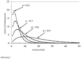
- illustration 1 shows the product distributions calculated from the above formulas as a function of the chain growth probability ⁇ .
- cobalt catalyzed FTS typically produces more methane and less ethane / ethene than calculated by (A) SF.
- the chain growth probability ⁇ is in the range of 0.6-0.8, preferably 0.65-0.75, and more preferably about 0.7.
- a high selectivity to olefins, preferably 1-olefins, as z. B. arise in the HTFT, or even a higher selectivity can be achieved.
- Inventive conditions for carrying out the method described in the context of the present invention can be found by way of example in the examples below.
- the products according to the invention are particularly suitable for use in subsequent subsequent synthesis processes.
- the products obtained are suitable for use as starting material for hydroformylations.
- the hydrocarbons of the Fischer-Tropsch process carried out in a) can be used directly in the hydroformylation stage c) without any substantial purification or its further processing, removing unwanted constituents such as non-olefins.
- the hydrocarbons may be worked up from the Fischer-Tropsch reaction step a) by removing unwanted constituents therefrom and / or separating a particular olefinic constituent therefrom.
- This work-up typically involves distillation and may include conventional, vacuum, extractive or reactive distillation. Instead, or in addition, the work-up may include techniques such as membrane separation. Olefin content and distribution of the feedstock for the hydroformylation step can thus be tailored to the required oxygenated products.
- an olefin product having a certain or multiple carbon number from the Fischer-Tropsch stage can be further processed to produce narrower "cuts" in which linear alpha-olefins are concentrated. When using such cuts as starting material for the hydroformylation, so hydroformylation products can be obtained with increased linearity.
- the carbon monoxide and hydrogen required for the hydroformylation are typically in the form of synthesis gas, which may then be the same as that used in the Fischer-Tropsch stage.
- the hydroformylation is carried out according to the in WO 2009/080396 described method.
- This is it is a one-step continuous process for hydroformylation in the presence of unmodified cobalt catalysts in a process in which catalyst formation, catalyst extraction and hydroformylation occur in the same reactor in the presence of an aqueous and an organic phase.
- an aqueous cobalt salt solution is fed into the reactor, discharged as an aqueous phase with the liquid reaction mixture and the gas phase from the reactor and continuously maintained a portion of the aqueous bottom phase from the reactor to keep constant the state of the aqueous bottom phase.
- This method is particularly suitable here, as it also olefins having at least 5 carbon atoms can be converted to the corresponding aldehydes and / or alcohols.
- the formation of the active cobalt catalyst from an aqueous cobalt salt solution, extraction of the active catalyst from the aqueous phase into the organic phase, and hydroformylation occur simultaneously in the reactor, with more aqueous cobalt salt solution being fed to the reactor as the aqueous phase with the liquid reaction mixture and is discharged together with the excess synthesis gas from the reactor.
- the excess of aqueous phase is removed by continuously withdrawing a portion of the aqueous subphase.
- cobalt salts of carboxylic acids such as, for example, cobalt formate or cobalt acetate.
- solutions which contain more than one cobalt compound are also possible.
- the cobalt solution is one which is obtained in a particularly preferred embodiment of the overall process, namely in the oxidative decarboxylation of the Hydroformyl istsautrags.
- This solution, which also contains formic acid can be used directly or after concentration or after reduction of the formic acid content, for example as in DE 100 09 207 described, are used.
- the hydroformylation is carried out in the temperature range from 110 to 250.degree. C., preferably in the temperature range from 130 to 220.degree. C., very particularly preferably in the temperature range from 160.degree. C. to 190.degree.
- the reaction pressure is in the range of 100 to 400 bar, in particular in the range of 150 to 300 bar.
- the mixture of hydrogen and carbon monoxide the volume ratio of hydrogen to carbon monoxide is preferably in the range of 1: 2 to 2: 1
- the hydroformylation according to the in WO 2017/080690 described method in WO 2017/080690 described method.
- a catalyst system which contains rhodium as the central atom and is complexed with the ligand (1):
- IUPAC designation of ligand (1) is 3,3'-di-tert-butyl-5,5'-dimethoxy- [1,1'-biphenyl] -2,2'-diyltetrakis (2,4-dimethylphenyl) bis (phosphite).
- the hydroformylation is carried out in particular at a temperature between 120 ° C and 140 ° C.
- the pressure is preferably between 15 * 10 5 Pa and 25 * 10 5 Pa.
- the hydroformylation is carried out in the presence of an organic amine of the formula (2), wherein Ra, Rb, Rc, Rd, Re and Rf are identical or different hydrocarbon radicals, which may also be interconnected.
- the organic amine preferably has at least one 2,2,6,6-tetramethylpiperidine unit. Concretely, the organic amine may be sebacic di-4- (2,2,6,6-tetramethylpiperidinyl) ester.
- the ligand / rhodium ratio should be between 1: 1 to 100: 1, wherein in addition to the organophosphorus compound according to formula (1) no further ligand is to be provided as part of the homogeneous catalyst system.
- organophosphorus compounds other than 3,3'-di-tert-butyl-5,5'-dimethoxy- [1,1'-biphenyl] -2,2'-diyltetrakis (2, 4-dimethylphenyl) bis (phosphite) complex as part of the catalyst system to the rhodium.
- impurities are not to be considered at the indicated ligand / rhodium ratio. This statement refers only to ligand (1) and it is intended that no additional ligand be provided.
- reaction mixtures of the hydroformylation are expediently freed from the catalyst. If a cobalt catalyst has been used, this can be done by depressurization, oxidation of the cobalt carbonyl compounds remaining in the hydroformylation mixture in the presence of water or aqueous acid and separation of the aqueous phase. Decoblocking processes are well known, see e.g. B. J. Falbe, a. a. O., Kirk-Othmer, a. a. O., 164, 175, BASF method.
- a wet-impregnated Mn promoted catalyst was used.
- the support consisting of mesoporous SiO 2 (Aerolyst® 3041), was impregnated with an aqueous solution of Co (NO 3 ) 2 and Mn (NO 3 ) 2 , the composition of the solution being chosen so that the later fresh catalyst was the Composition 1.5 wt .-% Mn and 10 wt .-% Co, each based on the total mass of the catalyst had.
- After drying this precursor it was heated in a vertical tubular furnace at a heating rate of 3 K / min in flowing air to 350 ° C and held at this temperature for 2 hours to obtain the fresh catalyst after cooling to room temperature.
- the activation of the catalyst and the execution of the reaction was carried out in a reactor system consisting of a gas feed with mass flow controllers, the stainless steel reactor tube (inner diameter 14 mm, outer diameter 18 mm), and a back pressure regulator.
- the reactor tube is surrounded by an aluminum tube (inner diameter 18 mm, outer diameter 18 cm), which can be heated with a heating jacket.
- Ambient pressure are collected at 0 ° C liquid products in a tempered with ice water cold trap and the hydrocarbon phase examined offline by gas chromatography.
- the gas stream exiting the cold trap is mixed with a gas stream consisting of 1% by volume of cyclopropane in N 2 as an internal standard and analyzed in a gas (CO, H 2 , CO 2 CH 4 ) and an online GC (KW). analyzed.
- the catalyst was used as a fine grain (d P ⁇ 150 microns) to prevent possible disturbing diffusion influences. Furthermore, for this example, the catalyst was diluted with nonporous SiO 2 powder in order to exclude possible temperature gradients in the fixed bed. To activate the catalyst, the catalyst bed was poured into flowing gas at ambient pressure. initially heated with 20 vol .-% H 2 in N 2 at 3 K / min to 360 ° C and held at this temperature for 3 h. Subsequently, the bed was passed through with pure H 2 for a further 2 h and then cooled again in flowing H 2 .
- the reactor was flushed with synthesis gas consisting of 2 parts H 2 and 1 part CO, and brought to the operating pressure of 33 bar. Thereafter, the catalyst bed was slowly heated to 220 ° C and maintained at steady state for 1 week to reach steady state conditions.
- the catalyst loading during the entire test duration was 1.8 l STP h -1 g Cat -1 .
- the CO conversion in the steady state was 14%, the selectivities obtained are listed in Table 1.
- Example 2 The preparation and activation of the catalyst and the reaction procedure in Example 2 were carried out analogously to the details in Example 1. The experiment was carried out at 11 bar pressure, 220 ° C and with synthesis gas consisting of 2 parts H 2 and 1 part CO. The catalyst loading during the entire test duration was 1.9 l STP h -1 g Kaf - 1 . The CO conversion in the steady state was 12%, the selectivities obtained are listed in Table 1.
- Example 3 The preparation and activation of the catalyst and the reaction procedure in Example 3 were carried out analogously to the details in Example 1.
- the catalyst was prepared so that it has the composition 5.4 wt .-% Mn and 11 wt .-% Co, based on the total mass of the catalyst.
- the experiment was carried out at 20 bar pressure, 210 ° C and with synthesis gas consisting of 2 parts H 2 and 1 part CO.
- the catalyst loading during the entire test duration was 1.6 l STP h -1 g Kaf - 1 .
- the CO conversion in the steady state was 13%, the selectivities obtained are listed in Table 1.
- Table 1 Comparison of the selectivities from the examples with literature data for the (Fe-catalyzed) HTFT (SASOL Synthol method) and estimated for the co-catalyzed LTFT (Shell Heavy Paraffin Synthesis). From 100% different sums are due to rounding.
- Literature 1 HTFT [% w / w] Calculates 2 LTFT [weight%] methane 13 12 10 10 1 ethene 2 1 1 4 0 Ethan 3 2 3 6 2 propene 12 8th 11 12 0 propane 5 3 4 2 2 butenes 10 8th 9 8th 0 butane 5 3 5 1 3 Cr 5 -Cr 11 34 39 32 39 26 C 12 -C 18 5 14 5 5 5 24 C 19 -C 21 1 1 0 1 8th C 22 -C 30 1 1 0 3 17 C 31+ 0 0 0 2 17 CO 2 ⁇ 1 ⁇ 1 ⁇ 1 kA kA O-containing compounds 10 7 17 7 kA 1 de Klerk, A; Fischer-Tropsch Refining. Wiley-VCH, 2011 2 Calculated from ASF for ⁇
Landscapes
- Chemical & Material Sciences (AREA)
- Engineering & Computer Science (AREA)
- Organic Chemistry (AREA)
- Chemical Kinetics & Catalysis (AREA)
- Materials Engineering (AREA)
- Oil, Petroleum & Natural Gas (AREA)
- Physics & Mathematics (AREA)
- Thermal Sciences (AREA)
- General Chemical & Material Sciences (AREA)
- Organic Low-Molecular-Weight Compounds And Preparation Thereof (AREA)
Abstract
Die vorliegende Erfindung betrifft ein Fischer-Tropsch-Verfahren zur Synthese von Kohlenwasserstoffen, umfassend das Inkontaktbringen von Synthesegas mit mindestens einem Katalysator, wobei der Katalysator Co und Mn sowie einen oxidischen Träger enthält.
Description
- Die vorliegende Erfindung betrifft ein Fischer-Tropsch-Verfahren zur Synthese von Kohlenwasserstoffen, umfassend das Inkontaktbringen von Synthesegas mit mindestens einem Katalysator, wobei der Katalysator Co und Mn sowie einen oxidischen Träger enthält.
- Bei dem als Fischer-Tropsch-Synthese (FTS) bekannten Verfahren werden als Reaktionsgase Mischungen aus Kohlenmonoxid und Wasserstoff, allgemein bekannt als Synthesegas, an einem heterogenen Katalysator bei erhöhter Temperatur und erhöhtem Druck zu einem Gemisch aus niederen gasförmigen und höheren flüssigen Kohlenwasserstoffen, bestehend aus Alkanen, Alkenen und Alkanolen gemäß
nCO + (2n + 1)H2→ CnH2n+2+nH2O (Alkane)
nCO + (2n)H2 → CnH2n + nH2O (Alkene)
nCO + (2n)H2 → CnH2n+1OH + (n - 1)H2O (Alkanole) umgesetzt.
Das Synthesegas als Edukt der Fischer-Tropsch-Synthese wird dafür großtechnisch aus anderen kohlenstoffhaltigen Verbindungen, wie z. B. Erdgas oder Kohle, in neuerer Zeit fast ausschließlich Erdgas, durch z. B. Vergasung, partielle Oxidation oder Dampfreformierung gewonnen. - Technisch kommen feste Katalysatoren auf Basis von Eisen oder Kobalt zur Anwendung. Kobalt wird meist auf Katalysatorträgern aus Metalloxiden, beispielsweise von Aluminium-, Titan- oder Siliziumoxiden, aufgebracht. Im Gegensatz dazu wird Eisen als Vollkontakt eingesetzt. Beide Katalysatortypen enthalten in der Regel noch Promotoren.
- Prinzipiell werden bei der Fischer-Tropsch-Synthese je nach Reaktionstemperatur zwei verschiedene Verfahren unterschieden.
Die sogenannte Tieftemperatur-Fischer-Tropsch-Synthese (LTFT; Low Temperature Fischer-Tropsch) wird technisch bei 200 bis 250 °C und Drücken größer 20 bar durchgeführt.
In der LTFT werden fast ausschließlich kobaltbasierte Katalysatoren verwendet. Diese haben erheblich längere Standzeiten als eisenbasierte Katalysatoren und werden entweder in Blasensäulen- oder Rohrbündelreaktoren eingesetzt. Das von kobaltbasierten Katalysatoren erzeugte Produkt besteht dabei bevorzugt aus langkettigen n-Paraffinen. - Die Hochtemperatur-Fischer-Tropsch-Synthese (HTFT; High Temperature Fischer-Tropsch) wird bei etwa 340 °C und bei ca. 25 bar durchgeführt. Bei beiden Verfahren wird nach dem heutigem Stand der Technik eine unterschiedliche Produktzusammensetzung erhalten.
Zielprodukte der HTFT sind lineare kurzkettige Kohlenwasserstoffe mit einem hohen Olefinanteil, typischerweise im Siedebereich von Benzin. Als Koppelprodukte werden, wie bei der LTFT, Wasser und üblicherweise v.a. bei Verwendung von Eisen als Katalysator zusätzlich erhebliche Mengen an CO2 gebildet. Da Co-basierte Katalysatoren bei hohen Temperaturen eine sehr hohe Selektivität zu Methan und niedrige Selektivitäten zu Olefinen aufweisen, werden diese bei der HTFT nicht eingesetzt. Eisen-basierte Katalysatoren begünstigen allerdings bei hohen Temperaturen die Bildung und Abscheidung von Kohlenstoff, was zu kurzen Standzeiten führt. Das hat zur Folge, dass der Fe-Katalysator häufig erneuert werden muss. Dies macht nach heutigem Stand der Technik den Einsatz von Wirbelbettreaktoren notwendig, um im laufenden Betrieb den Katalysator auszutauschen. Wirbelschichtreaktoren ermöglichen zwar durch die gute Durchmischung eine gute Wärmeabfuhr, weisen aber auch erhebliche Nachteile gegenüber den bei der LTFT eingesetzten Reaktortypen auf: Die gute Durchmischung führt zu niedrigeren Eduktkonzentrationen im Reaktor, was die Reaktionsrate verringert. Die Bewegung der Katalysatorpartikel führt außerdem zu Abrieb an Katalysator und Reaktorwand. - Aufgabe der vorliegenden Erfindung ist die Bereitstellung eines alternativen Verfahrens, das analog der Fischer-Tropsch-Synthese zu Produkten, vor allem aus linearen kurzkettigen Kohlenwasserstoffen mit einem hohen Olefinanteil, führt.
- Diese Aufgabe wird durch Verfahren gemäß der vorliegenden Erfindung gelöst.
- Gegenstand der vorliegenden Erfindung ist demgemäß ein Fischer-Tropsch-Verfahren zur Synthese von Kohlenwasserstoffen, umfassend das Inkontaktbringen von Synthesegas mit mindestens einem Katalysator unter einem Gesamtdruck zwischen 1 und 100 bar, bei einer Temperatur zwischen 180 und 250 °C, wobei der Katalysator Co und Mn sowie einen oxidischen Träger enthält.
- Es hat sich überraschend gezeigt, dass mit dem Einsatz eines Co-basierten Katalysators, der unter LTFT-typischen Bedingungen Kohlenwasserstoffe erzeugt, die in ihrer Zusammensetzung dem Produkt der HTFT sehr ähnlich sind. Dies war für den Fachmann nicht zu erwarten.
Im Gegensatz zur Fe-katalysierten HTFT entsteht dabei aber kaum unerwünschtes CO2. Damit kann in Blasensäulen- oder Rohrbündelreaktoren ein Produkt erzeugt werden, das nach derzeitigem Stand der Technik bisher nur in Wirbelbettreaktoren erzeugt werden kann. - Wesentlich im Rahmen der vorliegenden Erfindung ist der eingesetzte Katalysator, der Co und Mn sowie einen oxidischen Träger enthält. Dabei ist erfindungswesentlich, dass bei den eingesetzten Katalysatoren auf den Einsatz von Edelmetallen als Reduktionspromotoren verzichtet wird. Der eingesetzte Katalysator enthält damit neben Co und Mn keine weiteren katalytisch aktiven Metalle oder Promotoren. Dies führt zu einer deutlichen Vergünstigung und Vereinfachung der eingesetzten Katalysatoren.
- Als oxidische Träger eignen sich vorzugsweise poröses Aluminiumoxid oder Siliziumoxid, wobei Siliziumoxid ganz besonders bevorzugt ist. In einer besonders bevorzugten Ausführungsform besteht der erfindungsgemäße eingesetzte Katalysator nur aus Co, Mn und Siliziumoxid.
- Der eingesetzte Co-Katalysator wird über Nassimprägnation von entsprechenden Co- und Mn-Salzen in einen entsprechenden porösen Träger hergestellt. Bevorzugt werden als Co- und Mn-Salze Co-Nitrat und Mn-Nitrat eingesetzt, insbesondere als wässrige Lösungen. Die so erhaltenen Präkatalysatoren werden dann anschließend zu den erfindungsgemäß eingesetzten Katalysatoren kalziniert.
Die Kalzination erfolgt bei Temperaturen von 300 bis 600 °C, vorzugsweise bei 300 bis 400 °C und insbesondere bei Temperaturen um 350 °C. - In den erfindungsgemäßen Katalysatoren liegt der Co-Gehalt bei 5 bis 50 Gew.-%, vorzugsweise bei 5 bis 30 Gew.-%, insbesondere 10-30 Gew.-%, bezogen auf den Katalysator und bestimmt als Metall.
Der Gehalt an Mn beträgt 5 bis 55 Gew.-%, vorzugsweise 10 bis 30 Gew.-%, bezogen auf den Gehalt an Co und bestimmt als Metall. - Bei den erfindungsgemäß eingesetzten Reaktoren handelt es sich entweder um Blasensäulensuspensionsreaktoren oder Festbettreaktoren mit oder ohne Kreislaufführung, die bei Gesamtdrücken bis 100 bar und erhöhten Temperaturen betrieben werden können. Diese Reaktoren können mit Synthesegas, bestehend aus H2 und CO, durchströmt werden. Dabei kann das Verhältnis der beiden Gase (H2 zu CO) am Reaktoreingang im Bereich von 0,3 : 1 bis 10 : 1, vorzugsweise 0,5 : 1 bis 4:1 und insbesondere bei ungefähr 2 : 1 variiert werden. Auch kann dem Eduktgas als Verdünnung eine inerte Komponente wie z. B. N2 oder ein Edelgas beigemischt werden.
- Es hat sich im Rahmen der vorliegenden Erfindung überraschend gezeigt, dass Bedingungen, die denen der LTFT entsprechen, also um die 200 °C und Drücken im niedrigen zweistelligen (in bar) Bereich, Produkte erhalten werden, die in der Zusammensetzung annähernd denen der HTFT entsprechen.
- Ziel ist ein möglichst olefinreiches Produkt mit möglichst geringem Anteil an Methan und CO2. In erster Näherung kann die Verteilung der Kettenlängen mit der Verteilung von Produkten einer Polymerisationsreaktion nach Schulz-Flory ((SF), häufig für die Fischer-Tropsch-Synthese auch als Anderson-Schulz-Flory-Verteilung (ASF) bezeichnet) beschrieben werden:

In der FTS wird oft auch die massenbezogene Verteilung gewählt:
-
Abbildung 1 zeigt die aus den genannten Formeln berechneten Produktverteilungen in Abhängigkeit von der Kettenwachstumswahrscheinlichkeit α. - Bei der Cobalt katalysierten FTS entsteht allerdings typischerweise mehr Methan und weniger Ethan/Ethen als durch die (A)SF berechnet.
- Im Rahmen der vorliegenden Erfindung ist die Kettenwachstumswahrscheinlichkeit α im Bereich von 0,6 - 0,8, vorzugsweise 0,65 -0,75 und insbesondere bevorzugt bei rund 0,7.
Dabei kann eine hohe Selektivität zu Olefinen, bevorzugt 1-Olefinen, wie sie z. B. in der HTFT entstehen, oder sogar eine höhere Selektivität erreicht werden. Erfindungsgemäße Bedingungen für die Durchführung des im Rahmen der vorliegenden Erfindung beschriebenen Verfahrens finden sich exemplarisch in den nachfolgend genannten Beispielen. - Die erfindungsgemäß hergestellten Produkte eignen sich in besonderer Weise für den Einsatz in weiteren sich anschließenden Syntheseprozessen. Insbesondere eignen sich die erhaltenen Produkte für den Einsatz als Ausgangsstoff für Hydroformylierungen.
- Somit ist ein weiterer Gegenstand der vorliegenden Erfindung ein Verfahren zur Herstellung oxygenierter Produkte, insbesondere Aldehyde und Alkohole, umfassend die Verfahrensschritte:
- a) Durchführen eines Fischer-Tropsch-Verfahrens zur Synthese von Kohlenwasserstoffen, umfassend das Inkontaktbringen von Synthesegas mit mindestens einem Katalysator unter einem Gesamtdruck zwischen 1 und 100 bar, bei einer Temperatur zwischen 180 und 250 °C, wobei der Katalysator Co und Mn sowie einen oxidischen Träger enthält,
- b) gegebenenfalls Aufreinigung der erhaltenen Kohlenwasserstoffe
- c) Durchführen einer Hydroformylierung mit Kohlenmonoxid und Wasserstoff in Gegenwart einer katalytisch wirksamen Menge eines Hydroformylierungskatalysators unter Erhalt der oxygenierten Produkte.
- In einer ersten bevorzugten Ausführungsform der vorliegenden Erfindung können die Kohlenwasserstoffe des in a) durchgeführten Fischer-Tropsch-Verfahrens direkt in der Hydroformylierungsstufe c) ohne irgendeine wesentliche Reinigung oder dessen weiteres Verarbeiten unter Entfernen unerwünschter Bestandteile wie etwa Nichtolefinen verwendet werden.
- In einer alternativen bevorzugten Ausführungsform der vorliegenden Erfindung können die Kohlenwasserstoffe aus der Fischer-Tropsch-Reaktionsstufe a) unter Entfernen unerwünschter Bestandteile daraus und/oder Abtrennen eines besonderen olefinischen Bestandteils daraus aufgearbeitet werden. Diese Aufarbeitung umfasst typischerweise eine Destillation und kann eine herkömmliche, Vakuum-, extraktive oder reaktive Destillation umfassen. Stattdessen oder zusätzlich kann die Aufarbeitung Techniken wie etwa Membrantrennung umfassen. Olefingehalt und -verteilung des Einsatzmaterials für die Hydroformylierungsstufe können so entsprechend den geforderten sauerstoffhaltigen Produkten maßgeschneidert werden. So kann ein Olefinprodukt mit einer bestimmten oder mehrfachen Kohlenstoffzahl aus der Fischer-Tropsch-Stufe zum Herstellen engerer "Schnitte", in denen lineare α-Olefine konzentriert sind, weiter verarbeitet werden. Bei Einsatz derartiger Schnitte als Ausgangsmaterial für die Hydroformylierung, können so Hydroformylierungsprodukte mit erhöhter Linearität erhalten werden.
- Das für die Hydroformylierung erforderliche Kohlenmonoxid sowie der Wasserstoff liegen typischerweise in der Form von Synthesegas vor, das dann dasselbe wie das in der Fischer-Tropsch-Stufe verwendete sein kann.
- Entsprechende Hydroformulierungsverfahren sind dem Fachmann bekannt und beispielsweise in Hydroformylation Fundaments, Procceses and Applications in Organic Synthesis Volume 1 & 2 Auflage 1, Franke, Börner, Willey VCH Verlag GmbH & Co, Weinheim beschrieben.
- Man arbeitet in der Regel mit Rhodium- oder Kobaltkatalysatoren sowie mit oder ohne komplexstabilisierenden Zusätzen, wie organischen Phosphinen oder Phosphiten. Die Temperaturen und Drücke können, je nach Katalysator oder Olefin, in weiten Grenzen variieren. Eine Beschreibung der Hydroformylierung von Olefinen findet sich z. B. bei J. Falbe, New Syntheses with Carbon Monoxide, Springer-Verlag, Heidelberg-New York, 1980, Seite 99 ff. sowie bei Kirk-Othmer, Encyclopedia of Chemical Technology, Band 17, 4. Auflage, John Wiley & Sons, Seiten 902 bis 919 (1996).
- In einer ersten bevorzugten Ausführungsform der vorliegenden Erfindung erfolgt die Hydroformylierung nach dem in
WO 2009/080396 beschriebenen Verfahren. Hierbei handelt es sich um ein einstufiges kontinuierliches Verfahren zur Hydroformylierung in Gegenwart von unmodifizierten Kobaltkatalysatoren in einem Prozess, bei dem bei Vorliegen einer wässrigen und einer organischen Phase Katalysatorbildung, Katalysatorextraktion und Hydroformylierung im gleichen Reaktor erfolgt. Dabei wird eine wässrige Kobaltsalzlösung in den Reaktor eingespeist, als wässrige Phase mit dem flüssigen Reaktionsgemisch und der Gasphase aus dem Reaktor ausgetragen und zur Konstanthaltung des Stands der wässrigen Sumpfphase kontinuierlich ein Teil der wässrigen Sumpfphase aus dem Reaktor gefahren. Dieses Verfahren eignet sich hier insbesondere, da damit auch Olefine mit mindestens 5 Kohlenstoffatomen zu den entsprechenden Aldehyden und/oder Alkoholen umgesetzt werden können. - Bei dem beschriebenen Verfahren erfolgt die Bildung des aktiven Kobaltkatalysators aus einer wässrigen Kobaltsalzlösung, Extraktion des aktiven Katalysators aus der wässrigen Phase in die organische Phase und Hydroformylierung gleichzeitig im Reaktor, wobei mehr wässrige Kobaltsalzlösung in den Reaktor eingespeist wird, als wässrige Phase mit dem flüssigen Reaktionsgemisch und mit dem überschüssigen Synthesegas zusammen aus dem Reaktor ausgetragen wird. Der Überschuss an wässriger Phase wird durch kontinuierliches Abziehen eines Teils der wässrigen Unterphase entfernt.
- Dabei werden 2 bis 99 Massen-%, insbesondere 5 bis 80 Massen-% und ganz besonders 10 bis 60 Massen-% des in den Reaktor mit der Kobaltsalzlösung eingespeisten Wassers durch Abziehen eines Teils der wässrigen Unterphase entfernt.
- Bevorzugt werden wässrige Lösungen von Kobaltsalzen von Carbonsäuren, wie beispielsweise Kobaltformiat oder Kobaltacetat, eingesetzt. Es können auch Lösungen, die mehr als eine Kobaltverbindung enthalten, eingesetzt werden. Vorzugsweise ist die Kobaltlösung eine solche, die bei einer besonders bevorzugten Ausführung des Gesamtprozesses, nämlich bei der oxidativen Entkobaltung des Hydroformylierungsautrags, anfällt. Diese Lösung, die auch Ameisensäure enthält, kann direkt oder nach Aufkonzentrierung oder nach Reduzierung des Ameisensäuregehalts, beispielsweise wie in
DE 100 09 207 beschrieben, eingesetzt werden. - Die Hydroformylierung wird im Temperaturbereich von 110 bis 250 °C, bevorzugt im Temperaturbereich von 130 bis 220 °C, ganz besonders bevorzugt im Temperaturbereich von 160 °C bis 190 °C durchgeführt.
- Der Reaktionsdruck liegt im Bereich von 100 bis 400 bar, insbesondere im Bereich von 150 bis 300 bar. Im eingesetzten Synthesegas, dem Gemisch aus Wasserstoff und Kohlenstoffmonoxid, liegt das Volumenverhältnis von Wasserstoff zu Kohlenstoffmonoxid vorzugsweise im Bereich 1 zu 2 bis 2 zu 1
- In einer weiteren Ausführungsform der vorliegenden Erfindung kann die Hydroformylierung gemäß dem in
WO 2017/080690 beschriebenen Verfahren erfolgen.
Dabei wird in der Hydroformylierung ein Katalysatorsystem eingesetzt, das Rhodium als Zentralatom enthält und mit dem Liganden (1) komplexiert ist:
- Die IUPAC Bezeichnung von Ligand (1) ist 3,3'-di-tert-butyl-5,5'-dimethoxy-[1,1'-biphenyl]-2,2'-diyltetrakis(2,4-dimethylphenyl)bis(phosphite).
- Die Hydroformylierung erfolgt insbesondere bei einer Temperatur zwischen 120 °C und 140 °C. Der Druck liegt vorzugsweise zwischen 15*105 Pa und 25*105 Pa.
Um die Betriebsdauer zu verlängern, wird die Hydroformylierung in Gegenwart eines organischen Amins der Formel (2) durchgeführt,
- Es wird empfohlen, eine Rhodiumkonzentration im ersten Reaktionsgemisch zwischen 1 Gew.-ppm und 1000 Gew.-ppm einzustellen. Das Ligand/Rhodium-Verhältnis sollte zwischen 1:1 bis 100:1 betragen, wobei neben der Organophosphorverbindung gemäß Formel (1) kein weiterer Ligand als Teil des homogenen Katalysatorsystems vorzusehen ist. Im industriellen Betrieb ist nicht auszuschließen, dass aufgrund von Verunreinigungen andere Organophosphorverbindungen als 3,3'-di-tert-butyl-5,5'-dimethoxy-[1,1'-biphenyl]-2,2'-diyltetrakis(2,4-dimethylphenyl)bis(phosphite) als Teil des Katalysatorsystems an das Rhodium komplexieren. Derartige Verunreinigungen sind aber bei dem angegebenen Ligand/Rhodium-Verhältnis nicht zu berücksichtigen. Diese Angabe bezieht sich einzig auf Ligand (1) und in beabsichtigter Weise muss kein weiterer Ligand vorgesehen sein.
- Die Reaktionsgemische der Hydroformylierung werden zweckmäßigerweise vom Katalysator befreit. Wenn ein Kobaltkatalysator verwendet worden ist, kann dies durch Druckentlastung, Oxidation der im Hydroformylierungsgemisch verbliebenen Kobaltcarbonylverbindungen in Gegenwart von Wasser oder wässriger Säure und Abtrennung der wässrigen Phase geschehen. Entkobaltungsverfahren sind gut bekannt, siehe z. B. J. Falbe, a. a. O., Kirk-Othmer, a. a. O., 164, 175, BASF-Verfahren.
- Wenn eine Rhodiumverbindung als Hydroformylierungskatalysator eingesetzt wird, kann man diese z. B. mittels Dünnschichtverdampfung als Destillationsrückstand abtrennen
- Auch ohne weitere Ausführungen wird davon ausgegangen, dass ein Fachmann die obige Beschreibung im weitesten Umfang nutzen kann. Die bevorzugten Ausführungsformen und Beispiele sind deswegen lediglich als beschreibende, keinesfalls als in irgendeiner Weise limitierende Offenbarung aufzufassen.
Nachfolgend wird die vorliegende Erfindung anhand eines Beispiels näher erläutert. Alternative Ausführungsformen der vorliegenden Erfindung sind in analoger Weise erhältlich. - Es wurde ein durch Nassimprägnierung hergestellter Mn promotierter Katalysator verwendet. Der Träger, bestehend aus mesoporösen SiO2 (Aerolyst® 3041), wurde mit einer wässrigen Lösung aus Co(NO3)2 und Mn(NO3)2 imprägniert, wobei die Zusammensetzung der Lösung so gewählt wurde, das der spätere frische Katalysator die Zusammensetzung 1,5 Gew.-% Mn und 10 Gew.-% Co, jeweils bezogen auf die Gesamtmasse des Katalysators, aufwies. Nach Trocknen dieses Präkursors wurde dieser in einem vertikalen Röhrenofen mit einer Heizrate von 3 K/min in strömender Luft auf 350 °C aufgeheizt und bei dieser Temperatur 2 h gehalten, um nach dem Abkühlen auf Raumtemperatur den frischen Katalysator zu erhalten.
- Die Aktivierung des Katalysators und die Durchführung der Reaktion wurde in einem Reaktorsystem bestehend aus einer Gaszuführung mit Massendurchflussreglern, dem aus Edelstahl bestehendem Reaktorrohr (Innendurchmesser 14 mm, Außendurchmesser 18 mm), und einem Rückdruckregler durchgeführt. Das Reaktorrohr ist von einem Aluminiumrohr (Innendurchmesser 18 mm, Außendurchmesser 18 cm), welches mit einer Heizmanschette beheizt werden kann, umgeben. Nach Entspannung des Abgases durch den Rückdruckregler auf Umgebungsdruck werden die bei 0 °C flüssigen Produkte in einer mit Eiswasser temperierten Kühlfalle gesammelt und die Kohlenwasserstoffphase offline Gaschromatographisch untersucht. Der Gasstrom, der die Kühlfalle verlässt, wird mit einem Gasstrom bestehend aus 1 vol.-% Cyclopropan in N2 als interner Standard vermischt und in einer Gasanalyse (CO, H2, CO2 CH4) und einem online-GC (KW) analysiert.
- Die Aktivierung des Katalysators erfolgte direkt vor der Durchführung der Fischer-Tropsch-Synthese in dem oben genannten Reaktorsystem. Der Katalysator wurde als Feinkorn (dP < 150 µm) eingesetzt, um mögliche störende Diffusionseinflüsse zu verhindern. Weiterhin wurde für dieses Beispiel der Katalysator mit unporösem SiO2 - Pulver verdünnt, um mögliche Temperaturgradienten im Festbett auszuschließen.
Zur Aktivierung des Katalysators wurde die Katalysatorschüttung in fließendem Gas bei Umgebungsdruck. zunächst mit 20 vol.-% H2 in N2 mit 3 K/min auf 360 °C aufgeheizt und bei dieser Temperatur 3 h gehalten. Im Anschluss wurde die Schüttung weitere 2 h mit reinem H2 durchströmt und dann in fließenden H2 wieder abgekühlt.
Nach der Aktivierung wurde der Reaktor mit Synthesegas, bestehend aus 2 Teilen H2 und 1 Teil CO, gespült und auf den Betriebsdruck von 33 bar gebracht. Daraufhin wurde das Katalysatorbett langsam auf 220 °C aufgeheizt und zur Erreichung des stationären Zustands 1 Woche bei diesen Bedingungen gehalten. Die Katalysatorbelastung betrug dabei während der gesamten Versuchsdauer 1,8 ISTP h-1 gKat -1. Der CO - Umsatz im stationären Zustand betrug 14 %, die erhaltenen Selektivitäten sind in Tabelle 1 aufgeführt. - Die Herstellung und Aktivierung des Katalysators und die Reaktionsdurchführung in Beispiel 2 erfolgte analog zu den Angaben in Beispiel 1. Der Versuch wurde bei 11 bar Druck, 220 °C und mit Synthesegas, bestehend aus 2 Teilen H2 und 1 Teil CO durchgeführt. Die Katalysatorbelastung betrug dabei während der gesamten Versuchsdauer 1,9 ISTP h-1 gKaf-1. Der CO - Umsatz im stationären Zustand betrug 12 %, die erhaltenen Selektivitäten sind in Tabelle 1 aufgeführt.
- Die Herstellung und Aktivierung des Katalysators und die Reaktionsdurchführung in Beispiel 3 erfolgte analog zu den Angaben in Beispiel 1. Der Katalysator wurde so hergestellt, dass er die Zusammensetzung 5,4 Gew.-% Mn und 11 Gew.-% Co, jeweils bezogen auf die Gesamtmasse des Katalysators, aufwies. Der Versuch wurde bei 20 bar Druck, 210 °C und mit Synthesegas, bestehend aus 2 Teilen H2 und 1 Teil CO durchgeführt. Die Katalysatorbelastung betrug dabei während der gesamten Versuchsdauer 1,6 ISTP h-1 gKaf-1. Der CO - Umsatz im stationären Zustand betrug 13 %, die erhaltenen Selektivitäten sind in Tabelle 1 aufgeführt.
Tabelle 1: Vergleich der Selektivitäten aus den Beispielen mit Literaturdaten für die (Fe-katalysierte) HTFT (SASOL Synthol Verfahren) und abgeschätzt für die Co-katalysierte LTFT (Shell Heavy Paraffin Synthesis). Von 100% abweichende Summen sind rundungsbedingt. Beispiel 1 [Gew.c-%] (α = 0,72) Beispiel 2 [Gew.c-%] (α = 0,75) Beispiel 3 [Gew.c-%] (α = 0,68) Literatur1 HTFT [Gew.c-%] Berechnet2 LTFT [Gew.c-%] Methan 13 12 10 10 1 Ethen 2 1 1 4 0 Ethan 3 2 3 6 2 Propen 12 8 11 12 0 Propan 5 3 4 2 2 Butene 10 8 9 8 0 Butan 5 3 5 1 3 Cr5-Cr11 34 39 32 39 26 C12-C18 5 14 5 5 24 C19-C21 1 1 0 1 8 C22-C30 1 1 0 3 17 C31+ 0 0 0 2 17 CO2 <1 <1 <1 k.A. k.A. O-haltige Verbindungen 10 7 17 7 k.A 1 de Klerk, A; Fischer-Tropsch Refining. Wiley-VCH, 2011
2 Berechnet aus ASF für α = 0,9 und C-Zahlen < 100 - Man erkennt aus den Vergleichszahlen, speziell z. B. den Selektivitäten zu Propen, den Butenen und langkettigen Produkten, dass in diesen Beispielen bei LTFT-Bedingungen ein Produkt gewonnen wurde, welches wie das Produkt der HTFT (T > 300 °C) fast ausschließlich aus bei Raumtemperatur und -druck gasförmigen und flüssigen Bestandteilen besteht und reich an Olefinen ist. Bei der LTFT hingegen entsteht ein Produkt welches über 35 Gew.-% bei RT feste Komponenten enthält.
Claims (6)
- Fischer-Tropsch-Verfahren zur Synthese von Kohlenwasserstoffen, umfassend das Inkontaktbringen von Synthesegas mit mindestens einem Katalysator unter einem Gesamtdruck zwischen 1 und 100 bar, bei einer Temperatur zwischen 180 und 250 °C, wobei der Katalysator Co und Mn sowie einen oxidischen Träger enthält.
- Verfahren gemäß Anspruch 1, dadurch gekennzeichnet, dass der Katalysator neben Co und Mn keine weiteren katalytisch aktiven Metalle oder Promotoren enthält.
- Verfahren gemäß Anspruch 1 oder 2, dadurch gekennzeichnet, dass der Katalysator nur aus Co, Mn und Siliziumoxid besteht.
- Verfahren gemäß einem oder mehreren der Ansprüche 1 bis 3, dadurch gekennzeichnet, dass der Co-Gehalt bei 5 bis 50 Gew.-% beträgt, bezogen auf den Katalysator und bestimmt als Metall.
- Verfahren gemäß einem oder mehreren der Ansprüche 1 bis 4, dadurch gekennzeichnet, dass der Gehalt an Mn 5 bis 55 Gew.-% beträgt, bezogen auf den Gehalt an Co und bestimmt als Metall.
- Verfahren zur Herstellung oxygenierter Produkte, umfassend die Verfahrensschritte:a) Durchführen eines Fischer-Tropsch-Verfahrens gemäß einem oder mehreren der Ansprüche 1 bis 5, umfassend das Inkontaktbringen von Synthesegas mit mindestens einem Katalysator unter einem Gesamtdruck zwischen 1 und 100 bar, bei einer Temperatur zwischen 180 und 250 °C, wobei der Katalysator Co und Mn sowie einen oxidischen Träger enthältb) gegebenenfalls Aufreinigung der erhaltenen Kohlenwasserstoffec) Durchführen einer Hydroformylierung mit Kohlenmonoxid und Wasserstoff in Gegenwart einer katalytisch wirksamen Menge eines Hydroformylierungskatalysators unter Erhalt der oxygenierten Produkte.
Priority Applications (1)
| Application Number | Priority Date | Filing Date | Title |
|---|---|---|---|
| EP18165489.8A EP3549996A1 (de) | 2018-04-03 | 2018-04-03 | Olefine durch fischer-tropsch-synthese |
Applications Claiming Priority (1)
| Application Number | Priority Date | Filing Date | Title |
|---|---|---|---|
| EP18165489.8A EP3549996A1 (de) | 2018-04-03 | 2018-04-03 | Olefine durch fischer-tropsch-synthese |
Publications (1)
| Publication Number | Publication Date |
|---|---|
| EP3549996A1 true EP3549996A1 (de) | 2019-10-09 |
Family
ID=61971904
Family Applications (1)
| Application Number | Title | Priority Date | Filing Date |
|---|---|---|---|
| EP18165489.8A Ceased EP3549996A1 (de) | 2018-04-03 | 2018-04-03 | Olefine durch fischer-tropsch-synthese |
Country Status (1)
| Country | Link |
|---|---|
| EP (1) | EP3549996A1 (de) |
Citations (7)
| Publication number | Priority date | Publication date | Assignee | Title |
|---|---|---|---|---|
| US5958985A (en) * | 1996-12-13 | 1999-09-28 | Shell Oil Company | Process for the preparation of hydrocarbons |
| DE10009207A1 (de) | 2000-02-26 | 2001-08-30 | Oxeno Olefinchemie Gmbh | Verbessertes Verfahren zur Hydroformylierung von Olefinen durch Reduzierung der Ameisensäurekonzentration |
| US20040214905A1 (en) * | 2000-07-03 | 2004-10-28 | Geerlings Jacobus Johannes Cornelis | Catalyst and process for the preparation of hydrocarbons |
| DE60303033T2 (de) * | 2002-06-05 | 2006-08-03 | Shell Internationale Research Maatschappij B.V. | Verfahren zur herstellung von kohlenwasserstoffen aus einer gasförmigen beschickung. |
| WO2009080396A1 (de) | 2007-12-20 | 2009-07-02 | Evonik Oxeno Gmbh | Einstufiges kontinuierliches verfahren zur hydroformylierung von höheren olefinen oder olefingemischen |
| WO2017080690A1 (de) | 2015-11-09 | 2017-05-18 | Evonik Degussa Gmbh | Wirtschaftliche herstellung von 2-propylheptanol |
| US20170297006A1 (en) * | 2013-07-24 | 2017-10-19 | Shell Oil Company | Process for preparing a chlorine comprising catalyst, the prepared catalyst, and its use |
-
2018
- 2018-04-03 EP EP18165489.8A patent/EP3549996A1/de not_active Ceased
Patent Citations (7)
| Publication number | Priority date | Publication date | Assignee | Title |
|---|---|---|---|---|
| US5958985A (en) * | 1996-12-13 | 1999-09-28 | Shell Oil Company | Process for the preparation of hydrocarbons |
| DE10009207A1 (de) | 2000-02-26 | 2001-08-30 | Oxeno Olefinchemie Gmbh | Verbessertes Verfahren zur Hydroformylierung von Olefinen durch Reduzierung der Ameisensäurekonzentration |
| US20040214905A1 (en) * | 2000-07-03 | 2004-10-28 | Geerlings Jacobus Johannes Cornelis | Catalyst and process for the preparation of hydrocarbons |
| DE60303033T2 (de) * | 2002-06-05 | 2006-08-03 | Shell Internationale Research Maatschappij B.V. | Verfahren zur herstellung von kohlenwasserstoffen aus einer gasförmigen beschickung. |
| WO2009080396A1 (de) | 2007-12-20 | 2009-07-02 | Evonik Oxeno Gmbh | Einstufiges kontinuierliches verfahren zur hydroformylierung von höheren olefinen oder olefingemischen |
| US20170297006A1 (en) * | 2013-07-24 | 2017-10-19 | Shell Oil Company | Process for preparing a chlorine comprising catalyst, the prepared catalyst, and its use |
| WO2017080690A1 (de) | 2015-11-09 | 2017-05-18 | Evonik Degussa Gmbh | Wirtschaftliche herstellung von 2-propylheptanol |
Non-Patent Citations (3)
| Title |
|---|
| "Hydroformylation Fundaments, Procceses and Applications in Organic Synthesis", vol. 1 & 2, WILLEY VCH VERLAG GMBH & CO, article FRANKE, BÖRNER |
| J. FALBE: "New Syntheses with Carbon Monoxide", 1980, SPRINGER-VERLAG, pages: 99 ff |
| KIRK-OTHMER: "Encyclopedia of Chemical Technology", vol. 17, 1996, JOHN WILEY & SONS, pages: 902 - 919 |
Similar Documents
| Publication | Publication Date | Title |
|---|---|---|
| EP3492445B1 (de) | Verfahren zur gewinnung von alkoholen aus aldehyden | |
| EP1669337B1 (de) | Verfahren zur Herstellung von Alkoholen aus Olefinen durch Hydroformylierung und Hydrierung | |
| DE69615557T2 (de) | Verfahren zur herstellung von sauerstoff enthaltenden verbindungen | |
| DE69824148T2 (de) | Verfahren, Katalysator und Vorrichtung zur Herstellung von Acetaldehyd aus Essigsäure | |
| EP3492446B1 (de) | Verfahren zur gewinnung von alkoholen aus aldehyden | |
| EP3938337B1 (de) | Verfahren und anlage zur herstellung eines oder mehrerer olefine | |
| DE69916755T2 (de) | Verfahren zur Herstellung von Alkoholen | |
| WO2003078365A2 (de) | Verfahren zur hydroformylierung von olefinen | |
| EP3492447A1 (de) | Verfahren zur gewinnung von alkoholen aus aldehyden | |
| EP1294668B1 (de) | Verfahren zur hydroformylierung von olefinen mit 2 bis 8 kohlenstoffatomen | |
| EP2288584A1 (de) | Verfahren zur abtrennung von 1-buten aus c4-haltigen kohlenwasserstoffströmen durch hydroformylierung | |
| WO2009080395A1 (de) | Mehrstufiges kontinuierliches verfahren zur hydroformylierung von höheren olefinen oder olefingemischen | |
| DE60214168T2 (de) | Verfahren zur herstellung einer in hohem grade linearen alkoholzusammensetzung | |
| DE102009027978A1 (de) | Verfahren zur Herstellung von Decancarbonsäuren | |
| WO2014170392A1 (de) | Immobilisierte katalytisch aktive zusammensetzung zur hydroformylierung von olefinhaltigen gemischen | |
| DE69116002T2 (de) | Verfahren zur Dehydrierung von Paraffinen | |
| WO2015132068A1 (de) | Verfahren zur herstellung von aldehyden aus alkanen und synthesegas | |
| EP3708558A1 (de) | Verfahren und anlage zur herstellung eines oder mehrerer olefine | |
| EP0302375A2 (de) | Verfahren zur Herstellung von Aldehyden | |
| EP3693356A1 (de) | Flexible herstellung von mtbe oder etbe und isononanol | |
| EP3708557A1 (de) | Verfahren und anlage zur herstellung eines oder mehrerer olefine | |
| EP4234528A1 (de) | Verfahren zur hydrierung von c13-aldehyden in mindestens zwei hydrierstufen | |
| DE60012912T2 (de) | Verfahren zur abtrennung funktionalisierter interner olefine | |
| DE1246724B (de) | Verfahren zur Herstellung von Cyclohexen, Methyl- oder Dimethylcyclohexen | |
| EP3693355B1 (de) | Flexible herstellung von mtbe oder etbe und isononanol |
Legal Events
| Date | Code | Title | Description |
|---|---|---|---|
| PUAI | Public reference made under article 153(3) epc to a published international application that has entered the european phase |
Free format text: ORIGINAL CODE: 0009012 |
|
| STAA | Information on the status of an ep patent application or granted ep patent |
Free format text: STATUS: THE APPLICATION HAS BEEN PUBLISHED |
|
| AK | Designated contracting states |
Kind code of ref document: A1 Designated state(s): AL AT BE BG CH CY CZ DE DK EE ES FI FR GB GR HR HU IE IS IT LI LT LU LV MC MK MT NL NO PL PT RO RS SE SI SK SM TR |
|
| AX | Request for extension of the european patent |
Extension state: BA ME |
|
| RAP1 | Party data changed (applicant data changed or rights of an application transferred) |
Owner name: EVONIK OPERATIONS GMBH |
|
| STAA | Information on the status of an ep patent application or granted ep patent |
Free format text: STATUS: THE APPLICATION HAS BEEN REFUSED |
|
| 18R | Application refused |
Effective date: 20200103 |