EP3549809A1 - Système de commande de charge-décharge pour véhicule - Google Patents
Système de commande de charge-décharge pour véhicule Download PDFInfo
- Publication number
- EP3549809A1 EP3549809A1 EP19166690.8A EP19166690A EP3549809A1 EP 3549809 A1 EP3549809 A1 EP 3549809A1 EP 19166690 A EP19166690 A EP 19166690A EP 3549809 A1 EP3549809 A1 EP 3549809A1
- Authority
- EP
- European Patent Office
- Prior art keywords
- charge
- state
- battery
- electric power
- low
- Prior art date
- Legal status (The legal status is an assumption and is not a legal conclusion. Google has not performed a legal analysis and makes no representation as to the accuracy of the status listed.)
- Granted
Links
- 230000007423 decrease Effects 0.000 claims abstract description 12
- 238000000034 method Methods 0.000 description 37
- 230000005540 biological transmission Effects 0.000 description 6
- 230000003247 decreasing effect Effects 0.000 description 5
- 238000001514 detection method Methods 0.000 description 4
- 230000000694 effects Effects 0.000 description 3
- HBBGRARXTFLTSG-UHFFFAOYSA-N Lithium ion Chemical compound [Li+] HBBGRARXTFLTSG-UHFFFAOYSA-N 0.000 description 2
- 230000002457 bidirectional effect Effects 0.000 description 2
- 238000007599 discharging Methods 0.000 description 2
- 229910001416 lithium ion Inorganic materials 0.000 description 2
- 230000007774 longterm Effects 0.000 description 2
- 230000015556 catabolic process Effects 0.000 description 1
- 238000006731 degradation reaction Methods 0.000 description 1
- 238000010586 diagram Methods 0.000 description 1
- 229910052987 metal hydride Inorganic materials 0.000 description 1
- 239000007787 solid Substances 0.000 description 1
Images

Classifications
-
- B—PERFORMING OPERATIONS; TRANSPORTING
- B60—VEHICLES IN GENERAL
- B60L—PROPULSION OF ELECTRICALLY-PROPELLED VEHICLES; SUPPLYING ELECTRIC POWER FOR AUXILIARY EQUIPMENT OF ELECTRICALLY-PROPELLED VEHICLES; ELECTRODYNAMIC BRAKE SYSTEMS FOR VEHICLES IN GENERAL; MAGNETIC SUSPENSION OR LEVITATION FOR VEHICLES; MONITORING OPERATING VARIABLES OF ELECTRICALLY-PROPELLED VEHICLES; ELECTRIC SAFETY DEVICES FOR ELECTRICALLY-PROPELLED VEHICLES
- B60L1/00—Supplying electric power to auxiliary equipment of vehicles
- B60L1/003—Supplying electric power to auxiliary equipment of vehicles to auxiliary motors, e.g. for pumps, compressors
-
- B—PERFORMING OPERATIONS; TRANSPORTING
- B60—VEHICLES IN GENERAL
- B60K—ARRANGEMENT OR MOUNTING OF PROPULSION UNITS OR OF TRANSMISSIONS IN VEHICLES; ARRANGEMENT OR MOUNTING OF PLURAL DIVERSE PRIME-MOVERS IN VEHICLES; AUXILIARY DRIVES FOR VEHICLES; INSTRUMENTATION OR DASHBOARDS FOR VEHICLES; ARRANGEMENTS IN CONNECTION WITH COOLING, AIR INTAKE, GAS EXHAUST OR FUEL SUPPLY OF PROPULSION UNITS IN VEHICLES
- B60K6/00—Arrangement or mounting of plural diverse prime-movers for mutual or common propulsion, e.g. hybrid propulsion systems comprising electric motors and internal combustion engines ; Control systems therefor, i.e. systems controlling two or more prime movers, or controlling one of these prime movers and any of the transmission, drive or drive units Informative references: mechanical gearings with secondary electric drive F16H3/72; arrangements for handling mechanical energy structurally associated with the dynamo-electric machine H02K7/00; machines comprising structurally interrelated motor and generator parts H02K51/00; dynamo-electric machines not otherwise provided for in H02K see H02K99/00
- B60K6/20—Arrangement or mounting of plural diverse prime-movers for mutual or common propulsion, e.g. hybrid propulsion systems comprising electric motors and internal combustion engines ; Control systems therefor, i.e. systems controlling two or more prime movers, or controlling one of these prime movers and any of the transmission, drive or drive units Informative references: mechanical gearings with secondary electric drive F16H3/72; arrangements for handling mechanical energy structurally associated with the dynamo-electric machine H02K7/00; machines comprising structurally interrelated motor and generator parts H02K51/00; dynamo-electric machines not otherwise provided for in H02K see H02K99/00 the prime-movers consisting of electric motors and internal combustion engines, e.g. HEVs
- B60K6/42—Arrangement or mounting of plural diverse prime-movers for mutual or common propulsion, e.g. hybrid propulsion systems comprising electric motors and internal combustion engines ; Control systems therefor, i.e. systems controlling two or more prime movers, or controlling one of these prime movers and any of the transmission, drive or drive units Informative references: mechanical gearings with secondary electric drive F16H3/72; arrangements for handling mechanical energy structurally associated with the dynamo-electric machine H02K7/00; machines comprising structurally interrelated motor and generator parts H02K51/00; dynamo-electric machines not otherwise provided for in H02K see H02K99/00 the prime-movers consisting of electric motors and internal combustion engines, e.g. HEVs characterised by the architecture of the hybrid electric vehicle
- B60K6/48—Parallel type
- B60K6/485—Motor-assist type
-
- B—PERFORMING OPERATIONS; TRANSPORTING
- B60—VEHICLES IN GENERAL
- B60L—PROPULSION OF ELECTRICALLY-PROPELLED VEHICLES; SUPPLYING ELECTRIC POWER FOR AUXILIARY EQUIPMENT OF ELECTRICALLY-PROPELLED VEHICLES; ELECTRODYNAMIC BRAKE SYSTEMS FOR VEHICLES IN GENERAL; MAGNETIC SUSPENSION OR LEVITATION FOR VEHICLES; MONITORING OPERATING VARIABLES OF ELECTRICALLY-PROPELLED VEHICLES; ELECTRIC SAFETY DEVICES FOR ELECTRICALLY-PROPELLED VEHICLES
- B60L50/00—Electric propulsion with power supplied within the vehicle
- B60L50/10—Electric propulsion with power supplied within the vehicle using propulsion power supplied by engine-driven generators, e.g. generators driven by combustion engines
- B60L50/16—Electric propulsion with power supplied within the vehicle using propulsion power supplied by engine-driven generators, e.g. generators driven by combustion engines with provision for separate direct mechanical propulsion
-
- B—PERFORMING OPERATIONS; TRANSPORTING
- B60—VEHICLES IN GENERAL
- B60L—PROPULSION OF ELECTRICALLY-PROPELLED VEHICLES; SUPPLYING ELECTRIC POWER FOR AUXILIARY EQUIPMENT OF ELECTRICALLY-PROPELLED VEHICLES; ELECTRODYNAMIC BRAKE SYSTEMS FOR VEHICLES IN GENERAL; MAGNETIC SUSPENSION OR LEVITATION FOR VEHICLES; MONITORING OPERATING VARIABLES OF ELECTRICALLY-PROPELLED VEHICLES; ELECTRIC SAFETY DEVICES FOR ELECTRICALLY-PROPELLED VEHICLES
- B60L58/00—Methods or circuit arrangements for monitoring or controlling batteries or fuel cells, specially adapted for electric vehicles
- B60L58/10—Methods or circuit arrangements for monitoring or controlling batteries or fuel cells, specially adapted for electric vehicles for monitoring or controlling batteries
- B60L58/12—Methods or circuit arrangements for monitoring or controlling batteries or fuel cells, specially adapted for electric vehicles for monitoring or controlling batteries responding to state of charge [SoC]
- B60L58/13—Maintaining the SoC within a determined range
-
- B—PERFORMING OPERATIONS; TRANSPORTING
- B60—VEHICLES IN GENERAL
- B60L—PROPULSION OF ELECTRICALLY-PROPELLED VEHICLES; SUPPLYING ELECTRIC POWER FOR AUXILIARY EQUIPMENT OF ELECTRICALLY-PROPELLED VEHICLES; ELECTRODYNAMIC BRAKE SYSTEMS FOR VEHICLES IN GENERAL; MAGNETIC SUSPENSION OR LEVITATION FOR VEHICLES; MONITORING OPERATING VARIABLES OF ELECTRICALLY-PROPELLED VEHICLES; ELECTRIC SAFETY DEVICES FOR ELECTRICALLY-PROPELLED VEHICLES
- B60L58/00—Methods or circuit arrangements for monitoring or controlling batteries or fuel cells, specially adapted for electric vehicles
- B60L58/10—Methods or circuit arrangements for monitoring or controlling batteries or fuel cells, specially adapted for electric vehicles for monitoring or controlling batteries
- B60L58/16—Methods or circuit arrangements for monitoring or controlling batteries or fuel cells, specially adapted for electric vehicles for monitoring or controlling batteries responding to battery ageing, e.g. to the number of charging cycles or the state of health [SoH]
-
- B—PERFORMING OPERATIONS; TRANSPORTING
- B60—VEHICLES IN GENERAL
- B60L—PROPULSION OF ELECTRICALLY-PROPELLED VEHICLES; SUPPLYING ELECTRIC POWER FOR AUXILIARY EQUIPMENT OF ELECTRICALLY-PROPELLED VEHICLES; ELECTRODYNAMIC BRAKE SYSTEMS FOR VEHICLES IN GENERAL; MAGNETIC SUSPENSION OR LEVITATION FOR VEHICLES; MONITORING OPERATING VARIABLES OF ELECTRICALLY-PROPELLED VEHICLES; ELECTRIC SAFETY DEVICES FOR ELECTRICALLY-PROPELLED VEHICLES
- B60L58/00—Methods or circuit arrangements for monitoring or controlling batteries or fuel cells, specially adapted for electric vehicles
- B60L58/10—Methods or circuit arrangements for monitoring or controlling batteries or fuel cells, specially adapted for electric vehicles for monitoring or controlling batteries
- B60L58/18—Methods or circuit arrangements for monitoring or controlling batteries or fuel cells, specially adapted for electric vehicles for monitoring or controlling batteries of two or more battery modules
- B60L58/20—Methods or circuit arrangements for monitoring or controlling batteries or fuel cells, specially adapted for electric vehicles for monitoring or controlling batteries of two or more battery modules having different nominal voltages
-
- B—PERFORMING OPERATIONS; TRANSPORTING
- B60—VEHICLES IN GENERAL
- B60R—VEHICLES, VEHICLE FITTINGS, OR VEHICLE PARTS, NOT OTHERWISE PROVIDED FOR
- B60R16/00—Electric or fluid circuits specially adapted for vehicles and not otherwise provided for; Arrangement of elements of electric or fluid circuits specially adapted for vehicles and not otherwise provided for
- B60R16/02—Electric or fluid circuits specially adapted for vehicles and not otherwise provided for; Arrangement of elements of electric or fluid circuits specially adapted for vehicles and not otherwise provided for electric constitutive elements
- B60R16/03—Electric or fluid circuits specially adapted for vehicles and not otherwise provided for; Arrangement of elements of electric or fluid circuits specially adapted for vehicles and not otherwise provided for electric constitutive elements for supply of electrical power to vehicle subsystems or for
- B60R16/033—Electric or fluid circuits specially adapted for vehicles and not otherwise provided for; Arrangement of elements of electric or fluid circuits specially adapted for vehicles and not otherwise provided for electric constitutive elements for supply of electrical power to vehicle subsystems or for characterised by the use of electrical cells or batteries
-
- B—PERFORMING OPERATIONS; TRANSPORTING
- B60—VEHICLES IN GENERAL
- B60W—CONJOINT CONTROL OF VEHICLE SUB-UNITS OF DIFFERENT TYPE OR DIFFERENT FUNCTION; CONTROL SYSTEMS SPECIALLY ADAPTED FOR HYBRID VEHICLES; ROAD VEHICLE DRIVE CONTROL SYSTEMS FOR PURPOSES NOT RELATED TO THE CONTROL OF A PARTICULAR SUB-UNIT
- B60W10/00—Conjoint control of vehicle sub-units of different type or different function
- B60W10/04—Conjoint control of vehicle sub-units of different type or different function including control of propulsion units
- B60W10/06—Conjoint control of vehicle sub-units of different type or different function including control of propulsion units including control of combustion engines
-
- B—PERFORMING OPERATIONS; TRANSPORTING
- B60—VEHICLES IN GENERAL
- B60W—CONJOINT CONTROL OF VEHICLE SUB-UNITS OF DIFFERENT TYPE OR DIFFERENT FUNCTION; CONTROL SYSTEMS SPECIALLY ADAPTED FOR HYBRID VEHICLES; ROAD VEHICLE DRIVE CONTROL SYSTEMS FOR PURPOSES NOT RELATED TO THE CONTROL OF A PARTICULAR SUB-UNIT
- B60W10/00—Conjoint control of vehicle sub-units of different type or different function
- B60W10/04—Conjoint control of vehicle sub-units of different type or different function including control of propulsion units
- B60W10/08—Conjoint control of vehicle sub-units of different type or different function including control of propulsion units including control of electric propulsion units, e.g. motors or generators
-
- B—PERFORMING OPERATIONS; TRANSPORTING
- B60—VEHICLES IN GENERAL
- B60W—CONJOINT CONTROL OF VEHICLE SUB-UNITS OF DIFFERENT TYPE OR DIFFERENT FUNCTION; CONTROL SYSTEMS SPECIALLY ADAPTED FOR HYBRID VEHICLES; ROAD VEHICLE DRIVE CONTROL SYSTEMS FOR PURPOSES NOT RELATED TO THE CONTROL OF A PARTICULAR SUB-UNIT
- B60W10/00—Conjoint control of vehicle sub-units of different type or different function
- B60W10/24—Conjoint control of vehicle sub-units of different type or different function including control of energy storage means
- B60W10/26—Conjoint control of vehicle sub-units of different type or different function including control of energy storage means for electrical energy, e.g. batteries or capacitors
-
- B—PERFORMING OPERATIONS; TRANSPORTING
- B60—VEHICLES IN GENERAL
- B60W—CONJOINT CONTROL OF VEHICLE SUB-UNITS OF DIFFERENT TYPE OR DIFFERENT FUNCTION; CONTROL SYSTEMS SPECIALLY ADAPTED FOR HYBRID VEHICLES; ROAD VEHICLE DRIVE CONTROL SYSTEMS FOR PURPOSES NOT RELATED TO THE CONTROL OF A PARTICULAR SUB-UNIT
- B60W20/00—Control systems specially adapted for hybrid vehicles
- B60W20/10—Controlling the power contribution of each of the prime movers to meet required power demand
- B60W20/13—Controlling the power contribution of each of the prime movers to meet required power demand in order to stay within battery power input or output limits; in order to prevent overcharging or battery depletion
-
- G—PHYSICS
- G01—MEASURING; TESTING
- G01R—MEASURING ELECTRIC VARIABLES; MEASURING MAGNETIC VARIABLES
- G01R19/00—Arrangements for measuring currents or voltages or for indicating presence or sign thereof
- G01R19/165—Indicating that current or voltage is either above or below a predetermined value or within or outside a predetermined range of values
- G01R19/16533—Indicating that current or voltage is either above or below a predetermined value or within or outside a predetermined range of values characterised by the application
- G01R19/16538—Indicating that current or voltage is either above or below a predetermined value or within or outside a predetermined range of values characterised by the application in AC or DC supplies
- G01R19/16542—Indicating that current or voltage is either above or below a predetermined value or within or outside a predetermined range of values characterised by the application in AC or DC supplies for batteries
-
- G—PHYSICS
- G01—MEASURING; TESTING
- G01R—MEASURING ELECTRIC VARIABLES; MEASURING MAGNETIC VARIABLES
- G01R31/00—Arrangements for testing electric properties; Arrangements for locating electric faults; Arrangements for electrical testing characterised by what is being tested not provided for elsewhere
- G01R31/36—Arrangements for testing, measuring or monitoring the electrical condition of accumulators or electric batteries, e.g. capacity or state of charge [SoC]
- G01R31/382—Arrangements for monitoring battery or accumulator variables, e.g. SoC
- G01R31/3842—Arrangements for monitoring battery or accumulator variables, e.g. SoC combining voltage and current measurements
-
- H—ELECTRICITY
- H01—ELECTRIC ELEMENTS
- H01M—PROCESSES OR MEANS, e.g. BATTERIES, FOR THE DIRECT CONVERSION OF CHEMICAL ENERGY INTO ELECTRICAL ENERGY
- H01M10/00—Secondary cells; Manufacture thereof
- H01M10/42—Methods or arrangements for servicing or maintenance of secondary cells or secondary half-cells
- H01M10/44—Methods for charging or discharging
- H01M10/441—Methods for charging or discharging for several batteries or cells simultaneously or sequentially
-
- H02J7/0077—
-
- H—ELECTRICITY
- H02—GENERATION; CONVERSION OR DISTRIBUTION OF ELECTRIC POWER
- H02J—CIRCUIT ARRANGEMENTS OR SYSTEMS FOR SUPPLYING OR DISTRIBUTING ELECTRIC POWER; SYSTEMS FOR STORING ELECTRIC ENERGY
- H02J7/00—Circuit arrangements for charging or depolarising batteries or for supplying loads from batteries
- H02J7/14—Circuit arrangements for charging or depolarising batteries or for supplying loads from batteries for charging batteries from dynamo-electric generators driven at varying speed, e.g. on vehicle
- H02J7/1415—Circuit arrangements for charging or depolarising batteries or for supplying loads from batteries for charging batteries from dynamo-electric generators driven at varying speed, e.g. on vehicle with a generator driven by a prime mover other than the motor of a vehicle
-
- H—ELECTRICITY
- H02—GENERATION; CONVERSION OR DISTRIBUTION OF ELECTRIC POWER
- H02J—CIRCUIT ARRANGEMENTS OR SYSTEMS FOR SUPPLYING OR DISTRIBUTING ELECTRIC POWER; SYSTEMS FOR STORING ELECTRIC ENERGY
- H02J7/00—Circuit arrangements for charging or depolarising batteries or for supplying loads from batteries
- H02J7/14—Circuit arrangements for charging or depolarising batteries or for supplying loads from batteries for charging batteries from dynamo-electric generators driven at varying speed, e.g. on vehicle
- H02J7/1469—Regulation of the charging current or voltage otherwise than by variation of field
- H02J7/1492—Regulation of the charging current or voltage otherwise than by variation of field by means of controlling devices between the generator output and the battery
-
- B—PERFORMING OPERATIONS; TRANSPORTING
- B60—VEHICLES IN GENERAL
- B60L—PROPULSION OF ELECTRICALLY-PROPELLED VEHICLES; SUPPLYING ELECTRIC POWER FOR AUXILIARY EQUIPMENT OF ELECTRICALLY-PROPELLED VEHICLES; ELECTRODYNAMIC BRAKE SYSTEMS FOR VEHICLES IN GENERAL; MAGNETIC SUSPENSION OR LEVITATION FOR VEHICLES; MONITORING OPERATING VARIABLES OF ELECTRICALLY-PROPELLED VEHICLES; ELECTRIC SAFETY DEVICES FOR ELECTRICALLY-PROPELLED VEHICLES
- B60L2210/00—Converter types
- B60L2210/10—DC to DC converters
- B60L2210/12—Buck converters
-
- B—PERFORMING OPERATIONS; TRANSPORTING
- B60—VEHICLES IN GENERAL
- B60L—PROPULSION OF ELECTRICALLY-PROPELLED VEHICLES; SUPPLYING ELECTRIC POWER FOR AUXILIARY EQUIPMENT OF ELECTRICALLY-PROPELLED VEHICLES; ELECTRODYNAMIC BRAKE SYSTEMS FOR VEHICLES IN GENERAL; MAGNETIC SUSPENSION OR LEVITATION FOR VEHICLES; MONITORING OPERATING VARIABLES OF ELECTRICALLY-PROPELLED VEHICLES; ELECTRIC SAFETY DEVICES FOR ELECTRICALLY-PROPELLED VEHICLES
- B60L2240/00—Control parameters of input or output; Target parameters
- B60L2240/40—Drive Train control parameters
- B60L2240/54—Drive Train control parameters related to batteries
- B60L2240/545—Temperature
-
- B—PERFORMING OPERATIONS; TRANSPORTING
- B60—VEHICLES IN GENERAL
- B60L—PROPULSION OF ELECTRICALLY-PROPELLED VEHICLES; SUPPLYING ELECTRIC POWER FOR AUXILIARY EQUIPMENT OF ELECTRICALLY-PROPELLED VEHICLES; ELECTRODYNAMIC BRAKE SYSTEMS FOR VEHICLES IN GENERAL; MAGNETIC SUSPENSION OR LEVITATION FOR VEHICLES; MONITORING OPERATING VARIABLES OF ELECTRICALLY-PROPELLED VEHICLES; ELECTRIC SAFETY DEVICES FOR ELECTRICALLY-PROPELLED VEHICLES
- B60L2240/00—Control parameters of input or output; Target parameters
- B60L2240/40—Drive Train control parameters
- B60L2240/54—Drive Train control parameters related to batteries
- B60L2240/547—Voltage
-
- B—PERFORMING OPERATIONS; TRANSPORTING
- B60—VEHICLES IN GENERAL
- B60L—PROPULSION OF ELECTRICALLY-PROPELLED VEHICLES; SUPPLYING ELECTRIC POWER FOR AUXILIARY EQUIPMENT OF ELECTRICALLY-PROPELLED VEHICLES; ELECTRODYNAMIC BRAKE SYSTEMS FOR VEHICLES IN GENERAL; MAGNETIC SUSPENSION OR LEVITATION FOR VEHICLES; MONITORING OPERATING VARIABLES OF ELECTRICALLY-PROPELLED VEHICLES; ELECTRIC SAFETY DEVICES FOR ELECTRICALLY-PROPELLED VEHICLES
- B60L2240/00—Control parameters of input or output; Target parameters
- B60L2240/40—Drive Train control parameters
- B60L2240/54—Drive Train control parameters related to batteries
- B60L2240/549—Current
-
- B—PERFORMING OPERATIONS; TRANSPORTING
- B60—VEHICLES IN GENERAL
- B60W—CONJOINT CONTROL OF VEHICLE SUB-UNITS OF DIFFERENT TYPE OR DIFFERENT FUNCTION; CONTROL SYSTEMS SPECIALLY ADAPTED FOR HYBRID VEHICLES; ROAD VEHICLE DRIVE CONTROL SYSTEMS FOR PURPOSES NOT RELATED TO THE CONTROL OF A PARTICULAR SUB-UNIT
- B60W2510/00—Input parameters relating to a particular sub-units
- B60W2510/24—Energy storage means
- B60W2510/242—Energy storage means for electrical energy
- B60W2510/244—Charge state
-
- B—PERFORMING OPERATIONS; TRANSPORTING
- B60—VEHICLES IN GENERAL
- B60W—CONJOINT CONTROL OF VEHICLE SUB-UNITS OF DIFFERENT TYPE OR DIFFERENT FUNCTION; CONTROL SYSTEMS SPECIALLY ADAPTED FOR HYBRID VEHICLES; ROAD VEHICLE DRIVE CONTROL SYSTEMS FOR PURPOSES NOT RELATED TO THE CONTROL OF A PARTICULAR SUB-UNIT
- B60W2710/00—Output or target parameters relating to a particular sub-units
- B60W2710/08—Electric propulsion units
- B60W2710/086—Power
-
- B—PERFORMING OPERATIONS; TRANSPORTING
- B60—VEHICLES IN GENERAL
- B60W—CONJOINT CONTROL OF VEHICLE SUB-UNITS OF DIFFERENT TYPE OR DIFFERENT FUNCTION; CONTROL SYSTEMS SPECIALLY ADAPTED FOR HYBRID VEHICLES; ROAD VEHICLE DRIVE CONTROL SYSTEMS FOR PURPOSES NOT RELATED TO THE CONTROL OF A PARTICULAR SUB-UNIT
- B60W2710/00—Output or target parameters relating to a particular sub-units
- B60W2710/24—Energy storage means
- B60W2710/242—Energy storage means for electrical energy
- B60W2710/248—Current for loading or unloading
-
- H—ELECTRICITY
- H02—GENERATION; CONVERSION OR DISTRIBUTION OF ELECTRIC POWER
- H02J—CIRCUIT ARRANGEMENTS OR SYSTEMS FOR SUPPLYING OR DISTRIBUTING ELECTRIC POWER; SYSTEMS FOR STORING ELECTRIC ENERGY
- H02J7/00—Circuit arrangements for charging or depolarising batteries or for supplying loads from batteries
- H02J7/0013—Circuit arrangements for charging or depolarising batteries or for supplying loads from batteries acting upon several batteries simultaneously or sequentially
- H02J7/0025—Sequential battery discharge in systems with a plurality of batteries
-
- Y—GENERAL TAGGING OF NEW TECHNOLOGICAL DEVELOPMENTS; GENERAL TAGGING OF CROSS-SECTIONAL TECHNOLOGIES SPANNING OVER SEVERAL SECTIONS OF THE IPC; TECHNICAL SUBJECTS COVERED BY FORMER USPC CROSS-REFERENCE ART COLLECTIONS [XRACs] AND DIGESTS
- Y02—TECHNOLOGIES OR APPLICATIONS FOR MITIGATION OR ADAPTATION AGAINST CLIMATE CHANGE
- Y02E—REDUCTION OF GREENHOUSE GAS [GHG] EMISSIONS, RELATED TO ENERGY GENERATION, TRANSMISSION OR DISTRIBUTION
- Y02E60/00—Enabling technologies; Technologies with a potential or indirect contribution to GHG emissions mitigation
- Y02E60/10—Energy storage using batteries
-
- Y—GENERAL TAGGING OF NEW TECHNOLOGICAL DEVELOPMENTS; GENERAL TAGGING OF CROSS-SECTIONAL TECHNOLOGIES SPANNING OVER SEVERAL SECTIONS OF THE IPC; TECHNICAL SUBJECTS COVERED BY FORMER USPC CROSS-REFERENCE ART COLLECTIONS [XRACs] AND DIGESTS
- Y02—TECHNOLOGIES OR APPLICATIONS FOR MITIGATION OR ADAPTATION AGAINST CLIMATE CHANGE
- Y02T—CLIMATE CHANGE MITIGATION TECHNOLOGIES RELATED TO TRANSPORTATION
- Y02T10/00—Road transport of goods or passengers
- Y02T10/60—Other road transportation technologies with climate change mitigation effect
- Y02T10/62—Hybrid vehicles
-
- Y—GENERAL TAGGING OF NEW TECHNOLOGICAL DEVELOPMENTS; GENERAL TAGGING OF CROSS-SECTIONAL TECHNOLOGIES SPANNING OVER SEVERAL SECTIONS OF THE IPC; TECHNICAL SUBJECTS COVERED BY FORMER USPC CROSS-REFERENCE ART COLLECTIONS [XRACs] AND DIGESTS
- Y02—TECHNOLOGIES OR APPLICATIONS FOR MITIGATION OR ADAPTATION AGAINST CLIMATE CHANGE
- Y02T—CLIMATE CHANGE MITIGATION TECHNOLOGIES RELATED TO TRANSPORTATION
- Y02T10/00—Road transport of goods or passengers
- Y02T10/60—Other road transportation technologies with climate change mitigation effect
- Y02T10/70—Energy storage systems for electromobility, e.g. batteries
-
- Y—GENERAL TAGGING OF NEW TECHNOLOGICAL DEVELOPMENTS; GENERAL TAGGING OF CROSS-SECTIONAL TECHNOLOGIES SPANNING OVER SEVERAL SECTIONS OF THE IPC; TECHNICAL SUBJECTS COVERED BY FORMER USPC CROSS-REFERENCE ART COLLECTIONS [XRACs] AND DIGESTS
- Y02—TECHNOLOGIES OR APPLICATIONS FOR MITIGATION OR ADAPTATION AGAINST CLIMATE CHANGE
- Y02T—CLIMATE CHANGE MITIGATION TECHNOLOGIES RELATED TO TRANSPORTATION
- Y02T10/00—Road transport of goods or passengers
- Y02T10/60—Other road transportation technologies with climate change mitigation effect
- Y02T10/7072—Electromobility specific charging systems or methods for batteries, ultracapacitors, supercapacitors or double-layer capacitors
-
- Y—GENERAL TAGGING OF NEW TECHNOLOGICAL DEVELOPMENTS; GENERAL TAGGING OF CROSS-SECTIONAL TECHNOLOGIES SPANNING OVER SEVERAL SECTIONS OF THE IPC; TECHNICAL SUBJECTS COVERED BY FORMER USPC CROSS-REFERENCE ART COLLECTIONS [XRACs] AND DIGESTS
- Y02—TECHNOLOGIES OR APPLICATIONS FOR MITIGATION OR ADAPTATION AGAINST CLIMATE CHANGE
- Y02T—CLIMATE CHANGE MITIGATION TECHNOLOGIES RELATED TO TRANSPORTATION
- Y02T10/00—Road transport of goods or passengers
- Y02T10/60—Other road transportation technologies with climate change mitigation effect
- Y02T10/72—Electric energy management in electromobility
Definitions
- the invention relates to a charge-discharge control system that is applied to a vehicle.
- JP 2013-193618 A A vehicle described in Japanese Unexamined Patent Application Publication No. 2013-193618 includes a battery that supplies electric power to electrically-powered devices, such as an air conditioner, a car audio, and a navigation system.
- the vehicle also includes an electronic control unit (ECU) that adjusts voltage generated by an alternator.
- the alternator supplies electric power to the battery.
- the electronic control unit described in JP 2013-193618 A adjusts voltage generated by the alternator based on a comparison between a state of charge of the battery and a target state of charge.
- a charge-discharge control system is applied to a vehicle.
- the vehicle includes a battery and an electric power supply device.
- the battery is configured to supply electric power to an electrically-powered device.
- the electric power supply device is configured to supply electric power to the battery and the electrically-powered device.
- the charge-discharge control system is configured to adjust an amount of electric power charged to or discharged from the battery.
- the charge-discharge control system includes an electronic control unit.
- the electronic control unit is configured to calculate a full charge capacity of the battery.
- the electronic control unit is configured to calculate an excess or shortage of a state of charge of the battery to a target state of charge as a state-of-charge difference.
- the electronic control unit is configured to increase an output voltage of the electric power supply device when the shortage of the state of charge is larger than a first prescribed value based on the state-of-charge difference, and decrease the output voltage of the electric power supply device when the excess of the state of charge is larger than a second prescribed value based on the state-of-charge difference.
- the electronic control unit is configured to calculate an amount of change in the output voltage of the electric power supply device per unit time such that the amount of change in the output voltage of the electric power supply device per unit time is smaller when the full charge capacity is low than when the full charge capacity is high.
- the electronic control unit may be configured to, when the shortage of the state of charge is smaller than or equal to the first prescribed value or when the excess of the state of charge is smaller than or equal to the second prescribed value, set the amount of change in the output voltage of the electric power supply device per unit time to zero.
- the electronic control unit may be configured to calculate at least one of the first prescribed value and the second prescribed value such that the at least one of the first prescribed value and the second prescribed value is large when the full charge capacity is low than when the full charge capacity is high.
- the electronic control unit may be configured to calculate the amount of change in the output voltage of the electric power supply device per unit time such that the amount of change in the output voltage of the electric power supply device per unit time is smaller when an input current to the electrically-powered device is low than when the input current to the electrically-powered device is high.
- the electronic control unit may be configured to, when the shortage of the state of charge is smaller than or equal to the first prescribed value or when the excess of the state of charge is smaller than or equal to the second prescribed value, set the amount of change in the output voltage of the electric power supply device per unit time to zero.
- the electronic control unit may be configured to calculate at least one of the first prescribed value and the second prescribed value such that the at least one of the first prescribed value and the second prescribed value is larger when the input current to the electrically-powered device is low than when the input current to the electrically-powered device is high.
- a charge-discharge control system is applied to a vehicle.
- the vehicle includes a battery and an electric power supply device.
- the battery is configured to supply electric power to an electrically-powered device.
- the electric power supply device is configured to supply electric power to the battery and the electrically-powered device.
- the charge-discharge control system is configured to adjust an amount of electric power charged to or discharged from the battery.
- the charge-discharge control system includes an electronic control unit.
- the electronic control unit is configured to calculate an excess or shortage of a state of charge of the battery to a target state of charge as a state-of-charge difference.
- the electronic control unit is configured to set a target input current of an input current to the battery based on the state-of-charge difference.
- the electronic control unit is configured to adjust an output voltage of the electric power supply device based on the input current to the battery and the target input current.
- the electronic control unit is configured to set the target input current to a positive value when the shortage of the state of charge is larger than a first prescribed value.
- the electronic control unit is configured to set the target input current to a negative value when the excess of the state of charge is larger than a second prescribed value.
- the electronic control unit is configured to calculate an amount of change in the output voltage of the electric power supply device per unit time such that the amount of change in the output voltage of the electric power supply device per unit time is smaller when a difference between the input current to the battery and the target input current is small than when the difference between the input current to the battery and the target input current is large.
- the target input current of the input current to the battery is set based on an excess or shortage of the state-of-charge difference, and the amount of change in the output voltage of the electric power supply device is set based on the difference between the input current to the battery and the target input current.
- the input current to the battery has good trackability to a change in the output voltage of the electric power supply device and quickly varies as compared to the state of charge of the battery. For this reason, a continuous increase or continuous decrease in the output voltage of the electric power supply device due to long-term difference between the input current to the battery and the target input current is avoided. As a result, an excessively high or excessively low output voltage of the electric power supply device at the time when the state of charge of the battery has reached the target state of charge is avoided.
- a minimum value of each of the first prescribed value and the second prescribed value may be zero.
- the first prescribed value or the second prescribed value is desirably a large value.
- the first prescribed value or the second prescribed value is a large value, there are an increased number of situations in which the output voltage of the electric power supply device does not vary, so a period of time that is taken until the state of charge of the battery reaches the target state of charge may extend.
- a configuration that sets the minimum values of the first prescribed value and second prescribed value to zero is preferably employed on the assumption of a configuration that is able to decrease the extent of hunting for the output voltage of the electric power supply device, in terms of quickly adjusting the state of charge of the battery to the target state of charge while avoiding excessive hunting.
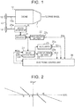
- a first embodiment in which the invention is applied to a vehicle including a hybrid system will be described. First, the schematic configuration of the hybrid system of the first embodiment will be described.
- the hybrid system includes an engine 10 as a driving source of the vehicle.
- a crankshaft 10a of the engine 10 is coupled to a drive wheel via a transmission 11 and other devices so as to drive the drive wheel.
- the crankshaft 10a of the engine 10 is also coupled to a first pulley 12 so as to drive the first pulley 12.
- a transmission belt 13 is wound around the first pulley 12.
- the crankshaft 10a of the engine 10 is further coupled to a hydraulic pump for generating hydraulic pressure, a compressor of an air conditioner, and other devices via a belt, a pulley, a gear (sprocket), a chain , or other components so as to drive the hydraulic pump, the compressor, and other devices.
- the hybrid system includes a motor generator 20 as a driving source other than the engine 10.
- the motor generator 20 is a so-called three-phase alternating-current motor.
- An output shaft 20a of the motor generator 20 is coupled to a second pulley 14 so as to drive the second pulley 14.
- the transmission belt 13 is wound around the second pulley 14. That is, the motor generator 20 is coupled to the crankshaft 10a of the engine 10 via the second pulley 14, the transmission belt 13, and the first pulley 12 so as to drive the crankshaft 10a.
- the motor generator 20 When the motor generator 20 operates as an electric motor, the motor generator 20 supplies torque to the second pulley 14. The torque is input to the crankshaft 10a of the engine 10 via the transmission belt 13 and the first pulley 12. That is, in this case, the motor generator 20 assists the engine 10. On the other hand, when the motor generator 20 operates as a generator, the torque of the crankshaft 10a of the engine 10 is input to the output shaft 20a of the motor generator 20 via the first pulley 12, the transmission belt 13, and the second pulley 14. The motor generator 20 generates electric power commensurate with the rotation of the output shaft 20a.
- a high-voltage battery 22 is connected to the motor generator 20 via an inverter 21.
- the inverter 21 is a so-called bidirectional inverter.
- the inverter 21 converts alternating-current voltage generated by the motor generator 20 to direct-current voltage and outputs the direct-current voltage to the high-voltage battery 22.
- the inverter 21 also converts direct-current voltage output from the high-voltage battery 22 to alternating-current voltage and outputs the alternating-current voltage to the motor generator 20.
- the inverter 21 is shown separately from the motor generator 20; however, the inverter 21 can be incorporated inside a housing of the motor generator 20.
- the high-voltage battery 22 is a lithium ion battery.
- the high-voltage battery 22 supplies electric power to the motor generator 20.
- the motor generator 20 operates as a generator, the high-voltage battery 22 is charged with electric power supplied from the motor generator 20.
- a sensor unit 22a is incorporated in the high-voltage battery 22.
- the sensor unit 22a detects the status of the high-voltage battery 22.
- the sensor unit 22a detects the voltage between the terminals, input current, temperature, and the like, of the high-voltage battery 22, and outputs these detection results as a signal that represents status information SHb about the high-voltage battery 22.
- a DC-DC converter 23 is connected to the motor generator 20 via the inverter 21.
- the DC-DC converter 23 is also connected to the high-voltage battery 22.
- the DC-DC converter 23 steps down direct-current voltage that is output from the inverter 21 or the high-voltage battery 22, to a voltage of 10 V to 15 V, and outputs the stepped-down direct-current voltage.
- a sensor unit 23a is incorporated in the DC-DC converter 23.
- the sensor unit 23a detects the status of the DC-DC converter 23.
- the sensor unit 23a detects the output voltage, output current, and the like, of the DC-DC converter 23, and outputs these detection results as a signal that represents status information Sdc about the DC-DC converter 23.
- a low-voltage battery 24 is connected to the DC-DC converter 23.
- the low-voltage battery 24 is a 12 V lead storage battery lower in voltage than the high-voltage battery 22.
- the low-voltage battery 24 outputs a direct-current voltage of 12 V.
- the output voltage of the DC-DC converter 23 is higher than the open circuit voltage (OCV) of the low-voltage battery 24, the low-voltage battery 24 is charged with electric power supplied from the DC-DC converter 23. That is, the DC-DC converter 23 operates as an electric power supply device for the low-voltage battery 24.
- a sensor unit 24a is incorporated in the low-voltage battery 24.
- the sensor unit 24a detects the status of the low-voltage battery 24.
- the sensor unit 24a detects the voltage between the terminals, input current, temperature, and the like, of the low-voltage battery 24, and outputs these detection results as a signal that represents status information SLb about the low-voltage battery 24.
- auxiliaries 25 are connected to the DC-DC converter 23 and the low-voltage battery 24 as electrically-powered devices.
- the auxiliaries 25 include lighting equipment, such as headlamps, direction indicator lamps and room lamp of the vehicle, and vehicle interior equipment, such as a car navigation system and speakers.
- the auxiliaries 25 are supplied with electric power from the low-voltage battery 24.
- the auxiliaries 25 are supplied with electric power from the DC-DC converter 23. That is, the DC-DC converter 23 operates as an electric power supply device for the auxiliaries 25.
- a sensor unit 25a is incorporated in each of the auxiliaries 25, and detects the status of a corresponding one of the auxiliaries 25.
- Each of the sensor units 25a detects the voltage between the terminals, input current, temperature, and the like, of a corresponding one of the auxiliaries 25, and outputs these detection results as a signal that represents status information SAcc about the corresponding one of the auxiliaries 25.
- the hybrid system includes an electronic control unit 30.
- the electronic control unit 30 generally controls the entire operation of the hybrid system, including charge and discharge of the low-voltage battery 24. That is, a charge-discharge control system includes the electronic control unit 30.
- the electronic control unit 30 is a processing circuit (computer) including an operation unit, a nonvolatile storage unit, a volatile memory, and other components.
- the operation unit executes various programs (applications). Programs, and the like, are stored in the nonvolatile storage unit. Data are temporarily stored in the volatile memory when the programs are executed.
- the signal that represents the status information Sdc is input from the sensor unit 23a of the DC-DC converter 23 to the electronic control unit 30. Based on this signal, the electronic control unit 30 learns the output voltage Vout, output current, and the like, of the DC-DC converter 23.
- the signal that represents the status information SAcc is input from the sensor unit 25a of each of the auxiliaries 25 to the electronic control unit 30. Based on these signals, the electronic control unit 30 calculates the sum of currents that are input to the auxiliaries 25 as an input current Iacc to the auxiliaries 25.
- the signal that represents the status information SLb is input from the sensor unit 24a of the low-voltage battery 24 to the electronic control unit 30.
- the electronic control unit 30 calculates a full charge capacity SOCmax and state of charge SOC of the low-voltage battery 24 based on the information, such as the voltage between the terminals, input current, and temperature, of the low-voltage battery 24, included in the status information SLb.
- the full charge capacity SOCmax of the low-voltage battery 24 is a maximum amount of charge to which the low-voltage battery 24 is allowed to be charged at the time when the status information SLb is input, and is represented by, for example, ampere hour (Ah).
- the state of charge SOC is the proportion of an amount of charge in the low-voltage battery 24 at the time when the status information SLb is input to the full charge capacity SOCmax of the low-voltage battery 24, and is represented by, for example, percentage (%).
- the electronic control unit 30 is configured to calculate the full charge capacity SOCmax of the low-voltage battery 24.
- the electronic control unit 30 is configured to calculate an excess or shortage of the state of charge SOC, calculated as described above, of the low-voltage battery 24 to a target state of charge SOCtg as a state-of-charge difference ⁇ SOC.
- the target state of charge SOCtg is stored in advance in the storage unit of the electronic control unit 30, and is determined within, for example, the range of 80% to 90%.
- the signal that represents the status information SLb is input from the sensor unit 22a of the high-voltage battery 22 to the electronic control unit 30.
- the electronic control unit 30 is configured to adjust the output voltage Vout of the DC-DC converter 23 based on the state-of-charge difference ⁇ SOC calculated as described above.
- a voltage control map (relational expression) is stored in the storage unit of the electronic control unit 30.
- the voltage control map is used to adjust the output voltage Vout of the DC-DC converter 23.
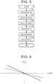
- FIG. 2 in this voltage control map, the relationship between a state-of-charge difference ⁇ SOC and an amount of change ⁇ Vout in the output voltage Vout of the DC-DC converter 23 per unit time (per control period) is set.
- the amount of change ⁇ Vout in output voltage Vout is zero.
- the state-of-charge difference ⁇ SOC is smaller than -A, in other words, when a shortage of the state of charge SOC is larger than A that is a first prescribed value, the amount of change ⁇ Vout in the output voltage Vout is a positive value. As the shortage increases (as the state-of-charge difference ⁇ SOC shifts leftward in FIG. 2 ), the amount of change ⁇ Vout in the output voltage Vout increases.
- the state-of-charge difference ⁇ SOC is larger than +A, in other words, when an excess of the state of charge SOC is larger than A that is a second prescribed value, the amount of change ⁇ Vout in the output voltage Vout is a negative value.
- the charge-discharge control process is repeatedly executed at intervals of a predetermined control period from when an ignition switch (which may also be referred to as system start-up switch, a start switch, or the like) for the engine is turned on to activate the hybrid system to when the hybrid system is deactivated.
- an ignition switch which may also be referred to as system start-up switch, a start switch, or the like
- step S11 the electronic control unit 30 calculates the input current Iacc to the auxiliaries 25 based on the pieces of status information SAcc about the auxiliaries 25. After that, the process of the electronic control unit 30 proceeds to step S12.
- step S12 the electronic control unit 30 calculates the full charge capacity SOCmax of the low-voltage battery 24 based on the status information SLb about the low-voltage battery 24. Specifically, the electronic control unit 30 calculates the full charge capacity SOCmax such that the full charge capacity SOCmax reduces as the temperature of the low-voltage battery 24 decreases. The electronic control unit 30 calculates the full charge capacity SOCmax such that the full charge capacity SOCmax reduces as an integrated value of charge current and discharge current from when the low-voltage battery 24 has been manufactured increases. After the electronic control unit 30 calculates the full charge capacity SOCmax, the process of the electronic control unit 30 proceeds to step S13.
- step S13 the electronic control unit 30 calculates the state of charge SOC of the low-voltage battery 24 based on the status information SLb about the low-voltage battery 24. Specifically, the electronic control unit 30 calculates the state of charge SOC to the full charge capacity SOCmax calculated in step S12 based on an integrated value of charge current of the low-voltage battery 24 and an integrated value of discharge current of the low-voltage battery 24. After that, the process of the electronic control unit 30 proceeds to step S14.
- step S14 the electronic control unit 30 calculates the state-of-charge difference ⁇ SOC by subtracting the target state of charge SOCtg from the state of charge SOC calculated in step S13. Therefore, in this embodiment, a shortage of the state of charge SOC to the target state of charge SOCtg is calculated as a negative state-of-charge difference ⁇ SOC, and an excess of the state of charge SOC to the target state of charge SOCtg is calculated as a positive state-of-charge difference ⁇ SOC. After calculation of the state-of-charge difference ⁇ SOC, the process of the electronic control unit 30 proceeds to step S15.
- the electronic control unit 30 calculates a coefficient ⁇ 1 and a coefficient ⁇ 2 for calculating the amount of change ⁇ Vout in the output voltage Vout of the DC-DC converter 23.
- the coefficient ⁇ 1 and the coefficient ⁇ 2 each are a positive value smaller than or equal to one.
- the electronic control unit 30 calculates the coefficient ⁇ 1 such that the coefficient ⁇ 1 reduces as the input current Iacc to the auxiliaries 25 , calculated in step S11, increases.
- the electronic control unit 30 calculates the coefficient ⁇ 2 such that the coefficient ⁇ 2 reduces as the full charge capacity SOCmax of the low-voltage battery 24, calculated in step S12, reduces.
- a coefficient ⁇ 1 and a coefficient ⁇ 2 each are a value larger than or equal to one.
- the electronic control unit 30 calculates the coefficient ⁇ 1 such that the coefficient ⁇ 1 increases as the input current Iacc to the auxiliaries 25, calculated in step S11, increases.
- the electronic control unit 30 calculates the coefficient ⁇ 2 such that the coefficient ⁇ 2 increases as the full charge capacity SOCmax of the low-voltage battery 24, calculated in step S12, reduces. After these coefficients are calculated, the process of the electronic control unit 30 proceeds to step S16.
- step S16 the electronic control unit 30 calculates the amount of change ⁇ Vout in the output voltage Vout of the DC-DC converter 23 based on the voltage control map (see FIG. 2 ) stored in the storage unit and the coefficient ⁇ 1 , the coefficient ⁇ 2, the coefficient ⁇ 1, and the coefficient ⁇ 2, calculated in step S15.
- the electronic control unit 30 multiplies the rate of change (the slope of the straight line in FIG. 2 ) in the amount of change ⁇ Vout to the state-of-charge difference ⁇ SOC in the voltage control map by the coefficient ⁇ 1 and the coefficient ⁇ 2.
- the coefficient ⁇ 1 and the coefficient ⁇ 2 each are a positive value smaller than or equal to one. Therefore, the rate of change in the amount of change ⁇ Vout, newly calculated in step S16, to the state-of-charge difference ⁇ SOC is smaller than the rate of change in the voltage control map stored in the storage unit (the slope of the straight line becomes gentler).
- the electronic control unit 30 calculates a new first prescribed value B (second prescribed value B) by multiplying the first prescribed value A (second prescribed value A) in the voltage control map by the coefficient ⁇ 1 and the coefficient ⁇ 2.
- the coefficient ⁇ 1 and the coefficient ⁇ 2 each are a value larger than or equal to one. Therefore, the first prescribed value B that is newly calculated in step S16 is larger than the first prescribed value A in the voltage control map. In this way, a map (relational expression) between a state-of-charge difference ⁇ SOC and an amount of change ⁇ Vout is newly calculated.
- the electronic control unit 30 calculates the amount of change ⁇ Vout in the output voltage Vout by substituting the state-of-charge difference ⁇ SOC calculated in step S14 into the calculated map (relational expression). After that, the process of the electronic control unit 30 proceeds to step S17.
- step S17 the electronic control unit 30 calculates a new target voltage Vn of the output voltage Vout of the DC-DC converter 23 by adding the amount of change ⁇ Vout calculated in step S16 to a target voltage Vn-1 calculated in the last control cycle.
- the last target voltage Vn-1 is treated as a predetermined initial value (for example, the open circuit voltage of the low-voltage battery 24).
- the electronic control unit 30 outputs an operation signal MSdc commensurate with the calculated target voltage Vn to the DC-DC converter 23.
- step S11 is executed again after a predetermined control period.
- the state of charge SOC of the low-voltage battery 24 is lower than the target state of charge SOCtg and a shortage of the state of charge SOC is larger than the first prescribed value A. That is, it is assumed that, in the graph shown in FIG. 2 , the state-of-charge difference ⁇ SOC is smaller than -A. In this case, the amount of change ⁇ Vout is calculated as a positive value. Therefore, before the difference between the state of charge SOC of the low-voltage battery 24 and the target state of charge SOCtg becomes smaller than or equal to the first prescribed value A, the output voltage Vout (target voltage Vn) of the DC-DC converter 23 continues to increase.
- the output voltage Vout of the DC-DC converter 23 starts decreasing. Then, as the output voltage Vout of the DC-DC converter 23 becomes lower than the open circuit voltage of the low-voltage battery 24, the low-voltage battery 24 starts discharging electric power, and the state of charge SOC of the low-voltage battery 24 starts decreasing.
- the rate of change in the amount of change ⁇ Vout to the state-of-charge difference ⁇ SOC decreases as represented by the alternate long and short dashes line in FIG. 2 , with the result that the amount of change ⁇ Vout in the output voltage Vout of the DC-DC converter 23 per unit time reduces. Therefore, the amount of increase in the output voltage Vout of the DC-DC converter 23 from when the state of charge SOC of the low-voltage battery 24 is low to when the state of charge SOC reaches the target state of charge SOCtg is reduced as compared to the above-described example.
- the rate of change in the amount of change ⁇ Vout to the state-of-charge difference ⁇ SOC decreases as represented by the alternate long and short dashes line in FIG. 2 , so the amount of change ⁇ Vout in the output voltage Vout of the DC-DC converter 23 per unit time reduces. Therefore, the amount of increase in the output voltage Vout of the DC-DC converter 23 from when the state of charge SOC of the low-voltage battery 24 is low to when the state of charge SOC reaches the target state of charge SOCtg is reduced.
- the first prescribed value A is replaced with the larger first prescribed value B as shown in FIG. 2 . Therefore, the amount of change ⁇ Vout in the output voltage Vout of the DC-DC converter 23 becomes zero in an early stage before the state of charge SOC of the low-voltage battery 24 reaches the target state of charge SOCtg, and the output voltage Vout of the DC-DC converter 23 becomes constant. For this reason, the output voltage Vout of the DC-DC converter 23 at the time when the state of charge SOC of the low-voltage battery 24 has reached the target state of charge SOCtg is decreased to a lower voltage.
- a second embodiment in which the invention is applied to a vehicle including a hybrid system will be described.
- the schematic configuration of the hybrid system in the second embodiment is similar to that of the first embodiment (see FIG. 1 ), so the description of overlapping portions will be simplified or omitted.
- the electronic control unit 30 in the hybrid system of the second embodiment is configured to calculate an excess or shortage to the target state of charge SOCtg as a state-of-charge difference ⁇ SOC and adjust the output voltage Vout of the DC-DC converter 23.
- the electronic control unit 30 is configured to calculate a battery input current Ibat to the low-voltage battery 24 based on the status information SLb that is input from the sensor unit 24a of the low-voltage battery 24.
- the electronic control unit 30 is configured to set a target input current Itg of the battery input current Ibat to the low-voltage battery 24 based on the state-of-charge difference ⁇ SOC.
- a voltage control map (relational expression) that is used to adjust the output voltage Vout of the DC-DC converter 23 is stored in the storage unit of the electronic control unit 30.
- this voltage control map the relationship between a state-of-charge difference ⁇ SOC and a target input current Itg to the low-voltage battery 24 is set. Specifically, as represented by the solid line in FIG. 4 , within the range in which the state-of-charge difference ⁇ SOC is larger than or equal to -C and smaller than or equal to +C, the target input current Itg is zero.
- the target input current Itg is a positive value.
- the target input current Itg increases.
- the state-of-charge difference ⁇ SOC is larger than +C, in other words, when an excess of the state of charge SOC is larger than C that is a second prescribed value, the target input current Itg is a negative value.
- the target input current Itg reduces.
- the charge-discharge control process is repeatedly executed at intervals of a predetermined control period from when the ignition switch for the engine is turned on to activate the hybrid system to when the hybrid system is deactivated.
- step S21 the electronic control unit 30 calculates the battery input current Ibat to the low-voltage battery 24 based on the status information SLb about the low-voltage battery 24. After that, the process of the electronic control unit 30 proceeds to step S22.
- step S22 the electronic control unit 30 calculates the state of charge SOC of the low-voltage battery 24 based on the status information SLb about the low-voltage battery 24. Specifically, the electronic control unit 30 calculates the full charge capacity SOCmax based on the temperature of the low-voltage battery 24, and an integrated value of charge current and discharge current from when the low-voltage battery 24 is manufactured. The electronic control unit 30 calculates the state of charge SOC to the full charge capacity SOCmax based on the integrated value of charge current to the low-voltage battery 24 and the integrated value of discharge current from the low-voltage battery 24. After that, the process of the electronic control unit 30 proceeds to step S23.
- step S23 the electronic control unit 30 calculates the state-of-charge difference ⁇ SOC by subtracting the target state of charge SOCtg from the state of charge SOC calculated in step S22. Therefore, in this embodiment, a shortage of the state of charge SOC to the target state of charge SOCtg is calculated as a negative state-of-charge difference ⁇ SOC, and an excess of the state of charge SOC to the target state of charge SOCtg is calculated as a positive state-of-charge difference ⁇ SOC. After calculation of the state-of-charge difference ⁇ SOC, the process of the electronic control unit 30 proceeds to step S24.
- step S24 the electronic control unit 30 calculates the target input current Itg by substituting the state-of-charge difference ⁇ SOC calculated in step S23 into the voltage control map (see FIG. 4 ) stored in the storage unit. Therefore, the target input current Itg is calculated as a positive value when the state-of-charge difference ⁇ SOC is smaller than -C, and the target input current Itg is calculated as zero when the state-of-charge difference ⁇ SOC is larger than or equal to -C and smaller than or equal to C. When the state-of-charge difference ⁇ SOC is larger than C, the target input current Itg is calculated as a negative value. After the target input current Itg is calculated, the process of the electronic control unit 30 proceeds to step S25.
- step S25 the electronic control unit 30 calculates the amount of change ⁇ Vout in the output voltage Vout of the DC-DC converter 23 based on the battery input current Ibat calculated in step S21 and the target input current Itg calculated in step S24. Specifically, the electronic control unit 30 subtracts the battery input current Ibat from the target input current Itg. The electronic control unit 30 calculates the amount of change ⁇ Vout in the output voltage Vout by multiplying the subtracted value by a predetermined coefficient K.
- the coefficient K is determined based on an internal resistance, or the like, of the low-voltage battery 24, and is calculated in advance by testing, or the like.
- step S26 the electronic control unit 30 calculates a new target voltage Vn of the output voltage Vout of the DC-DC converter 23 by adding the amount of change ⁇ Vout calculated in step S25 to the target voltage Vn-1 calculated in the last control cycle.
- the last target voltage Vn-1 is treated as a predetermined initial value (for example, the open circuit voltage of the low-voltage battery 24).
- the electronic control unit 30 outputs an operation signal MSdc commensurate with the calculated target voltage Vn to the DC-DC converter 23.
- step S21 is executed again after a predetermined control period.
- the full charge capacity SOCmax of the low-voltage battery 24 in the hybrid system is property large such that various auxiliaries 25 are allowed to be driven over a certain period of time without electric power supplied from the DC-DC converter 23. Therefore, even when the low-voltage battery 24 is charged in the case where the state of charge SOC of the low-voltage battery 24 is lower than the target state of charge SOCtg, it takes several minutes to several tens of minutes until the state of charge SOC reaches the target state of charge SOCtg.
- the output voltage Vout of the DC-DC converter 23 is increased on the condition that the state of charge SOC is lower than the target state of charge SOCtg, the output voltage Vout may be excessively high at the time when the state of charge SOC has reached the target state of charge SOCtg.
- the output voltage Vout of the DC-DC converter 23 at the time when the state of charge SOC has reached the target state of charge SOCtg is excessively high, unignorable hunting for the discharge voltage of the low-voltage battery 24 or the output voltage Vout of the DC-DC converter 23 easily occurs when the low-voltage battery 24 starts discharging electric power.
- the target input current Itg to the low-voltage battery 24 is calculated commensurately with the difference between the state of charge SOC of the low-voltage battery 24 and the target state of charge SOCtg.
- the target input current Itg to the low-voltage battery 24 is calculated as a larger value, so the rate of charge of the low-voltage battery 24 becomes faster. In this way, appropriate charge and discharge commensurate with the difference between the state of charge SOC of the low-voltage battery 24 and the target state of charge SOCtg is ensured.
- the amount of change ⁇ Vout in the output voltage Vout of the DC-DC converter 23 is calculated commensurately with the difference between the battery input current Ibat to the low-voltage battery 24 and the target input current Itg.
- the output voltage Vout of the DC-DC converter 23 varies, the battery input current Ibat to the low-voltage battery 24 almost immediately keeps track of the output voltage Vout. For this reason, a continuous increase or continuous decrease in the output voltage Vout of the DC-DC converter 23 due to the long-term difference between the battery input current Ibat and the target input current Itg is avoided.
- the state of charge SOC of the low-voltage battery 24 has reached the target state of charge SOCtg, an excessive increase or decrease in the output voltage Vout of the DC-DC converter 23 is avoided.
- the battery input current Ibat to the low-voltage battery 24 is adjusted to zero (the target input current Itg is zero). That is, within the range in which the state-of-charge difference ⁇ SOC is larger than or equal to -C and smaller than or equal to C, the output voltage Vout of the DC-DC converter 23 is the voltage at which the low-voltage battery 24 is not charged or discharged, that is, the voltage that is not excessively high or excessively low.
- the embodiments may be modified as follows.
- the embodiments and the following alternative embodiments may be implemented in combination with each other if there is technically no conflict.
- the electronic control unit 30 that generally controls the entire operation of the hybrid system executes a series of steps in the charge-discharge control process.
- a controller that controls the engine 10 and a controller that executes the charge-discharge control process may be separate processing circuits (computers).
- the value of the output voltage of the low-voltage battery 24 that is subjected to the charge-discharge control process of each of the embodiments does not matter.
- the output voltage of the low-voltage battery 24 does not always need to be lower than the output voltage of the high-voltage battery 22.
- the output voltage of the low-voltage battery 24 and the output voltage of the high-voltage battery 22 may be the same.
- the type of the low-voltage battery 24 that is subjected to the charge-discharge control process of each of the embodiments is not limited to the examples of the embodiments.
- a lithium ion battery, a nickel-metal hydride battery, a NAS battery, an all-solid battery, or the like may be employed as the low-voltage battery 24. That is, the low-voltage battery 24 just needs to be a secondary battery that is repeatedly chargeable.
- the charge-discharge control process of each of the embodiments may be applied to charge-discharge control over the high-voltage battery 22 instead of or in addition to charge-discharge control over the low-voltage battery 24.
- the motor generator 20 may be regarded as an electric power supply device for the high-voltage battery 22.
- the DC-DC converter 23 is a bidirectional converter that is able to step up and output the voltage of the low-voltage battery 24, the DC-DC converter 23 may also be regarded as an electric power supply device for the high-voltage battery 22.
- the charge-discharge control process of each of the embodiments is not limited to application to charge-discharge control over a battery of a hybrid system.
- the charge-discharge control process of each of the embodiments may be applied to a drive system as follows.
- the motor generator 20 and the high-voltage battery 22 are omitted, an alternator that generates electric power by using the driving force of the engine 10 is provided, and electric power is supplied from the alternator to the DC-DC converter 23 via the inverter 21.
- the alternator does not assist the engine 10, and only the engine 10 operates as a driving source of the vehicle.
- the sensor unit 23a is incorporated in the DC-DC converter 23; however, the disposition of the sensor unit 23a is not limited thereto.
- the sensor unit 23a may be connected to the wire between the DC-DC converter 23 and the low-voltage battery 24. This also applies to each of the sensor units of the high-voltage battery 22, low-voltage battery 24, and auxiliaries 25.
- the amount of change ⁇ Vout in the output voltage Vout of the DC-DC converter 23 varies with the input current Iacc to the auxiliaries 25 and the full charge capacity SOCmax of the low-voltage battery 24. Instead, the amount of change ⁇ Vout may vary only with the full charge capacity SOCmax.
- the first prescribed value A (-A in FIG. 2 ) and the second prescribed value A (+A in FIG. 2 ) in the voltage control map varies with the input current Iacc to the auxiliaries 25 and the full charge capacity SOCmax of the low-voltage battery 24.
- these values may be fixed values.
- the amount of change ⁇ Vout just needs to be a positive value when the state-of-charge difference ⁇ SOC is lower than -A, and, for example, the amount of change ⁇ Vout may be a positive fixed value. Similarly, when the state-of-charge difference ⁇ SOC is higher than +A, the amount of change ⁇ Vout may be a negative fixed value.
- the first prescribed value and the second prescribed value each are A.
- the first prescribed value and the second prescribed value may be different values.
- the minimum value of each of the first prescribed value and the second prescribed value may be set to zero.
- the relationship between a state-of-charge difference ⁇ SOC and an amount of change ⁇ Vout is a relationship that the origin at which the state-of-charge difference ⁇ SOC is zero and the amount of change ⁇ Vout is zero is passed and the amount of change ⁇ Vout reduces as the state-of-charge difference ⁇ SOC increases.
- the first prescribed value and the second prescribed value each are desirably a large value.
- the first prescribed value and the second prescribed value each are a large value, there are increased situations in which the output voltage Vout of the DC-DC converter 23 does not vary with the state-of-charge difference ⁇ SOC, so a period of time that is taken until the state of charge SOC of the low-voltage battery 24 reaches the target state of charge SOCtg may extend.
- the first prescribed value and the second prescribed value each may be fixed at zero.
- only the rate of change (the slope of the line) in the amount of change ⁇ Vout to the state-of-charge difference ⁇ SOC in the voltage control map varies with the input current Iacc to the auxiliaries 25 and the full charge capacity SOCmax of the low-voltage battery 24.
- the amount of change ⁇ Vout in the output voltage Vout of the DC-DC converter 23 is calculated by using the coefficient ⁇ 1, the coefficient ⁇ 2, the coefficient ⁇ 1, and the coefficient ⁇ 2; however, calculation of the amount of change ⁇ Vout is not limited thereto.
- a charge-discharge control map may be prepared for each of the different full charge capacities SOCmax and each of the different input currents Iacc, and the amount of change ⁇ Vout may be calculated based on the map of which the closest full charge capacity SOCmax and the closest input current Iacc among the plurality of charge-discharge control maps.
- step S16 The order of the steps of the charge-discharge control process in the first embodiment is illustrative, and may be modified as needed.
- step S11 to step S15 the order of the processes of step S11 to step S15 does not matter, and part of the steps may be processed in parallel. This also applies to the charge-discharge control process in the second embodiment, and parameters required to calculate the amount of change ⁇ Vout just needs to be calculated in step S25.
- the relationship between a state-of-charge difference ⁇ SOC and a target input current Itg may be linear. That is, the first prescribed value and the second prescribed value each may be zero. In addition, the first prescribed value and the second prescribed value each may vary commensurately with, for example, the full charge capacity SOCmax of the low-voltage battery 24 or the input current Iacc to the auxiliaries 25 or both.
Landscapes
- Engineering & Computer Science (AREA)
- Mechanical Engineering (AREA)
- Transportation (AREA)
- Power Engineering (AREA)
- Sustainable Energy (AREA)
- Life Sciences & Earth Sciences (AREA)
- Sustainable Development (AREA)
- Chemical & Material Sciences (AREA)
- Combustion & Propulsion (AREA)
- Physics & Mathematics (AREA)
- General Physics & Mathematics (AREA)
- Automation & Control Theory (AREA)
- Manufacturing & Machinery (AREA)
- Chemical Kinetics & Catalysis (AREA)
- Electrochemistry (AREA)
- General Chemical & Material Sciences (AREA)
- Charge And Discharge Circuits For Batteries Or The Like (AREA)
- Electric Propulsion And Braking For Vehicles (AREA)
- Secondary Cells (AREA)
- Auxiliary Drives, Propulsion Controls, And Safety Devices (AREA)
Applications Claiming Priority (1)
| Application Number | Priority Date | Filing Date | Title |
|---|---|---|---|
| JP2018071357A JP7059761B2 (ja) | 2018-04-03 | 2018-04-03 | 車両の充放電制御装置 |
Publications (2)
| Publication Number | Publication Date |
|---|---|
| EP3549809A1 true EP3549809A1 (fr) | 2019-10-09 |
| EP3549809B1 EP3549809B1 (fr) | 2021-07-28 |
Family
ID=66091886
Family Applications (1)
| Application Number | Title | Priority Date | Filing Date |
|---|---|---|---|
| EP19166690.8A Active EP3549809B1 (fr) | 2018-04-03 | 2019-04-02 | Système de commande de charge-décharge pour véhicule |
Country Status (4)
| Country | Link |
|---|---|
| US (1) | US11221369B2 (fr) |
| EP (1) | EP3549809B1 (fr) |
| JP (1) | JP7059761B2 (fr) |
| CN (1) | CN110350612B (fr) |
Cited By (3)
| Publication number | Priority date | Publication date | Assignee | Title |
|---|---|---|---|---|
| CN111055725A (zh) * | 2019-11-29 | 2020-04-24 | 深圳猛犸电动科技有限公司 | 电动车电池老化识别方法、装置、终端设备及存储介质 |
| CN112543717A (zh) * | 2020-09-08 | 2021-03-23 | 华为技术有限公司 | 低压蓄电池充电系统及方法 |
| FR3104082A1 (fr) * | 2019-12-05 | 2021-06-11 | Psa Automobiles Sa | Procede de gestion de l’etat de charge d’une batterie lithium-ion pour vehicule comportant un moteur electrique et un convertisseur de tension continu-continu |
Families Citing this family (11)
| Publication number | Priority date | Publication date | Assignee | Title |
|---|---|---|---|---|
| JP6710239B2 (ja) * | 2018-05-25 | 2020-06-17 | 本田技研工業株式会社 | 車両の電源システム |
| DE102019218489A1 (de) * | 2019-11-28 | 2021-06-02 | Robert Bosch Gmbh | Verfahren und Vorrichtung zum Laden einer Batterie für ein Fortbewegungsmittel |
| CN111525631B (zh) * | 2020-03-18 | 2023-11-10 | 武汉路特斯汽车有限公司 | 一种锂电池的能量管理方法、装置、电子设备及存储介质 |
| JP7074791B2 (ja) * | 2020-03-31 | 2022-05-24 | 本田技研工業株式会社 | 車載システム、二次電池管理システム、充電率の出力方法、およびプログラム |
| US11760223B2 (en) * | 2020-06-23 | 2023-09-19 | Toyota Motor North America, Inc. | Need-based energy sharing |
| US11345251B2 (en) | 2020-06-23 | 2022-05-31 | Toyota Motor North America, Inc. | Priority-based energy transfer |
| KR102414493B1 (ko) * | 2020-09-24 | 2022-07-01 | 한국전력공사 | 전기이동체를 위한 충방전 제어 방법 및 이를 수행하는 충방전 시스템 |
| JP7526065B2 (ja) * | 2020-09-28 | 2024-07-31 | 株式会社Subaru | 車両 |
| JP7564670B2 (ja) * | 2020-09-28 | 2024-10-09 | 株式会社Subaru | 車両 |
| CN112736311B (zh) * | 2021-01-08 | 2022-07-19 | 恒大新能源汽车投资控股集团有限公司 | 蓄电池的充电方法、装置和电子设备 |
| FR3122367A1 (fr) * | 2021-04-30 | 2022-11-04 | Psa Automobiles Sa | Gestion stratégique d’un groupe d’alimentation électrique d’un véhicule en fonction d’informations concernant la batterie de servitude |
Citations (5)
| Publication number | Priority date | Publication date | Assignee | Title |
|---|---|---|---|---|
| US20110066331A1 (en) * | 2008-05-12 | 2011-03-17 | Toyota Jidosha Kabushiki Kaisha | Steering device for vehicle and control method for steering device |
| EP2453546A1 (fr) * | 2010-11-12 | 2012-05-16 | Fiat Powertrain Technologies S.p.A. | Système électrique automobile fourni avec un système de contrôle électronique d'alternateur |
| US8256547B2 (en) * | 2007-02-20 | 2012-09-04 | Toyota Jidosha Kabushiki Kaisha | Hybrid vehicle |
| JP2013193618A (ja) | 2012-03-21 | 2013-09-30 | Toyota Motor Corp | 車両用制御装置、及び発電制御方法 |
| US20160114690A1 (en) * | 2014-10-27 | 2016-04-28 | Toyota Jidosha Kabushiki Kaisha | External power supply of fuel cell mounted vehicle and control method therefor |
Family Cites Families (12)
| Publication number | Priority date | Publication date | Assignee | Title |
|---|---|---|---|---|
| JP3028867B2 (ja) | 1991-07-31 | 2000-04-04 | 富士重工業株式会社 | オルタネータの発電制御装置 |
| JP3094772B2 (ja) * | 1994-02-21 | 2000-10-03 | トヨタ自動車株式会社 | 発電機を搭載する電気自動車の発電機出力制御装置 |
| JP3772730B2 (ja) * | 2001-11-02 | 2006-05-10 | 日産自動車株式会社 | 車両用バッテリの劣化診断装置 |
| JP5035978B2 (ja) * | 2007-08-24 | 2012-09-26 | 株式会社日本自動車部品総合研究所 | 車両用dcdcコンバータ装置 |
| JP2009213335A (ja) | 2008-03-06 | 2009-09-17 | Nissan Motor Co Ltd | 発電機制御装置 |
| JP4466772B2 (ja) * | 2008-09-03 | 2010-05-26 | トヨタ自動車株式会社 | 車両の制御装置 |
| JP2010183758A (ja) * | 2009-02-06 | 2010-08-19 | Nissan Motor Co Ltd | 車両用制御装置 |
| JP2011072067A (ja) * | 2009-09-24 | 2011-04-07 | Toyota Motor Corp | 車両の電源システムおよびそれを備える電動車両 |
| US20140021919A1 (en) * | 2011-03-28 | 2014-01-23 | Toyota Jidosha Kabushiki Kaisha | Electrically powered vehicle and method for controlling same |
| JP6190185B2 (ja) * | 2013-07-03 | 2017-08-30 | 川崎重工業株式会社 | マイクログリッドの制御装置及びその制御方法 |
| JP6507625B2 (ja) * | 2014-12-19 | 2019-05-08 | 株式会社デンソー | ハイブリッド車の制御装置 |
| KR101806179B1 (ko) * | 2016-06-02 | 2017-12-07 | 현대자동차 주식회사 | 하이브리드 차량의 토크 저감 제어 방법 |
-
2018
- 2018-04-03 JP JP2018071357A patent/JP7059761B2/ja active Active
-
2019
- 2019-03-28 US US16/367,625 patent/US11221369B2/en active Active
- 2019-04-01 CN CN201910256623.8A patent/CN110350612B/zh active Active
- 2019-04-02 EP EP19166690.8A patent/EP3549809B1/fr active Active
Patent Citations (5)
| Publication number | Priority date | Publication date | Assignee | Title |
|---|---|---|---|---|
| US8256547B2 (en) * | 2007-02-20 | 2012-09-04 | Toyota Jidosha Kabushiki Kaisha | Hybrid vehicle |
| US20110066331A1 (en) * | 2008-05-12 | 2011-03-17 | Toyota Jidosha Kabushiki Kaisha | Steering device for vehicle and control method for steering device |
| EP2453546A1 (fr) * | 2010-11-12 | 2012-05-16 | Fiat Powertrain Technologies S.p.A. | Système électrique automobile fourni avec un système de contrôle électronique d'alternateur |
| JP2013193618A (ja) | 2012-03-21 | 2013-09-30 | Toyota Motor Corp | 車両用制御装置、及び発電制御方法 |
| US20160114690A1 (en) * | 2014-10-27 | 2016-04-28 | Toyota Jidosha Kabushiki Kaisha | External power supply of fuel cell mounted vehicle and control method therefor |
Cited By (4)
| Publication number | Priority date | Publication date | Assignee | Title |
|---|---|---|---|---|
| CN111055725A (zh) * | 2019-11-29 | 2020-04-24 | 深圳猛犸电动科技有限公司 | 电动车电池老化识别方法、装置、终端设备及存储介质 |
| CN111055725B (zh) * | 2019-11-29 | 2021-03-19 | 深圳猛犸电动科技有限公司 | 电动车电池老化识别方法、装置、终端设备及存储介质 |
| FR3104082A1 (fr) * | 2019-12-05 | 2021-06-11 | Psa Automobiles Sa | Procede de gestion de l’etat de charge d’une batterie lithium-ion pour vehicule comportant un moteur electrique et un convertisseur de tension continu-continu |
| CN112543717A (zh) * | 2020-09-08 | 2021-03-23 | 华为技术有限公司 | 低压蓄电池充电系统及方法 |
Also Published As
| Publication number | Publication date |
|---|---|
| JP2019182009A (ja) | 2019-10-24 |
| EP3549809B1 (fr) | 2021-07-28 |
| US20190302192A1 (en) | 2019-10-03 |
| CN110350612B (zh) | 2023-03-03 |
| JP7059761B2 (ja) | 2022-04-26 |
| US11221369B2 (en) | 2022-01-11 |
| CN110350612A (zh) | 2019-10-18 |
Similar Documents
| Publication | Publication Date | Title |
|---|---|---|
| EP3549809B1 (fr) | Système de commande de charge-décharge pour véhicule | |
| CN109941088B (zh) | 混合动力汽车以及混合动力汽车的控制方法 | |
| JP4773848B2 (ja) | 二次電池の充放電制御システム、電池制御装置、およびプログラム | |
| JP5889750B2 (ja) | 車両用電源システム | |
| US9950629B2 (en) | Vehicle power source | |
| CN110535218B (zh) | 电池放电控制装置 | |
| CN109387790B (zh) | 电源系统 | |
| JP6878782B2 (ja) | 電源制御装置、及び電源システム | |
| CN109383327B (zh) | 电源系统 | |
| JP5501070B2 (ja) | 電源電圧保護装置、及び、電源電圧保護方法 | |
| WO2020017168A1 (fr) | Dispositif de commande d'alimentation et procédé de commande d'alimentation pour véhicule hybride | |
| US20210261018A1 (en) | Vehicle power supply device | |
| JP2016193632A (ja) | 車両用電源装置 | |
| WO2017188163A1 (fr) | Dispositif de commande de source d'alimentation | |
| MX2011004253A (es) | Metodo y dispositivo de control de un sistema micro-hibrido con frenado de recuperacion apto para equipar un vehiculo automotor. | |
| WO2018008567A1 (fr) | Dispositif et système de commande de source d'alimentation | |
| EP3425766A1 (fr) | Module de capaciteur | |
| JP7111044B2 (ja) | 制御装置 | |
| JP2019205276A (ja) | 電源装置 | |
| JP7183922B2 (ja) | 制御装置 | |
| JP6936683B2 (ja) | 車両用電源システム及び車両用電源システムの制御装置 | |
| JP7036081B2 (ja) | 制御装置 | |
| JP7004385B2 (ja) | 管理装置、及び電源システム | |
| WO2016121450A1 (fr) | Dispositif de commande pour alimentation électrique embarquée | |
| JP2023086278A (ja) | 電源システム |
Legal Events
| Date | Code | Title | Description |
|---|---|---|---|
| PUAI | Public reference made under article 153(3) epc to a published international application that has entered the european phase |
Free format text: ORIGINAL CODE: 0009012 |
|
| STAA | Information on the status of an ep patent application or granted ep patent |
Free format text: STATUS: REQUEST FOR EXAMINATION WAS MADE |
|
| 17P | Request for examination filed |
Effective date: 20190429 |
|
| AK | Designated contracting states |
Kind code of ref document: A1 Designated state(s): AL AT BE BG CH CY CZ DE DK EE ES FI FR GB GR HR HU IE IS IT LI LT LU LV MC MK MT NL NO PL PT RO RS SE SI SK SM TR |
|
| AX | Request for extension of the european patent |
Extension state: BA ME |
|
| GRAP | Despatch of communication of intention to grant a patent |
Free format text: ORIGINAL CODE: EPIDOSNIGR1 |
|
| STAA | Information on the status of an ep patent application or granted ep patent |
Free format text: STATUS: GRANT OF PATENT IS INTENDED |
|
| RIC1 | Information provided on ipc code assigned before grant |
Ipc: B60L 58/13 20190101ALI20210209BHEP Ipc: B60W 20/13 20160101ALI20210209BHEP Ipc: H02M 3/155 20060101ALI20210209BHEP Ipc: B60K 6/485 20071001ALI20210209BHEP Ipc: B60W 10/26 20060101ALI20210209BHEP Ipc: B60L 50/16 20190101ALI20210209BHEP Ipc: B60L 58/16 20190101ALI20210209BHEP Ipc: B60W 10/06 20060101ALI20210209BHEP Ipc: B60L 1/00 20060101AFI20210209BHEP Ipc: B60L 58/12 20190101ALI20210209BHEP Ipc: B60W 10/08 20060101ALI20210209BHEP Ipc: B60L 58/20 20190101ALI20210209BHEP |
|
| INTG | Intention to grant announced |
Effective date: 20210224 |
|
| GRAS | Grant fee paid |
Free format text: ORIGINAL CODE: EPIDOSNIGR3 |
|
| GRAA | (expected) grant |
Free format text: ORIGINAL CODE: 0009210 |
|
| STAA | Information on the status of an ep patent application or granted ep patent |
Free format text: STATUS: THE PATENT HAS BEEN GRANTED |
|
| AK | Designated contracting states |
Kind code of ref document: B1 Designated state(s): AL AT BE BG CH CY CZ DE DK EE ES FI FR GB GR HR HU IE IS IT LI LT LU LV MC MK MT NL NO PL PT RO RS SE SI SK SM TR |
|
| REG | Reference to a national code |
Ref country code: GB Ref legal event code: FG4D |
|
| REG | Reference to a national code |
Ref country code: CH Ref legal event code: EP |
|
| REG | Reference to a national code |
Ref country code: DE Ref legal event code: R096 Ref document number: 602019006345 Country of ref document: DE |
|
| REG | Reference to a national code |
Ref country code: AT Ref legal event code: REF Ref document number: 1414439 Country of ref document: AT Kind code of ref document: T Effective date: 20210815 |
|
| REG | Reference to a national code |
Ref country code: IE Ref legal event code: FG4D |
|
| REG | Reference to a national code |
Ref country code: LT Ref legal event code: MG9D |
|
| REG | Reference to a national code |
Ref country code: NL Ref legal event code: MP Effective date: 20210728 |
|
| REG | Reference to a national code |
Ref country code: AT Ref legal event code: MK05 Ref document number: 1414439 Country of ref document: AT Kind code of ref document: T Effective date: 20210728 |
|
| PG25 | Lapsed in a contracting state [announced via postgrant information from national office to epo] |
Ref country code: LT Free format text: LAPSE BECAUSE OF FAILURE TO SUBMIT A TRANSLATION OF THE DESCRIPTION OR TO PAY THE FEE WITHIN THE PRESCRIBED TIME-LIMIT Effective date: 20210728 Ref country code: BG Free format text: LAPSE BECAUSE OF FAILURE TO SUBMIT A TRANSLATION OF THE DESCRIPTION OR TO PAY THE FEE WITHIN THE PRESCRIBED TIME-LIMIT Effective date: 20211028 Ref country code: AT Free format text: LAPSE BECAUSE OF FAILURE TO SUBMIT A TRANSLATION OF THE DESCRIPTION OR TO PAY THE FEE WITHIN THE PRESCRIBED TIME-LIMIT Effective date: 20210728 Ref country code: NL Free format text: LAPSE BECAUSE OF FAILURE TO SUBMIT A TRANSLATION OF THE DESCRIPTION OR TO PAY THE FEE WITHIN THE PRESCRIBED TIME-LIMIT Effective date: 20210728 Ref country code: NO Free format text: LAPSE BECAUSE OF FAILURE TO SUBMIT A TRANSLATION OF THE DESCRIPTION OR TO PAY THE FEE WITHIN THE PRESCRIBED TIME-LIMIT Effective date: 20211028 Ref country code: PT Free format text: LAPSE BECAUSE OF FAILURE TO SUBMIT A TRANSLATION OF THE DESCRIPTION OR TO PAY THE FEE WITHIN THE PRESCRIBED TIME-LIMIT Effective date: 20211129 Ref country code: HR Free format text: LAPSE BECAUSE OF FAILURE TO SUBMIT A TRANSLATION OF THE DESCRIPTION OR TO PAY THE FEE WITHIN THE PRESCRIBED TIME-LIMIT Effective date: 20210728 Ref country code: SE Free format text: LAPSE BECAUSE OF FAILURE TO SUBMIT A TRANSLATION OF THE DESCRIPTION OR TO PAY THE FEE WITHIN THE PRESCRIBED TIME-LIMIT Effective date: 20210728 Ref country code: RS Free format text: LAPSE BECAUSE OF FAILURE TO SUBMIT A TRANSLATION OF THE DESCRIPTION OR TO PAY THE FEE WITHIN THE PRESCRIBED TIME-LIMIT Effective date: 20210728 Ref country code: ES Free format text: LAPSE BECAUSE OF FAILURE TO SUBMIT A TRANSLATION OF THE DESCRIPTION OR TO PAY THE FEE WITHIN THE PRESCRIBED TIME-LIMIT Effective date: 20210728 Ref country code: FI Free format text: LAPSE BECAUSE OF FAILURE TO SUBMIT A TRANSLATION OF THE DESCRIPTION OR TO PAY THE FEE WITHIN THE PRESCRIBED TIME-LIMIT Effective date: 20210728 |
|
| PG25 | Lapsed in a contracting state [announced via postgrant information from national office to epo] |
Ref country code: PL Free format text: LAPSE BECAUSE OF FAILURE TO SUBMIT A TRANSLATION OF THE DESCRIPTION OR TO PAY THE FEE WITHIN THE PRESCRIBED TIME-LIMIT Effective date: 20210728 Ref country code: LV Free format text: LAPSE BECAUSE OF FAILURE TO SUBMIT A TRANSLATION OF THE DESCRIPTION OR TO PAY THE FEE WITHIN THE PRESCRIBED TIME-LIMIT Effective date: 20210728 Ref country code: GR Free format text: LAPSE BECAUSE OF FAILURE TO SUBMIT A TRANSLATION OF THE DESCRIPTION OR TO PAY THE FEE WITHIN THE PRESCRIBED TIME-LIMIT Effective date: 20211029 |
|
| PG25 | Lapsed in a contracting state [announced via postgrant information from national office to epo] |
Ref country code: DK Free format text: LAPSE BECAUSE OF FAILURE TO SUBMIT A TRANSLATION OF THE DESCRIPTION OR TO PAY THE FEE WITHIN THE PRESCRIBED TIME-LIMIT Effective date: 20210728 |
|
| REG | Reference to a national code |
Ref country code: DE Ref legal event code: R097 Ref document number: 602019006345 Country of ref document: DE |
|
| PG25 | Lapsed in a contracting state [announced via postgrant information from national office to epo] |
Ref country code: SM Free format text: LAPSE BECAUSE OF FAILURE TO SUBMIT A TRANSLATION OF THE DESCRIPTION OR TO PAY THE FEE WITHIN THE PRESCRIBED TIME-LIMIT Effective date: 20210728 Ref country code: SK Free format text: LAPSE BECAUSE OF FAILURE TO SUBMIT A TRANSLATION OF THE DESCRIPTION OR TO PAY THE FEE WITHIN THE PRESCRIBED TIME-LIMIT Effective date: 20210728 Ref country code: RO Free format text: LAPSE BECAUSE OF FAILURE TO SUBMIT A TRANSLATION OF THE DESCRIPTION OR TO PAY THE FEE WITHIN THE PRESCRIBED TIME-LIMIT Effective date: 20210728 Ref country code: EE Free format text: LAPSE BECAUSE OF FAILURE TO SUBMIT A TRANSLATION OF THE DESCRIPTION OR TO PAY THE FEE WITHIN THE PRESCRIBED TIME-LIMIT Effective date: 20210728 Ref country code: CZ Free format text: LAPSE BECAUSE OF FAILURE TO SUBMIT A TRANSLATION OF THE DESCRIPTION OR TO PAY THE FEE WITHIN THE PRESCRIBED TIME-LIMIT Effective date: 20210728 Ref country code: AL Free format text: LAPSE BECAUSE OF FAILURE TO SUBMIT A TRANSLATION OF THE DESCRIPTION OR TO PAY THE FEE WITHIN THE PRESCRIBED TIME-LIMIT Effective date: 20210728 |
|
| PGFP | Annual fee paid to national office [announced via postgrant information from national office to epo] |
Ref country code: FR Payment date: 20220308 Year of fee payment: 4 |
|
| PLBE | No opposition filed within time limit |
Free format text: ORIGINAL CODE: 0009261 |
|
| STAA | Information on the status of an ep patent application or granted ep patent |
Free format text: STATUS: NO OPPOSITION FILED WITHIN TIME LIMIT |
|
| 26N | No opposition filed |
Effective date: 20220429 |
|
| PG25 | Lapsed in a contracting state [announced via postgrant information from national office to epo] |
Ref country code: IT Free format text: LAPSE BECAUSE OF FAILURE TO SUBMIT A TRANSLATION OF THE DESCRIPTION OR TO PAY THE FEE WITHIN THE PRESCRIBED TIME-LIMIT Effective date: 20210728 |
|
| PGFP | Annual fee paid to national office [announced via postgrant information from national office to epo] |
Ref country code: DE Payment date: 20220302 Year of fee payment: 4 |
|
| REG | Reference to a national code |
Ref country code: CH Ref legal event code: PL |
|
| REG | Reference to a national code |
Ref country code: BE Ref legal event code: MM Effective date: 20220430 |
|
| PG25 | Lapsed in a contracting state [announced via postgrant information from national office to epo] |
Ref country code: MC Free format text: LAPSE BECAUSE OF FAILURE TO SUBMIT A TRANSLATION OF THE DESCRIPTION OR TO PAY THE FEE WITHIN THE PRESCRIBED TIME-LIMIT Effective date: 20210728 Ref country code: LU Free format text: LAPSE BECAUSE OF NON-PAYMENT OF DUE FEES Effective date: 20220402 Ref country code: LI Free format text: LAPSE BECAUSE OF NON-PAYMENT OF DUE FEES Effective date: 20220430 Ref country code: CH Free format text: LAPSE BECAUSE OF NON-PAYMENT OF DUE FEES Effective date: 20220430 |
|
| PG25 | Lapsed in a contracting state [announced via postgrant information from national office to epo] |
Ref country code: BE Free format text: LAPSE BECAUSE OF NON-PAYMENT OF DUE FEES Effective date: 20220430 |
|
| PG25 | Lapsed in a contracting state [announced via postgrant information from national office to epo] |
Ref country code: IE Free format text: LAPSE BECAUSE OF NON-PAYMENT OF DUE FEES Effective date: 20220402 |
|
| P01 | Opt-out of the competence of the unified patent court (upc) registered |
Effective date: 20230427 |
|
| REG | Reference to a national code |
Ref country code: DE Ref legal event code: R119 Ref document number: 602019006345 Country of ref document: DE |
|
| GBPC | Gb: european patent ceased through non-payment of renewal fee |
Effective date: 20230402 |
|
| PG25 | Lapsed in a contracting state [announced via postgrant information from national office to epo] |
Ref country code: GB Free format text: LAPSE BECAUSE OF NON-PAYMENT OF DUE FEES Effective date: 20230402 |
|
| PG25 | Lapsed in a contracting state [announced via postgrant information from national office to epo] |
Ref country code: GB Free format text: LAPSE BECAUSE OF NON-PAYMENT OF DUE FEES Effective date: 20230402 Ref country code: FR Free format text: LAPSE BECAUSE OF NON-PAYMENT OF DUE FEES Effective date: 20230430 Ref country code: DE Free format text: LAPSE BECAUSE OF NON-PAYMENT OF DUE FEES Effective date: 20231103 |
|
| PG25 | Lapsed in a contracting state [announced via postgrant information from national office to epo] |
Ref country code: HU Free format text: LAPSE BECAUSE OF FAILURE TO SUBMIT A TRANSLATION OF THE DESCRIPTION OR TO PAY THE FEE WITHIN THE PRESCRIBED TIME-LIMIT; INVALID AB INITIO Effective date: 20190402 |
|
| PG25 | Lapsed in a contracting state [announced via postgrant information from national office to epo] |
Ref country code: MK Free format text: LAPSE BECAUSE OF FAILURE TO SUBMIT A TRANSLATION OF THE DESCRIPTION OR TO PAY THE FEE WITHIN THE PRESCRIBED TIME-LIMIT Effective date: 20210728 Ref country code: CY Free format text: LAPSE BECAUSE OF FAILURE TO SUBMIT A TRANSLATION OF THE DESCRIPTION OR TO PAY THE FEE WITHIN THE PRESCRIBED TIME-LIMIT Effective date: 20210728 |
|
| PG25 | Lapsed in a contracting state [announced via postgrant information from national office to epo] |
Ref country code: MT Free format text: LAPSE BECAUSE OF FAILURE TO SUBMIT A TRANSLATION OF THE DESCRIPTION OR TO PAY THE FEE WITHIN THE PRESCRIBED TIME-LIMIT Effective date: 20210728 |