EP3549227B1 - Intelligente buchse sowie überwachungs- und steuerungssystem mit der besagten buchse - Google Patents
Intelligente buchse sowie überwachungs- und steuerungssystem mit der besagten buchse Download PDFInfo
- Publication number
- EP3549227B1 EP3549227B1 EP17826279.6A EP17826279A EP3549227B1 EP 3549227 B1 EP3549227 B1 EP 3549227B1 EP 17826279 A EP17826279 A EP 17826279A EP 3549227 B1 EP3549227 B1 EP 3549227B1
- Authority
- EP
- European Patent Office
- Prior art keywords
- load
- socket
- voltage
- control unit
- smart
- Prior art date
- Legal status (The legal status is an assumption and is not a legal conclusion. Google has not performed a legal analysis and makes no representation as to the accuracy of the status listed.)
- Active
Links
- 238000012544 monitoring process Methods 0.000 title claims description 6
- 238000012937 correction Methods 0.000 claims description 13
- 239000003990 capacitor Substances 0.000 claims description 7
- 238000004891 communication Methods 0.000 claims description 6
- 238000004458 analytical method Methods 0.000 claims description 5
- 238000000034 method Methods 0.000 claims description 4
- 230000008569 process Effects 0.000 claims description 4
- 238000012545 processing Methods 0.000 claims description 4
- 230000001939 inductive effect Effects 0.000 claims description 3
- 230000003534 oscillatory effect Effects 0.000 claims 1
- 230000002035 prolonged effect Effects 0.000 claims 1
- 238000005259 measurement Methods 0.000 description 9
- 238000002955 isolation Methods 0.000 description 7
- 238000005070 sampling Methods 0.000 description 5
- 238000010586 diagram Methods 0.000 description 4
- 230000009467 reduction Effects 0.000 description 3
- 230000005355 Hall effect Effects 0.000 description 2
- 230000008901 benefit Effects 0.000 description 2
- 230000002457 bidirectional effect Effects 0.000 description 2
- 238000004353 relayed correlation spectroscopy Methods 0.000 description 2
- 230000009471 action Effects 0.000 description 1
- 230000002860 competitive effect Effects 0.000 description 1
- 239000004020 conductor Substances 0.000 description 1
- 230000006378 damage Effects 0.000 description 1
- 230000000694 effects Effects 0.000 description 1
- 230000006872 improvement Effects 0.000 description 1
- 238000007726 management method Methods 0.000 description 1
- 230000007246 mechanism Effects 0.000 description 1
- 238000010223 real-time analysis Methods 0.000 description 1
- 230000035945 sensitivity Effects 0.000 description 1
- 230000006641 stabilisation Effects 0.000 description 1
- 238000011105 stabilization Methods 0.000 description 1
- 230000001131 transforming effect Effects 0.000 description 1
Images


Classifications
-
- H—ELECTRICITY
- H02—GENERATION; CONVERSION OR DISTRIBUTION OF ELECTRIC POWER
- H02J—CIRCUIT ARRANGEMENTS OR SYSTEMS FOR SUPPLYING OR DISTRIBUTING ELECTRIC POWER; SYSTEMS FOR STORING ELECTRIC ENERGY
- H02J13/00—Circuit arrangements for providing remote indication of network conditions, e.g. an instantaneous record of the open or closed condition of each circuitbreaker in the network; Circuit arrangements for providing remote control of switching means in a power distribution network, e.g. switching in and out of current consumers by using a pulse code signal carried by the network
- H02J13/00002—Circuit arrangements for providing remote indication of network conditions, e.g. an instantaneous record of the open or closed condition of each circuitbreaker in the network; Circuit arrangements for providing remote control of switching means in a power distribution network, e.g. switching in and out of current consumers by using a pulse code signal carried by the network characterised by monitoring
-
- H—ELECTRICITY
- H02—GENERATION; CONVERSION OR DISTRIBUTION OF ELECTRIC POWER
- H02J—CIRCUIT ARRANGEMENTS OR SYSTEMS FOR SUPPLYING OR DISTRIBUTING ELECTRIC POWER; SYSTEMS FOR STORING ELECTRIC ENERGY
- H02J4/00—Circuit arrangements for mains or distribution networks not specified as ac or dc
-
- G—PHYSICS
- G01—MEASURING; TESTING
- G01R—MEASURING ELECTRIC VARIABLES; MEASURING MAGNETIC VARIABLES
- G01R21/00—Arrangements for measuring electric power or power factor
- G01R21/06—Arrangements for measuring electric power or power factor by measuring current and voltage
-
- H—ELECTRICITY
- H02—GENERATION; CONVERSION OR DISTRIBUTION OF ELECTRIC POWER
- H02J—CIRCUIT ARRANGEMENTS OR SYSTEMS FOR SUPPLYING OR DISTRIBUTING ELECTRIC POWER; SYSTEMS FOR STORING ELECTRIC ENERGY
- H02J13/00—Circuit arrangements for providing remote indication of network conditions, e.g. an instantaneous record of the open or closed condition of each circuitbreaker in the network; Circuit arrangements for providing remote control of switching means in a power distribution network, e.g. switching in and out of current consumers by using a pulse code signal carried by the network
- H02J13/00006—Circuit arrangements for providing remote indication of network conditions, e.g. an instantaneous record of the open or closed condition of each circuitbreaker in the network; Circuit arrangements for providing remote control of switching means in a power distribution network, e.g. switching in and out of current consumers by using a pulse code signal carried by the network characterised by information or instructions transport means between the monitoring, controlling or managing units and monitored, controlled or operated power network element or electrical equipment
-
- H—ELECTRICITY
- H02—GENERATION; CONVERSION OR DISTRIBUTION OF ELECTRIC POWER
- H02J—CIRCUIT ARRANGEMENTS OR SYSTEMS FOR SUPPLYING OR DISTRIBUTING ELECTRIC POWER; SYSTEMS FOR STORING ELECTRIC ENERGY
- H02J3/00—Circuit arrangements for ac mains or ac distribution networks
- H02J3/18—Arrangements for adjusting, eliminating or compensating reactive power in networks
-
- Y—GENERAL TAGGING OF NEW TECHNOLOGICAL DEVELOPMENTS; GENERAL TAGGING OF CROSS-SECTIONAL TECHNOLOGIES SPANNING OVER SEVERAL SECTIONS OF THE IPC; TECHNICAL SUBJECTS COVERED BY FORMER USPC CROSS-REFERENCE ART COLLECTIONS [XRACs] AND DIGESTS
- Y02—TECHNOLOGIES OR APPLICATIONS FOR MITIGATION OR ADAPTATION AGAINST CLIMATE CHANGE
- Y02B—CLIMATE CHANGE MITIGATION TECHNOLOGIES RELATED TO BUILDINGS, e.g. HOUSING, HOUSE APPLIANCES OR RELATED END-USER APPLICATIONS
- Y02B90/00—Enabling technologies or technologies with a potential or indirect contribution to GHG emissions mitigation
- Y02B90/20—Smart grids as enabling technology in buildings sector
-
- Y—GENERAL TAGGING OF NEW TECHNOLOGICAL DEVELOPMENTS; GENERAL TAGGING OF CROSS-SECTIONAL TECHNOLOGIES SPANNING OVER SEVERAL SECTIONS OF THE IPC; TECHNICAL SUBJECTS COVERED BY FORMER USPC CROSS-REFERENCE ART COLLECTIONS [XRACs] AND DIGESTS
- Y02—TECHNOLOGIES OR APPLICATIONS FOR MITIGATION OR ADAPTATION AGAINST CLIMATE CHANGE
- Y02E—REDUCTION OF GREENHOUSE GAS [GHG] EMISSIONS, RELATED TO ENERGY GENERATION, TRANSMISSION OR DISTRIBUTION
- Y02E40/00—Technologies for an efficient electrical power generation, transmission or distribution
- Y02E40/30—Reactive power compensation
-
- Y—GENERAL TAGGING OF NEW TECHNOLOGICAL DEVELOPMENTS; GENERAL TAGGING OF CROSS-SECTIONAL TECHNOLOGIES SPANNING OVER SEVERAL SECTIONS OF THE IPC; TECHNICAL SUBJECTS COVERED BY FORMER USPC CROSS-REFERENCE ART COLLECTIONS [XRACs] AND DIGESTS
- Y04—INFORMATION OR COMMUNICATION TECHNOLOGIES HAVING AN IMPACT ON OTHER TECHNOLOGY AREAS
- Y04S—SYSTEMS INTEGRATING TECHNOLOGIES RELATED TO POWER NETWORK OPERATION, COMMUNICATION OR INFORMATION TECHNOLOGIES FOR IMPROVING THE ELECTRICAL POWER GENERATION, TRANSMISSION, DISTRIBUTION, MANAGEMENT OR USAGE, i.e. SMART GRIDS
- Y04S40/00—Systems for electrical power generation, transmission, distribution or end-user application management characterised by the use of communication or information technologies, or communication or information technology specific aspects supporting them
- Y04S40/12—Systems for electrical power generation, transmission, distribution or end-user application management characterised by the use of communication or information technologies, or communication or information technology specific aspects supporting them characterised by data transport means between the monitoring, controlling or managing units and monitored, controlled or operated electrical equipment
Definitions
- the invention relates to the sector of Smart Grids and Smart Metering within the scope of power grids.
- Smart Grid is understood to mean an infrastructure/network controlled smartly, so as to be able to manage the various power flows consciously and provide end users with competitive prices.
- Smart Grid is a power supply, which efficiently integrates and manages the conduct and action of all users connected to the power supply (generators, sampling points, and generation and sampling points) with the aim of guaranteeing a financially efficient operation of the electrical system, with low losses, an elevated level of safety and continuity and quality of the supply.
- Smart Grids A fundamental part of Smart Grids is Smart Metering, the object of which is to know consumption profiles in real time, thus giving power supply operators the right to create mechanisms provided with greater flexibility, dynamicity, offering customers, the energy consumers, a greater understanding and awareness of their consumptions.
- a fundamental requisite of Smart Meter is the possibility to record various users' consumption in real-time and send the remotely acquired data.
- Smart sockets in jargon, which can measure electrical magnitudes, in particular grid voltage and current absorbed by the load. Although they carry out their role perfectly, they are nonetheless very specific devices able to process the values measured locally and provide broad indications regarding various electrical parameters, such as the power absorbed by the load, which can be used by the power supply operators to offer customers differentiated contracts based on the specific consumption characteristics. Furthermore, the Smart Grid requires sampling capacities and data processing, which go way beyond simple signal samplings and the relative processing.
- Document CN204992153 discloses an example of multi -functional smart socket based on Wi -Fi interfacing and connection.
- Document US2016/156225 discloses another example of multi -functional smart socket configured to provide real-time analysis of the main and connected loads.
- Document CN205543522 discloses yet another example of smart socket adapted to monitor active and reactive power to and from the mains network.
- the invention achieves the object with a smart socket according to claim 1.
- the socket is not limited to reading voltage and current data, but interacts strongly with the load thanks to the dialogue with one or more remote supervision units, which can read and process such data and send commands to control and optimize the working of the mains.
- the load control devices can comprise simple modules, which act on the load supply circuit, for example, using a break device for the current circulation on the load, such as a relay, an electronic switch or the like, or, combined, either a power factor correction circuit, which reduces the reactive power on the load, or combined, elements, which allow the control unit to interface with the load, so as to allow the control unit to set at least part of the relative operating parameters directly on the load.
- a break device for the current circulation on the load such as a relay, an electronic switch or the like
- a power factor correction circuit which reduces the reactive power on the load, or combined, elements, which allow the control unit to interface with the load, so as to allow the control unit to set at least part of the relative operating parameters directly on the load.
- control unit is advantageously configured to receive control signals from the supervision unit for remotely controlling the turning on/ off and, more generally, the working of the load, optimizing consumption or other performance indexes according to the operating parameters monitored.
- the invention relates to a system according to claim 6.
- the supervision unit can be configured to process parameters from the smart socket(s) to provide an output Power Quality analysis of the mains.
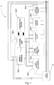
- the smart socket 1 comprises the following modules: a control unit 101, a communication module 201, a supply module 301, a current sensor 401, a voltage recording module 501, a load on/off relay 601, a power factor correction circuit 701, a relay module for interfacing towards the load 801 and possibly pins 901 for the direct connection between the load and the control unit.
- the unit is based, for example, on the PC Due board with the following specifications:
- different communication modules can be used for interfacing with the supervision unit including, for example, XBEE, Ethernet SHIELD, Bluetooth, WIFI Shield and the like.
- the supply module is produced by means of three supply sub-modules, each of which being composed of an isolation transformer, a diode bridge, capacitors and a voltage regulator, used for supplying respectively:
- the main components of the supply modules are: - Isolation transformer: it allows the grid voltage to be transformed into a lower voltage.
- - Isolation transformer it allows the grid voltage to be transformed into a lower voltage.
- the device is also conceived and developed to record voltages lower than 230 VAC (sag and undervoltage), consequently the secondary side voltage must lie within the range of admissible voltages going into the voltage regulator in these particular cases, too. Consequently, possible isolation transformer choices are: PRIMARY ADMISSIBLE VOLTAGE SECONDARY ADMISSIBLE VOLTAGE ISOLATION TRANSFORMER 0 / 400 VAC 0 / 24 VAC ISOLATION TRANSFORMER 0 / 500 VAC 0 / 36 VAC
- the isolation transformer is "only" used for transforming the grid voltage into a lower voltage and not as a measurement transformer, it can be replaced with a simple voltage divider, opportunely dimensioned, so as to generate an output voltage, which lies within the input range of the voltage regulator.
- the resistances chosen must be able to withstand the voltage to which they are subjected without burning.
- the board shown in fig. 2 comprises the sensor ACS714 developed by Allegro Microsystems. It is a linear current sensor based on the Hall effect, which has a low resistance ( ⁇ 1.2m) of the electric circuit and galvanic isolation higher than 2.1 kV RMS. This version accepts a module bidirectional input current higher than 30 A and an output proportionate to the recorded current value, centered on 2.5 V if supplied at 5 V, centered at 1.65 V if supplied at 3.3 V, with a typical error of ⁇ 1.5%.
- the sensor works at 5V and has a sensitivity of 66 mV/A.
- the module is used for acquiring the single samples of the instant voltage. With reference to fig. 4 , it is composed of:
- the relay is a switch with one or more electrical contacts driven by an electromagnet when the coil of the same is crossed by a current.
- This relay is controlled by the control unit based on the signal sent by the user via the control platform and allows the load to be activated or disabled from the mains.
- electronic switches such as SCR and the like can also be used.
- the power factor correction circuit is made up of three relays arranged parallel connected to an equal number of correction capacitors, which are activated by the control unit.
- the power factor correction unit has two operating modes:
- the power factor correction circuit comprises a battery of capacitors, in parallel, which can be excluded individually by means of break devices arranged in series, such as relays, electronic switches or the like, driven by the control unit, to introduce a capacitive reactance into the supply circuit of the load, so as to compensate, at least partially, for the inductive reactance of the load, so as to take the power factor to values higher than 0.7, preferably higher than 0.8, typically higher than 0.9.
- the module is made up of various relays or electronic switches, which are activated by the control unit according to the signal sent from the control platform allowing the socket to be connected directly to the single commands of the electric load, for example they can be used for replacing/supporting the electromechanical buttons found in various household appliances, so as to operate a particular program depending on the needs.
- the socket can be included as part of a system for monitoring the operating parameters of one or more loads in a power grid.
- a system for monitoring the operating parameters of one or more loads in a power grid.
- Such system whose block diagram is shown in fig.5 , comprises one or more supervision units 3 interfaced with one or more smart sockets 1 for reading data related to the mains voltage and current drawn by the load (s) 2 when such smart socket (s) are inserted in series between the electric mains and the load.
- the supervision unit 3 can remotely control both the socket 1 and the load 2 connected thereto, creating a node of a Smart Grid network.
- control unit 901 of the socket 1 can receive command signals sent by the user through the communication module 201, so as to remotely control both the turning on/off of the socket via the load on/off relay 601 and the selection of a particular load program by means of the load interface relay module 801 and/or the digital and analog pins 901 of the control unit 101.
- the latter function remote program selection
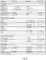
- the system is able to perform Power Quality analyses.
- This term refers to a wide range of electromagnetic phenomena, which characterize the voltage and/or current in a given point of the electric system.
- the IEEE proposed a subdivision of the phenomena, the root of disturbances caused in the electrical systems as shown in the table in fig. 6 .
Landscapes
- Engineering & Computer Science (AREA)
- Power Engineering (AREA)
- Physics & Mathematics (AREA)
- General Physics & Mathematics (AREA)
- Remote Monitoring And Control Of Power-Distribution Networks (AREA)
- Control Of Electrical Variables (AREA)
- Selective Calling Equipment (AREA)
Claims (10)
- Intelligente Steckdose (1) zur Überwachung elektrischer Betriebsparameter einer Last, wobei die intelligente Steckdose in Reihe zwischen der Last und einem Netz eingefügt ist, umfassend:mindestens einen Spannungssensor (501) und einen Stromsensor (401), die mit einer Steuereinheit (101) verbunden sind, die so konfiguriert ist, dass sie die Werte der elektrischen Netzspannung und des entnommenen Stroms abliest, wenn die Steckdose zwischen die Last und das Stromnetz geschaltet ist;ein Kommunikationsmodul (201), das über eine Schnittstelle mit der Steuereinheit (101) verbunden ist und so konfiguriert ist, dass es Daten sendet und Steuerungen von einer entfernten Überwachungseinheit (3) empfängt;Laststeuerungsvorrichtungen (601, 701, 801, 901), die so konfiguriert sind, dass sie gemäß den vom Kommunikationsmodul (201) empfangenen Steuerungen und/oder gemäß den in der Steuereinheit (101) voreingestellten Steuerungen arbeiten;dadurch gekennzeichnet, dass die Laststeuervorrichtungen eine Leistungsfaktorkorrekturschaltung (701) umfassen, die eine Batterie von parallel geschalteten Kondensatoren umfasst, die einzeln durch in Reihe angeordnete Unterbrechungsvorrichtungen, wie Relais, elektronische Schalter oder dergleichen, ausgeschlossen werden können, die von der Steuereinheit (101) angesteuert werden, um eine kapazitive Reaktanz in den Versorgungskreis der Last (2) einzuführen, um die induktive Reaktanz der Last zumindest teilweise zu kompensieren, um den Leistungsfaktor auf Werte über 0,7, vorzugsweise über 0,8, typischerweise über 0,9 zu bringen.
- Steckdose (1) nach Anspruch 1, wobei die Laststeuereinrichtungen Module (601) umfassen, die auf den Versorgungskreis der Last (2) einwirken.
- Steckdose (1) nach Anspruch 2, wobei die Module (601), die auf die Versorgung der Last (2) einwirken, eine Unterbrechungsvorrichtung des Stromkreislaufs an der Last umfassen, wie z. B. ein Relais, einen elektronischen Schalter oder dergleichen, der von der Steuereinheit angesteuert wird, um die Last ein-/auszuschalten.
- Steckdose (1) nach einem oder mehreren der vorhergehenden Ansprüche, wobei die Laststeuervorrichtungen Elemente (801, 901) umfassen, die so konfiguriert sind, dass sie eine Schnittstelle zwischen der Steuereinheit (101) und der Last (2) bilden, so dass die Steuereinheit (101) zumindest einen Teil der jeweiligen Betriebsparameter direkt an der Last (2) einstellen kann.
- Steckdose (1) nach einem oder mehreren der vorhergehenden Ansprüche, wobei die Steuereinheit (101) so konfiguriert ist, dass sie Steuersignale von der Überwachungseinheit (3) empfängt, um den Betrieb der Last (2) aus der Ferne ein- und auszuschalten und mehr im Allgemeinen zu steuern und somit den Verbrauch oder andere Leistungsindizes entsprechend den überwachten Betriebsparametern zu optimieren.
- System zur Überwachung von Betriebsparametern einer oder mehrerer in einem Netz vorhandener Lasten, wobei das System eine oder mehrere Überwachungseinheiten (3) umfasst, die mit einer oder mehreren intelligenten Steckdosen (1) gemäß einem oder mehreren der vorhergehenden Ansprüche verbunden sind, um Daten zu lesen, die sich auf die elektrische Netzspannung und den von der/den Last(en) (2) aufgenommenen Strom beziehen, wenn diese intelligente(n) Steckdose(n) (1) in Reihe zwischen das elektrische Netz und der Last geschaltet sind.
- System nach Anspruch 6, wobei die Überwachungseinheit (3) mit der/den intelligenten Steckdose(n) (1) über ein drahtgebundenes oder drahtloses Netzwerk verbunden ist, insbesondere über Bluetooth, Wifi, Zigbee-Netzwerke oder dergleichen.
- System nach Anspruch 6 oder 7, wobei die Überwachungseinheit (3) so konfiguriert ist, dass sie elektrische Parameter mittels einer oder mehrerer intelligenter Steckdosen (1) liest und solche Parameter verarbeitet, um eine Energiequalitätsanalyse des Netzes auszugeben.
- System nach Anspruch 8, wobei die Energiequalitätsanalyse die Verarbeitung eines oder mehrerer Parameter umfasst, die aus der Liste ausgewählt sind, welche aus Folgendem besteht: effektiver Spannungswert, mittlerer Spannungswert, maximaler Spannungswert, minimaler Spannungswert, effektiver Stromwert, mittlerer Stromwert, maximaler Stromwert, minimaler Stromwert, Leistungsfaktor, Wirkleistung, Blindleistung, Scheinleistung.
- System nach Anspruch 8 oder 9, wobei die Energiequalitätsanalyse die Extrapolation einer oder mehrerer Kategorien elektrischer Störungen der elektrischen Netzspannung umfasst, die ausgewählt werden aus der Gruppe bestehend aus: Impulstransienten, oszillierende Transienten, momentane Kurzzeitschwankungen, kurzzeitige Kurzzeitschwankungen, vorübergehende Kurzzeitschwankungen, Langzeitschwankungen, längere Unterbrechungen, Unterspannungen, Überspannungen, Abweichungen, Verzerrungen durch Gleichstromversatz, harmonische Verzerrungen, interharmonische Verzerrungen, Kerbverzerrungen, Breitbandrauschverzerrungen, Spannungsschwankungsverzerrungen, Frequenzschwankungsverzerrungen.
Applications Claiming Priority (2)
| Application Number | Priority Date | Filing Date | Title |
|---|---|---|---|
| IT102016000123334A IT201600123334A1 (it) | 2016-12-05 | 2016-12-05 | Presa intelligente e sistema di monitoraggio e controllo utilizzante detta presa |
| PCT/IB2017/057634 WO2018104849A1 (en) | 2016-12-05 | 2017-12-05 | A smart socket and monitoring and control system using said socket |
Publications (2)
| Publication Number | Publication Date |
|---|---|
| EP3549227A1 EP3549227A1 (de) | 2019-10-09 |
| EP3549227B1 true EP3549227B1 (de) | 2021-10-27 |
Family
ID=58609760
Family Applications (1)
| Application Number | Title | Priority Date | Filing Date |
|---|---|---|---|
| EP17826279.6A Active EP3549227B1 (de) | 2016-12-05 | 2017-12-05 | Intelligente buchse sowie überwachungs- und steuerungssystem mit der besagten buchse |
Country Status (4)
| Country | Link |
|---|---|
| US (1) | US20200153272A1 (de) |
| EP (1) | EP3549227B1 (de) |
| IT (1) | IT201600123334A1 (de) |
| WO (1) | WO2018104849A1 (de) |
Families Citing this family (7)
| Publication number | Priority date | Publication date | Assignee | Title |
|---|---|---|---|---|
| CN111064280A (zh) * | 2019-12-16 | 2020-04-24 | 嵊州市法佳电器有限公司 | 一种通过pwm波调节的无线插座 |
| IT201900025855A1 (it) | 2019-12-31 | 2021-07-01 | Univ Degli Studi Di Firenze | Sistema per il monitoraggio e l’analisi di parametri elettrici |
| CN111541735A (zh) * | 2020-03-12 | 2020-08-14 | 国网河北省电力有限公司雄安新区供电公司 | 直流自适应端口物联网系统及其控制方法 |
| US11894638B2 (en) * | 2020-07-27 | 2024-02-06 | Illinois Institute Of Technology | Solid state protective smart plug device |
| CN114142303B (zh) * | 2021-12-02 | 2024-02-09 | 彭宇晨 | 智慧插座及火灾防护方法、云端服务器 |
| CN116799572A (zh) * | 2023-06-26 | 2023-09-22 | 南京惠派智慧后勤服务有限公司 | 一种基于无线网络控制的节能型分体式空调插座 |
| CN117375120B (zh) * | 2023-12-07 | 2024-02-06 | 深圳市鼎阳科技股份有限公司 | 电源及电源的工作方法 |
Citations (3)
| Publication number | Priority date | Publication date | Assignee | Title |
|---|---|---|---|---|
| CN204992153U (zh) * | 2015-07-28 | 2016-01-20 | 北京智芯微电子科技有限公司 | 一种基于Wi-Fi的多功能智能插座 |
| US20160156225A1 (en) * | 2014-12-01 | 2016-06-02 | Eaton Corporation | Load power device and system for real-time execution of hierarchical load identification algorithms |
| CN205543522U (zh) * | 2016-01-22 | 2016-08-31 | 浙江新再灵科技股份有限公司 | 可自动进行无功耗补偿的智能插座 |
Family Cites Families (5)
| Publication number | Priority date | Publication date | Assignee | Title |
|---|---|---|---|---|
| US7795759B2 (en) * | 2008-06-27 | 2010-09-14 | iGo, Inc | Load condition controlled power strip |
| JP5865842B2 (ja) * | 2010-01-25 | 2016-02-17 | ジェネヴァ クリーンテック インコーポレイテッド | 歪み低減装置 |
| US8583955B2 (en) * | 2011-10-04 | 2013-11-12 | Advanergy, Inc. | Battery management system and method |
| US8649883B2 (en) * | 2011-10-04 | 2014-02-11 | Advanergy, Inc. | Power distribution system and method |
| US8872390B2 (en) * | 2012-10-31 | 2014-10-28 | SSI America, Inc. | Wireless communication-enabled energy consumption monitor and mobile application for same |
-
2016
- 2016-12-05 IT IT102016000123334A patent/IT201600123334A1/it unknown
-
2017
- 2017-12-05 EP EP17826279.6A patent/EP3549227B1/de active Active
- 2017-12-05 WO PCT/IB2017/057634 patent/WO2018104849A1/en active Application Filing
- 2017-12-05 US US16/466,498 patent/US20200153272A1/en not_active Abandoned
Patent Citations (3)
| Publication number | Priority date | Publication date | Assignee | Title |
|---|---|---|---|---|
| US20160156225A1 (en) * | 2014-12-01 | 2016-06-02 | Eaton Corporation | Load power device and system for real-time execution of hierarchical load identification algorithms |
| CN204992153U (zh) * | 2015-07-28 | 2016-01-20 | 北京智芯微电子科技有限公司 | 一种基于Wi-Fi的多功能智能插座 |
| CN205543522U (zh) * | 2016-01-22 | 2016-08-31 | 浙江新再灵科技股份有限公司 | 可自动进行无功耗补偿的智能插座 |
Also Published As
| Publication number | Publication date |
|---|---|
| EP3549227A1 (de) | 2019-10-09 |
| US20200153272A1 (en) | 2020-05-14 |
| WO2018104849A1 (en) | 2018-06-14 |
| IT201600123334A1 (it) | 2018-06-05 |
Similar Documents
| Publication | Publication Date | Title |
|---|---|---|
| EP3549227B1 (de) | Intelligente buchse sowie überwachungs- und steuerungssystem mit der besagten buchse | |
| US11043811B2 (en) | Reactive power control method, device and system | |
| US7573253B2 (en) | System for managing electrical consumption | |
| US7009379B2 (en) | Electricity meter with power supply load management | |
| KR20220062116A (ko) | 전기적 부하를 관리하는 시스템 및 방법 | |
| Uluski | VVC in the smart grid era | |
| JP6879912B2 (ja) | 無効電力量の消費を最適化する方法 | |
| CN105723588A (zh) | 不间断电源控制 | |
| AU2011202502A1 (en) | Systems and apparatus for monitoring and selectively controlling a load in a power system | |
| US20110077878A1 (en) | Power supply with data communications | |
| US6384583B1 (en) | Power pod controller system | |
| JP6782442B2 (ja) | 計測装置、計測システム及びコンピュータシステム | |
| US20100061028A1 (en) | System for managing electrical consumption with coaxial communication line protection | |
| US9859049B2 (en) | System for reducing electrical consumption with triple core iterative transformers | |
| KR101073809B1 (ko) | 스마트 대기전력 자동차단 스위치 | |
| KR20200061200A (ko) | 변전소 운전 제어 장치 및 그의 제어방법 | |
| US20150256090A1 (en) | Systems for reducing electrical consumption using triple core iterative transformers | |
| US6448747B1 (en) | Electricity pod controller device | |
| US11239659B2 (en) | Microgrid autosynchronizing using remote recloser inputs and outputs | |
| CN204304602U (zh) | 防晃电装置 | |
| Vani | Distribution and Load Sharing of Transformer Automatically by Using Microcontroller | |
| CN219554657U (zh) | 一种照明电源配电优化设备 | |
| US11921532B2 (en) | Controlling pulsed operation of a power supply during a power outage | |
| CN202817774U (zh) | 一种低压电网无功补偿远动系统 | |
| Sedhuraman et al. | Performance Investigation of Smart Integrated Circuit Breaker Using Raspberry Pi and Arduino Controller |
Legal Events
| Date | Code | Title | Description |
|---|---|---|---|
| STAA | Information on the status of an ep patent application or granted ep patent |
Free format text: STATUS: UNKNOWN |
|
| STAA | Information on the status of an ep patent application or granted ep patent |
Free format text: STATUS: THE INTERNATIONAL PUBLICATION HAS BEEN MADE |
|
| PUAI | Public reference made under article 153(3) epc to a published international application that has entered the european phase |
Free format text: ORIGINAL CODE: 0009012 |
|
| STAA | Information on the status of an ep patent application or granted ep patent |
Free format text: STATUS: REQUEST FOR EXAMINATION WAS MADE |
|
| 17P | Request for examination filed |
Effective date: 20190702 |
|
| AK | Designated contracting states |
Kind code of ref document: A1 Designated state(s): AL AT BE BG CH CY CZ DE DK EE ES FI FR GB GR HR HU IE IS IT LI LT LU LV MC MK MT NL NO PL PT RO RS SE SI SK SM TR |
|
| AX | Request for extension of the european patent |
Extension state: BA ME |
|
| DAV | Request for validation of the european patent (deleted) | ||
| DAX | Request for extension of the european patent (deleted) | ||
| STAA | Information on the status of an ep patent application or granted ep patent |
Free format text: STATUS: EXAMINATION IS IN PROGRESS |
|
| 17Q | First examination report despatched |
Effective date: 20200610 |
|
| STAA | Information on the status of an ep patent application or granted ep patent |
Free format text: STATUS: EXAMINATION IS IN PROGRESS |
|
| GRAP | Despatch of communication of intention to grant a patent |
Free format text: ORIGINAL CODE: EPIDOSNIGR1 |
|
| STAA | Information on the status of an ep patent application or granted ep patent |
Free format text: STATUS: GRANT OF PATENT IS INTENDED |
|
| INTG | Intention to grant announced |
Effective date: 20210519 |
|
| GRAS | Grant fee paid |
Free format text: ORIGINAL CODE: EPIDOSNIGR3 |
|
| GRAA | (expected) grant |
Free format text: ORIGINAL CODE: 0009210 |
|
| STAA | Information on the status of an ep patent application or granted ep patent |
Free format text: STATUS: THE PATENT HAS BEEN GRANTED |
|
| AK | Designated contracting states |
Kind code of ref document: B1 Designated state(s): AL AT BE BG CH CY CZ DE DK EE ES FI FR GB GR HR HU IE IS IT LI LT LU LV MC MK MT NL NO PL PT RO RS SE SI SK SM TR |
|
| REG | Reference to a national code |
Ref country code: GB Ref legal event code: FG4D |
|
| REG | Reference to a national code |
Ref country code: CH Ref legal event code: EP |
|
| REG | Reference to a national code |
Ref country code: DE Ref legal event code: R096 Ref document number: 602017048406 Country of ref document: DE |
|
| REG | Reference to a national code |
Ref country code: AT Ref legal event code: REF Ref document number: 1442705 Country of ref document: AT Kind code of ref document: T Effective date: 20211115 |
|
| REG | Reference to a national code |
Ref country code: IE Ref legal event code: FG4D |
|
| REG | Reference to a national code |
Ref country code: LT Ref legal event code: MG9D |
|
| REG | Reference to a national code |
Ref country code: NL Ref legal event code: MP Effective date: 20211027 |
|
| REG | Reference to a national code |
Ref country code: AT Ref legal event code: MK05 Ref document number: 1442705 Country of ref document: AT Kind code of ref document: T Effective date: 20211027 |
|
| PG25 | Lapsed in a contracting state [announced via postgrant information from national office to epo] |
Ref country code: RS Free format text: LAPSE BECAUSE OF FAILURE TO SUBMIT A TRANSLATION OF THE DESCRIPTION OR TO PAY THE FEE WITHIN THE PRESCRIBED TIME-LIMIT Effective date: 20211027 Ref country code: LT Free format text: LAPSE BECAUSE OF FAILURE TO SUBMIT A TRANSLATION OF THE DESCRIPTION OR TO PAY THE FEE WITHIN THE PRESCRIBED TIME-LIMIT Effective date: 20211027 Ref country code: FI Free format text: LAPSE BECAUSE OF FAILURE TO SUBMIT A TRANSLATION OF THE DESCRIPTION OR TO PAY THE FEE WITHIN THE PRESCRIBED TIME-LIMIT Effective date: 20211027 Ref country code: BG Free format text: LAPSE BECAUSE OF FAILURE TO SUBMIT A TRANSLATION OF THE DESCRIPTION OR TO PAY THE FEE WITHIN THE PRESCRIBED TIME-LIMIT Effective date: 20220127 Ref country code: AT Free format text: LAPSE BECAUSE OF FAILURE TO SUBMIT A TRANSLATION OF THE DESCRIPTION OR TO PAY THE FEE WITHIN THE PRESCRIBED TIME-LIMIT Effective date: 20211027 |
|
| PG25 | Lapsed in a contracting state [announced via postgrant information from national office to epo] |
Ref country code: IS Free format text: LAPSE BECAUSE OF FAILURE TO SUBMIT A TRANSLATION OF THE DESCRIPTION OR TO PAY THE FEE WITHIN THE PRESCRIBED TIME-LIMIT Effective date: 20220227 Ref country code: SE Free format text: LAPSE BECAUSE OF FAILURE TO SUBMIT A TRANSLATION OF THE DESCRIPTION OR TO PAY THE FEE WITHIN THE PRESCRIBED TIME-LIMIT Effective date: 20211027 Ref country code: PT Free format text: LAPSE BECAUSE OF FAILURE TO SUBMIT A TRANSLATION OF THE DESCRIPTION OR TO PAY THE FEE WITHIN THE PRESCRIBED TIME-LIMIT Effective date: 20220228 Ref country code: PL Free format text: LAPSE BECAUSE OF FAILURE TO SUBMIT A TRANSLATION OF THE DESCRIPTION OR TO PAY THE FEE WITHIN THE PRESCRIBED TIME-LIMIT Effective date: 20211027 Ref country code: NO Free format text: LAPSE BECAUSE OF FAILURE TO SUBMIT A TRANSLATION OF THE DESCRIPTION OR TO PAY THE FEE WITHIN THE PRESCRIBED TIME-LIMIT Effective date: 20220127 Ref country code: NL Free format text: LAPSE BECAUSE OF FAILURE TO SUBMIT A TRANSLATION OF THE DESCRIPTION OR TO PAY THE FEE WITHIN THE PRESCRIBED TIME-LIMIT Effective date: 20211027 Ref country code: LV Free format text: LAPSE BECAUSE OF FAILURE TO SUBMIT A TRANSLATION OF THE DESCRIPTION OR TO PAY THE FEE WITHIN THE PRESCRIBED TIME-LIMIT Effective date: 20211027 Ref country code: HR Free format text: LAPSE BECAUSE OF FAILURE TO SUBMIT A TRANSLATION OF THE DESCRIPTION OR TO PAY THE FEE WITHIN THE PRESCRIBED TIME-LIMIT Effective date: 20211027 Ref country code: GR Free format text: LAPSE BECAUSE OF FAILURE TO SUBMIT A TRANSLATION OF THE DESCRIPTION OR TO PAY THE FEE WITHIN THE PRESCRIBED TIME-LIMIT Effective date: 20220128 Ref country code: ES Free format text: LAPSE BECAUSE OF FAILURE TO SUBMIT A TRANSLATION OF THE DESCRIPTION OR TO PAY THE FEE WITHIN THE PRESCRIBED TIME-LIMIT Effective date: 20211027 |
|
| REG | Reference to a national code |
Ref country code: DE Ref legal event code: R097 Ref document number: 602017048406 Country of ref document: DE |
|
| PG25 | Lapsed in a contracting state [announced via postgrant information from national office to epo] |
Ref country code: SM Free format text: LAPSE BECAUSE OF FAILURE TO SUBMIT A TRANSLATION OF THE DESCRIPTION OR TO PAY THE FEE WITHIN THE PRESCRIBED TIME-LIMIT Effective date: 20211027 Ref country code: SK Free format text: LAPSE BECAUSE OF FAILURE TO SUBMIT A TRANSLATION OF THE DESCRIPTION OR TO PAY THE FEE WITHIN THE PRESCRIBED TIME-LIMIT Effective date: 20211027 Ref country code: RO Free format text: LAPSE BECAUSE OF FAILURE TO SUBMIT A TRANSLATION OF THE DESCRIPTION OR TO PAY THE FEE WITHIN THE PRESCRIBED TIME-LIMIT Effective date: 20211027 Ref country code: MC Free format text: LAPSE BECAUSE OF FAILURE TO SUBMIT A TRANSLATION OF THE DESCRIPTION OR TO PAY THE FEE WITHIN THE PRESCRIBED TIME-LIMIT Effective date: 20211027 Ref country code: EE Free format text: LAPSE BECAUSE OF FAILURE TO SUBMIT A TRANSLATION OF THE DESCRIPTION OR TO PAY THE FEE WITHIN THE PRESCRIBED TIME-LIMIT Effective date: 20211027 Ref country code: DK Free format text: LAPSE BECAUSE OF FAILURE TO SUBMIT A TRANSLATION OF THE DESCRIPTION OR TO PAY THE FEE WITHIN THE PRESCRIBED TIME-LIMIT Effective date: 20211027 Ref country code: CZ Free format text: LAPSE BECAUSE OF FAILURE TO SUBMIT A TRANSLATION OF THE DESCRIPTION OR TO PAY THE FEE WITHIN THE PRESCRIBED TIME-LIMIT Effective date: 20211027 |
|
| PLBE | No opposition filed within time limit |
Free format text: ORIGINAL CODE: 0009261 |
|
| STAA | Information on the status of an ep patent application or granted ep patent |
Free format text: STATUS: NO OPPOSITION FILED WITHIN TIME LIMIT |
|
| REG | Reference to a national code |
Ref country code: BE Ref legal event code: MM Effective date: 20211231 |
|
| 26N | No opposition filed |
Effective date: 20220728 |
|
| PG25 | Lapsed in a contracting state [announced via postgrant information from national office to epo] |
Ref country code: LU Free format text: LAPSE BECAUSE OF NON-PAYMENT OF DUE FEES Effective date: 20211205 Ref country code: IE Free format text: LAPSE BECAUSE OF NON-PAYMENT OF DUE FEES Effective date: 20211205 Ref country code: AL Free format text: LAPSE BECAUSE OF FAILURE TO SUBMIT A TRANSLATION OF THE DESCRIPTION OR TO PAY THE FEE WITHIN THE PRESCRIBED TIME-LIMIT Effective date: 20211027 |
|
| PG25 | Lapsed in a contracting state [announced via postgrant information from national office to epo] |
Ref country code: SI Free format text: LAPSE BECAUSE OF FAILURE TO SUBMIT A TRANSLATION OF THE DESCRIPTION OR TO PAY THE FEE WITHIN THE PRESCRIBED TIME-LIMIT Effective date: 20211027 Ref country code: BE Free format text: LAPSE BECAUSE OF NON-PAYMENT OF DUE FEES Effective date: 20211231 |
|
| PGFP | Annual fee paid to national office [announced via postgrant information from national office to epo] |
Ref country code: CH Payment date: 20230101 Year of fee payment: 6 |
|
| PG25 | Lapsed in a contracting state [announced via postgrant information from national office to epo] |
Ref country code: CY Free format text: LAPSE BECAUSE OF FAILURE TO SUBMIT A TRANSLATION OF THE DESCRIPTION OR TO PAY THE FEE WITHIN THE PRESCRIBED TIME-LIMIT Effective date: 20211027 |
|
| PG25 | Lapsed in a contracting state [announced via postgrant information from national office to epo] |
Ref country code: HU Free format text: LAPSE BECAUSE OF FAILURE TO SUBMIT A TRANSLATION OF THE DESCRIPTION OR TO PAY THE FEE WITHIN THE PRESCRIBED TIME-LIMIT; INVALID AB INITIO Effective date: 20171205 |
|
| PGFP | Annual fee paid to national office [announced via postgrant information from national office to epo] |
Ref country code: FR Payment date: 20230929 Year of fee payment: 7 |
|
| PGFP | Annual fee paid to national office [announced via postgrant information from national office to epo] |
Ref country code: GB Payment date: 20231012 Year of fee payment: 7 |
|
| PGFP | Annual fee paid to national office [announced via postgrant information from national office to epo] |
Ref country code: IT Payment date: 20231127 Year of fee payment: 7 Ref country code: DE Payment date: 20231010 Year of fee payment: 7 |
|
| PG25 | Lapsed in a contracting state [announced via postgrant information from national office to epo] |
Ref country code: MK Free format text: LAPSE BECAUSE OF FAILURE TO SUBMIT A TRANSLATION OF THE DESCRIPTION OR TO PAY THE FEE WITHIN THE PRESCRIBED TIME-LIMIT Effective date: 20211027 |
|
| PGFP | Annual fee paid to national office [announced via postgrant information from national office to epo] |
Ref country code: CH Payment date: 20240101 Year of fee payment: 7 |