EP3549227B1 - A smart socket and monitoring and control system using said socket - Google Patents
A smart socket and monitoring and control system using said socket Download PDFInfo
- Publication number
- EP3549227B1 EP3549227B1 EP17826279.6A EP17826279A EP3549227B1 EP 3549227 B1 EP3549227 B1 EP 3549227B1 EP 17826279 A EP17826279 A EP 17826279A EP 3549227 B1 EP3549227 B1 EP 3549227B1
- Authority
- EP
- European Patent Office
- Prior art keywords
- load
- socket
- voltage
- control unit
- smart
- Prior art date
- Legal status (The legal status is an assumption and is not a legal conclusion. Google has not performed a legal analysis and makes no representation as to the accuracy of the status listed.)
- Active
Links
- 238000012544 monitoring process Methods 0.000 title claims description 6
- 238000012937 correction Methods 0.000 claims description 13
- 239000003990 capacitor Substances 0.000 claims description 7
- 238000004891 communication Methods 0.000 claims description 6
- 238000004458 analytical method Methods 0.000 claims description 5
- 238000000034 method Methods 0.000 claims description 4
- 230000008569 process Effects 0.000 claims description 4
- 238000012545 processing Methods 0.000 claims description 4
- 230000001939 inductive effect Effects 0.000 claims description 3
- 230000003534 oscillatory effect Effects 0.000 claims 1
- 230000002035 prolonged effect Effects 0.000 claims 1
- 238000005259 measurement Methods 0.000 description 9
- 238000002955 isolation Methods 0.000 description 7
- 238000005070 sampling Methods 0.000 description 5
- 238000010586 diagram Methods 0.000 description 4
- 230000009467 reduction Effects 0.000 description 3
- 230000005355 Hall effect Effects 0.000 description 2
- 230000008901 benefit Effects 0.000 description 2
- 230000002457 bidirectional effect Effects 0.000 description 2
- 238000004353 relayed correlation spectroscopy Methods 0.000 description 2
- 230000009471 action Effects 0.000 description 1
- 230000002860 competitive effect Effects 0.000 description 1
- 239000004020 conductor Substances 0.000 description 1
- 230000006378 damage Effects 0.000 description 1
- 230000000694 effects Effects 0.000 description 1
- 230000006872 improvement Effects 0.000 description 1
- 238000007726 management method Methods 0.000 description 1
- 230000007246 mechanism Effects 0.000 description 1
- 238000010223 real-time analysis Methods 0.000 description 1
- 230000035945 sensitivity Effects 0.000 description 1
- 230000006641 stabilisation Effects 0.000 description 1
- 238000011105 stabilization Methods 0.000 description 1
- 230000001131 transforming effect Effects 0.000 description 1
Images


Classifications
-
- H—ELECTRICITY
- H02—GENERATION; CONVERSION OR DISTRIBUTION OF ELECTRIC POWER
- H02J—CIRCUIT ARRANGEMENTS OR SYSTEMS FOR SUPPLYING OR DISTRIBUTING ELECTRIC POWER; SYSTEMS FOR STORING ELECTRIC ENERGY
- H02J13/00—Circuit arrangements for providing remote indication of network conditions, e.g. an instantaneous record of the open or closed condition of each circuitbreaker in the network; Circuit arrangements for providing remote control of switching means in a power distribution network, e.g. switching in and out of current consumers by using a pulse code signal carried by the network
- H02J13/00002—Circuit arrangements for providing remote indication of network conditions, e.g. an instantaneous record of the open or closed condition of each circuitbreaker in the network; Circuit arrangements for providing remote control of switching means in a power distribution network, e.g. switching in and out of current consumers by using a pulse code signal carried by the network characterised by monitoring
-
- H—ELECTRICITY
- H02—GENERATION; CONVERSION OR DISTRIBUTION OF ELECTRIC POWER
- H02J—CIRCUIT ARRANGEMENTS OR SYSTEMS FOR SUPPLYING OR DISTRIBUTING ELECTRIC POWER; SYSTEMS FOR STORING ELECTRIC ENERGY
- H02J4/00—Circuit arrangements for mains or distribution networks not specified as ac or dc
-
- G—PHYSICS
- G01—MEASURING; TESTING
- G01R—MEASURING ELECTRIC VARIABLES; MEASURING MAGNETIC VARIABLES
- G01R21/00—Arrangements for measuring electric power or power factor
- G01R21/06—Arrangements for measuring electric power or power factor by measuring current and voltage
-
- H—ELECTRICITY
- H02—GENERATION; CONVERSION OR DISTRIBUTION OF ELECTRIC POWER
- H02J—CIRCUIT ARRANGEMENTS OR SYSTEMS FOR SUPPLYING OR DISTRIBUTING ELECTRIC POWER; SYSTEMS FOR STORING ELECTRIC ENERGY
- H02J13/00—Circuit arrangements for providing remote indication of network conditions, e.g. an instantaneous record of the open or closed condition of each circuitbreaker in the network; Circuit arrangements for providing remote control of switching means in a power distribution network, e.g. switching in and out of current consumers by using a pulse code signal carried by the network
- H02J13/00006—Circuit arrangements for providing remote indication of network conditions, e.g. an instantaneous record of the open or closed condition of each circuitbreaker in the network; Circuit arrangements for providing remote control of switching means in a power distribution network, e.g. switching in and out of current consumers by using a pulse code signal carried by the network characterised by information or instructions transport means between the monitoring, controlling or managing units and monitored, controlled or operated power network element or electrical equipment
-
- H—ELECTRICITY
- H02—GENERATION; CONVERSION OR DISTRIBUTION OF ELECTRIC POWER
- H02J—CIRCUIT ARRANGEMENTS OR SYSTEMS FOR SUPPLYING OR DISTRIBUTING ELECTRIC POWER; SYSTEMS FOR STORING ELECTRIC ENERGY
- H02J3/00—Circuit arrangements for ac mains or ac distribution networks
- H02J3/18—Arrangements for adjusting, eliminating or compensating reactive power in networks
-
- Y—GENERAL TAGGING OF NEW TECHNOLOGICAL DEVELOPMENTS; GENERAL TAGGING OF CROSS-SECTIONAL TECHNOLOGIES SPANNING OVER SEVERAL SECTIONS OF THE IPC; TECHNICAL SUBJECTS COVERED BY FORMER USPC CROSS-REFERENCE ART COLLECTIONS [XRACs] AND DIGESTS
- Y02—TECHNOLOGIES OR APPLICATIONS FOR MITIGATION OR ADAPTATION AGAINST CLIMATE CHANGE
- Y02B—CLIMATE CHANGE MITIGATION TECHNOLOGIES RELATED TO BUILDINGS, e.g. HOUSING, HOUSE APPLIANCES OR RELATED END-USER APPLICATIONS
- Y02B90/00—Enabling technologies or technologies with a potential or indirect contribution to GHG emissions mitigation
- Y02B90/20—Smart grids as enabling technology in buildings sector
-
- Y—GENERAL TAGGING OF NEW TECHNOLOGICAL DEVELOPMENTS; GENERAL TAGGING OF CROSS-SECTIONAL TECHNOLOGIES SPANNING OVER SEVERAL SECTIONS OF THE IPC; TECHNICAL SUBJECTS COVERED BY FORMER USPC CROSS-REFERENCE ART COLLECTIONS [XRACs] AND DIGESTS
- Y02—TECHNOLOGIES OR APPLICATIONS FOR MITIGATION OR ADAPTATION AGAINST CLIMATE CHANGE
- Y02E—REDUCTION OF GREENHOUSE GAS [GHG] EMISSIONS, RELATED TO ENERGY GENERATION, TRANSMISSION OR DISTRIBUTION
- Y02E40/00—Technologies for an efficient electrical power generation, transmission or distribution
- Y02E40/30—Reactive power compensation
-
- Y—GENERAL TAGGING OF NEW TECHNOLOGICAL DEVELOPMENTS; GENERAL TAGGING OF CROSS-SECTIONAL TECHNOLOGIES SPANNING OVER SEVERAL SECTIONS OF THE IPC; TECHNICAL SUBJECTS COVERED BY FORMER USPC CROSS-REFERENCE ART COLLECTIONS [XRACs] AND DIGESTS
- Y04—INFORMATION OR COMMUNICATION TECHNOLOGIES HAVING AN IMPACT ON OTHER TECHNOLOGY AREAS
- Y04S—SYSTEMS INTEGRATING TECHNOLOGIES RELATED TO POWER NETWORK OPERATION, COMMUNICATION OR INFORMATION TECHNOLOGIES FOR IMPROVING THE ELECTRICAL POWER GENERATION, TRANSMISSION, DISTRIBUTION, MANAGEMENT OR USAGE, i.e. SMART GRIDS
- Y04S40/00—Systems for electrical power generation, transmission, distribution or end-user application management characterised by the use of communication or information technologies, or communication or information technology specific aspects supporting them
- Y04S40/12—Systems for electrical power generation, transmission, distribution or end-user application management characterised by the use of communication or information technologies, or communication or information technology specific aspects supporting them characterised by data transport means between the monitoring, controlling or managing units and monitored, controlled or operated electrical equipment
Definitions
- the invention relates to the sector of Smart Grids and Smart Metering within the scope of power grids.
- Smart Grid is understood to mean an infrastructure/network controlled smartly, so as to be able to manage the various power flows consciously and provide end users with competitive prices.
- Smart Grid is a power supply, which efficiently integrates and manages the conduct and action of all users connected to the power supply (generators, sampling points, and generation and sampling points) with the aim of guaranteeing a financially efficient operation of the electrical system, with low losses, an elevated level of safety and continuity and quality of the supply.
- Smart Grids A fundamental part of Smart Grids is Smart Metering, the object of which is to know consumption profiles in real time, thus giving power supply operators the right to create mechanisms provided with greater flexibility, dynamicity, offering customers, the energy consumers, a greater understanding and awareness of their consumptions.
- a fundamental requisite of Smart Meter is the possibility to record various users' consumption in real-time and send the remotely acquired data.
- Smart sockets in jargon, which can measure electrical magnitudes, in particular grid voltage and current absorbed by the load. Although they carry out their role perfectly, they are nonetheless very specific devices able to process the values measured locally and provide broad indications regarding various electrical parameters, such as the power absorbed by the load, which can be used by the power supply operators to offer customers differentiated contracts based on the specific consumption characteristics. Furthermore, the Smart Grid requires sampling capacities and data processing, which go way beyond simple signal samplings and the relative processing.
- Document CN204992153 discloses an example of multi -functional smart socket based on Wi -Fi interfacing and connection.
- Document US2016/156225 discloses another example of multi -functional smart socket configured to provide real-time analysis of the main and connected loads.
- Document CN205543522 discloses yet another example of smart socket adapted to monitor active and reactive power to and from the mains network.
- the invention achieves the object with a smart socket according to claim 1.
- the socket is not limited to reading voltage and current data, but interacts strongly with the load thanks to the dialogue with one or more remote supervision units, which can read and process such data and send commands to control and optimize the working of the mains.
- the load control devices can comprise simple modules, which act on the load supply circuit, for example, using a break device for the current circulation on the load, such as a relay, an electronic switch or the like, or, combined, either a power factor correction circuit, which reduces the reactive power on the load, or combined, elements, which allow the control unit to interface with the load, so as to allow the control unit to set at least part of the relative operating parameters directly on the load.
- a break device for the current circulation on the load such as a relay, an electronic switch or the like
- a power factor correction circuit which reduces the reactive power on the load, or combined, elements, which allow the control unit to interface with the load, so as to allow the control unit to set at least part of the relative operating parameters directly on the load.
- control unit is advantageously configured to receive control signals from the supervision unit for remotely controlling the turning on/ off and, more generally, the working of the load, optimizing consumption or other performance indexes according to the operating parameters monitored.
- the invention relates to a system according to claim 6.
- the supervision unit can be configured to process parameters from the smart socket(s) to provide an output Power Quality analysis of the mains.
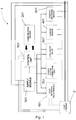
- the smart socket 1 comprises the following modules: a control unit 101, a communication module 201, a supply module 301, a current sensor 401, a voltage recording module 501, a load on/off relay 601, a power factor correction circuit 701, a relay module for interfacing towards the load 801 and possibly pins 901 for the direct connection between the load and the control unit.
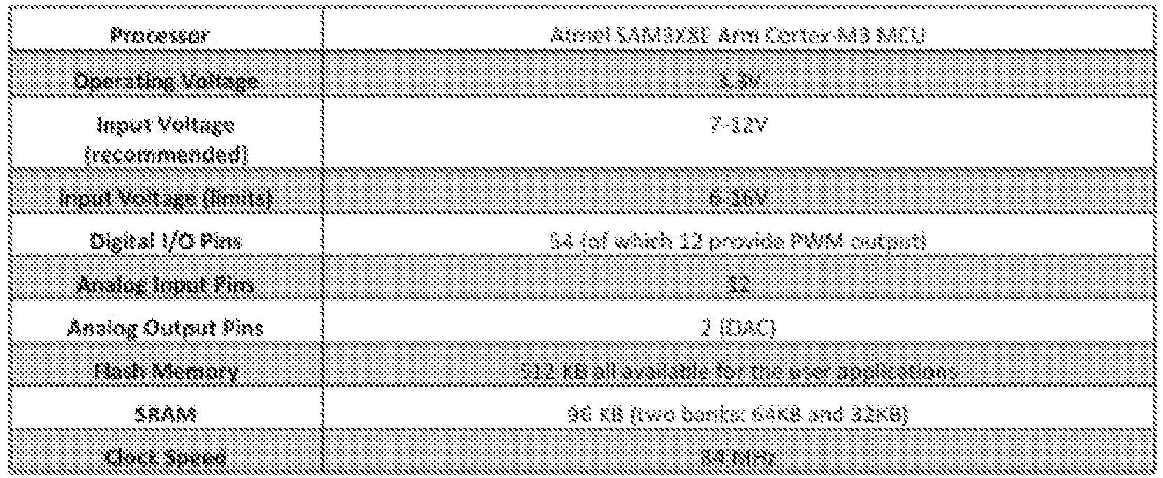
- the unit is based, for example, on the PC Due board with the following specifications:
- different communication modules can be used for interfacing with the supervision unit including, for example, XBEE, Ethernet SHIELD, Bluetooth, WIFI Shield and the like.
- the supply module is produced by means of three supply sub-modules, each of which being composed of an isolation transformer, a diode bridge, capacitors and a voltage regulator, used for supplying respectively:
- the main components of the supply modules are: - Isolation transformer: it allows the grid voltage to be transformed into a lower voltage.
- - Isolation transformer it allows the grid voltage to be transformed into a lower voltage.
- the device is also conceived and developed to record voltages lower than 230 VAC (sag and undervoltage), consequently the secondary side voltage must lie within the range of admissible voltages going into the voltage regulator in these particular cases, too. Consequently, possible isolation transformer choices are: PRIMARY ADMISSIBLE VOLTAGE SECONDARY ADMISSIBLE VOLTAGE ISOLATION TRANSFORMER 0 / 400 VAC 0 / 24 VAC ISOLATION TRANSFORMER 0 / 500 VAC 0 / 36 VAC
- the isolation transformer is "only" used for transforming the grid voltage into a lower voltage and not as a measurement transformer, it can be replaced with a simple voltage divider, opportunely dimensioned, so as to generate an output voltage, which lies within the input range of the voltage regulator.
- the resistances chosen must be able to withstand the voltage to which they are subjected without burning.
- the board shown in fig. 2 comprises the sensor ACS714 developed by Allegro Microsystems. It is a linear current sensor based on the Hall effect, which has a low resistance ( ⁇ 1.2m) of the electric circuit and galvanic isolation higher than 2.1 kV RMS. This version accepts a module bidirectional input current higher than 30 A and an output proportionate to the recorded current value, centered on 2.5 V if supplied at 5 V, centered at 1.65 V if supplied at 3.3 V, with a typical error of ⁇ 1.5%.
- the sensor works at 5V and has a sensitivity of 66 mV/A.
- the module is used for acquiring the single samples of the instant voltage. With reference to fig. 4 , it is composed of:
- the relay is a switch with one or more electrical contacts driven by an electromagnet when the coil of the same is crossed by a current.
- This relay is controlled by the control unit based on the signal sent by the user via the control platform and allows the load to be activated or disabled from the mains.
- electronic switches such as SCR and the like can also be used.
- the power factor correction circuit is made up of three relays arranged parallel connected to an equal number of correction capacitors, which are activated by the control unit.
- the power factor correction unit has two operating modes:
- the power factor correction circuit comprises a battery of capacitors, in parallel, which can be excluded individually by means of break devices arranged in series, such as relays, electronic switches or the like, driven by the control unit, to introduce a capacitive reactance into the supply circuit of the load, so as to compensate, at least partially, for the inductive reactance of the load, so as to take the power factor to values higher than 0.7, preferably higher than 0.8, typically higher than 0.9.
- the module is made up of various relays or electronic switches, which are activated by the control unit according to the signal sent from the control platform allowing the socket to be connected directly to the single commands of the electric load, for example they can be used for replacing/supporting the electromechanical buttons found in various household appliances, so as to operate a particular program depending on the needs.
- the socket can be included as part of a system for monitoring the operating parameters of one or more loads in a power grid.
- a system for monitoring the operating parameters of one or more loads in a power grid.
- Such system whose block diagram is shown in fig.5 , comprises one or more supervision units 3 interfaced with one or more smart sockets 1 for reading data related to the mains voltage and current drawn by the load (s) 2 when such smart socket (s) are inserted in series between the electric mains and the load.
- the supervision unit 3 can remotely control both the socket 1 and the load 2 connected thereto, creating a node of a Smart Grid network.
- control unit 901 of the socket 1 can receive command signals sent by the user through the communication module 201, so as to remotely control both the turning on/off of the socket via the load on/off relay 601 and the selection of a particular load program by means of the load interface relay module 801 and/or the digital and analog pins 901 of the control unit 101.
- the latter function remote program selection
- the system is able to perform Power Quality analyses.
- This term refers to a wide range of electromagnetic phenomena, which characterize the voltage and/or current in a given point of the electric system.
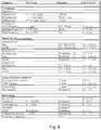
- the IEEE proposed a subdivision of the phenomena, the root of disturbances caused in the electrical systems as shown in the table in fig. 6 .
Description
- The invention relates to the sector of Smart Grids and Smart Metering within the scope of power grids.
- The term "Smart Grid" is understood to mean an infrastructure/network controlled smartly, so as to be able to manage the various power flows consciously and provide end users with competitive prices.
- Specifically, the ERGEG (Association of 27 European regulators) has formulated the following definition of "Smart Grid": "The Smart Grid is a power supply, which efficiently integrates and manages the conduct and action of all users connected to the power supply (generators, sampling points, and generation and sampling points) with the aim of guaranteeing a financially efficient operation of the electrical system, with low losses, an elevated level of safety and continuity and quality of the supply".
- A fundamental part of Smart Grids is Smart Metering, the object of which is to know consumption profiles in real time, thus giving power supply operators the right to create mechanisms provided with greater flexibility, dynamicity, offering customers, the energy consumers, a greater understanding and awareness of their consumptions. A fundamental requisite of Smart Meter is the possibility to record various users' consumption in real-time and send the remotely acquired data.
- Several devices are currently known, called smart sockets in jargon, which can measure electrical magnitudes, in particular grid voltage and current absorbed by the load. Although they carry out their role perfectly, they are nonetheless very specific devices able to process the values measured locally and provide broad indications regarding various electrical parameters, such as the power absorbed by the load, which can be used by the power supply operators to offer customers differentiated contracts based on the specific consumption characteristics. Furthermore, the Smart Grid requires sampling capacities and data processing, which go way beyond simple signal samplings and the relative processing. Document
CN204992153 discloses an example of multi -functional smart socket based on Wi -Fi interfacing and connection. DocumentUS2016/156225 discloses another example of multi -functional smart socket configured to provide real-time analysis of the main and connected loads. DocumentCN205543522 discloses yet another example of smart socket adapted to monitor active and reactive power to and from the mains network. - It is an object of the present invention to produce an improved smart socket and relative monitoring and system, which can be used within the scope of Smart Grids for actively managing power supply consumptions.
- The invention achieves the object with a smart socket according to
claim 1. - The socket is not limited to reading voltage and current data, but interacts strongly with the load thanks to the dialogue with one or more remote supervision units, which can read and process such data and send commands to control and optimize the working of the mains.
- In fact, the load control devices can comprise simple modules, which act on the load supply circuit, for example, using a break device for the current circulation on the load, such as a relay, an electronic switch or the like, or, combined, either a power factor correction circuit, which reduces the reactive power on the load, or combined, elements, which allow the control unit to interface with the load, so as to allow the control unit to set at least part of the relative operating parameters directly on the load.
- To this end, the control unit is advantageously configured to receive control signals from the supervision unit for remotely controlling the turning on/ off and, more generally, the working of the load, optimizing consumption or other performance indexes according to the operating parameters monitored.
- According to another aspect, the invention relates to a system according to claim 6.
- Advantageously, the supervision unit can be configured to process parameters from the smart socket(s) to provide an output Power Quality analysis of the mains.
- Further objects, characteristics and advantages of the present invention will become clearer from the following detailed description, given by way of example, which is not limiting, illustrated in the appended figures, wherein:
-
Fig. 1 shows a smart socket according to one embodiment of the invention. -
Fig. 2 shows an example of a current sensor usable in the socket according to the invention. -
Fig. 3 shows an example of a voltage generator of reference used in combination with the current sensor in the previous figure in an improvement of the invention. -
Fig. 4 shows the block diagram of a voltage recording module; -
Fig. 5 shows the block diagram of a monitoring and control system according to one embodiment of the invention. -
Fig. 6 reports a table with the Power Quality magnitudes, which can be measured with the system according to the invention. - With reference to the block diagram in
fig. 1 , in one embodiment of the invention, thesmart socket 1 comprises the following modules: a control unit 101, acommunication module 201, asupply module 301, acurrent sensor 401, avoltage recording module 501, a load on/offrelay 601, a powerfactor correction circuit 701, a relay module for interfacing towards theload 801 and possiblypins 901 for the direct connection between the load and the control unit. - The single components of the system will now be described.
- The unit is based, for example, on the Arduino Due board with the following specifications:
- Depending on the needs, different communication modules can be used for interfacing with the supervision unit including, for example, XBEE, Ethernet SHIELD, Bluetooth, WIFI Shield and the like.
- In an advantageous configuration, the supply module is produced by means of three supply sub-modules, each of which being composed of an isolation transformer, a diode bridge, capacitors and a voltage regulator, used for supplying respectively:
- the control unit;
- the load interface relay module;
- the power factor correction circuit;
- the load on/off relay.
- In particular, the main components of the supply modules are:
- Isolation transformer: it allows the grid voltage to be transformed into a lower voltage. When choosing the transformer, it is necessary to consider that the tolerable input voltage (primary side voltage) must be higher than 230 VAC (standard grid voltage), this is because the device is conceived and developed with the aim of being able to record voltages higher than 230 V working (overvoltage and swell) by means of the voltage recording module, consequently the choice of classical transformers at 230 VAC would prevent such aim from being reached, resulting in the destruction of the transformer, and consequently the interruption of the supply. Similarly, the device is also conceived and developed to record voltages lower than 230 VAC (sag and undervoltage), consequently the secondary side voltage must lie within the range of admissible voltages going into the voltage regulator in these particular cases, too. Consequently, possible isolation transformer choices are:PRIMARY ADMISSIBLE VOLTAGE SECONDARY ADMISSIBLE VOLTAGE ISOLATION TRANSFORMER 0 / 400 VAC 0 / 24 VAC ISOLATION TRANSFORMER 0 / 500 VAC 0 / 36 VAC - Also note that, as the isolation transformer is "only" used for transforming the grid voltage into a lower voltage and not as a measurement transformer, it can be replaced with a simple voltage divider, opportunely dimensioned, so as to generate an output voltage, which lies within the input range of the voltage regulator. Clearly, the resistances chosen must be able to withstand the voltage to which they are subjected without burning.
- Rectifier bridge: allows the voltage from the transformer and from the voltage divider to be rectified.
- Voltage regulator: allows the stabilization of the supply voltage going into the various modules. As the voltage coming out of the rectifier bridge will have an extremely wide range, it is necessary to use a voltage regulator with an equally wide interval of admissible input voltage values. For this reason, one possible choice of regulator is given by the step-down voltage regulator d24v3f5, which presents a wide range of admissible input voltage ranging from 7 to 42V.
- Capacitors: these are used to reduce the ripple and avoid possible spikes in voltage, which are potentially damaging to the regulator itself.
- The board shown in
fig. 2 comprises the sensor ACS714 developed by Allegro Microsystems. It is a linear current sensor based on the Hall effect, which has a low resistance (∼1.2m) of the electric circuit and galvanic isolation higher than 2.1 kV RMS. This version accepts a module bidirectional input current higher than 30 A and an output proportionate to the recorded current value, centered on 2.5 V if supplied at 5 V, centered at 1.65 V if supplied at 3.3 V, with a typical error of ±1.5%. The sensor works at 5V and has a sensitivity of 66 mV/A. - Such sensor was only used for financial reasons and, as can be seen from the brief description, besides not offering elevated precision, presents no internal circuit, which can compensate the offset. Also note how the sensor is conceived to work with input voltage equal to 5 VDC, however, the board used allows a maximum voltage on the analog pins equal to 3.3 V, therefore, the sensor ACS714 is supplied with such voltage. Such choice causes no significant increase in the measurement error.
- In fact, an integrated LM4132 3.3V, shown in
fig. 3 , was used to increase the precision of the measurement, so as to reduce possible fluctuations on the VCC pin of the sensor. - The optimal solution, for control units at tolerant 3.3V, is represented by the use of Hall effect current sensors, with supply voltage equal to 3.3v or, if sensors with a higher supply voltage are desired, it is advantageous to use either bidirectional logical level transducers 3.3V - 5V (in this case for VCC = 5 VDC), or adapt the output voltage, so that it is between 0 and 3.3 V, generally more refined, so as to provide more precise measurements, which can compensate any offset.
- The module is used for acquiring the single samples of the instant voltage. With reference to
fig. 4 , it is composed of: - Precision AC-AC transformer. The same transformers adopted for producing the supply modules cannot be used for the application since extremely elevated measurement precision is required, for this reason it is advantageous to use a voltage transformer with a precision class equal to 0.2. The same indications stated previously apply for the dimensioning of the transformer (primary side voltage).
- Sampling resistors, used for adapting the secondary side voltage of the transformer to the input voltage of the analog pins. Precision resistors (tolerance ≈ 1%) with a sufficiently small value (in the order of a few Ohms) are typically used to improve the precision of the measurement, this is because, as it is a voltage measurement, the impedance of the analog pin of the board must be much greater than the impedance of the resistance on which the measurement is taken.
- The relay is a switch with one or more electrical contacts driven by an electromagnet when the coil of the same is crossed by a current. This relay is controlled by the control unit based on the signal sent by the user via the control platform and allows the load to be activated or disabled from the mains. Naturally, electronic switches, such as SCR and the like can also be used.
- The power factor correction circuit is made up of three relays arranged parallel connected to an equal number of correction capacitors, which are activated by the control unit. The power factor correction unit has two operating modes:
- I mode: only the first two relays work, connected to an equal number of "fixed" correction capacitors (whose value cannot be modified), which are operated according to the phase recorded, so as to reduce it and lessen the reactive power and consequently increase both the efficiency and the useful life of the electric load connected to the socket;
- II mode: only the third relay works, connected to a correction capacitor chosen by the user, which is activated according to the phase recorded.
- More generally, the power factor correction circuit comprises a battery of capacitors, in parallel, which can be excluded individually by means of break devices arranged in series, such as relays, electronic switches or the like, driven by the control unit, to introduce a capacitive reactance into the supply circuit of the load, so as to compensate, at least partially, for the inductive reactance of the load, so as to take the power factor to values higher than 0.7, preferably higher than 0.8, typically higher than 0.9.
- The module is made up of various relays or electronic switches, which are activated by the control unit according to the signal sent from the control platform allowing the socket to be connected directly to the single commands of the electric load, for example they can be used for replacing/supporting the electromechanical buttons found in various household appliances, so as to operate a particular program depending on the needs.
- Advantageously, the socket can be included as part of a system for monitoring the operating parameters of one or more loads in a power grid. Such system, whose block diagram is shown in
fig.5 , comprises one ormore supervision units 3 interfaced with one or moresmart sockets 1 for reading data related to the mains voltage and current drawn by the load (s) 2 when such smart socket (s) are inserted in series between the electric mains and the load. Besides reading and processing the electrical data from thesocket 1, advantageously, thesupervision unit 3 can remotely control both thesocket 1 and theload 2 connected thereto, creating a node of a Smart Grid network. - Specifically, the
control unit 901 of thesocket 1 can receive command signals sent by the user through thecommunication module 201, so as to remotely control both the turning on/off of the socket via the load on/offrelay 601 and the selection of a particular load program by means of the loadinterface relay module 801 and/or the digital and analog pins 901 of the control unit 101. Clearly, the latter function (remote program selection), presupposes an invasive and personalized intervention for each load, involving the need to access the printed circuit board and/or the electromechanical buttons physically, all the more so if a direct interface is made between the control unit and the load itself by means of special pins, as shown infig. 1 . - By implementing such functionality, it is possible to achieve smart management of the electric load, so as to regulate its working, optimizing consumption or other performance indexes.
- With regard to the recorded parameters, the following table summarizes the possible measurements, which can be taken with the system according to the invention.

- As stated above, it is possible to implement the power factor correction of the
load 2 connected to thesocket 1 by means of the powerfactor correction circuit 701 in thesmart socket 1, so as to obtain multiple benefits: - a reduction in dissipated energy. In fact, a corrected load allows users to pay only for the energy effectively used. For example: In a load with inductive cosϕ=0.70, only 70% of the power supplied by the transformer in the cabin is used to produce useful work, while the rest serves to produce the reactive energy requested by the load and dispersed, in part, in the form of heat, by Joule effect;
- an increase in the power available on the supply systems;
- a reduction in voltage drops, with positive consequences on the working of users' equipment;
- a reduction in energy loss in the conductors caused by the reduced intensity of current in circulation at the same power.
- Advantageously, the system is able to perform Power Quality analyses. This term refers to a wide range of electromagnetic phenomena, which characterize the voltage and/or current in a given point of the electric system. By issuing the recommendations Std. 1159-1995, the IEEE proposed a subdivision of the phenomena, the root of disturbances caused in the electrical systems as shown in the table in
fig. 6 .
Claims (10)
- A smart socket (1) for monitoring electric operating parameters of a load, whereby the smart socket is inserted in series between the load and a mains network, comprising:at least one voltage sensor (501) and a current sensor (401) interfaced with a control unit (101) configured to read the electric mains voltage and drawn current values when the socket is inserted between the load and the mains network;a communication module (201) interfaced with the control unit (101) configured to send data and receive controls from a remote supervision unit (3);load control devices (601, 701, 801, 901) configured to operate according to the controls received from the communication module (201) and/or to the controls preset in the control unit (101);characterized in that the load control devices comprise a power factor correction circuit (701) comprising a battery of capacitors in parallel which can be excluded individually by means of break devices arranged in series, such as relays, electronic switches or the like, driven by the control unit (101) to introduce a capacitive reactance into the supply circuit of the load (2) so as to at least partially compensate for the inductive reactance of the load so as to take the power factor to values higher than 0.7, preferably higher than 0.8, typically higher than 0.9.
- A socket (1) according to claim 1, wherein the load control devices comprise modules (601) which act on the supply circuit of the load (2).
- A socket (1) according to claim 2, wherein the modules (601) which act on the supply of the load (2) comprise a break device of the current circulation on the load, such as a relay, an electronic switch or the like, driven by the control unit to turn the load on/off.
- A socket (1) according to one or more of the preceding claims, wherein the load control devices comprise elements (801, 901) which are configured to interface the control unit (101) with the load (2) so as to allow the control unit (101) to set at least part of the respective operating parameters directly on the load (2).
- A socket (1) according to one or more of the preceding claims, wherein the control unit (101) is configured to receive control signals from the supervision unit (3) for remotely turning on/off, and more in general controlling the operation of the load (2), thus optimizing consumption or other performance indexes according to the monitored operating parameters.
- A system for monitoring operating parameters of one or more loads present in a mains network, which system comprises one or more supervision units (3) interfaced with one or more smart sockets (1) according to one or more of the preceding claims in order to read data related to the electric mains voltage and current drawn by the load(s) (2) when such smart socket(s) (1) are inserted in series between the electric mains and the load.
- A system according to claim 6, wherein the supervision unit (3) interfaces with the smart socket(s) (1) by means of a wired or wireless network, particularly by means of Bluetooth, Wifi, Zigbee networks or the like.
- A system according to claim 6 or 7, wherein the supervision unit (3) is configured to read electric parameters by means of one or more smart sockets (1) and to process such parameters to output a Power Quality analysis of the mains network.
- A system according to claim 8, wherein the Power Quality analysis comprises processing one or more parameters selected from the list consisting of: effective voltage value, mean voltage value, maximum voltage value, minimum voltage value, effective current value, mean current value, maximum current value, minimum current value, power factor, active power, reactive power, apparent power.
- A system according to claim 8 or 9, wherein the Power Quality analysis comprises extrapolating one or more categories of electrical disturbances of the electric mains voltage chosen in the group consisting of: impulsive transients, oscillatory transients, instantaneous short duration variations, momentary short duration variations, temporary short duration variations, long duration variations, prolonged interruptions, undervoltages, overvoltages, dissimmetries, distortions due to DC offset, harmonic distortions, interharmonic distortions, notching distorsions, broadband noise distortions, voltage fluctuations distortions, frequency variation distortions.
Applications Claiming Priority (2)
| Application Number | Priority Date | Filing Date | Title |
|---|---|---|---|
| IT102016000123334A IT201600123334A1 (en) | 2016-12-05 | 2016-12-05 | Intelligent socket and monitoring and control system using this socket |
| PCT/IB2017/057634 WO2018104849A1 (en) | 2016-12-05 | 2017-12-05 | A smart socket and monitoring and control system using said socket |
Publications (2)
| Publication Number | Publication Date |
|---|---|
| EP3549227A1 EP3549227A1 (en) | 2019-10-09 |
| EP3549227B1 true EP3549227B1 (en) | 2021-10-27 |
Family
ID=58609760
Family Applications (1)
| Application Number | Title | Priority Date | Filing Date |
|---|---|---|---|
| EP17826279.6A Active EP3549227B1 (en) | 2016-12-05 | 2017-12-05 | A smart socket and monitoring and control system using said socket |
Country Status (4)
| Country | Link |
|---|---|
| US (1) | US20200153272A1 (en) |
| EP (1) | EP3549227B1 (en) |
| IT (1) | IT201600123334A1 (en) |
| WO (1) | WO2018104849A1 (en) |
Families Citing this family (7)
| Publication number | Priority date | Publication date | Assignee | Title |
|---|---|---|---|---|
| CN111064280A (en) * | 2019-12-16 | 2020-04-24 | 嵊州市法佳电器有限公司 | Wireless socket adjusted through pwm wave |
| IT201900025855A1 (en) | 2019-12-31 | 2021-07-01 | Univ Degli Studi Di Firenze | System for monitoring and analyzing electrical parameters |
| CN111541735A (en) * | 2020-03-12 | 2020-08-14 | 国网河北省电力有限公司雄安新区供电公司 | Direct-current self-adaptive port Internet of things system and control method thereof |
| US11894638B2 (en) * | 2020-07-27 | 2024-02-06 | Illinois Institute Of Technology | Solid state protective smart plug device |
| CN114142303B (en) * | 2021-12-02 | 2024-02-09 | 彭宇晨 | Smart jack, fire protection method and cloud server |
| CN116799572A (en) * | 2023-06-26 | 2023-09-22 | 南京惠派智慧后勤服务有限公司 | Energy-saving split air conditioner socket based on wireless network control |
| CN117375120B (en) * | 2023-12-07 | 2024-02-06 | 深圳市鼎阳科技股份有限公司 | Power supply and working method thereof |
Citations (3)
| Publication number | Priority date | Publication date | Assignee | Title |
|---|---|---|---|---|
| CN204992153U (en) * | 2015-07-28 | 2016-01-20 | 北京智芯微电子科技有限公司 | Multi -functional smart jack based on wi -Fi |
| US20160156225A1 (en) * | 2014-12-01 | 2016-06-02 | Eaton Corporation | Load power device and system for real-time execution of hierarchical load identification algorithms |
| CN205543522U (en) * | 2016-01-22 | 2016-08-31 | 浙江新再灵科技股份有限公司 | Smart jack that can not have consumption compensation voluntarily |
Family Cites Families (5)
| Publication number | Priority date | Publication date | Assignee | Title |
|---|---|---|---|---|
| US7795759B2 (en) * | 2008-06-27 | 2010-09-14 | iGo, Inc | Load condition controlled power strip |
| EP2529190A4 (en) * | 2010-01-25 | 2015-02-25 | Geneva Cleantech Inc | Automatic detection of appliances |
| US8583955B2 (en) * | 2011-10-04 | 2013-11-12 | Advanergy, Inc. | Battery management system and method |
| US8649883B2 (en) * | 2011-10-04 | 2014-02-11 | Advanergy, Inc. | Power distribution system and method |
| US8872390B2 (en) * | 2012-10-31 | 2014-10-28 | SSI America, Inc. | Wireless communication-enabled energy consumption monitor and mobile application for same |
-
2016
- 2016-12-05 IT IT102016000123334A patent/IT201600123334A1/en unknown
-
2017
- 2017-12-05 WO PCT/IB2017/057634 patent/WO2018104849A1/en active Application Filing
- 2017-12-05 EP EP17826279.6A patent/EP3549227B1/en active Active
- 2017-12-05 US US16/466,498 patent/US20200153272A1/en not_active Abandoned
Patent Citations (3)
| Publication number | Priority date | Publication date | Assignee | Title |
|---|---|---|---|---|
| US20160156225A1 (en) * | 2014-12-01 | 2016-06-02 | Eaton Corporation | Load power device and system for real-time execution of hierarchical load identification algorithms |
| CN204992153U (en) * | 2015-07-28 | 2016-01-20 | 北京智芯微电子科技有限公司 | Multi -functional smart jack based on wi -Fi |
| CN205543522U (en) * | 2016-01-22 | 2016-08-31 | 浙江新再灵科技股份有限公司 | Smart jack that can not have consumption compensation voluntarily |
Also Published As
| Publication number | Publication date |
|---|---|
| IT201600123334A1 (en) | 2018-06-05 |
| US20200153272A1 (en) | 2020-05-14 |
| EP3549227A1 (en) | 2019-10-09 |
| WO2018104849A1 (en) | 2018-06-14 |
Similar Documents
| Publication | Publication Date | Title |
|---|---|---|
| EP3549227B1 (en) | A smart socket and monitoring and control system using said socket | |
| US11043811B2 (en) | Reactive power control method, device and system | |
| US7573253B2 (en) | System for managing electrical consumption | |
| US7009379B2 (en) | Electricity meter with power supply load management | |
| KR20220062116A (en) | Systems and methods for managing electrical loads | |
| Uluski | VVC in the smart grid era | |
| US20120194146A1 (en) | Adaptive Control of Electrical Devices to Achieve Desired Power Use Characteristics | |
| JP6879912B2 (en) | How to optimize the consumption of dead power | |
| CN105723588A (en) | Uninterruptible power supply control | |
| US20110077878A1 (en) | Power supply with data communications | |
| US6384583B1 (en) | Power pod controller system | |
| JP6782442B2 (en) | Measuring equipment, measuring system and computer system | |
| US20100061028A1 (en) | System for managing electrical consumption with coaxial communication line protection | |
| US9859049B2 (en) | System for reducing electrical consumption with triple core iterative transformers | |
| KR101073809B1 (en) | Smart automatic standby power cut-off swithching apparatus | |
| KR102594678B1 (en) | Operation apparatus for substation and the control method thereof | |
| US20150256090A1 (en) | Systems for reducing electrical consumption using triple core iterative transformers | |
| US6448747B1 (en) | Electricity pod controller device | |
| US11239659B2 (en) | Microgrid autosynchronizing using remote recloser inputs and outputs | |
| CN204304602U (en) | Anti-electricity dazzling device | |
| Vani | Distribution and Load Sharing of Transformer Automatically by Using Microcontroller | |
| CN219554657U (en) | Lighting power distribution optimizing equipment | |
| US11921532B2 (en) | Controlling pulsed operation of a power supply during a power outage | |
| CN202817774U (en) | Low voltage power network reactive compensation telecontrol system | |
| Sedhuraman et al. | Performance Investigation of Smart Integrated Circuit Breaker Using Raspberry Pi and Arduino Controller |
Legal Events
| Date | Code | Title | Description |
|---|---|---|---|
| STAA | Information on the status of an ep patent application or granted ep patent |
Free format text: STATUS: UNKNOWN |
|
| STAA | Information on the status of an ep patent application or granted ep patent |
Free format text: STATUS: THE INTERNATIONAL PUBLICATION HAS BEEN MADE |
|
| PUAI | Public reference made under article 153(3) epc to a published international application that has entered the european phase |
Free format text: ORIGINAL CODE: 0009012 |
|
| STAA | Information on the status of an ep patent application or granted ep patent |
Free format text: STATUS: REQUEST FOR EXAMINATION WAS MADE |
|
| 17P | Request for examination filed |
Effective date: 20190702 |
|
| AK | Designated contracting states |
Kind code of ref document: A1 Designated state(s): AL AT BE BG CH CY CZ DE DK EE ES FI FR GB GR HR HU IE IS IT LI LT LU LV MC MK MT NL NO PL PT RO RS SE SI SK SM TR |
|
| AX | Request for extension of the european patent |
Extension state: BA ME |
|
| DAV | Request for validation of the european patent (deleted) | ||
| DAX | Request for extension of the european patent (deleted) | ||
| STAA | Information on the status of an ep patent application or granted ep patent |
Free format text: STATUS: EXAMINATION IS IN PROGRESS |
|
| 17Q | First examination report despatched |
Effective date: 20200610 |
|
| STAA | Information on the status of an ep patent application or granted ep patent |
Free format text: STATUS: EXAMINATION IS IN PROGRESS |
|
| GRAP | Despatch of communication of intention to grant a patent |
Free format text: ORIGINAL CODE: EPIDOSNIGR1 |
|
| STAA | Information on the status of an ep patent application or granted ep patent |
Free format text: STATUS: GRANT OF PATENT IS INTENDED |
|
| INTG | Intention to grant announced |
Effective date: 20210519 |
|
| GRAS | Grant fee paid |
Free format text: ORIGINAL CODE: EPIDOSNIGR3 |
|
| GRAA | (expected) grant |
Free format text: ORIGINAL CODE: 0009210 |
|
| STAA | Information on the status of an ep patent application or granted ep patent |
Free format text: STATUS: THE PATENT HAS BEEN GRANTED |
|
| AK | Designated contracting states |
Kind code of ref document: B1 Designated state(s): AL AT BE BG CH CY CZ DE DK EE ES FI FR GB GR HR HU IE IS IT LI LT LU LV MC MK MT NL NO PL PT RO RS SE SI SK SM TR |
|
| REG | Reference to a national code |
Ref country code: GB Ref legal event code: FG4D |
|
| REG | Reference to a national code |
Ref country code: CH Ref legal event code: EP |
|
| REG | Reference to a national code |
Ref country code: DE Ref legal event code: R096 Ref document number: 602017048406 Country of ref document: DE |
|
| REG | Reference to a national code |
Ref country code: AT Ref legal event code: REF Ref document number: 1442705 Country of ref document: AT Kind code of ref document: T Effective date: 20211115 |
|
| REG | Reference to a national code |
Ref country code: IE Ref legal event code: FG4D |
|
| REG | Reference to a national code |
Ref country code: LT Ref legal event code: MG9D |
|
| REG | Reference to a national code |
Ref country code: NL Ref legal event code: MP Effective date: 20211027 |
|
| REG | Reference to a national code |
Ref country code: AT Ref legal event code: MK05 Ref document number: 1442705 Country of ref document: AT Kind code of ref document: T Effective date: 20211027 |
|
| PG25 | Lapsed in a contracting state [announced via postgrant information from national office to epo] |
Ref country code: RS Free format text: LAPSE BECAUSE OF FAILURE TO SUBMIT A TRANSLATION OF THE DESCRIPTION OR TO PAY THE FEE WITHIN THE PRESCRIBED TIME-LIMIT Effective date: 20211027 Ref country code: LT Free format text: LAPSE BECAUSE OF FAILURE TO SUBMIT A TRANSLATION OF THE DESCRIPTION OR TO PAY THE FEE WITHIN THE PRESCRIBED TIME-LIMIT Effective date: 20211027 Ref country code: FI Free format text: LAPSE BECAUSE OF FAILURE TO SUBMIT A TRANSLATION OF THE DESCRIPTION OR TO PAY THE FEE WITHIN THE PRESCRIBED TIME-LIMIT Effective date: 20211027 Ref country code: BG Free format text: LAPSE BECAUSE OF FAILURE TO SUBMIT A TRANSLATION OF THE DESCRIPTION OR TO PAY THE FEE WITHIN THE PRESCRIBED TIME-LIMIT Effective date: 20220127 Ref country code: AT Free format text: LAPSE BECAUSE OF FAILURE TO SUBMIT A TRANSLATION OF THE DESCRIPTION OR TO PAY THE FEE WITHIN THE PRESCRIBED TIME-LIMIT Effective date: 20211027 |
|
| PG25 | Lapsed in a contracting state [announced via postgrant information from national office to epo] |
Ref country code: IS Free format text: LAPSE BECAUSE OF FAILURE TO SUBMIT A TRANSLATION OF THE DESCRIPTION OR TO PAY THE FEE WITHIN THE PRESCRIBED TIME-LIMIT Effective date: 20220227 Ref country code: SE Free format text: LAPSE BECAUSE OF FAILURE TO SUBMIT A TRANSLATION OF THE DESCRIPTION OR TO PAY THE FEE WITHIN THE PRESCRIBED TIME-LIMIT Effective date: 20211027 Ref country code: PT Free format text: LAPSE BECAUSE OF FAILURE TO SUBMIT A TRANSLATION OF THE DESCRIPTION OR TO PAY THE FEE WITHIN THE PRESCRIBED TIME-LIMIT Effective date: 20220228 Ref country code: PL Free format text: LAPSE BECAUSE OF FAILURE TO SUBMIT A TRANSLATION OF THE DESCRIPTION OR TO PAY THE FEE WITHIN THE PRESCRIBED TIME-LIMIT Effective date: 20211027 Ref country code: NO Free format text: LAPSE BECAUSE OF FAILURE TO SUBMIT A TRANSLATION OF THE DESCRIPTION OR TO PAY THE FEE WITHIN THE PRESCRIBED TIME-LIMIT Effective date: 20220127 Ref country code: NL Free format text: LAPSE BECAUSE OF FAILURE TO SUBMIT A TRANSLATION OF THE DESCRIPTION OR TO PAY THE FEE WITHIN THE PRESCRIBED TIME-LIMIT Effective date: 20211027 Ref country code: LV Free format text: LAPSE BECAUSE OF FAILURE TO SUBMIT A TRANSLATION OF THE DESCRIPTION OR TO PAY THE FEE WITHIN THE PRESCRIBED TIME-LIMIT Effective date: 20211027 Ref country code: HR Free format text: LAPSE BECAUSE OF FAILURE TO SUBMIT A TRANSLATION OF THE DESCRIPTION OR TO PAY THE FEE WITHIN THE PRESCRIBED TIME-LIMIT Effective date: 20211027 Ref country code: GR Free format text: LAPSE BECAUSE OF FAILURE TO SUBMIT A TRANSLATION OF THE DESCRIPTION OR TO PAY THE FEE WITHIN THE PRESCRIBED TIME-LIMIT Effective date: 20220128 Ref country code: ES Free format text: LAPSE BECAUSE OF FAILURE TO SUBMIT A TRANSLATION OF THE DESCRIPTION OR TO PAY THE FEE WITHIN THE PRESCRIBED TIME-LIMIT Effective date: 20211027 |
|
| REG | Reference to a national code |
Ref country code: DE Ref legal event code: R097 Ref document number: 602017048406 Country of ref document: DE |
|
| PG25 | Lapsed in a contracting state [announced via postgrant information from national office to epo] |
Ref country code: SM Free format text: LAPSE BECAUSE OF FAILURE TO SUBMIT A TRANSLATION OF THE DESCRIPTION OR TO PAY THE FEE WITHIN THE PRESCRIBED TIME-LIMIT Effective date: 20211027 Ref country code: SK Free format text: LAPSE BECAUSE OF FAILURE TO SUBMIT A TRANSLATION OF THE DESCRIPTION OR TO PAY THE FEE WITHIN THE PRESCRIBED TIME-LIMIT Effective date: 20211027 Ref country code: RO Free format text: LAPSE BECAUSE OF FAILURE TO SUBMIT A TRANSLATION OF THE DESCRIPTION OR TO PAY THE FEE WITHIN THE PRESCRIBED TIME-LIMIT Effective date: 20211027 Ref country code: MC Free format text: LAPSE BECAUSE OF FAILURE TO SUBMIT A TRANSLATION OF THE DESCRIPTION OR TO PAY THE FEE WITHIN THE PRESCRIBED TIME-LIMIT Effective date: 20211027 Ref country code: EE Free format text: LAPSE BECAUSE OF FAILURE TO SUBMIT A TRANSLATION OF THE DESCRIPTION OR TO PAY THE FEE WITHIN THE PRESCRIBED TIME-LIMIT Effective date: 20211027 Ref country code: DK Free format text: LAPSE BECAUSE OF FAILURE TO SUBMIT A TRANSLATION OF THE DESCRIPTION OR TO PAY THE FEE WITHIN THE PRESCRIBED TIME-LIMIT Effective date: 20211027 Ref country code: CZ Free format text: LAPSE BECAUSE OF FAILURE TO SUBMIT A TRANSLATION OF THE DESCRIPTION OR TO PAY THE FEE WITHIN THE PRESCRIBED TIME-LIMIT Effective date: 20211027 |
|
| PLBE | No opposition filed within time limit |
Free format text: ORIGINAL CODE: 0009261 |
|
| STAA | Information on the status of an ep patent application or granted ep patent |
Free format text: STATUS: NO OPPOSITION FILED WITHIN TIME LIMIT |
|
| REG | Reference to a national code |
Ref country code: BE Ref legal event code: MM Effective date: 20211231 |
|
| 26N | No opposition filed |
Effective date: 20220728 |
|
| PG25 | Lapsed in a contracting state [announced via postgrant information from national office to epo] |
Ref country code: LU Free format text: LAPSE BECAUSE OF NON-PAYMENT OF DUE FEES Effective date: 20211205 Ref country code: IE Free format text: LAPSE BECAUSE OF NON-PAYMENT OF DUE FEES Effective date: 20211205 Ref country code: AL Free format text: LAPSE BECAUSE OF FAILURE TO SUBMIT A TRANSLATION OF THE DESCRIPTION OR TO PAY THE FEE WITHIN THE PRESCRIBED TIME-LIMIT Effective date: 20211027 |
|
| PG25 | Lapsed in a contracting state [announced via postgrant information from national office to epo] |
Ref country code: SI Free format text: LAPSE BECAUSE OF FAILURE TO SUBMIT A TRANSLATION OF THE DESCRIPTION OR TO PAY THE FEE WITHIN THE PRESCRIBED TIME-LIMIT Effective date: 20211027 Ref country code: BE Free format text: LAPSE BECAUSE OF NON-PAYMENT OF DUE FEES Effective date: 20211231 |
|
| PGFP | Annual fee paid to national office [announced via postgrant information from national office to epo] |
Ref country code: CH Payment date: 20230101 Year of fee payment: 6 |
|
| PG25 | Lapsed in a contracting state [announced via postgrant information from national office to epo] |
Ref country code: CY Free format text: LAPSE BECAUSE OF FAILURE TO SUBMIT A TRANSLATION OF THE DESCRIPTION OR TO PAY THE FEE WITHIN THE PRESCRIBED TIME-LIMIT Effective date: 20211027 |
|
| PG25 | Lapsed in a contracting state [announced via postgrant information from national office to epo] |
Ref country code: HU Free format text: LAPSE BECAUSE OF FAILURE TO SUBMIT A TRANSLATION OF THE DESCRIPTION OR TO PAY THE FEE WITHIN THE PRESCRIBED TIME-LIMIT; INVALID AB INITIO Effective date: 20171205 |
|
| PGFP | Annual fee paid to national office [announced via postgrant information from national office to epo] |
Ref country code: FR Payment date: 20230929 Year of fee payment: 7 |
|
| PGFP | Annual fee paid to national office [announced via postgrant information from national office to epo] |
Ref country code: GB Payment date: 20231012 Year of fee payment: 7 |
|
| PGFP | Annual fee paid to national office [announced via postgrant information from national office to epo] |
Ref country code: IT Payment date: 20231127 Year of fee payment: 7 Ref country code: DE Payment date: 20231010 Year of fee payment: 7 |