EP3548941B1 - Multi-waveguide light field display - Google Patents
Multi-waveguide light field display Download PDFInfo
- Publication number
- EP3548941B1 EP3548941B1 EP17876076.5A EP17876076A EP3548941B1 EP 3548941 B1 EP3548941 B1 EP 3548941B1 EP 17876076 A EP17876076 A EP 17876076A EP 3548941 B1 EP3548941 B1 EP 3548941B1
- Authority
- EP
- European Patent Office
- Prior art keywords
- waveguide
- substrate
- layer
- refraction
- patterned layer
- Prior art date
- Legal status (The legal status is an assumption and is not a legal conclusion. Google has not performed a legal analysis and makes no representation as to the accuracy of the status listed.)
- Active
Links
Images

Classifications
-
- G—PHYSICS
- G02—OPTICS
- G02B—OPTICAL ELEMENTS, SYSTEMS OR APPARATUS
- G02B1/00—Optical elements characterised by the material of which they are made; Optical coatings for optical elements
- G02B1/10—Optical coatings produced by application to, or surface treatment of, optical elements
- G02B1/11—Anti-reflection coatings
-
- G—PHYSICS
- G02—OPTICS
- G02B—OPTICAL ELEMENTS, SYSTEMS OR APPARATUS
- G02B27/00—Optical systems or apparatus not provided for by any of the groups G02B1/00 - G02B26/00, G02B30/00
- G02B27/01—Head-up displays
- G02B27/0101—Head-up displays characterised by optical features
-
- G—PHYSICS
- G02—OPTICS
- G02B—OPTICAL ELEMENTS, SYSTEMS OR APPARATUS
- G02B27/00—Optical systems or apparatus not provided for by any of the groups G02B1/00 - G02B26/00, G02B30/00
- G02B27/01—Head-up displays
- G02B27/017—Head mounted
- G02B27/0172—Head mounted characterised by optical features
-
- G—PHYSICS
- G02—OPTICS
- G02B—OPTICAL ELEMENTS, SYSTEMS OR APPARATUS
- G02B5/00—Optical elements other than lenses
- G02B5/18—Diffraction gratings
- G02B5/1842—Gratings for image generation
-
- G—PHYSICS
- G02—OPTICS
- G02B—OPTICAL ELEMENTS, SYSTEMS OR APPARATUS
- G02B6/00—Light guides; Structural details of arrangements comprising light guides and other optical elements, e.g. couplings
- G02B6/0001—Light guides; Structural details of arrangements comprising light guides and other optical elements, e.g. couplings specially adapted for lighting devices or systems
- G02B6/0011—Light guides; Structural details of arrangements comprising light guides and other optical elements, e.g. couplings specially adapted for lighting devices or systems the light guides being planar or of plate-like form
- G02B6/0033—Means for improving the coupling-out of light from the light guide
- G02B6/0035—Means for improving the coupling-out of light from the light guide provided on the surface of the light guide or in the bulk of it
- G02B6/0038—Linear indentations or grooves, e.g. arc-shaped grooves or meandering grooves, extending over the full length or width of the light guide
-
- G—PHYSICS
- G02—OPTICS
- G02B—OPTICAL ELEMENTS, SYSTEMS OR APPARATUS
- G02B6/00—Light guides; Structural details of arrangements comprising light guides and other optical elements, e.g. couplings
- G02B6/0001—Light guides; Structural details of arrangements comprising light guides and other optical elements, e.g. couplings specially adapted for lighting devices or systems
- G02B6/0011—Light guides; Structural details of arrangements comprising light guides and other optical elements, e.g. couplings specially adapted for lighting devices or systems the light guides being planar or of plate-like form
- G02B6/0065—Manufacturing aspects; Material aspects
-
- G—PHYSICS
- G02—OPTICS
- G02B—OPTICAL ELEMENTS, SYSTEMS OR APPARATUS
- G02B6/00—Light guides; Structural details of arrangements comprising light guides and other optical elements, e.g. couplings
- G02B6/0001—Light guides; Structural details of arrangements comprising light guides and other optical elements, e.g. couplings specially adapted for lighting devices or systems
- G02B6/0011—Light guides; Structural details of arrangements comprising light guides and other optical elements, e.g. couplings specially adapted for lighting devices or systems the light guides being planar or of plate-like form
- G02B6/0075—Arrangements of multiple light guides
- G02B6/0076—Stacked arrangements of multiple light guides of the same or different cross-sectional area
-
- G—PHYSICS
- G02—OPTICS
- G02B—OPTICAL ELEMENTS, SYSTEMS OR APPARATUS
- G02B6/00—Light guides; Structural details of arrangements comprising light guides and other optical elements, e.g. couplings
- G02B6/10—Light guides; Structural details of arrangements comprising light guides and other optical elements, e.g. couplings of the optical waveguide type
- G02B6/12—Light guides; Structural details of arrangements comprising light guides and other optical elements, e.g. couplings of the optical waveguide type of the integrated circuit kind
- G02B6/12007—Light guides; Structural details of arrangements comprising light guides and other optical elements, e.g. couplings of the optical waveguide type of the integrated circuit kind forming wavelength selective elements, e.g. multiplexer, demultiplexer
-
- G—PHYSICS
- G02—OPTICS
- G02B—OPTICAL ELEMENTS, SYSTEMS OR APPARATUS
- G02B27/00—Optical systems or apparatus not provided for by any of the groups G02B1/00 - G02B26/00, G02B30/00
- G02B27/42—Diffraction optics, i.e. systems including a diffractive element being designed for providing a diffractive effect
- G02B27/4205—Diffraction optics, i.e. systems including a diffractive element being designed for providing a diffractive effect having a diffractive optical element [DOE] contributing to image formation, e.g. whereby modulation transfer function MTF or optical aberrations are relevant
-
- G—PHYSICS
- G02—OPTICS
- G02B—OPTICAL ELEMENTS, SYSTEMS OR APPARATUS
- G02B27/00—Optical systems or apparatus not provided for by any of the groups G02B1/00 - G02B26/00, G02B30/00
- G02B27/42—Diffraction optics, i.e. systems including a diffractive element being designed for providing a diffractive effect
- G02B27/4272—Diffraction optics, i.e. systems including a diffractive element being designed for providing a diffractive effect having plural diffractive elements positioned sequentially along the optical path
Definitions
- This invention relates to waveguide displays, and multi-waveguide optical structures.
- Diffraction gratings are optical components with periodic structures that can split and diffract light into several beams travelling into different directions. The directions of these beams depend on the spacing of the grating and the wavelength of the light.
- a diffraction grating is made up of a set of slots with a spacing wider than the wavelength of the light to cause diffraction. After the light interacts with the grating, the diffracted light is composed of the sum of interfering waves emanating from each slot in the grating. Depths of the slots affect the path length of the waves to each slot, which accordingly affect the phases of the waves from each of the slots and thus the diffractive efficiencies of the slots. If the slots have a uniform depth, the slots in the grating may have a uniform diffractive efficiency. If the slots have non-uniform depths, the slots in the grating may have non-uniform diffractive efficiencies.
- US2016/216416 discloses a multi-waveguide optical structure with each waveguide having a substrate, a patterned layer, and an adhesive layer.
- a multi-waveguide optical structure as claimed in independent claim 1, including multiple waveguides stacked to intercept light passing sequentially through each waveguide, each waveguide associated with a differing color and a differing depth of plane, each waveguide including a first adhesive layer, a substrate having a first index of refraction, and a patterned layer positioned such that the first adhesive layer is between the patterned layer and the substrate, the first adhesive layer providing adhesion between the patterned layer and the substrate, the patterned layer having a second index of refraction less than the first index of refraction, the patterned layer defining a diffraction grating, wherein a field of view associated with the waveguide is based on the first and the second indices of refraction.
- Each waveguide further comprises a second adhesive layer positioned such that the substrate is between the first adhesive layer and the second adhesive layer.
- a waveguide support connecting and positioning each of the multiple waveguides, with at least one of the first and second adhesive layers of each waveguide adhering to the waveguide support.
- Each waveguide further comprises an anti-reflective layer positioned between the substrate and the second adhesive layer.
- Each waveguide further comprises an additional patterned layer positioned such that the second adhesive layer is positioned between the substrate and the additional patterned layer.
- the substrate is made of glass or sapphire.
- the field of view of each waveguide is at least 50 degrees.
- the first index of refraction is approximately 1.5 and the second index of refraction is at least 1.7.
- the patterned layer includes a residual layer thickness of less than 50 nanometers.
- a multi-waveguide optical structure including multiple waveguides stacked to intercept light passing sequentially through each waveguide, each waveguide associated with a differing color and a differing depth of plane, each waveguide including a first adhesive layer, an anti-reflective layer, a substrate positioned between the first adhesive layer and the anti-reflective layer, the substrate having a first index of refraction, a first patterned layer positioned such that the first adhesive layer is between the first patterned layer and the substrate, the first adhesive layer providing adhesion between the first patterned layer and the substrate, the first patterned layer having a second index of refraction less than the first index of refraction, the first patterned layer defining a diffraction grating, wherein a field of view associated with the waveguide is based on the first and the second indices of refraction, a second adhesive layer, and a second patterned layer positioned such that the second adhesive layer is positioned between the anti-reflective layer and the second
- each waveguide may include multiple waveguides stacked to intercept light passing sequentially through each waveguide, each waveguide associated with a differing color and a differing depth of plane, each waveguide including a first adhesive layer, an anti-reflective layer, a substrate positioned between the first adhesive layer and the anti-reflective layer, the substrate having a first index of refraction, a patterned layer positioned such that the first adhesive layer is between the patterned layer and the substrate, the first adhesive layer providing adhesion between the patterned layer and the substrate, the patterned layer having a second index of refraction less than the first index of refraction, the patterned layer defining a diffraction grating, wherein a field of view associated with the waveguide is based on the first and the second indices of refraction, and a second adhesive layer positioned such that the anti-reflective layer is positioned between the second adhesive layer and the substrate; and a waveguide support connecting and positioning each of the multiple waveguides, with at least one
- Implementations of the present disclosure may abrogate the need for etching of a glass (or sapphire) substrate to form diffraction gratings.
- the present disclosure enables simpler, higher volume processing of highly efficient diffraction waveguide displays that also exhibit enhanced environmental stability and benefits for building multi-waveguide light field displays while lowering manufacturing costs.
- the present disclosure provides formation of a composite material structure of the waveguide that is both optically efficient and lower cost versus traditional methods of formation.
- the multi-waveguide optical structure includes multiple waveguides stacked to intercept light passing sequentially through each waveguide.
- Each waveguide is associated with a differing color and a differing depth of plane.
- each waveguide is associated with a first adhesive layer, a substrate having a first index of refraction, and a patterned layer positioned such that the first adhesive layer is between the patterned layer and the substrate.
- the first adhesive layer provides adhesion between the patterned layer and the substrate.
- the patterned layer has a second index of refraction less than the first index of refraction and defines a diffraction grating.
- a field of view associated with the waveguide is based on the first and the second indices of refraction.
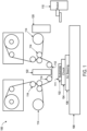
- FIG. 1 illustrates an imprint lithography system 100 that forms a relief pattern on a substrate 102.
- the substrate 102 may be coupled to a substrate chuck 104.
- the substrate chuck 104 can include a vacuum chuck, a pin-type chuck, a groove-type chuck, an electromagnetic chuck, and/or the like.
- the substrate 102 and the substrate chuck 104 may be further positioned on an air bearing 106.
- the air bearing 106 provides motion about the x-, y-, and/or z-axes.
- the substrate 102 and the substrate chuck 104 are positioned on a stage.
- the air bearing 106, the substrate 102, and the substrate chuck 104 may also be positioned on a base 108.
- a robotic system 110 positions the substrate 102 on the substrate chuck 104.
- the imprint lithography system 100 further includes an imprint lithography flexible template 112 that is coupled to one or more rollers 114, depending on design considerations.
- the rollers 114 provide movement of a least a portion of the flexible template 112. Such movement may selectively provide different portions of the flexible template 112 in superimposition with the substrate 102.
- the flexible template 112 includes a patterning surface that includes a plurality of features, e.g., spaced-apart recesses and protrusions. However, in some examples, other configurations of features are possible.
- the patterning surface may define any original pattern that forms the basis of a pattern to be formed on substrate 102.
- the flexible template 112 may be coupled to a template chuck, e.g., a vacuum chuck, a pin-type chuck, a groove-type chuck, an electromagnetic chuck, and/or the like.
- the imprint lithography system 100 may further comprise a fluid dispense system 120.
- the fluid dispense system 120 may be used to deposit a polymerizable material on the substrate 102.
- the polymerizable material may be positioned upon the substrate 102 using techniques such as drop dispense, spin-coating, dip coating, chemical vapor deposition (CVD), physical vapor deposition (PVD), thin film deposition, thick film deposition, and/or the like.
- the polymerizable material is positioned upon the substrate 102 as a plurality of droplets.
- the imprint lithography system 100 may further comprise an energy source 122 coupled to direct energy towards the substrate 102.
- the rollers 114 and the air bearing 106 are configured to position a desired portion of the flexible template 112 and the substrate 102 in a desired positioning.
- the imprint lithography system 100 may be regulated by a processor in communication with the air bearing 106, the rollers 114, the fluid dispense system 120, and/or the energy source 122, and may operate on a computer readable program stored in a memory.
- the rollers 114, the air bearing 106, or both vary a distance between the flexible template 112 and the substrate 102 to define a desired volume therebetween that is filled by the polymerizable material.
- the flexible template 112 contacts the polymerizable material.
- the energy source 122 produces energy, e.g., broadband ultraviolet radiation, causing the polymerizable material to solidify and/or cross-link conforming to shape of a surface of the substrate 102 and a portion of the patterning surface of the flexible template 122, defining a patterned layer 150 on the substrate 102.
- the patterned layer 150 may comprise a residual layer 152 and a plurality of features shown as protrusions 154 and recessions 156.
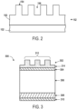
- FIG. 3 illustrates a waveguide 300 that may be formed utilizing the imprint lithography system 100.
- the waveguide 300 intercepts light passing therethrough, e.g ., from a source of light (light beam), and provides total internal refraction of the light.
- the waveguide 300 facilitates the generation of a virtual content display.
- the waveguide 300 is a multi-layered structure that includes a patterned layer 302, a first adhesive layer 304, a substrate 306, an anti-reflective layer 308, and a second adhesive layer 310.
- the substrate 306 is positioned between the first adhesive layer 304 and the anti-reflective layer 308.
- the substrate 306 is associated with a first index of refraction, and in some examples, is made of glass or sapphire. In some examples, the first index of refraction is at least 1.7 or greater.
- the first adhesive layer 304 provides adhesion between the patterned layer 302 and the substrate 306.
- the first adhesive layer 304 can be made of such materials as acrylated resin.
- the patterned layer 302 is positioned such that the first adhesive layer 304 is between the patterned layer 302 and the substrate 306.
- the patterned layer 302 can include a photo-cured acrylic polymer layer.
- the patterned layer 302 is associated with a second index of refraction. In some examples, the first index of refraction is greater than the second index of refraction. In some examples, the second index of refraction is approximately 1.5.
- the patterned layer 302 further includes diffraction gratings 312 and a residual layer 314. In some examples, the residual layer 314 has a thickness less than 100 nanometers, and further, in some examples, less than 50 nanometers.
- the diffraction gratings 312 can be formed by such methods including imprint lithography, and can include a critical dimension of approximately 100 nanometers.
- the waveguide 300 can define a diffraction-based waveguide display.
- the combination of the patterned layer 302 and the substrate 306, and specifically, the combination of the patterned layer 302 associated with the second index of refraction (e.g ., approximately 1.5) and the substrate 306 associated with the first index of refraction ( e.g ., greater than 1.7) provides the diffraction-based waveguide display.
- the diffraction-based waveguide display is provided without forming diffraction gratings in the substrate 306 as a result of forming the diffraction-based waveguide display based on the combination of the patterned layer 302 associated with the second index of refraction (e.g ., approximately 1.5) and the substrate 306 associated with the first index of refraction ( e.g ., greater than 1.7).
- the need to dry etch the substrate 306 e.g. , dry etch high-index glass or sapphire
- the substrate 306 can be partially etched (e.g., a plasma process under atmospheric or low pressure conditions) to remove the residual layer 134 and/or transfer the pattern into the substrate 306, while maintaining a portion of the residual layer 314 on a surface of the substrate 306.
- partially etched e.g., a plasma process under atmospheric or low pressure conditions
- the residual layer 314 having a thickness less than 100 nanometers, or less than 50 nanometers, refractive index matching between the patterned layer 302 and the substrate 306 is reduced, or minimized.
- the waveguide 300 is associated with a field of view based on the first and the second indices of refraction. That is, the field of view of the waveguide 300 is based on the combination of the second index of refraction associated with the patterned layer 302 and the first index of refraction associated with the substrate 306. In some examples, the field of view of the waveguide 300 is at least 50 degrees. That is, when the second index of refraction associated with the patterned layer 302 is approximately 1.5, and the first index of refraction associated with the substrate 306 is greater than 1.7, the field of view associated with the waveguide 300 is at least 50 degrees.
- the anti-reflective layer 308 is positioned between the substrate 306 and the second adhesive layer 310.
- the anti-reflective layer 308 is inorganic.
- the anti-reflective layer 308 and/or the patterned layer 302 provide environment protection/stability to the substrate 306.
- the substrate 306 includes glass (or sapphire) with a high-index ( e.g ., greater than 1.7)
- the substrate 306 when exposed to the environment, can form precipitants at a surface of the substrate 306.
- a haze contamination layer can form, ( e.g. , on the surface of the substrate 306)
- corrosion of the substrate 302 can form, and/or scattered light associated with the waveguide 300 can increase.
- the anti-reflective layer 308 and/or the patterned layer 302 isolate the ionic surface of the substrate 306 (e.g ., ionic surface of glass substrate), providing the environmental protection/stability of the substrate 306.
- the second adhesion layer 310 provides adhesion between the anti-reflective layer 308 and the substrate 306.
- the second adhesion layer 310 is vapor deposited and bonded to the substrate 306 (e.g., glass).
- the second adhesive layer 310 can be made of such materials as acrylated resin.
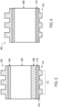
- FIG. 4 illustrates a multi-waveguide optical structure 400 including multiple waveguides 402a, 402b, 402c (collectively referred to as waveguides 402) stacked to intercept light passing sequentially through each waveguide 402.
- Each of the waveguides 402 can be similar to the waveguide 302 of FIG. 3 .
- each of the waveguides 402 is associated with a differing color and a differing depth of plane. That is, as light passes through each of the waveguides 402, each of the waveguides 402 interacts with the light differently, and each exiting light of the waveguide 402 is based on a differing color and a differing depth of plane associated with the virtual content display.
- the multi-waveguide optical structure 400 includes greater than three waveguides 402, including six or nine waveguides 402.
- each of the waveguides 402 of the multi-waveguide optical structure 400 is separated by air.
- the multi-waveguide optical structure 400 includes waveguide supports 404a, 404b (collectively referred to as waveguide supports 404).
- the waveguide supports 404 connect and position the multiple waveguides 402 within the multi-waveguide optical structure 400.
- the first adhesive layer 304 and the second adhesive layer 310 of each of the waveguides 402 provide adhesion between the respective waveguide 402 and the waveguide supports 404.
- the waveguide supports 404 can be made of such materials as acrylated resin or epoxy resin.
- the patterned layer 302 provides additional bonding between the respective waveguide 402 and the waveguide supports 404.
- FIG. 5 illustrates a waveguide 500 including an additional patterned layer.
- the waveguide 500 includes a first patterned layer 502, a first adhesive layer 504, a substrate 506, an anti-reflective layer 508, a second adhesive layer 510, and a second patterned layer 512.
- the first patterned layer 502, the first adhesive layer 504, the substrate 506, the anti-reflective layer 508, and the second adhesive layer 510 are substantially similar as the patterned layer 302, the first adhesive layer 304, the substrate 306, the anti-reflective layer 308, and the second adhesive layer 310 of the waveguide 300 of FIG. 3 .
- the second patterned layer 512 is positioned such that the second adhesive layer 510 is positioned between the anti-reflective layer 508 and the second patterned layer 512.
- the second adhesive layer 510 provides adhesion between the second patterned layer 512 and the substrate 506.
- a waveguide 500' is absent the anti-reflective layer 508, and thus, includes the second patterned layer 512 such that second adhesive layer 510 is positioned between the substrate 506 and the second patterned layer 512.
- the second patterned layer 512 is substantially similar to the patterned layer 302 of FIG. 3 . Specifically, the second patterned layer 512 is associated with a third index of refraction. In some examples, the first index of refraction associated with the substrate 506 is greater than the third index of refraction associated with the second patterned layer 512. In some examples, the third index of refraction is approximately 1.5.
- the second patterned layer 512 further includes diffraction gratings 514 and a residual layer 516 having a thickness less than 50 nanometers.
- the diffraction gratings 514 can be formed by such methods including imprint lithography, and can include a critical dimension of approximately 100 nanometers.
- the waveguide 500 can define a diffraction-based waveguide display.
- the combination of the second patterned layer 512 and the substrate 506, and specifically, the combination of the second patterned layer 512 associated with the third index of refraction (e.g., approximately 1.5) and the substrate 506 associated with the first index of refraction (e.g., greater than 1.7) provides a diffraction-based waveguide display.
- the diffraction-based waveguide display is provided without forming diffraction gratings in the substrate 506 as a result of forming the diffraction-based waveguide display based on the combination of the second patterned layer 512 associated with the third index of refraction (e.g., approximately 1.5) and the substrate 506 associated with the first index of refraction (e.g., greater than 1.7).
- the need to dry etch the substrate 506 e.g., dry etch high-index glass or sapphire
- the combination of the first patterned layer 502, the second patterned layer 512, and the substrate 506, and specifically, the combination of the first patterned layer 502 associated with the first index of refraction (e.g., approximately 1.5), the second patterned layer 512 associated with the third index of refraction ( e.g. , approximately 1.5), and the substrate 506 associated with the first index of refraction ( e.g ., greater than 1.7) provides the diffraction-based waveguide display.
- the waveguide 500 is associated with a field of view based on the first and the third indices of refraction. That is, the field of view of the waveguide 500 is based on the combination of the third index of refraction associated with the second patterned layer 512 and the first index of refraction associated with the substrate 506. In some examples, the field of view of the waveguide 500 is at least 50 degrees. That is, when the third index of refraction associated with the second patterned layer 512 is approximately 1.5, and the first index of refraction associated with the substrate 506 is greater than 1.7, the field of view associated with the waveguide 500 is at least 50 degrees.
- the field of view of the waveguide 500 is based on the combination of the second index of refraction associated with the first patterned layer 502, the third index of refraction associated with the second patterned layer 512 and the first index of refraction associated with the substrate 506.
- each of the waveguides 402 of the multi-waveguide optical structure 400 of FIG. 4 can be similar to the waveguide 500 of FIG. 5 and/or the waveguide 500' of FIG. 6 .
- the waveguides 402 of the multi-waveguide optical structure 400 can be similar to any combination of the waveguide 300 of FIG. 3 , the waveguide 500 of FIG. 5 , and the waveguide 500' of FIG. 6 .
- the imprint lithography system 100 of FIG. 1 can be used to form any of the waveguides 302, 402, 500, 500' and/or the multi-waveguide optical structure 400.
Landscapes
- Physics & Mathematics (AREA)
- General Physics & Mathematics (AREA)
- Optics & Photonics (AREA)
- Engineering & Computer Science (AREA)
- Manufacturing & Machinery (AREA)
- Microelectronics & Electronic Packaging (AREA)
- Optical Integrated Circuits (AREA)
- Diffracting Gratings Or Hologram Optical Elements (AREA)
Applications Claiming Priority (2)
| Application Number | Priority Date | Filing Date | Title |
|---|---|---|---|
| US201662428193P | 2016-11-30 | 2016-11-30 | |
| PCT/US2017/051796 WO2018102005A1 (en) | 2016-11-30 | 2017-09-15 | Multi-waveguide light field display |
Publications (3)
| Publication Number | Publication Date |
|---|---|
| EP3548941A1 EP3548941A1 (en) | 2019-10-09 |
| EP3548941A4 EP3548941A4 (en) | 2019-12-18 |
| EP3548941B1 true EP3548941B1 (en) | 2025-02-12 |
Family
ID=62189986
Family Applications (1)
| Application Number | Title | Priority Date | Filing Date |
|---|---|---|---|
| EP17876076.5A Active EP3548941B1 (en) | 2016-11-30 | 2017-09-15 | Multi-waveguide light field display |
Country Status (9)
| Country | Link |
|---|---|
| US (3) | US10444422B2 (enExample) |
| EP (1) | EP3548941B1 (enExample) |
| JP (1) | JP6967593B2 (enExample) |
| KR (1) | KR102247455B1 (enExample) |
| CN (2) | CN113866876B (enExample) |
| AU (1) | AU2017367795B2 (enExample) |
| CA (1) | CA3044808C (enExample) |
| IL (3) | IL266824B2 (enExample) |
| WO (1) | WO2018102005A1 (enExample) |
Families Citing this family (12)
| Publication number | Priority date | Publication date | Assignee | Title |
|---|---|---|---|---|
| JP7120929B2 (ja) | 2016-06-07 | 2022-08-17 | エアリー3ディー インコーポレイティド | 深度取得及び3次元撮像のためのライトフィールド撮像デバイス及び方法 |
| AU2017367795B2 (en) * | 2016-11-30 | 2022-02-03 | Molecular Imprints, Inc. | Multi-waveguide light field display |
| WO2019015735A1 (en) * | 2017-07-18 | 2019-01-24 | Baden-Württemberg Stiftung Ggmbh | METHOD FOR MANUFACTURING IMAGING SYSTEM AND CORRESPONDING IMAGING SYSTEM |
| US10705268B2 (en) * | 2018-06-29 | 2020-07-07 | Applied Materials, Inc. | Gap fill of imprinted structure with spin coated high refractive index material for optical components |
| US11635622B1 (en) * | 2018-12-07 | 2023-04-25 | Meta Platforms Technologies, Llc | Nanovided spacer materials and corresponding systems and methods |
| TW202101035A (zh) | 2019-06-05 | 2021-01-01 | 加拿大商艾瑞3D股份有限公司 | 用於3d感測之光場成像裝置及方法 |
| CN115443426B (zh) * | 2020-04-07 | 2025-01-21 | 斯纳普公司 | 光学装置 |
| WO2022053871A1 (en) * | 2020-09-08 | 2022-03-17 | Sony Group Corporation | Waveguide with diffraction grating, head mounted device comprising diffraction grating and template for imprinting optical gratings |
| CN112331071A (zh) * | 2020-10-23 | 2021-02-05 | 云谷(固安)科技有限公司 | 一种光场调制组件、显示组件和显示装置 |
| WO2022108986A1 (en) | 2020-11-17 | 2022-05-27 | Applied Materials, Inc. | An optical device having structural and refractive index gradation, and method of fabricating the same |
| US11926113B2 (en) * | 2022-08-03 | 2024-03-12 | Himax Technologies Limited | Optical element and method for manufacturing optical element |
| CN115032734B (zh) * | 2022-08-11 | 2023-01-24 | 歌尔光学科技有限公司 | 光波导结构、制作方法及电子设备 |
Family Cites Families (23)
| Publication number | Priority date | Publication date | Assignee | Title |
|---|---|---|---|---|
| US6785447B2 (en) | 1998-10-09 | 2004-08-31 | Fujitsu Limited | Single and multilayer waveguides and fabrication process |
| JP2003520986A (ja) * | 2000-01-21 | 2003-07-08 | フレックス プロダクツ インコーポレイテッド | 光学変調セキュリティーデバイス |
| US6307995B1 (en) | 2000-04-05 | 2001-10-23 | James T. Veligdan | Planar optical waveguides for optical panel having gradient refractive index core |
| JP2003302514A (ja) * | 2002-04-09 | 2003-10-24 | Ricoh Co Ltd | 回折光学素子およびその製造方法および光ピックアップ装置および光ディスクドライブ装置 |
| JP3885671B2 (ja) * | 2002-06-20 | 2007-02-21 | 住友電気工業株式会社 | 平面導波路型回折格子素子の製造方法 |
| US7187831B2 (en) * | 2004-04-26 | 2007-03-06 | Brookhaven Science Associates | Optical panel system including stackable waveguides |
| GB0422266D0 (en) * | 2004-10-07 | 2004-11-10 | Suisse Electronique Microtech | Security device |
| JP2007058945A (ja) * | 2005-08-22 | 2007-03-08 | Fujifilm Corp | 光メモリ |
| US7784954B1 (en) * | 2006-07-25 | 2010-08-31 | Fusion Optix, Inc. | Polarization sensitive light homogenizer |
| JP2008058907A (ja) * | 2006-09-04 | 2008-03-13 | Canon Inc | 回折光学素子及びこれを有する光学系 |
| US7548671B2 (en) * | 2007-07-16 | 2009-06-16 | Hewlett-Packard Development Company, L.P. | Optical device including waveguide grating structure |
| US20090148619A1 (en) * | 2007-12-05 | 2009-06-11 | Molecular Imprints, Inc. | Controlling Thickness of Residual Layer |
| JP5462443B2 (ja) * | 2008-03-27 | 2014-04-02 | 株式会社東芝 | 反射スクリーン、表示装置及び移動体 |
| US11320571B2 (en) * | 2012-11-16 | 2022-05-03 | Rockwell Collins, Inc. | Transparent waveguide display providing upper and lower fields of view with uniform light extraction |
| JP5834458B2 (ja) * | 2011-04-13 | 2015-12-24 | 株式会社ニコン | 光学素子の製造方法および光学素子 |
| US9933684B2 (en) * | 2012-11-16 | 2018-04-03 | Rockwell Collins, Inc. | Transparent waveguide display providing upper and lower fields of view having a specific light output aperture configuration |
| US9477033B2 (en) * | 2013-04-23 | 2016-10-25 | Lumenco, Llc | Multi-layered waveguide for capturing solar energy |
| US10677969B2 (en) * | 2013-11-27 | 2020-06-09 | Magic Leap, Inc. | Manufacturing for virtual and augmented reality systems and components |
| US9915826B2 (en) * | 2013-11-27 | 2018-03-13 | Magic Leap, Inc. | Virtual and augmented reality systems and methods having improved diffractive grating structures |
| JP6234208B2 (ja) * | 2013-12-18 | 2017-11-22 | マイクロソフト テクノロジー ライセンシング,エルエルシー | 波長通過のためのned偏光システム |
| JP2015184561A (ja) * | 2014-03-25 | 2015-10-22 | ソニー株式会社 | 導光装置、画像表示装置及び表示装置 |
| AU2015323940B2 (en) * | 2014-09-29 | 2021-05-20 | Magic Leap, Inc. | Architectures and methods for outputting different wavelength light out of waveguides |
| AU2017367795B2 (en) | 2016-11-30 | 2022-02-03 | Molecular Imprints, Inc. | Multi-waveguide light field display |
-
2017
- 2017-09-15 AU AU2017367795A patent/AU2017367795B2/en active Active
- 2017-09-15 KR KR1020197018780A patent/KR102247455B1/ko active Active
- 2017-09-15 EP EP17876076.5A patent/EP3548941B1/en active Active
- 2017-09-15 IL IL266824A patent/IL266824B2/en unknown
- 2017-09-15 CN CN202111171261.6A patent/CN113866876B/zh active Active
- 2017-09-15 CN CN201780073732.5A patent/CN110023801B/zh active Active
- 2017-09-15 US US15/705,838 patent/US10444422B2/en active Active
- 2017-09-15 JP JP2019528690A patent/JP6967593B2/ja active Active
- 2017-09-15 IL IL313192A patent/IL313192A/en unknown
- 2017-09-15 IL IL304058A patent/IL304058B2/en unknown
- 2017-09-15 WO PCT/US2017/051796 patent/WO2018102005A1/en not_active Ceased
- 2017-09-15 CA CA3044808A patent/CA3044808C/en active Active
-
2019
- 2019-10-11 US US16/599,782 patent/US11181681B2/en active Active
-
2021
- 2021-10-19 US US17/451,366 patent/US11630257B2/en active Active
Also Published As
| Publication number | Publication date |
|---|---|
| CN110023801A (zh) | 2019-07-16 |
| CN113866876B (zh) | 2024-03-19 |
| IL266824A (en) | 2019-07-31 |
| CN113866876A (zh) | 2021-12-31 |
| CA3044808C (en) | 2024-10-15 |
| CA3044808A1 (en) | 2018-06-07 |
| US20180149796A1 (en) | 2018-05-31 |
| US20200124782A1 (en) | 2020-04-23 |
| IL304058A (en) | 2023-08-01 |
| EP3548941A1 (en) | 2019-10-09 |
| IL304058B1 (en) | 2025-06-01 |
| KR20190082978A (ko) | 2019-07-10 |
| NZ753485A (en) | 2023-08-25 |
| JP6967593B2 (ja) | 2021-11-17 |
| IL313192A (en) | 2024-07-01 |
| IL266824B1 (en) | 2023-08-01 |
| US10444422B2 (en) | 2019-10-15 |
| US20220035091A1 (en) | 2022-02-03 |
| US11630257B2 (en) | 2023-04-18 |
| EP3548941A4 (en) | 2019-12-18 |
| JP2020507793A (ja) | 2020-03-12 |
| CN110023801B (zh) | 2021-10-26 |
| US11181681B2 (en) | 2021-11-23 |
| KR102247455B1 (ko) | 2021-04-30 |
| IL304058B2 (en) | 2025-10-01 |
| IL266824B2 (en) | 2023-12-01 |
| AU2017367795B2 (en) | 2022-02-03 |
| WO2018102005A1 (en) | 2018-06-07 |
| AU2017367795A1 (en) | 2019-05-30 |
Similar Documents
| Publication | Publication Date | Title |
|---|---|---|
| US11630257B2 (en) | Multi-waveguide light field display | |
| AU2023274092B2 (en) | Configuring optical layers in imprint lithography processes | |
| US11048164B2 (en) | Configuring optical layers in imprint lithography processes | |
| FI127799B (en) | Process for producing a diffraction grating | |
| NZ753485B2 (en) | Multi-waveguide light field display |
Legal Events
| Date | Code | Title | Description |
|---|---|---|---|
| STAA | Information on the status of an ep patent application or granted ep patent |
Free format text: STATUS: THE INTERNATIONAL PUBLICATION HAS BEEN MADE |
|
| PUAI | Public reference made under article 153(3) epc to a published international application that has entered the european phase |
Free format text: ORIGINAL CODE: 0009012 |
|
| STAA | Information on the status of an ep patent application or granted ep patent |
Free format text: STATUS: REQUEST FOR EXAMINATION WAS MADE |
|
| 17P | Request for examination filed |
Effective date: 20190625 |
|
| AK | Designated contracting states |
Kind code of ref document: A1 Designated state(s): AL AT BE BG CH CY CZ DE DK EE ES FI FR GB GR HR HU IE IS IT LI LT LU LV MC MK MT NL NO PL PT RO RS SE SI SK SM TR |
|
| AX | Request for extension of the european patent |
Extension state: BA ME |
|
| A4 | Supplementary search report drawn up and despatched |
Effective date: 20191115 |
|
| RIC1 | Information provided on ipc code assigned before grant |
Ipc: G02B 6/24 20060101ALI20191111BHEP Ipc: G02B 27/01 20060101ALI20191111BHEP Ipc: G02B 6/10 20060101ALI20191111BHEP Ipc: G02B 6/036 20060101AFI20191111BHEP Ipc: G02B 5/18 20060101ALI20191111BHEP Ipc: G02B 6/42 20060101ALI20191111BHEP |
|
| DAV | Request for validation of the european patent (deleted) | ||
| DAX | Request for extension of the european patent (deleted) | ||
| STAA | Information on the status of an ep patent application or granted ep patent |
Free format text: STATUS: EXAMINATION IS IN PROGRESS |
|
| 17Q | First examination report despatched |
Effective date: 20220729 |
|
| GRAP | Despatch of communication of intention to grant a patent |
Free format text: ORIGINAL CODE: EPIDOSNIGR1 |
|
| STAA | Information on the status of an ep patent application or granted ep patent |
Free format text: STATUS: GRANT OF PATENT IS INTENDED |
|
| INTG | Intention to grant announced |
Effective date: 20240909 |
|
| GRAS | Grant fee paid |
Free format text: ORIGINAL CODE: EPIDOSNIGR3 |
|
| GRAA | (expected) grant |
Free format text: ORIGINAL CODE: 0009210 |
|
| STAA | Information on the status of an ep patent application or granted ep patent |
Free format text: STATUS: THE PATENT HAS BEEN GRANTED |
|
| AK | Designated contracting states |
Kind code of ref document: B1 Designated state(s): AL AT BE BG CH CY CZ DE DK EE ES FI FR GB GR HR HU IE IS IT LI LT LU LV MC MK MT NL NO PL PT RO RS SE SI SK SM TR |
|
| P01 | Opt-out of the competence of the unified patent court (upc) registered |
Free format text: CASE NUMBER: APP_691/2025 Effective date: 20250108 |
|
| REG | Reference to a national code |
Ref country code: GB Ref legal event code: FG4D |
|
| REG | Reference to a national code |
Ref country code: CH Ref legal event code: EP |
|
| REG | Reference to a national code |
Ref country code: DE Ref legal event code: R096 Ref document number: 602017087760 Country of ref document: DE |
|
| REG | Reference to a national code |
Ref country code: IE Ref legal event code: FG4D Ref country code: NL Ref legal event code: FP |
|
| PG25 | Lapsed in a contracting state [announced via postgrant information from national office to epo] |
Ref country code: RS Free format text: LAPSE BECAUSE OF FAILURE TO SUBMIT A TRANSLATION OF THE DESCRIPTION OR TO PAY THE FEE WITHIN THE PRESCRIBED TIME-LIMIT Effective date: 20250512 |
|
| PG25 | Lapsed in a contracting state [announced via postgrant information from national office to epo] |
Ref country code: FI Free format text: LAPSE BECAUSE OF FAILURE TO SUBMIT A TRANSLATION OF THE DESCRIPTION OR TO PAY THE FEE WITHIN THE PRESCRIBED TIME-LIMIT Effective date: 20250212 |
|
| PG25 | Lapsed in a contracting state [announced via postgrant information from national office to epo] |
Ref country code: PL Free format text: LAPSE BECAUSE OF FAILURE TO SUBMIT A TRANSLATION OF THE DESCRIPTION OR TO PAY THE FEE WITHIN THE PRESCRIBED TIME-LIMIT Effective date: 20250212 |
|
| PG25 | Lapsed in a contracting state [announced via postgrant information from national office to epo] |
Ref country code: ES Free format text: LAPSE BECAUSE OF FAILURE TO SUBMIT A TRANSLATION OF THE DESCRIPTION OR TO PAY THE FEE WITHIN THE PRESCRIBED TIME-LIMIT Effective date: 20250212 |
|
| REG | Reference to a national code |
Ref country code: LT Ref legal event code: MG9D |
|
| PG25 | Lapsed in a contracting state [announced via postgrant information from national office to epo] |
Ref country code: IS Free format text: LAPSE BECAUSE OF FAILURE TO SUBMIT A TRANSLATION OF THE DESCRIPTION OR TO PAY THE FEE WITHIN THE PRESCRIBED TIME-LIMIT Effective date: 20250612 Ref country code: NO Free format text: LAPSE BECAUSE OF FAILURE TO SUBMIT A TRANSLATION OF THE DESCRIPTION OR TO PAY THE FEE WITHIN THE PRESCRIBED TIME-LIMIT Effective date: 20250512 |
|
| PG25 | Lapsed in a contracting state [announced via postgrant information from national office to epo] |
Ref country code: HR Free format text: LAPSE BECAUSE OF FAILURE TO SUBMIT A TRANSLATION OF THE DESCRIPTION OR TO PAY THE FEE WITHIN THE PRESCRIBED TIME-LIMIT Effective date: 20250212 |
|
| PG25 | Lapsed in a contracting state [announced via postgrant information from national office to epo] |
Ref country code: LV Free format text: LAPSE BECAUSE OF FAILURE TO SUBMIT A TRANSLATION OF THE DESCRIPTION OR TO PAY THE FEE WITHIN THE PRESCRIBED TIME-LIMIT Effective date: 20250212 Ref country code: PT Free format text: LAPSE BECAUSE OF FAILURE TO SUBMIT A TRANSLATION OF THE DESCRIPTION OR TO PAY THE FEE WITHIN THE PRESCRIBED TIME-LIMIT Effective date: 20250612 |
|
| PG25 | Lapsed in a contracting state [announced via postgrant information from national office to epo] |
Ref country code: GR Free format text: LAPSE BECAUSE OF FAILURE TO SUBMIT A TRANSLATION OF THE DESCRIPTION OR TO PAY THE FEE WITHIN THE PRESCRIBED TIME-LIMIT Effective date: 20250513 Ref country code: BG Free format text: LAPSE BECAUSE OF FAILURE TO SUBMIT A TRANSLATION OF THE DESCRIPTION OR TO PAY THE FEE WITHIN THE PRESCRIBED TIME-LIMIT Effective date: 20250212 |
|
| REG | Reference to a national code |
Ref country code: AT Ref legal event code: MK05 Ref document number: 1766557 Country of ref document: AT Kind code of ref document: T Effective date: 20250212 |
|
| PG25 | Lapsed in a contracting state [announced via postgrant information from national office to epo] |
Ref country code: SE Free format text: LAPSE BECAUSE OF FAILURE TO SUBMIT A TRANSLATION OF THE DESCRIPTION OR TO PAY THE FEE WITHIN THE PRESCRIBED TIME-LIMIT Effective date: 20250212 |
|
| PGFP | Annual fee paid to national office [announced via postgrant information from national office to epo] |
Ref country code: NL Payment date: 20250820 Year of fee payment: 9 |
|
| PG25 | Lapsed in a contracting state [announced via postgrant information from national office to epo] |
Ref country code: SM Free format text: LAPSE BECAUSE OF FAILURE TO SUBMIT A TRANSLATION OF THE DESCRIPTION OR TO PAY THE FEE WITHIN THE PRESCRIBED TIME-LIMIT Effective date: 20250212 |
|
| PG25 | Lapsed in a contracting state [announced via postgrant information from national office to epo] |
Ref country code: DK Free format text: LAPSE BECAUSE OF FAILURE TO SUBMIT A TRANSLATION OF THE DESCRIPTION OR TO PAY THE FEE WITHIN THE PRESCRIBED TIME-LIMIT Effective date: 20250212 |
|
| PGFP | Annual fee paid to national office [announced via postgrant information from national office to epo] |
Ref country code: DE Payment date: 20250820 Year of fee payment: 9 |
|
| PG25 | Lapsed in a contracting state [announced via postgrant information from national office to epo] |
Ref country code: IT Free format text: LAPSE BECAUSE OF FAILURE TO SUBMIT A TRANSLATION OF THE DESCRIPTION OR TO PAY THE FEE WITHIN THE PRESCRIBED TIME-LIMIT Effective date: 20250212 |
|
| PGFP | Annual fee paid to national office [announced via postgrant information from national office to epo] |
Ref country code: BE Payment date: 20250820 Year of fee payment: 9 Ref country code: GB Payment date: 20250820 Year of fee payment: 9 |
|
| PG25 | Lapsed in a contracting state [announced via postgrant information from national office to epo] |
Ref country code: AT Free format text: LAPSE BECAUSE OF FAILURE TO SUBMIT A TRANSLATION OF THE DESCRIPTION OR TO PAY THE FEE WITHIN THE PRESCRIBED TIME-LIMIT Effective date: 20250212 |
|
| PGFP | Annual fee paid to national office [announced via postgrant information from national office to epo] |
Ref country code: FR Payment date: 20250820 Year of fee payment: 9 |
|
| PG25 | Lapsed in a contracting state [announced via postgrant information from national office to epo] |
Ref country code: EE Free format text: LAPSE BECAUSE OF FAILURE TO SUBMIT A TRANSLATION OF THE DESCRIPTION OR TO PAY THE FEE WITHIN THE PRESCRIBED TIME-LIMIT Effective date: 20250212 Ref country code: CZ Free format text: LAPSE BECAUSE OF FAILURE TO SUBMIT A TRANSLATION OF THE DESCRIPTION OR TO PAY THE FEE WITHIN THE PRESCRIBED TIME-LIMIT Effective date: 20250212 |
|
| PG25 | Lapsed in a contracting state [announced via postgrant information from national office to epo] |
Ref country code: RO Free format text: LAPSE BECAUSE OF FAILURE TO SUBMIT A TRANSLATION OF THE DESCRIPTION OR TO PAY THE FEE WITHIN THE PRESCRIBED TIME-LIMIT Effective date: 20250212 |
|
| PG25 | Lapsed in a contracting state [announced via postgrant information from national office to epo] |
Ref country code: SK Free format text: LAPSE BECAUSE OF FAILURE TO SUBMIT A TRANSLATION OF THE DESCRIPTION OR TO PAY THE FEE WITHIN THE PRESCRIBED TIME-LIMIT Effective date: 20250212 |
|
| REG | Reference to a national code |
Ref country code: DE Ref legal event code: R097 Ref document number: 602017087760 Country of ref document: DE |
|
| PLBE | No opposition filed within time limit |
Free format text: ORIGINAL CODE: 0009261 |
|
| STAA | Information on the status of an ep patent application or granted ep patent |
Free format text: STATUS: NO OPPOSITION FILED WITHIN TIME LIMIT |
|
| REG | Reference to a national code |
Ref country code: CH Ref legal event code: L10 Free format text: ST27 STATUS EVENT CODE: U-0-0-L10-L00 (AS PROVIDED BY THE NATIONAL OFFICE) Effective date: 20251224 |
|
| 26N | No opposition filed |
Effective date: 20251113 |
|
| REG | Reference to a national code |
Ref country code: CH Ref legal event code: H13 Free format text: ST27 STATUS EVENT CODE: U-0-0-H10-H13 (AS PROVIDED BY THE NATIONAL OFFICE) Effective date: 20260425 |