EP3548401B1 - Kunststoffflasche für ein druckbeaufschlagtes ausgabesystem - Google Patents
Kunststoffflasche für ein druckbeaufschlagtes ausgabesystem Download PDFInfo
- Publication number
- EP3548401B1 EP3548401B1 EP17817545.1A EP17817545A EP3548401B1 EP 3548401 B1 EP3548401 B1 EP 3548401B1 EP 17817545 A EP17817545 A EP 17817545A EP 3548401 B1 EP3548401 B1 EP 3548401B1
- Authority
- EP
- European Patent Office
- Prior art keywords
- bottle
- base
- section
- axis
- plastic
- Prior art date
- Legal status (The legal status is an assumption and is not a legal conclusion. Google has not performed a legal analysis and makes no representation as to the accuracy of the status listed.)
- Active
Links
Images



Classifications
-
- B—PERFORMING OPERATIONS; TRANSPORTING
- B65—CONVEYING; PACKING; STORING; HANDLING THIN OR FILAMENTARY MATERIAL
- B65D—CONTAINERS FOR STORAGE OR TRANSPORT OF ARTICLES OR MATERIALS, e.g. BAGS, BARRELS, BOTTLES, BOXES, CANS, CARTONS, CRATES, DRUMS, JARS, TANKS, HOPPERS, FORWARDING CONTAINERS; ACCESSORIES, CLOSURES, OR FITTINGS THEREFOR; PACKAGING ELEMENTS; PACKAGES
- B65D83/00—Containers or packages with special means for dispensing contents
- B65D83/14—Containers for dispensing liquid or semi-liquid contents by internal gaseous pressure, i.e. aerosol containers comprising propellant
- B65D83/38—Details of the container body
-
- B—PERFORMING OPERATIONS; TRANSPORTING
- B65—CONVEYING; PACKING; STORING; HANDLING THIN OR FILAMENTARY MATERIAL
- B65D—CONTAINERS FOR STORAGE OR TRANSPORT OF ARTICLES OR MATERIALS, e.g. BAGS, BARRELS, BOTTLES, BOXES, CANS, CARTONS, CRATES, DRUMS, JARS, TANKS, HOPPERS, FORWARDING CONTAINERS; ACCESSORIES, CLOSURES, OR FITTINGS THEREFOR; PACKAGING ELEMENTS; PACKAGES
- B65D1/00—Rigid or semi-rigid containers having bodies formed in one piece, e.g. by casting metallic material, by moulding plastics, by blowing vitreous material, by throwing ceramic material, by moulding pulped fibrous material or by deep-drawing operations performed on sheet material
- B65D1/02—Bottles or similar containers with necks or like restricted apertures, designed for pouring contents
- B65D1/0223—Bottles or similar containers with necks or like restricted apertures, designed for pouring contents characterised by shape
- B65D1/0261—Bottom construction
-
- B—PERFORMING OPERATIONS; TRANSPORTING
- B65—CONVEYING; PACKING; STORING; HANDLING THIN OR FILAMENTARY MATERIAL
- B65D—CONTAINERS FOR STORAGE OR TRANSPORT OF ARTICLES OR MATERIALS, e.g. BAGS, BARRELS, BOTTLES, BOXES, CANS, CARTONS, CRATES, DRUMS, JARS, TANKS, HOPPERS, FORWARDING CONTAINERS; ACCESSORIES, CLOSURES, OR FITTINGS THEREFOR; PACKAGING ELEMENTS; PACKAGES
- B65D83/00—Containers or packages with special means for dispensing contents
- B65D83/14—Containers for dispensing liquid or semi-liquid contents by internal gaseous pressure, i.e. aerosol containers comprising propellant
Definitions
- Our invention generally relates to a pressurized dispensing system that includes a plastic bottle. Such a system can be used to dispense, for example, an aerosol spray. More specifically, our invention relates to a dispensing system that includes a plastic bottle for containing a product under pressure, with the bottle having a unique configuration that eliminates or reduces undesirable properties such as bursting, splintering when dropped, and stress cracking.
- Pressurized dispensing systems such as systems used to dispense aerosol products, have conventionally included metallic (e.g., steel or aluminum) containers for containing the product under pressure before it is dispensed from the system.
- metallic e.g., steel or aluminum
- Examples of products that are dispensed with such systems include air fresheners, fabric fresheners, insect repellants, paints, body sprays, hair sprays, shoe or footwear spray products, whipped cream, and processed cheese.
- plastic bottles have several potential advantages. For example, plastic bottles may be easier and cheaper to manufacture than metallic containers, and plastic bottles can be made in a wider variety of interesting shapes than metallic containers. As another example, plastics bottles are generally easier to recycle than metallic containers.
- a pressurized aerosol dispensing system including a system with a plastic bottle, must meet aerosol regulatory requirements, for example, U.S. Department of Transportation and European Aerosol Federation (FEA) safety regulations.
- FFA European Aerosol Federation
- Such regulations mandate that the system not burst at certain pressures, that the system does not fail upon impact in certain drop tests, and that when the system does burst, splinters of material are not created.
- Other regulations require that the materials of the container/bottle deform in a safe way when the system is heated to certain temperatures, e.g., that the system does not deform under certain conditions such that a valve at the top of the system is blown off.
- a pressurized dispensing system must also be functional in other ways.
- the system should be able to stand up-right on a level surface.
- a plastic bottle used in a high pressure dispensing system needs to be resistant to stress crazing and cracking, as such visual defects may lead a user to think that the bottle is breaking. Stress crazing and cracking can also lead to product leaking from the bottle.
- US2005/242101 A1 discloses a seal coated plastic bottle or container for dispensing a pressurized product such as an aerosol. The seal coating is applied to the exterior surface of the plastic bottle and effectively inhibits migration of carbon dioxide and other non-liquefiable propellant gasses through the walls from the interior to the exterior of the bottle.
- the plastic bottle for containing a product under pressure according to claim 1.
- the plastic bottle includes a rounded base at a bottom end of the bottle, with the base being thickest at a position adjacent to an axis of the bottle, and with the thickness decreasing at a rate of about 3.8 mm per mm along the base from the axis of the bottle.
- the bottle also includes a body extending about an axis of the bottle from the base towards a top end of the bottle, and a finish at a top end of the bottle, the finish extending about the axis of the bottle.
- a first section adjacent to the axis of the bottle is about 20% of the total weight of the base
- a second section adjacent to the first section is about 45% percent of the total weight of the base
- a third section adjacent to the body of the bottle is about 35% of the total weight of the base.
- the finish includes an inner surface that has a first section adjacent to the top end of bottle, with the first section extending substantially parallel to the axis of the bottle.
- the finish also includes a second section that is sloped inwards toward the axis of the bottle.
- FIG. 1 is a side view of a bottle according to an embodiment of our invention.
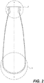
- FIG. 2 is a cross-sectional view of the bottle shown in FIG. 1 , as taken along line 2-2.
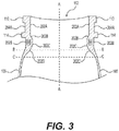
- FIG. 3 is a detailed view of the top end of the cross section of the bottle shown in FIG. 2 .
- FIG. 4 is a detailed view of the lower end of the cross section of the bottle shown in FIG. 2 .
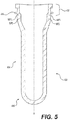
- FIG. 5 is a cross-sectional view of a preform for making the bottle shown in FIG. 1 .
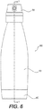
- FIG. 6 is a side view of pressurized dispensing system according to an embodiment of our invention.
- FIG. 7 is a cross-sectional view of a dispensing system shown in FIG. 5 , as taken along line 7-7.
- Our invention generally relates to a pressurized dispensing system that includes a plastic bottle. More specifically, our invention relates to a dispensing system that includes a plastic bottle for containing a product under pressure, with the bottle having a unique configuration that eliminates or reduces undesirable effects such as bursting, failing when dropped, and stress cracking.
- Figure 1 shows a bottle 100 for use in a pressurized dispensing system according to an embodiment of our invention.
- this figure does not include some of the components that would be a part of a complete dispensing system that includes the bottle 100.
- a spray mechanism is not shown at the top of the bottle 100 in Figure 1 , nor does the bottle 100 include a structure at the bottom (e.g., a base cup) that allows the bottle 100 to stand up-right.
- a structure at the bottom e.g., a base cup
- the bottle 100 in this embodiment is made from a plastic material.
- the bottle 100 may be formed using, for example, injection, compression, and/or blow molding techniques, which are well known in the art.
- injection and blow molding processes a plastic preform is first formed using injection molding.
- the plastic preform is subsequently heated and stretch blow molded into the final shape of the bottle 100.
- plastics include branched or linear PET, polycarbonate (PC), polyethylene naphthalate (PEN), nylon, polyethylene furanoate (PEF), polyolefins (PO) such as polyethylene (PE) and polypropylene (PP), and other polyesters, and blends thereof.
- PC polycarbonate
- PEN polyethylene naphthalate
- nylon nylon
- PO polyolefins
- PE polyethylene
- PP polypropylene
- the bottle 100 includes an upper end 102, a base 106, and a body 104 with a sidewall 105 between the upper end 102 and base 106.
- the body 104 of the bottle 100 is round and extends about an axis A.
- the upper end 102 includes a finish 108 having a crimp ring 110 surrounding an opening 112 of the bottle 100.
- a valve (not shown) can be crimped to the crimp ring 110 in order to securely attach the valve to the bottle 100.
- the product contained in the bottle 100 can thereby be dispensed through the valve.
- the finish 108 also includes a transfer ring 114 positioned below the crimp ring 110. During a process for manufacturing the bottle 100, a preform of the bottle 100 may be gripped at the transfer ring 114 to transfer the preform between processing stations.
- the line B-B is shown at a position that generally demarcates the finish 108 and the body 104.
- the line B-B also demarcates the parts of the bottle 100 that are stretched in the blow molding process (i.e., the body 104 and base 106), from the part that is formed in the injection molding process but not reshaped in the blow molding process (i.e., the finish 108). Further details of how the bottle 100 is stretched in the blow molding process will be described below in conjunction with a description of the preform used to make the bottle 100.
- the bottle 100 is manufactured such that no crystallinity is intentionally induced by using heat setting during a stretch blow molding process in which the bottle 100 is formed.
- a process of manufacturing the bottle 100 involving an injection molding and stretch blow molding there is no step, such as heating, that is conducted in order to intentionally increase the crystallinity in a region of the bottle-any crystallinity in the bottle 100 is merely the product of the injection molding and stretch blow molding.
- the crystallinity in the plastic of the bottle 100 is kept low, particularly in the finish region 108 of the bottle 100, which is not subject to stretching in the blow molding process.
- the finish region has less than about 10% crystallinity in the finish region 108, less than about 25% crystallinity in the main body 104, and less than about 15% crystallinity in the base 106.
- Figure 3 is a cross-sectional view of the top end of the bottle 100.
- a first section 202A of the inner surface of the bottle 100 extends downward from the opening 112. This first section 202A is substantially parallel to the axis A until a position that is generally adjacent to the transfer ring 114.
- a second section 202B of the inner surface in the finish 108 region is sloped inward towards the axis A of the bottle 100, with the second section 202B continuing below the transfer ring 114.
- the inner surface has a third section 202C that is sloped outward from the axis A-A.
- the third section 202C continues on to a fourth section 202D of the inner surface that is below the line B-B into the section of the bottle corresponding to the body 104.
- the fourth section 202D then continues to positions on the bottle 100 denoted with the line C-C in Figure 3 .
- the thickness of the bottle 100 decreases to the extent that, at the points corresponding to the line C-C, the bottle 100 has a thickness that is substantially constant through the sidewall 105 of body 104 until the base 106 is reached. It should be noted that a diameter from the axis A-A to the sections 204A and 204B of the outer surface of the bottle above and below the transfer ring 114 is about the same.
- the sections of the finish 102 that include the inner surface sections 202B, 202C, and 202D are thicker compared to a configuration wherein the inner surface section 202A continued in parallel with the axis A-A through the entire neck finish 102. That is, the bottle 100 includes additional material in the section labeled M as compared to a standard bottle configuration.
- An example of a plastic bottle having additional material provided to an outer part of the finish 108 can be seen in U.S. Patent No. 7,303,087 B2 .
- That patent describes a bottle designed to reduce deformation by providing reinforcement to the neck and shoulder regions of a plastic bottle, the reinforcement being achieved by providing an increased thickness of the wall in a direction toward the outside of the bottle.
- Our invention is different in that, instead of providing the additional material on an outer part of the bottle, the additional material is effectively provided to an inner part of the bottle, that is, with a part of the inner surface of the bottle 100 in the finish region 102 and main body portion 104 being sloped inward, as described above.
- the bottle 100 has about 0.25 grams of material per millimeter of length in the distance from just below the transfer ring 114 to the positions where the regular sidewall 105 thickness begins.
- the material making up the bottle 100 can be provided in a distribution so that the sections 202B, 202C, and 202D are sloped, as described above.
- other distributions can be used while still achieving the 0.25 g/mm ratio of weight to length.
- the slope of the inner surface in sections 202C and 202D relative to the outer surface is about 0.35 mm/mm.
- the bottle is provided with outstanding stress cracking in the finish 108 region.
- bottles having such material distributions have synergistic properties when the bottles are provided with the particular base configurations, as discussed below.
- the bottle 100 is configured with a thickness of about 3.75 mm at the beginning of the section 202B, and slopes to a maximum thickness of about 2.85 mm at about 1 mm below the transfer ring 114. The bottle thickness then decreases to a thickness of about 0.80 mm at the points about 7 mm below the crimp ring. And, when the bottle has such dimensions and is made from PET, the bottle is provided with about 1.80 g of material in the length from just below the transfer ring to the points about 7 mm below the crimp ring.
- Figure 4 is a cross-sectional view of the base 106 of the bottle 100.
- the base surface 302 of the bottle 100 has a generally elliptical shape.
- base shapes configured to provide feet on the bottle often bulged outward when test bottles were filled with a product and heated.
- bottles with self-standing bases often failed drop testing, with the shaped bases bursting on impact.
- the self-standing bases added stress points around the base when the bottles were pressurized and stress cracking was often rampant.
- a base cup for example, may be attached to the bottom end (base) 106 of the bottle 100. Details of a base cup and how the base cup can be attached to the bottle 100 can be found in commonly-assigned U.S. Patent Application No. 15/166,337 .
- the base 106 is divided into three equal sections-labeled 1, 2, and 3-between the axis A-A and the end of the base (adjacent to the sidewall 105 of the body 104). That is, the section labeled 1 includes the part of the base 106 between the axis A and a position corresponding to angle ⁇ 1 that is 30° from the axis A, the section labeled 2 includes the part of the base 106 between the section labeled 1 and a position corresponding to angle ⁇ 2 that is 60° from the axis A, and the section labeled 3 includes the part of the base between the section labeled 2 and a position corresponding to angle ⁇ 3 that is 90° from the axis A.
- the base of the bottle 100 is thickest at Section 1, i.e ., the part of the base 106 that is closest to the axis A of the bottle. From this part, the thickness of the base 106 gradually decreases in sections 2 and 3. We have found that such a gradual reduction in thickness of the base 106 is closely related to performance of the bottle in terms of resistant to failure in drop tests and resistance to stress cracking. Moreover, we have found that when the thickness of the base 106 decreases at a rate of about 3.8 mm per mmalong the base 106, a surprisingly high resistance to failure in drop tests and surprisingly high resistance to stress cracking can be achieved.
- the sections 1-3 have certain relative parameters. Specifically, in an embodiment of our invention, the section 1 accounts for about 10% of the total outer surface area of the base 106 and about 20% of the weight of the base 106, the section 2 accounts for about 30% of the total outer surface area of the base 106 and about 45% percent of the weight of the base 106, and the section 3 accounts for about 60% of the total outer surface area and about 35% of the total weight of the base 106. With these parameters, the base 106 has considerable resistance to failure in drop tests and resistance to stress cracking as compared to other configurations.
- Another aspect of the base 106 is relative consistency of the base to withstand impact in different bottles having configurations such as that of bottle 100.
- the maximum force that the base 106 can withstand upon impact may vary for any given bottle design. This is because of many factors that may influence the actual impact resistance of a given bottle, such as the exact processing conditions that were present during the manufacture of the particular bottle. Nevertheless, there is a minimum impact force that a bottle having a particular design must be able to withstand without breaking, for example, to meet the regulations generally discussed above. It is also beneficial if the ability of the base of the bottle to withstand an impact force does not widely vary for a particular bottle design, as this provides assurance as to the reliability of the bottle design.
- One way to determine the impact force that will cause a base to break in a given plastic bottle design is through a high speed puncture test using load and displacement sensors. Such tests can be conducted, for example, using a falling dart test, wherein the load cell inside the dart records the force and energy required to fracture the bases of the test bottles.
- a falling dart test wherein the load cell inside the dart records the force and energy required to fracture the bases of the test bottles.
- the bases in bottles made from PET with configurations according to our invention had a peak force at fracture of between about 450 N and about 700 N.
- the minimum force of about 450 N was greater than the minimum force found with other plastic bottles having different configurations.
- the 250 N range between the minimum and maximum forces was narrower than the ranges for other plastic bottles having different configurations.
- Figure 5 is a cross-sectional view of a preform 400 that can be used to form the bottle 100.
- a preform 400 is an intermediate product in an injection and blow molding process, with the preform 400 being the injection molded product that is subjected to blow molding to form the final product.
- the preform 400 includes a finish section 402 that corresponds to the finish 102 of the bottle 100, a body section 404 that corresponds to the body of the bottle 100, and a base portion 406 that corresponds to the base 106 of the bottle 100.
- the finish portion 402 of the preform 400 is not altered during the blow molding process.
- the finish portion 402 of the preform 400 has the nearly the same configuration as the finish portion 102 of the bottle 100.
- the body portion 404 and base portion 406, however, are stretched into the final shapes of the body portion 104 and base portion 106 of the bottle 100.
- the finish portion 402 of the preform 400 includes thickened material portions MP1 and MP2 that extend downward from the transfer ring 414.
- the thickened material portions MP1 and MP2 correspond to the additional material portion M of the bottle 100, as described above.
- the thickened material portion MP1 is in the finish portion 402 of the preform 400, and therefore has nearly the same configuration as the additional material portion M in the bottle 100.
- the part of the thickened material portion MP1 slopes inward relative to the axis A of the preform 400 in same manner as the inner surface section 202B in the finish 102 of the bottle 100 slopes inward relative to the axis A of the bottle 100.
- the thickened material portion MP2 is positioned within the body portion of the 404 of the preform 400, and, thus, the thickened material portion MP2 is stretched during a blow molding process for making the bottle 100.
- the thickened material portion MP2 therefore has a different configuration than the corresponding part of the additional material portion M of the bottle 100.
- the preform 400 is configured to form a bottle with a rounded base, there are no steps in the base region 402 of the preform 400.
- the preform 400 has a reduced amount of material as compared to a preform that would be used to form a bottle with a non-rounded based (e.g., a bottle with feet for making the bottle stand up-right).
- the reduced amount of material allows for a comparatively reduced cycle time in the production of the bottle.
- crystallinity decreases impact resistance and increases stress cracking.
- the rounded base of the preform 400 is further beneficial in that there is limited interaction with the blow rod that is used to stretch the preform 400 in the blow molding process.
- FIG. 6 and 7 An example of a high-pressure dispensing system 500 using the plastic bottle 100 is shown in Figures 6 and 7 .
- the rounded base 106 of the bottle 100 is attached to a base cup 600.
- the base cup 600 allows the system 500 to stand up-right on a flat surface despite the rounded base 106.
- a spray mechanism 502 which includes a valve 504.
- the pressurized product contained within the bottle 100 is dispensed through the spray mechanism 502.
- a cap may be provided over the spray mechanism 502.
- the system 500 is used to dispense an air freshening composition.
- an air freshening composition examples of formulations for the air freshening composition can be found in commonly assigned U.S. Patent Application No. 15/094,542 .
- pressurized dispensing systems have a wide variety of uses, for example, in the market of aerosol products.
Landscapes
- Engineering & Computer Science (AREA)
- Mechanical Engineering (AREA)
- Chemical & Material Sciences (AREA)
- Dispersion Chemistry (AREA)
- Ceramic Engineering (AREA)
- Containers Having Bodies Formed In One Piece (AREA)
- Containers And Packaging Bodies Having A Special Means To Remove Contents (AREA)
Claims (9)
- Eine Kunststoffflasche (100) zum Aufnehmen eines unter Druck stehenden Produkts, wobei die Kunststoffflasche (100) Folgendes beinhaltet:(a) einen gerundeten Boden (106) an einem unteren Ende der Flasche (100), wobei der gerundete Boden (106) zur Außenseite der Flasche (100) hin gewölbt ist;(b) einen Körper (104), der sich um eine Achse der Flasche (100) von dem Boden (106) in Richtung eines oberen Endes der Flasche (100) erstreckt; und(c) einen Abschluss (108) an dem oberen Ende des Flasche (100), wobei sich der
Abschluss (108) um die Achse der Flasche (100) erstreckt,
wobei die Kunststoffflasche (100) derart konfiguriert ist, dass das Produkt als Aerosol ausgegeben werden kann, und
dadurch gekennzeichnet (106), dass der Boden an einer der Achse der Flasche (100) benachbarten Stelle am dicksten ist, wobei die Dicke mit einer Rate von 3,8 mm pro mm entlang des Bodens (106) von der Achse der Flasche (100) aus abnimmt. - Kunststoffflasche (100) gemäß Anspruch 1, wobei der Abschluss (108) eine Innenoberfläche umfasst, die Folgendes umfasst: (i) einen dem oberen Ende der Flasche (100) benachbarten ersten Abschnitt (202A), wobei sich der erste Abschnitt (202A) im Wesentlichen parallel zu der Achse der Flasche (100) erstreckt, und (ii) einen zweiten Abschnitt (202B), der in Richtung der Achse der Flasche (100) nach innen abgeschrägt ist.
- Kunststoffflasche (100) gemäß Anspruch 2, wobei die Innenoberfläche in dem Abschluss (108) der Flasche (100) einen dem zweiten Abschnitt (202B) benachbarten dritten Abschnitt (202C) umfasst, wobei der dritte Abschnitt (202C) von der Achse der Flasche (100) aus nach außen abgeschrägt ist.
- Kunststoffflasche (100) gemäß Anspruch 3, wobei eine Schräge von mindestens einem Teilabschnitt des dritten Abschnitts (202C) 0,35 mm/mm beträgt.
- Kunststoffflasche (100) gemäß Anspruch 3, wobei mindestens ein Teilabschnitt des dritten Abschnitts (202C) ein Verhältnis von Gewicht zu Länge entlang der Flasche (100) von 0,25 g/mm aufweist.
- Kunststoffflasche (100) gemäß Anspruch 2, wobei die Flasche (100) ferner einen Ring (114) beinhaltet, der sich von einer Außenoberfläche des Abschlusses (108) erstreckt, und
wobei der zweite Abschnitt (202B) der Innenoberfläche an einer dem Ring (114) benachbarten Stelle beginnt. - Kunststoffflasche (100) gemäß Anspruch 1 oder 2,
wobei, wenn der Boden (106) in drei gleiche Abschnitte zwischen einer der Achse der Flasche (100) entsprechenden Stelle und einer dem Körper (104) der Flasche (100) benachbarten Stelle unterteilt ist, ein der Achse der Flasche benachbarter erster Abschnitt 20 % des Gesamtgewichts des Bodens ausmacht, ein dem ersten Abschnitt benachbarter zweiter Abschnitt 45 % des Gesamtgewichts des Bodens ausmacht und ein dem Körper der Flasche benachbarter dritter Abschnitt 35 % des Gesamtgewichts des Bodens ausmacht. - Kunststoffflasche gemäß Anspruch 7, wobei der erste Abschnitt des Bodens (106) etwa 10 % des gesamten Außenoberflächenbereichs des Bodens entspricht, der zweite Abschnitt des Bodens (106) etwa 30 % des gesamten Außenoberflächenbereichs des Bodens entspricht und der dritte Abschnitt des Bodens (106) etwa 60 % des gesamten Außenoberflächenbereichs des Bodens entspricht.
- Kunststoffflasche (100) gemäß einem der vorangehenden Ansprüche, wobei die
Flasche (100) aus Polyethylenterephthalat (PET) hergestellt ist.
Applications Claiming Priority (2)
| Application Number | Priority Date | Filing Date | Title |
|---|---|---|---|
| US15/367,678 US10486891B2 (en) | 2016-12-02 | 2016-12-02 | Plastic bottle for a pressurized dispensing system |
| PCT/US2017/063827 WO2018102482A1 (en) | 2016-12-02 | 2017-11-30 | Plastic bottle for a pressurized dispensing system |
Publications (2)
| Publication Number | Publication Date |
|---|---|
| EP3548401A1 EP3548401A1 (de) | 2019-10-09 |
| EP3548401B1 true EP3548401B1 (de) | 2021-04-28 |
Family
ID=60703167
Family Applications (1)
| Application Number | Title | Priority Date | Filing Date |
|---|---|---|---|
| EP17817545.1A Active EP3548401B1 (de) | 2016-12-02 | 2017-11-30 | Kunststoffflasche für ein druckbeaufschlagtes ausgabesystem |
Country Status (11)
| Country | Link |
|---|---|
| US (1) | US10486891B2 (de) |
| EP (1) | EP3548401B1 (de) |
| JP (1) | JP7017570B2 (de) |
| KR (1) | KR102499643B1 (de) |
| CN (1) | CN110225867B (de) |
| AR (2) | AR110306A1 (de) |
| AU (1) | AU2017368160B2 (de) |
| BR (1) | BR112019011276B1 (de) |
| ES (1) | ES2870131T3 (de) |
| MX (1) | MX2019006404A (de) |
| WO (1) | WO2018102482A1 (de) |
Families Citing this family (6)
| Publication number | Priority date | Publication date | Assignee | Title |
|---|---|---|---|---|
| US10836561B2 (en) | 2018-10-08 | 2020-11-17 | The Procter & Gamble Company | Aerosol dispenser |
| MX2022015412A (es) * | 2020-06-05 | 2023-01-18 | Niagara Bottling Llc | Preforma de recipiente con porción de acabado con evidencia de manipulación indebida. |
| US11972680B2 (en) * | 2020-06-12 | 2024-04-30 | Gojo Industries, Inc. | Base for table top sanitizer dispensing bottles and dispenser bottles |
| EP4177039A4 (de) * | 2020-07-01 | 2024-02-28 | Kirin Holdings Kabushiki Kaisha | Polyethylenfuranoat, herstellungsverfahren für hochviskoses polyethylenfuranoat, polyesterzusammensetzung, polyesterflasche, herstellungsverfahren für polyesterflasche und getränkeprodukt |
| BE1028731B1 (nl) * | 2020-10-23 | 2022-05-23 | Gojara Bvba | Mechanische bevestigingsmiddelen voor opname van een ventielbehuizing, voorvorm, container en spuitbus omvattend de mechanische bevestigingsmiddelen |
| US20250042595A1 (en) * | 2023-08-04 | 2025-02-06 | Canon Kabushiki Kaisha | Liquid storage bottle |
Family Cites Families (83)
| Publication number | Priority date | Publication date | Assignee | Title |
|---|---|---|---|---|
| US2837245A (en) * | 1955-05-12 | 1958-06-03 | Injection Molding Company | Low pressure flexible wall container |
| DE3886184D1 (de) * | 1987-06-26 | 1994-01-20 | Werding Winfried J | Vorrichtung zur lagerung und kontrollierten abgabe von unter druck stehenden produkten und verfahren zu ihrer herstellung. |
| JPH0622862B2 (ja) * | 1988-10-14 | 1994-03-30 | 東洋製罐株式会社 | 耐熱耐圧容器及びその製造方法 |
| GB8917171D0 (en) * | 1989-07-27 | 1989-09-13 | Hoechst Celanese Plastics Ltd | Aerosol container top of plastics |
| DE9007315U1 (de) | 1990-06-09 | 1991-10-10 | Hirsch, Anton, 7928 Giengen | Ventileinheit zum Einsetzen in eine Druckgasverpackung |
| JPH04173538A (ja) * | 1990-10-24 | 1992-06-22 | Toyo Seikan Kaisha Ltd | 耐圧耐熱性二軸延伸ブロー成形合成樹脂ボトル |
| AU115917S (en) | 1990-12-21 | 1992-12-11 | Florbath Profumi Di Parma S P A | Perfume bottle |
| US5750224A (en) | 1991-07-01 | 1998-05-12 | Plm Ab | Plastic container |
| USD344677S (en) | 1992-01-14 | 1994-03-01 | Bareiss Raymond E | Combined bottle and cap |
| US5427258A (en) | 1992-04-09 | 1995-06-27 | Continental Pet Technologies, Inc. | Freestanding container with improved combination of properties |
| ATE157927T1 (de) | 1992-07-07 | 1997-09-15 | Continental Pet Technologies | Verfahren zum formen von einem behälter mit einer seitenwand von hoher kristallinität und einem boden von niedriger kristallinität |
| UY24071A1 (es) | 1994-10-27 | 1996-03-25 | Coca Cola Co | Recipiente y metodo para hacer un recipiente de naftalato de polietileno y copolimeros del mismo |
| CO4520125A1 (es) | 1995-03-29 | 1997-10-15 | Continental Pet Technologies | Envase presurizado para rellenar resistente al resquebrajamiento del bebedero, preforma y metodo para fabricarlos |
| IL117945A (en) | 1995-04-18 | 2000-01-31 | Coca Cola Co | Preform and bottle using pet/pen blends and copolymers |
| ES2104443T3 (es) | 1995-04-27 | 1997-10-01 | Continental Pet De Gmbh | Geometria del fondo de recipientes de pet reutilizables. |
| US5804016A (en) | 1996-03-07 | 1998-09-08 | Continental Pet Technologies, Inc. | Multilayer container resistant to elevated temperatures and pressures, and method of making the same |
| WO1998006557A1 (en) | 1996-08-12 | 1998-02-19 | Crown Cork & Seal Technologies Corporation | Improved plastic container and preform for making |
| US5954224A (en) | 1996-11-01 | 1999-09-21 | Colgate-Palmolive Company | Injection stretch blow molded tubular containers |
| EP0888861A1 (de) | 1996-12-09 | 1999-01-07 | Schmalbach Lubeca Pet Containers Iberia, S.A. | Verfahren zum verbessern von vorförmlingen und durch dieses verfahren hergestellte, leichte vorförmlinge |
| AU5312098A (en) | 1996-12-30 | 1998-07-31 | Carlsberg A/S | Polymer bottle closed by crown cap or such like |
| US6060140A (en) | 1997-04-25 | 2000-05-09 | Eastman Chemical Company | Lightweight bottles and method for making same |
| DE69942126D1 (de) | 1998-05-07 | 2010-04-22 | Kao Corp | Formkörper |
| USD440499S1 (en) | 1998-10-14 | 2001-04-17 | Saint-Gobain Desjonqueres | Bottle |
| USD444707S1 (en) | 1999-05-13 | 2001-07-10 | Benckiser N.V. | Bottle with liquid design |
| USD434663S (en) | 1999-08-30 | 2000-12-05 | Fwj Plastic Packaging, Inc. | Bottle |
| FR2801568B1 (fr) | 1999-11-26 | 2002-05-10 | Oreal | Ensemble de conditionnement en plastique a recyclage ameliore |
| JP3920518B2 (ja) | 2000-01-21 | 2007-05-30 | 株式会社吉野工業所 | 容器連結用密封部を有する薄肉プラスチック製ボトル型容器および容器連結用密封部材 |
| ITMI20011510A1 (it) | 2001-07-16 | 2003-01-16 | Sinco Ricerche Spa | Bottiglie flessibili in resina poliester |
| CN2570208Y (zh) | 2001-09-03 | 2003-09-03 | 珠海中富聚酯啤酒瓶有限公司 | 聚酯啤酒瓶 |
| JP2003104404A (ja) | 2001-09-28 | 2003-04-09 | Aoki Technical Laboratory Inc | 樹脂製チューブ状容器及びそのプリフォーム |
| FR2830844A1 (fr) | 2001-10-12 | 2003-04-18 | Perrier Vittel Man Et Technolo | Contenant pour un produit coulant, procede de fabrication et utilisations dudit contenant |
| JP4080212B2 (ja) | 2002-01-31 | 2008-04-23 | 株式会社吉野工業所 | 合成樹脂製の薄肉ボトル容器 |
| ATE467568T1 (de) | 2002-03-20 | 2010-05-15 | Etrusca Vetreria | Flasche |
| US6585123B1 (en) | 2002-05-22 | 2003-07-01 | Plastipak Packaging, Inc. | Bottle base |
| USD505332S1 (en) | 2002-12-19 | 2005-05-24 | Wolf Concept S.A.R.L. | Container having an insert in a side wall |
| US7028866B2 (en) * | 2003-01-31 | 2006-04-18 | S.C. Johnson & Son, Inc. | Pressurized plastic bottle for dispensing an aerosol |
| US6896147B2 (en) | 2003-02-14 | 2005-05-24 | Graham Packaging Company, L.P. | Base structure for a container |
| US7451886B2 (en) | 2003-05-23 | 2008-11-18 | Amcor Limited | Container base structure responsive to vacuum related forces |
| US6971530B2 (en) | 2003-12-12 | 2005-12-06 | Plastipak Packaging, Inc. | Plastic container having stepped neck finish |
| US7303087B2 (en) | 2003-12-16 | 2007-12-04 | S. C. Johnson & Son, Inc. | Pressurized plastic bottle with reinforced neck and shoulder for dispensing an aerosol |
| US20050242101A1 (en) | 2004-04-29 | 2005-11-03 | Skalitzky Michael J | Seal-coated plastic container for dispensing a pressurized product |
| TWI304373B (en) | 2004-05-14 | 2008-12-21 | Mitsui Chemicals Inc | Polyester resin bottle |
| AR050681A1 (es) | 2004-07-14 | 2006-11-15 | Nestec Sa | Un envase o contenedor formado por una sola pieza o parte exprimible para productos refrigerados o congelados |
| EP1772251B1 (de) | 2004-07-27 | 2015-11-18 | Toyo Seikan Kaisha, Ltd. | Polyesterbehälter mit hervorragender wärmebeständigkeit und stossfestigkeit und herstellungsverfahren dafür |
| KR101237729B1 (ko) | 2004-09-17 | 2013-02-26 | 도요 세이칸 가부시키가이샤 | 열가소성수지로 이루어지는 편평용기 및 그 성형방법 |
| US7820257B2 (en) | 2005-05-11 | 2010-10-26 | The Coca-Cola Company | Preforms for preparing lightweight stretch blow molded PET copolymer containers and methods for making and using same |
| JP4986105B2 (ja) | 2005-09-21 | 2012-07-25 | 株式会社吉野工業所 | ポリエステル樹脂製の耐熱圧性プラスチックボトル |
| DK1954624T3 (en) | 2005-11-29 | 2016-09-05 | Petainer Lidköping AB | System og fremgangsmåde til distribution og dosering af drikkevarer |
| ITMO20060029A1 (it) | 2006-01-27 | 2007-07-28 | Sacmi | Mezzi di chiusura |
| CA2642679C (en) * | 2006-02-14 | 2014-09-02 | Power Container Corp. | Fluid delivery device |
| USD551080S1 (en) | 2006-03-07 | 2007-09-18 | Plastpak Packaging, Inc. | Container base |
| US8960503B2 (en) | 2006-10-19 | 2015-02-24 | Atef Gabr Soliman | Plastic aerosol container |
| WO2008125126A1 (en) | 2007-04-17 | 2008-10-23 | Atef Gabr Solimsn | Plastic aerosol container with cylindrical middle portion and actuation cap |
| US8020717B2 (en) | 2007-04-19 | 2011-09-20 | Graham Packaging Company, Lp | Preform base and method of making a delamination and crack resistant multilayer container base |
| US20090029900A1 (en) | 2007-07-27 | 2009-01-29 | The Procter & Gamble Company | Personal care article for sequentially dispensing compositions with distinct fragrance characters |
| FR2921642B1 (fr) | 2007-09-28 | 2011-07-15 | Power Container Corp | Dispositif de distribution de produit fluide, procede de realisation d'un tel dispositif et appareil pour la mise en oeuvre d'un tel procede |
| FR2926035B1 (fr) | 2008-01-09 | 2017-02-03 | Sidel Participations | Fond de moule pour moule de fabrication de recipients thermoplastiques, et dispositif de moulage equipe d'au moins un moule pourvu d'un tel fond |
| JP5286169B2 (ja) | 2009-06-19 | 2013-09-11 | 株式会社青木固研究所 | 延伸ブローボトルのプリフォーム |
| JP5614609B2 (ja) | 2009-08-31 | 2014-10-29 | 株式会社吉野工業所 | 合成樹脂製壜体及びその製造方法 |
| US8507063B2 (en) | 2009-09-22 | 2013-08-13 | Graham Packaging Lc, L.P. | Pet containers with enhanced thermal properties |
| US8662332B2 (en) | 2009-10-06 | 2014-03-04 | Graham Packaging Company, L.P. | Pasteurizable and hot-fillable plastic container |
| JP5491527B2 (ja) | 2009-12-25 | 2014-05-14 | 日精エー・エス・ビー機械株式会社 | 大型容器の製造方法 |
| WO2011110890A1 (en) | 2010-03-11 | 2011-09-15 | Sa Des Eaux Minerales D'evian Saeme | Method for producing plastic containers by stretch blow molding, preform, container and use of such a container |
| USD665263S1 (en) | 2010-05-10 | 2012-08-14 | Pramit Sanghavi | Bottle |
| BE1019342A5 (nl) | 2010-05-20 | 2012-06-05 | Dispack Projects Nv | Vat uit kunststof, werkwijze voor het vervaardigen daarvan, en ring voor een vat. |
| DE102010022533A1 (de) | 2010-06-02 | 2011-12-08 | Röders Gmbh | Behälterstreckblasvorrichtung sowie Behälterstreckblasverfahren |
| CH703369A1 (de) | 2010-06-24 | 2011-12-30 | Alpla Werke | Preform zur Herstellung von Kunststoffbehältern in einem Streckblasprozess und Verfahren zur Herstellung des Preforms. |
| USD633803S1 (en) | 2010-07-07 | 2011-03-08 | Tricorbraun Inc. | Container bottom |
| US8550272B2 (en) | 2010-07-14 | 2013-10-08 | Graham Packaging Company, Lp | Extrusion blow molded pet container having superior column strength |
| WO2012061885A1 (en) | 2010-11-09 | 2012-05-18 | Southern Star Corporation | Pressurised pet container |
| USD650677S1 (en) | 2010-11-12 | 2011-12-20 | Graham Packaging Company, L.P. | Container base |
| CA3037311C (en) | 2010-11-12 | 2021-09-07 | Niagara Bottling, Llc | Preform extended finish for processing light weight bottles |
| US8935904B2 (en) | 2011-02-22 | 2015-01-20 | Graham Packaging Company, L.P. | Method of stabilizing a plastic aerosol container |
| AU2012290249B2 (en) | 2011-08-01 | 2015-10-01 | Graham Packaging Company Lp | Plastic aerosol container and method of manufacture |
| USD732391S1 (en) | 2012-02-10 | 2015-06-23 | Silgan Plastics Llc | Container with ribbed neck |
| US20130270212A1 (en) | 2012-04-16 | 2013-10-17 | The Procter & Gamble Company | Plastic Bottles For Perfume Compositions Having Improved Crazing Resistance |
| USD715150S1 (en) | 2012-08-22 | 2014-10-14 | Access Business Group International Llc | Container |
| USD696954S1 (en) | 2012-11-30 | 2014-01-07 | Laminados Facarlyte, S.A. De C.V. | Container neck |
| BR112015015139A2 (pt) | 2012-12-24 | 2017-12-12 | Petapak Ip Ltd | conjunto de gola e copo de montagem para recipiente de aerossol de plásticos |
| US9758294B2 (en) | 2013-01-25 | 2017-09-12 | The Procter & Gamble Company | Components for aerosol dispenser and aerosol dispenser made therewith |
| ITRM20130493A1 (it) | 2013-09-05 | 2015-03-06 | Sipa Progettazione Automaz | Preforma per contenitore in materiale plastico |
| GB2524843B (en) | 2014-04-04 | 2018-12-19 | Pet Eng & Services S R L | Pressurised container with pressure relief valve |
| KR101650176B1 (ko) | 2015-04-30 | 2016-08-22 | 유재열 | 유체분사장치 |
-
2016
- 2016-12-02 US US15/367,678 patent/US10486891B2/en active Active
-
2017
- 2017-11-30 ES ES17817545T patent/ES2870131T3/es active Active
- 2017-11-30 EP EP17817545.1A patent/EP3548401B1/de active Active
- 2017-11-30 KR KR1020197016535A patent/KR102499643B1/ko active Active
- 2017-11-30 WO PCT/US2017/063827 patent/WO2018102482A1/en not_active Ceased
- 2017-11-30 CN CN201780083782.1A patent/CN110225867B/zh active Active
- 2017-11-30 JP JP2019528802A patent/JP7017570B2/ja active Active
- 2017-11-30 BR BR112019011276-6A patent/BR112019011276B1/pt active IP Right Grant
- 2017-11-30 AU AU2017368160A patent/AU2017368160B2/en active Active
- 2017-11-30 MX MX2019006404A patent/MX2019006404A/es unknown
- 2017-12-01 AR ARP170103379A patent/AR110306A1/es active IP Right Grant
-
2021
- 2021-04-12 AR ARP210100972A patent/AR121831A2/es active IP Right Grant
Non-Patent Citations (1)
| Title |
|---|
| None * |
Also Published As
| Publication number | Publication date |
|---|---|
| KR102499643B1 (ko) | 2023-02-14 |
| JP2019536704A (ja) | 2019-12-19 |
| BR112019011276B1 (pt) | 2023-10-17 |
| EP3548401A1 (de) | 2019-10-09 |
| KR20190091277A (ko) | 2019-08-05 |
| AR110306A1 (es) | 2019-03-13 |
| AU2017368160A1 (en) | 2019-06-06 |
| AR121831A2 (es) | 2022-07-13 |
| US20180155113A1 (en) | 2018-06-07 |
| CN110225867A (zh) | 2019-09-10 |
| BR112019011276A2 (pt) | 2019-10-15 |
| WO2018102482A1 (en) | 2018-06-07 |
| AU2017368160B2 (en) | 2020-04-16 |
| MX2019006404A (es) | 2019-08-12 |
| US10486891B2 (en) | 2019-11-26 |
| JP7017570B2 (ja) | 2022-02-08 |
| ES2870131T3 (es) | 2021-10-26 |
| CN110225867B (zh) | 2021-02-12 |
Similar Documents
| Publication | Publication Date | Title |
|---|---|---|
| AU2017368160B2 (en) | Plastic bottle for a pressurized dispensing system | |
| US20160236854A1 (en) | Plastic aerosol container | |
| US10301102B2 (en) | Plastic aerosol container and method of manufacture | |
| US10322837B2 (en) | Hot fill container having superior crush resistance | |
| US20080179271A1 (en) | Nitrogen dosed base | |
| AU2017368159B2 (en) | Pressurized dispensing system including a plastic bottle | |
| US10053276B2 (en) | Container provided with a curved invertible diaphragm | |
| CN109789600B (zh) | 由塑料制成的气溶胶容器 | |
| US9073660B2 (en) | Plastics material container with straight aperture areas | |
| SU1709898A3 (ru) | Способ изготовлени емкости типа бутылки из полимерного материала | |
| EP3257768B1 (de) | Behälter mit einer konvexen umkehrbaren membran | |
| WO2014008014A1 (en) | Pressure relief device for pressurized container | |
| EP3621887B1 (de) | Heissfüllbehälter mit wellkerbung | |
| US20110193271A1 (en) | Method and apparatus for stretch blow molding a container | |
| KR102663373B1 (ko) | 가압 보틀 | |
| JPH08207919A (ja) | 耐圧自立型ボトル | |
| EP3458246B1 (de) | Verfahren zur herstellung einer flasche aus einem polymermaterial und flasche | |
| US20200130248A1 (en) | Hot fill container having superior crush resistance | |
| CA2951257A1 (en) | Bottle having one or more internal projections |
Legal Events
| Date | Code | Title | Description |
|---|---|---|---|
| STAA | Information on the status of an ep patent application or granted ep patent |
Free format text: STATUS: UNKNOWN |
|
| STAA | Information on the status of an ep patent application or granted ep patent |
Free format text: STATUS: THE INTERNATIONAL PUBLICATION HAS BEEN MADE |
|
| PUAI | Public reference made under article 153(3) epc to a published international application that has entered the european phase |
Free format text: ORIGINAL CODE: 0009012 |
|
| STAA | Information on the status of an ep patent application or granted ep patent |
Free format text: STATUS: REQUEST FOR EXAMINATION WAS MADE |
|
| 17P | Request for examination filed |
Effective date: 20190515 |
|
| AK | Designated contracting states |
Kind code of ref document: A1 Designated state(s): AL AT BE BG CH CY CZ DE DK EE ES FI FR GB GR HR HU IE IS IT LI LT LU LV MC MK MT NL NO PL PT RO RS SE SI SK SM TR |
|
| AX | Request for extension of the european patent |
Extension state: BA ME |
|
| DAV | Request for validation of the european patent (deleted) | ||
| DAX | Request for extension of the european patent (deleted) | ||
| RIN1 | Information on inventor provided before grant (corrected) |
Inventor name: HARRIS, KIMBERLY J. Inventor name: PRATER, RODNEY L. Inventor name: MCGRATH, DANIEL S. Inventor name: STENMARK, NILES Inventor name: WOLAK, CHRISTOPHER P. |
|
| GRAP | Despatch of communication of intention to grant a patent |
Free format text: ORIGINAL CODE: EPIDOSNIGR1 |
|
| STAA | Information on the status of an ep patent application or granted ep patent |
Free format text: STATUS: GRANT OF PATENT IS INTENDED |
|
| INTG | Intention to grant announced |
Effective date: 20200706 |
|
| RIN1 | Information on inventor provided before grant (corrected) |
Inventor name: WOLAK, CHRISTOPHER P. Inventor name: MCGRATH, DANIEL S. Inventor name: PRATER, RODNEY L. Inventor name: HARRIS, KIMBERLY J. Inventor name: STENMARK, NILES |
|
| GRAJ | Information related to disapproval of communication of intention to grant by the applicant or resumption of examination proceedings by the epo deleted |
Free format text: ORIGINAL CODE: EPIDOSDIGR1 |
|
| STAA | Information on the status of an ep patent application or granted ep patent |
Free format text: STATUS: REQUEST FOR EXAMINATION WAS MADE |
|
| GRAP | Despatch of communication of intention to grant a patent |
Free format text: ORIGINAL CODE: EPIDOSNIGR1 |
|
| STAA | Information on the status of an ep patent application or granted ep patent |
Free format text: STATUS: GRANT OF PATENT IS INTENDED |
|
| INTC | Intention to grant announced (deleted) | ||
| INTG | Intention to grant announced |
Effective date: 20201127 |
|
| GRAS | Grant fee paid |
Free format text: ORIGINAL CODE: EPIDOSNIGR3 |
|
| GRAA | (expected) grant |
Free format text: ORIGINAL CODE: 0009210 |
|
| STAA | Information on the status of an ep patent application or granted ep patent |
Free format text: STATUS: THE PATENT HAS BEEN GRANTED |
|
| AK | Designated contracting states |
Kind code of ref document: B1 Designated state(s): AL AT BE BG CH CY CZ DE DK EE ES FI FR GB GR HR HU IE IS IT LI LT LU LV MC MK MT NL NO PL PT RO RS SE SI SK SM TR |
|
| REG | Reference to a national code |
Ref country code: GB Ref legal event code: FG4D |
|
| REG | Reference to a national code |
Ref country code: CH Ref legal event code: EP |
|
| REG | Reference to a national code |
Ref country code: AT Ref legal event code: REF Ref document number: 1386843 Country of ref document: AT Kind code of ref document: T Effective date: 20210515 |
|
| REG | Reference to a national code |
Ref country code: DE Ref legal event code: R096 Ref document number: 602017037745 Country of ref document: DE |
|
| REG | Reference to a national code |
Ref country code: IE Ref legal event code: FG4D |
|
| REG | Reference to a national code |
Ref country code: LT Ref legal event code: MG9D |
|
| REG | Reference to a national code |
Ref country code: AT Ref legal event code: MK05 Ref document number: 1386843 Country of ref document: AT Kind code of ref document: T Effective date: 20210428 |
|
| REG | Reference to a national code |
Ref country code: ES Ref legal event code: FG2A Ref document number: 2870131 Country of ref document: ES Kind code of ref document: T3 Effective date: 20211026 |
|
| PG25 | Lapsed in a contracting state [announced via postgrant information from national office to epo] |
Ref country code: FI Free format text: LAPSE BECAUSE OF FAILURE TO SUBMIT A TRANSLATION OF THE DESCRIPTION OR TO PAY THE FEE WITHIN THE PRESCRIBED TIME-LIMIT Effective date: 20210428 Ref country code: LT Free format text: LAPSE BECAUSE OF FAILURE TO SUBMIT A TRANSLATION OF THE DESCRIPTION OR TO PAY THE FEE WITHIN THE PRESCRIBED TIME-LIMIT Effective date: 20210428 Ref country code: HR Free format text: LAPSE BECAUSE OF FAILURE TO SUBMIT A TRANSLATION OF THE DESCRIPTION OR TO PAY THE FEE WITHIN THE PRESCRIBED TIME-LIMIT Effective date: 20210428 Ref country code: AT Free format text: LAPSE BECAUSE OF FAILURE TO SUBMIT A TRANSLATION OF THE DESCRIPTION OR TO PAY THE FEE WITHIN THE PRESCRIBED TIME-LIMIT Effective date: 20210428 Ref country code: BG Free format text: LAPSE BECAUSE OF FAILURE TO SUBMIT A TRANSLATION OF THE DESCRIPTION OR TO PAY THE FEE WITHIN THE PRESCRIBED TIME-LIMIT Effective date: 20210728 Ref country code: NL Free format text: LAPSE BECAUSE OF FAILURE TO SUBMIT A TRANSLATION OF THE DESCRIPTION OR TO PAY THE FEE WITHIN THE PRESCRIBED TIME-LIMIT Effective date: 20210428 |
|
| PG25 | Lapsed in a contracting state [announced via postgrant information from national office to epo] |
Ref country code: IS Free format text: LAPSE BECAUSE OF FAILURE TO SUBMIT A TRANSLATION OF THE DESCRIPTION OR TO PAY THE FEE WITHIN THE PRESCRIBED TIME-LIMIT Effective date: 20210828 Ref country code: GR Free format text: LAPSE BECAUSE OF FAILURE TO SUBMIT A TRANSLATION OF THE DESCRIPTION OR TO PAY THE FEE WITHIN THE PRESCRIBED TIME-LIMIT Effective date: 20210729 Ref country code: RS Free format text: LAPSE BECAUSE OF FAILURE TO SUBMIT A TRANSLATION OF THE DESCRIPTION OR TO PAY THE FEE WITHIN THE PRESCRIBED TIME-LIMIT Effective date: 20210428 Ref country code: SE Free format text: LAPSE BECAUSE OF FAILURE TO SUBMIT A TRANSLATION OF THE DESCRIPTION OR TO PAY THE FEE WITHIN THE PRESCRIBED TIME-LIMIT Effective date: 20210428 Ref country code: PT Free format text: LAPSE BECAUSE OF FAILURE TO SUBMIT A TRANSLATION OF THE DESCRIPTION OR TO PAY THE FEE WITHIN THE PRESCRIBED TIME-LIMIT Effective date: 20210830 Ref country code: NO Free format text: LAPSE BECAUSE OF FAILURE TO SUBMIT A TRANSLATION OF THE DESCRIPTION OR TO PAY THE FEE WITHIN THE PRESCRIBED TIME-LIMIT Effective date: 20210728 Ref country code: PL Free format text: LAPSE BECAUSE OF FAILURE TO SUBMIT A TRANSLATION OF THE DESCRIPTION OR TO PAY THE FEE WITHIN THE PRESCRIBED TIME-LIMIT Effective date: 20210428 Ref country code: LV Free format text: LAPSE BECAUSE OF FAILURE TO SUBMIT A TRANSLATION OF THE DESCRIPTION OR TO PAY THE FEE WITHIN THE PRESCRIBED TIME-LIMIT Effective date: 20210428 |
|
| REG | Reference to a national code |
Ref country code: NL Ref legal event code: MP Effective date: 20210428 |
|
| PG25 | Lapsed in a contracting state [announced via postgrant information from national office to epo] |
Ref country code: RO Free format text: LAPSE BECAUSE OF FAILURE TO SUBMIT A TRANSLATION OF THE DESCRIPTION OR TO PAY THE FEE WITHIN THE PRESCRIBED TIME-LIMIT Effective date: 20210428 Ref country code: DK Free format text: LAPSE BECAUSE OF FAILURE TO SUBMIT A TRANSLATION OF THE DESCRIPTION OR TO PAY THE FEE WITHIN THE PRESCRIBED TIME-LIMIT Effective date: 20210428 Ref country code: EE Free format text: LAPSE BECAUSE OF FAILURE TO SUBMIT A TRANSLATION OF THE DESCRIPTION OR TO PAY THE FEE WITHIN THE PRESCRIBED TIME-LIMIT Effective date: 20210428 Ref country code: CZ Free format text: LAPSE BECAUSE OF FAILURE TO SUBMIT A TRANSLATION OF THE DESCRIPTION OR TO PAY THE FEE WITHIN THE PRESCRIBED TIME-LIMIT Effective date: 20210428 Ref country code: SK Free format text: LAPSE BECAUSE OF FAILURE TO SUBMIT A TRANSLATION OF THE DESCRIPTION OR TO PAY THE FEE WITHIN THE PRESCRIBED TIME-LIMIT Effective date: 20210428 Ref country code: SM Free format text: LAPSE BECAUSE OF FAILURE TO SUBMIT A TRANSLATION OF THE DESCRIPTION OR TO PAY THE FEE WITHIN THE PRESCRIBED TIME-LIMIT Effective date: 20210428 |
|
| REG | Reference to a national code |
Ref country code: DE Ref legal event code: R097 Ref document number: 602017037745 Country of ref document: DE |
|
| PLBE | No opposition filed within time limit |
Free format text: ORIGINAL CODE: 0009261 |
|
| STAA | Information on the status of an ep patent application or granted ep patent |
Free format text: STATUS: NO OPPOSITION FILED WITHIN TIME LIMIT |
|
| 26N | No opposition filed |
Effective date: 20220131 |
|
| PG25 | Lapsed in a contracting state [announced via postgrant information from national office to epo] |
Ref country code: IS Free format text: LAPSE BECAUSE OF FAILURE TO SUBMIT A TRANSLATION OF THE DESCRIPTION OR TO PAY THE FEE WITHIN THE PRESCRIBED TIME-LIMIT Effective date: 20210828 Ref country code: AL Free format text: LAPSE BECAUSE OF FAILURE TO SUBMIT A TRANSLATION OF THE DESCRIPTION OR TO PAY THE FEE WITHIN THE PRESCRIBED TIME-LIMIT Effective date: 20210428 |
|
| PG25 | Lapsed in a contracting state [announced via postgrant information from national office to epo] |
Ref country code: MC Free format text: LAPSE BECAUSE OF FAILURE TO SUBMIT A TRANSLATION OF THE DESCRIPTION OR TO PAY THE FEE WITHIN THE PRESCRIBED TIME-LIMIT Effective date: 20210428 |
|
| REG | Reference to a national code |
Ref country code: CH Ref legal event code: PL |
|
| PG25 | Lapsed in a contracting state [announced via postgrant information from national office to epo] |
Ref country code: LU Free format text: LAPSE BECAUSE OF NON-PAYMENT OF DUE FEES Effective date: 20211130 Ref country code: BE Free format text: LAPSE BECAUSE OF NON-PAYMENT OF DUE FEES Effective date: 20211130 |
|
| REG | Reference to a national code |
Ref country code: BE Ref legal event code: MM Effective date: 20211130 |
|
| PG25 | Lapsed in a contracting state [announced via postgrant information from national office to epo] |
Ref country code: LI Free format text: LAPSE BECAUSE OF NON-PAYMENT OF DUE FEES Effective date: 20211130 Ref country code: CH Free format text: LAPSE BECAUSE OF NON-PAYMENT OF DUE FEES Effective date: 20211130 |
|
| PG25 | Lapsed in a contracting state [announced via postgrant information from national office to epo] |
Ref country code: IE Free format text: LAPSE BECAUSE OF NON-PAYMENT OF DUE FEES Effective date: 20211130 |
|
| PG25 | Lapsed in a contracting state [announced via postgrant information from national office to epo] |
Ref country code: CY Free format text: LAPSE BECAUSE OF FAILURE TO SUBMIT A TRANSLATION OF THE DESCRIPTION OR TO PAY THE FEE WITHIN THE PRESCRIBED TIME-LIMIT Effective date: 20210428 |
|
| P01 | Opt-out of the competence of the unified patent court (upc) registered |
Effective date: 20230528 |
|
| PG25 | Lapsed in a contracting state [announced via postgrant information from national office to epo] |
Ref country code: HU Free format text: LAPSE BECAUSE OF FAILURE TO SUBMIT A TRANSLATION OF THE DESCRIPTION OR TO PAY THE FEE WITHIN THE PRESCRIBED TIME-LIMIT; INVALID AB INITIO Effective date: 20171130 |
|
| PG25 | Lapsed in a contracting state [announced via postgrant information from national office to epo] |
Ref country code: MK Free format text: LAPSE BECAUSE OF FAILURE TO SUBMIT A TRANSLATION OF THE DESCRIPTION OR TO PAY THE FEE WITHIN THE PRESCRIBED TIME-LIMIT Effective date: 20210428 |
|
| PG25 | Lapsed in a contracting state [announced via postgrant information from national office to epo] |
Ref country code: MT Free format text: LAPSE BECAUSE OF FAILURE TO SUBMIT A TRANSLATION OF THE DESCRIPTION OR TO PAY THE FEE WITHIN THE PRESCRIBED TIME-LIMIT Effective date: 20210428 |
|
| PG25 | Lapsed in a contracting state [announced via postgrant information from national office to epo] |
Ref country code: TR Free format text: LAPSE BECAUSE OF FAILURE TO SUBMIT A TRANSLATION OF THE DESCRIPTION OR TO PAY THE FEE WITHIN THE PRESCRIBED TIME-LIMIT Effective date: 20210428 |
|
| PGFP | Annual fee paid to national office [announced via postgrant information from national office to epo] |
Ref country code: DE Payment date: 20251022 Year of fee payment: 9 |
|
| PGFP | Annual fee paid to national office [announced via postgrant information from national office to epo] |
Ref country code: GB Payment date: 20251023 Year of fee payment: 9 |
|
| PGFP | Annual fee paid to national office [announced via postgrant information from national office to epo] |
Ref country code: IT Payment date: 20251022 Year of fee payment: 9 |
|
| PGFP | Annual fee paid to national office [announced via postgrant information from national office to epo] |
Ref country code: FR Payment date: 20251023 Year of fee payment: 9 |
|
| PGFP | Annual fee paid to national office [announced via postgrant information from national office to epo] |
Ref country code: ES Payment date: 20251201 Year of fee payment: 9 |