EP3548396B1 - System mit einem deckel und mindestens einem rückhalteteil, kombination aus einem starren kasten und diesem system, verfahren dazu - Google Patents
System mit einem deckel und mindestens einem rückhalteteil, kombination aus einem starren kasten und diesem system, verfahren dazu Download PDFInfo
- Publication number
- EP3548396B1 EP3548396B1 EP17825600.4A EP17825600A EP3548396B1 EP 3548396 B1 EP3548396 B1 EP 3548396B1 EP 17825600 A EP17825600 A EP 17825600A EP 3548396 B1 EP3548396 B1 EP 3548396B1
- Authority
- EP
- European Patent Office
- Prior art keywords
- cover
- valve
- chamber
- control device
- inner chamber
- Prior art date
- Legal status (The legal status is an assumption and is not a legal conclusion. Google has not performed a legal analysis and makes no representation as to the accuracy of the status listed.)
- Active
Links
Images





Classifications
-
- B—PERFORMING OPERATIONS; TRANSPORTING
- B65—CONVEYING; PACKING; STORING; HANDLING THIN OR FILAMENTARY MATERIAL
- B65D—CONTAINERS FOR STORAGE OR TRANSPORT OF ARTICLES OR MATERIALS, e.g. BAGS, BARRELS, BOTTLES, BOXES, CANS, CARTONS, CRATES, DRUMS, JARS, TANKS, HOPPERS, FORWARDING CONTAINERS; ACCESSORIES, CLOSURES, OR FITTINGS THEREFOR; PACKAGING ELEMENTS; PACKAGES
- B65D77/00—Packages formed by enclosing articles or materials in preformed containers, e.g. boxes, cartons, sacks or bags
- B65D77/04—Articles or materials enclosed in two or more containers disposed one within another
- B65D77/06—Liquids or semi-liquids or other materials or articles enclosed in flexible containers disposed within rigid containers
-
- B—PERFORMING OPERATIONS; TRANSPORTING
- B67—OPENING, CLOSING OR CLEANING BOTTLES, JARS OR SIMILAR CONTAINERS; LIQUID HANDLING
- B67D—DISPENSING, DELIVERING OR TRANSFERRING LIQUIDS, NOT OTHERWISE PROVIDED FOR
- B67D1/00—Apparatus or devices for dispensing beverages on draught
- B67D1/0001—Apparatus or devices for dispensing beverages on draught by squeezing collapsible or flexible storage containers
-
- B—PERFORMING OPERATIONS; TRANSPORTING
- B67—OPENING, CLOSING OR CLEANING BOTTLES, JARS OR SIMILAR CONTAINERS; LIQUID HANDLING
- B67D—DISPENSING, DELIVERING OR TRANSFERRING LIQUIDS, NOT OTHERWISE PROVIDED FOR
- B67D1/00—Apparatus or devices for dispensing beverages on draught
- B67D1/04—Apparatus utilising compressed air or other gas acting directly or indirectly on beverages in storage containers
- B67D1/0462—Squeezing collapsible or flexible beverage containers, e.g. bag-in-box containers
Definitions
- the present invention relates to a rigid box with a wall defining an inner chamber into which extends a flexible bag for a liquid or viscous food to be consumed in a suitable serving temperature range, whereby the flexible bag is associated with a part comprising a valve.
- the box is provided with at least one, preferably two or more than two passages suitable for the flow of an aqueous medium within the inner chamber outside the flexible bag so as to control the temperature of the food to be consumed.
- the box of the invention is a rigid box containing a bag designed to contain a liquid or viscous food, this food being intended to be dispensed into a consumer's container, said food being advantageously be kept free of oxygen and preferably of light, to avoid unwanted oxidation of the food and thus ensure better preservation of the food.
- the present invention is an improvement of WO 2015/184513 .
- An inner bag housed in an outer bag, the inner bag being filled with liquid while the outer bag is designed to receive air to pressurise the inner bag and allow the liquid to flow, is known from US patent US6247619 .
- US patent application US2012 / 0024896 also describes an inner bag housed in an outer bag, the inner bag containing the liquid for consumption while the outer bag contains the ice or refrigerant material.
- US patent application US2009 / 0078721 describes a container designed to receive a bag filled with wine.
- the container may be placed in a refrigerator.
- the bag is associated with a means of dispensing, such as a valve with a pushbutton or tap.
- US patent US7896199 describes an inner bag housed in an outer bag, for example for containing ice.
- the "cubybox” which is a cardboard box containing a bag filled with wine associated with a valve, is also known.
- the present invention relates to a box to solve these problems among other things.
- the box comprises a bag associated to a valve system, the opening thereof being not dependent from a movement of the whole cover.
- the cover in the box of the invention is adapted to maintain the position of the body of the valve device when a movable control device of the valve is moving.
- the valve device can be independently mounted on the bag, so as to close the bag, before associating the valve device to the cover.
- an apparatus which can be associated with such a box or boxes, allowing inter alia dispensing from the top without introducing air into the bag while ensuring an appropriate temperature for the food dispensed, with as little noise as possible.
- the same liquid circulates in the box (outside the bag) to ensure an appropriate temperature of the liquid food present in the bag, and to ensure (slight) pressurization of the contents of the bag to allow dispensing of the liquid food without the use of a food dispensing pump.
- Such an apparatus allows control of the dispensing (without sudden variation in flow rate; dispensing controlled independently from the amount of liquid still present in the bag) according to the pressure of the liquid present in the box outside the bag.
- the invention is defined by the system of claim 1 comprising a cover and at least a retention part, by the combination of claim 5 and by the method of claim 11. It is disclosed a rigid box having wall or walls defining an inner chamber into which extends a flexible bag or inner bag for containing a liquid or viscous food to be consumed (e.g. wine, a sauce, an alcoholic beverage, etc.) in a suitable serving temperature range (for example from 3 to 20 °C for wines, spirits, soft drinks, for example from 6 to 12 °C for white or rosé wines, 15 to 20 ° C for red wine, 30 to 80 °C for a sauce, etc.).
- a suitable serving temperature range for example from 3 to 20 °C for wines, spirits, soft drinks, for example from 6 to 12 °C for white or rosé wines, 15 to 20 ° C for red wine, 30 to 80 °C for a sauce, etc.
- the flexible bag (4) is associated with a part (5) comprising a valve device or a part (5) comprising a membrane or associable with a protection means (6) designed to cooperate with a part (7) comprising a valve device.
- the box is advantageously provided or associated with a means for protecting the wall or walls (2) against the liquid aqueous medium for heating or cooling the food to be consumed, i.e. flowing within the inner chamber (3).
- the wall or walls (2) have advantageously a side (2C) facing the inner chamber (3) resistant to an aqueous medium at a temperature at least close to the appropriate serving temperature range.
- the flow of medium in the container outside the bag is preferably operated between an bottom opening and an upper opening.
- At least a portion of a side wall (2) of the boxes located between the lower part (1I) and the upper part (1S) comprises preferably along its side facing the inner chamber (3) at least one means for forming one or more guide channels (12) for said aqueous medium and/or is associated with a means for forming one or more guide channels (12), said guide channel(s) (12) being designed so that even in the presence of the flexible or soft bag (4) in the chamber (3), one or more channels (12) are or remain(s) open for passage of the aqueous medium.
- the bag is preferably made of plastic with an aluminium layer. When the rigid box is opaque, it is possible for some foods to use non-opaque bags.
- the wall or walls of the box have advantageously an inner side or surface facing the inner chamber designed to withstand an aqueous medium (e.g. water, possibly with an additive, such as citric acid, a surfactant or a glycol, but preferably drinking water) at a temperature at least close to the appropriate serving temperature range (the temperature of the aqueous medium depends for example on the ambient temperature.
- an aqueous medium e.g. water, possibly with an additive, such as citric acid, a surfactant or a glycol, but preferably drinking water
- the temperature of the aqueous medium depends for example on the ambient temperature.
- the ambient temperature is greater than the food serving temperature (it is therefore necessary to cool the food or to maintain the food at its serving temperature, avoiding warming due to the ambient temperature)
- the temperature of the aqueous medium will then advantageously be cooler than the optimum food serving temperature, for example between 1 and 10 °C, such as from 2 to 5 °C.
- the temperature of the aqueous medium will advantageously be greater than the appropriate serving temperature of the food, for example between 1 and 20 ° C, in particular from 2 to 10 °C.
- valve device also refers to a tap or any other system designed to control the flow of food out of the bag, said valve device comprising a body 602C with movable control device 601 for the valve 5V.
- the open channel(s) are designed to provide an aqueous medium passage between the wall(s) of the box and the bag, and thus ensure a good flow of the aqueous medium in the box to provide optimum cooling or heating of the food contained in the bag or to maintain a substantially optimal temperature for the food to be consumed.
- the aqueous medium introduced into the box also allows the food present in the bag to be pressurized, so as to allow a quantity of food to come out of the bag and the box to be consumed at a temperature close to the optimum temperature.
- the more the bag empties the greater the amount of aqueous medium present in the box, which will allow a more rapid temperature adjustment of the food in the bag.
- the amount of food in the bag is still large, the amount of aqueous medium in the box is reduced.
- dispensing a quantity of food will have little influence on the temperature of the food present in the bag.
- the bag is suspended in the box. This ensures that all solid particles remain in the bottom of the bag and are not served for consumption. This prevents deposits in a dispensing channel or in a valve device or tap.
- the combination has one or more of the following features:
- the passage (10) of the bottom wall (8) forming the bottom can be designed to provide both the supply of a liquid in the part of the inner chamber (3) outside the bag (4), and removal or extraction of liquid from said portion of the chamber outside the bag.
- the passage may be unique or may be separate, for example to channel the flow of incoming liquid at least partially in the portion of the chamber, for example by means of a pipe extending into the chamber and having one end in the vicinity of the upper end, and/or
- the means can also be a portion of the tube 611 entering within the chamber 3, and/or
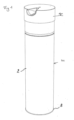
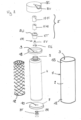
- FIG 1 shows a preferred box (1) according to WO 2015/184513 ( Figure 2 being an exploded view thereof).
- This box (1) is associated with a cap (1C) attached to the body (1).
- the walls (2) define an inner chamber (3) into which extends a flexible bag (4) for containing a liquid or viscous food for consumption in a suitable temperature range.
- Said bag (4) is associated with a valve (5).
- At least a portion of a side wall (2) of the box (1) between the lower part (II) and the upper part (1S) comprises along its side facing the inner chamber (3) at least one means (like a net 12) for forming one or more guide channels for said aqueous medium, said guide channel or channels (12) being designed so that even in the presence of the soft/flexible bag (4) in the chamber (3), one or more channels (12) are or remain open for passage of the aqueous medium.
- the bag (4) is suspended in the box (1), and more precisely in the chamber (3). This allows the particles which may be present in the liquid, for example beverage, wine, etc., to remain in the bag during extraction of the liquid (beverage, wine, etc.) from the bag for dispensing to consumers.
- the box (1) has, near its upper part (1S), at least one passage designed to form a connection between the part of the inner chamber (3) located outside said bag (4) and an inlet and/or outlet pipe (15).
- At least a portion of a side wall (2) of the box (1) between the lower part (1I) and the upper part (1S) comprises along its side facing the inner chamber (3) at least one means (12) to form a series of guide channels for said aqueous medium, said guide channel(s) being designed so that even in the presence of the flexible bag in the chamber, one or more channels are open to the passage of the aqueous medium, said channels advantageously being distributed along said side wall.
- the top wall (18) has only one passage (9) communicating with the inside of the bag (4), said passage (9) being associated with a part (5) comprising a valve (5V) movable between a closed position opposing the passage of liquid out of the bag and an open position against the action of a biasing or return means (5R), while the bottom (8) has only a single central opening (10) communicating with the part of the inner chamber (3) of the box located outside the bag (4), said opening (10) being shut off by a seal or film (8F) which is for example tearable or able to be peeled off or torn or partially or totally pierced or pierceable, for example attached by one or more washers (8R).
- a seal or film (8F) which is for example tearable or able to be peeled off or torn or partially or totally pierced or pierceable, for example attached by one or more washers (8R).
- Said opening (10) is designed to be associated with a liquid inlet pipe and an outlet pipe (or with a pipe having an inlet channel and an outlet channel).
- the washers or rings (8R) are advantageously designed to provide sealing between the cover and the inlet and outlet pipe when the latter is mounted on the bottom (8).
- the biasing or return means (5R) of the valve (5V) may be of the spring type or a resiliently deformable material (for example elastomeric) which once deformed tends to return to its initial or undeformed shape.
- the part (5) is a pipe (5T) with a flange (5U) resting on or attached to the top wall (18).
- the box is associated with a cover (1C) with a spout (BV), said cover (1C) being associated with a mechanism (M10,M11) designed at least to control the opening of the valve (5V).
- the box may be marketed with the cover (C) associated with the box or capable of being mounted on the box (removably or not).
- the mechanism designed at least to control the opening of the valve (5V) comprises at least one means (M10) movable between a raised position in which the valve (5V) is in the closed position (to prevent the passage of liquid through the pipe (5T) and a lowered position in which the valve (5V) is in the open position against the action of the biasing means (5R), said means (M10) being adapted to or associated with a means (M11) designed to cooperate with the pipe (5T) in a relative position of said means with respect to said pipe (5T) to hold said means (M10) in the lowered position and maintain the valve (5V) in the open position. Further details of said box are disclosed in WO 2015/184513 published on December 10, 2015 .
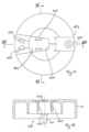
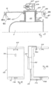
- Figures 3 to 17 are views of an embodiment of a combination of a box and system ( cover and retention part) of the invention or of parts of the combination of the invention.
- the rigid box presenting a container (1) whose wall or walls (2) define an inner chamber (3) in which there extends a soft bag (4) for a liquid or viscous food to be consumed in an appropriate serving temperature range, said bag (4) being associated with a part (5) associated with a valve device with a body (602C) with a movable control device 601 to move the valve 5V between at least an open position and a closed position, said container (1) having a lower part (1I) with a bottom (8) presenting at least one opening (10) which can if necessary be closed by a means (6A - membrane, re-sealable membrane or tearable membrane) and which communicates with the inner chamber (3), an upper part (1S) with a plate element (18) with at least one passage (9) for the part (5) or a portion thereof.
- the wall (2) has a side (2C) facing the inner chamber (3) resistant to an aqueous medium at a temperature at least close to the appropriate serving temperature range.
- the upper part (1S) of the (cylindrical) container is associated with a cover (1C) having an opening or passage (625) for an element capable of acting on the movable control device (601) of the valve device, this cover (1C) being associated with a spout (BV).
- the cover (1C) defines a chamber (600) to accommodate at least partially the body 602C with the movable control device (601) of the valve device, said cover (1C) comprising one or more means (603, 604) to attach said body (602C) of the valve device to the cover (1C) and maintain said body of the valve device in position during the movement of said movable control device (601) inside said chamber (600) of the cover (1C).
- the cover (1C) is associated with at least one means of positioning (603, 604) of the body (602C) with the movable control device (601) in the chamber (600) of the cover (1C), and with at least one retention part (605) for said body (602C) with the movable control device (601) of the valve device, said retention part (605) being movable relative to said cover (1C) between a retention position in which said retention part (605) opposes withdrawal of the part, portion or body (602C) with the movable control device (601) of the valve device from the chamber (600) of the cover (1C), and a non-retention position in which said retention part (605) does not oppose withdrawal of the portion or body with the movable control device (601) of the valve device from the chamber (600) of the cover (1C).
- the cover (1C) has, in its chamber (600), at least two tabs (603) which are spaced apart from each other and flexible, said tabs (603) serving as a means to cooperate with the portion (in this case the substantially cylindrical body) comprising the movable control device (601) of the valve device to ensure positioning of said portion in the chamber (600) of the cover (1C).
- the cover (1C) also has a stop (604) in its chamber (600), said stop serving as a support for a wall (606) of the portion with the movable control device (601) of the valve device to limit or prevent movement of said body of the valve device during relative movement of the movable control device (601) with respect to said body of the valve device. This stabilizes the body during the movements of the movable control device and its lugs (608).
- the body (602C) associated with the movable control device (601) of the valve device has a hollow body (607) with two windows (607F), while the movable control device (601) comprises two lugs (608) extending outside said hollow body (607) through said windows (607F).
- a biasing means (5R) such as a rubber hemispheric element, which could be replaced by a spring element
- said biasing means (5R) exerting a force opposing the movement of said lug or lugs (608) towards its/their second position(s).
- This biasing means (5R) is for example a substantially hemispherical hollow rubber body carrying at its top the valve (5V) designed to close the opening (directed towards the inner chamber of the body 607) of the tube (615) extending the body (602C).
- This biasing means (5R) is located inside the hollow of the body (607), the latter having a support stop or an abutment (607B) for the circular base (5RB) of the biasing means (5R).
- a rod (608R) extends between a recess of the valve (5V) and a support for the lugs (608), passing through the hollow of the biasing means (5R).
- the biasing means (5R) When the lugs are moved towards the stop (604), the biasing means (5R) is elastically deformed, its central part being retracted in the hollow of the body (607) in the direction of the stop or wall (604) of the cover (1C) (or towards the wall (606) of the body (602C)). When the lugs (608) are no longer used to apply a thrust, the biasing means (5R) returns to its initial position, in which the valve 5V closes the opening of the tube 615 forming an extension of the body (602C).
- the body (602C) is connected to the element (618) by a pipe or hollow connecting element (618C) whose internal passage (618CI) forms a communication between the chamber (607) (or its first part directed towards the tube (615)) and the internal passage (619) of the element (618).
- the valve (5V) closing the inner opening of the pipe (615) is moved inside the chamber (607) away from said inner opening, with the result that a passage is formed between the inside of the bag (4) and the tube (615), via the passage (619), the pipe (618CI) and the inner chamber (607).
- valve (5V) and the biasing means (5R) are attached the one to the other by means of an intermediate portion (51).
- the valve, the biasing means and the intermediate portion form one single piece, for example a single rubber piece.
- the biasing means 5R divides the inner chamber of the hollow body (607) into two distinct chambers, namely a first chamber directed towards the outlet tube (615), and a second chamber with the windows (607F).
- the tabs (603) extending in the chamber (600) of the cover (1C) serve as a means of positioning of the lugs (608) of the body with the movable control device (601) of the valve device in the chamber (600) of the cover (1C).
- the lugs are thus located between the tabs (603) and the stop or abutment (604) of the cover (1C).
- the lugs (608) are movable (in the direction of the axis B-B) against a biasing means (5R) between an adjacent position of the lugs (608) (closed position of the valve), and a remote position of the lugs (608) (open position of the valve).
- the axial movement of the lugs (608) is in any way limited by the windows (607F).
- the container (1) has a central axis (A-A), while the movable control device (601) moves in a direction (B-B) perpendicular or substantially perpendicular to said central axis (A-A) of the container (1). This makes it possible to exert a force tending to separate the cover (1C) from the container (1) or to fix the cover (1C) on the container, without acting on the movable control device (601).
- the plate element (18) of the upper part (1S) (the plate closes the upper opening of the container (1)) has a means (610) cooperating with the cover (1C) to limit and preferably prevent rotation of the cover (1C) relative to the container (1) or to the top plate (18).
- the plate (18) has for example a circular lower groove designed to accommodate the upper edge of the container (1) with an interposed layer of glue.
- the plate (18) also has a circular upper groove designed to accommodate a circular edge of the cover (1C).
- This plate (18) has a passage or a recess (610), while the cover (1C) has a tube or hollow protrusion (611) extending in said passage or recess (610) to limit or prevent rotation of the cover relative to the container or to the plate (18).
- the plate (18) has a passage or opening (610) towards the inner chamber (3) of the container (1), while the protrusion (611) is an open pipe carried by the cover (1C) and adapted to extend through the said opening (610), thus enabling passage of air or liquid into the inner chamber (3) via the pipe (611) carried by the cover (1C), a seal (612) advantageously surrounding the pipe (611) to be compressed between a flat support (613) of the pipe (611) and the plate (18) of the upper part (1S) of the container (1).
- the container (1) has a central axis (A-A), in which the retention part (605) is movable in a direction (C-C, for example parallel to the direction B-B) perpendicular to said central axis (A-A), said retention part (605) comprising a spout (BV), an open end tube (614) adapted to accommodate one end of an outlet channel (615) of the valve device.
- the plate (18) has a first side (18A) facing the inner chamber (3) and a second side (18B) opposite the first side and facing the chamber (600) of the cover (1C).
- the soft or flexible bag (4) is associated with a hollow tip (617), while the valve device is associated with an element (618) presenting an inner open channel (619), a transverse section enabling the insertion of the element (618) in the hollow tip (617), and a clamp (620) bearing, possibly with an interposed seal, on the second side (18B) of said plate (18).
- a seal (621) surrounding said element (618) of the valve device bears on the first side (18A) of the plate (18), and is preferably compressed between a far edge (617A), advantageously with a collar, of the hollow tip (617) and said first side (18A) of the plate (18).
- the lower plate 8 has a peripheral circular groove (10G) designed to accommodate the lower edge of the container (1), with an interposed layer of glue.
- the lower plate has a central opening (10) which can be closed by a peelable or tearable film or pierceable and resealable membrane when it is positioned on a support of an apparatus.
- the retention part (605) is held in position on the cover (1C) by a clip system or a system for insertion of a protrusion (622), possibly carried by a strip (624), in a recess or window (623).
- the retention part (605) has two windows (625) giving access to the movable control device (601) of the valve device located in the chamber (600) of the cover (1C), the window(s) (625) being positioned to enable the insertion in the chamber (600) of the cover of an end or ends (630) of a tool (631) to apply a force on the movable control device (601), said windows (625) being advantageously also positioned to enable the insertion of a tool to detach the retention part (605) from the cover (1C).
- the bag (4) comprises a first soft element (4B) and a second soft element (4A) bonded together to form a soft pouch, the first element (4B) being less supple or less soft than the second element (4A), this second element (4A) having an area facing the inside of the pouch at least 50% and preferably 75% to 300% greater than the area of the first element (4B) facing the inside of the pouch, and in that advantageously the tip (617) of the soft bag is attached to said second soft element (4A) near one of its edges bonded to the first soft element (4A).
- the soft bag (4) is surrounded by a soft net (626) serving as a means to ensure that channels exist between the inner face of the container and the soft bag to enable passage of liquid around the bag during the operations to extract liquid food from the bag.
- a soft net (626) serving as a means to ensure that channels exist between the inner face of the container and the soft bag to enable passage of liquid around the bag during the operations to extract liquid food from the bag.
- the hollow tip (617) advantageously has a lower collar (617B) bonded to the film (4A). ( figure 7 )
- the cover (1C) has a positioning hollow or recess (627), said hollow or recess extending along the side or lateral face (1CL) of the cover (1C)( figure 11 ).
- the box is associated with one or more protection means (6, 6A, 6B, 6C) to secure the closing of a passage or passages or windows before the box is used.
- protection means are tearable or detachable flexible films, or tearable or deformable elements for the windows of the retention part of the cover (1C) or membrane elements which can be pierced and sealed back after being pierced.
- Figures 18 and 19 are views of a unit of an apparatus for dispensing a quantity of a liquid or viscous food contained in a bag placed in a box of the combination according to the invention, in an appropriate temperature range, said apparatus comprising at least:
- the mobile tool has at least one claw-shaped element (631) capable of moving through a window (625) of the retention part (605) at least between a position acting on the movable control device (601) of the valve to bring it into the open position and a rest position in which the movable control device (601) of the valve is in a position corresponding to a closed position of the valve.
- the mobile tool (631) has at least one claw-shaped element capable of moving (advantageously by at least one pivoting movement), between a position in which the claw is located outside the chamber of the cover of the box and a position in which the claw has an end located in the chamber of the cover and acts on the movable control device of the valve to bring it into the open position, with an intermediate position in which the claw is in a position in which the claw has an end located in the chamber of the cover, without acting on the movable control device of the valve to bring it into the open position.
- the apparatus comprises a means to ensure correct positioning of the box with respect to the bottom of the apparatus.
- the unit comprises a support plate (PS) for the base of the container (1), said plate (PS) rotating (for example via a controlled motor (PSM)) around a substantially vertical or vertical axis (to be parallel to the central axis A-A of the container (1)), and a protrusion (150) on the rear face of the unit (100), this protrusion being designed to fit into the recess (627) of the cover (1C).
- PSM controlled motor
- the claw-holder (105) is moved, for example by an actuator (105V) in a vertical direction (either the claw-holder (105) is moved downwards, towards the cover (1C), or the plate (PS) is moved upwards), so as to bring the claws (631) close to the windows (625) of the retention part (605), and position them to allow them by a rotational movement to enter the hollow of the cover through the windows (625), to oppose removal of the box and to act on the lugs (608) of the movable control device.
- an actuator (105V) in a vertical direction (either the claw-holder (105) is moved downwards, towards the cover (1C), or the plate (PS) is moved upwards)
- the claws (631) close to the windows (625) of the retention part (605
- the plate (PS) is moved upwards
- the rotational movement of the claws (631) can be carried out in a first step to bring the claws in a first position (631bis) opposing the withdrawal of the box, while not acting on the lugs 608, and in a second step to move the claws from the first position up to a second position (631ter) (opposing the withdrawal of the box and acting on the lugs for opening the valve 5V).
Landscapes
- Engineering & Computer Science (AREA)
- Mechanical Engineering (AREA)
- Packages (AREA)
- Devices For Dispensing Beverages (AREA)
- Closures For Containers (AREA)
Claims (11)
- Ein System, das einen Deckel (1C) und mindestens ein Rückhalteteil (605) aufweist,wobei das System für eine Kombination eines starren Gehäuses und des Deckels (1C) geeignet ist, wobei das starre Gehäuse einen Behälter (1) mit mindestens einer Wand (2) aufweist, die eine innere Kammer (3) definiert, in der sich ein flexibler Beutel (4) für ein flüssiges oder viskoses Lebensmittel, das in einem geeigneten Serviertemperaturbereich zu verzehren ist, unter Verwendung eines in der inneren Kammer (3) fließenden wässrigen Mediums erstreckt, wobei der Beutel (4) mit einem Teil (5) verbunden ist, der mit einer Ventilvorrichtung mit einem Körper (602C) mit einer beweglichen Steuervorrichtung (601) verbunden ist, um ein Ventil (5V) zwischen mindestens einer offenen Position und einer geschlossenen Position zu bewegen, wobei der Behälter (1) einen unteren Teil (11) mit einem Boden (8) aufweist, wobei der untere Teil (11) oder Boden (8) mindestens eine Öffnung (10) aufweist, die mit der inneren Kammer (3) eines Elements zur Bildung einer solchen Öffnung (10) in Verbindung steht, wobei der Behälter (1) einen oberen Teil (1S) mit einem oberen Plattenelement (18) mit mindestens einem Durchlass (9) für mindestens einen Abschnitt des Teils (5) aufweist, bei dem der obere Teil (1S) des Behälters mit dem Deckel (1C) verbunden werden kann, wobei der Behälter eine Mittelachse (A-A) aufweist,der Deckel (1C) eine Kammer (600) definiert, die geeignet ist, zumindest teilweise den Körper (602C) mit der beweglichen Steuervorrichtung (601) der Ventilvorrichtung aufzunehmen, der Deckel (1C) ein oder mehrere Mittel (603, 604) aufweist, um den Körper (602C) der Ventilvorrichtung an dem Deckel (1C) zu befestigen und den Körper (602C) der Ventilvorrichtung während einer Bewegung der beweglichen Steuervorrichtung (601) innerhalb der Kammer (600) des Deckels (1C) in Position zu halten, der Deckel (1C) einen oder mehrere Durchlässe für ein Element aufweist, das direkt oder unter Zwischenschaltung eines Zwischenstücks auf die bewegliche Steuervorrichtung (601) des Ventils (5C) einwirken kann, dadurch gekennzeichnet, dass der Deckel (1C) in seiner Kammer (600) mindestens zwei voneinander beabstandete Laschen (603) aufweist, von denen mindestens eine flexibel ist, wobei die Laschen (603) als Mittel zum Zusammenwirken mit dem Körper (602C) mit der Steuervorrichtung (601) der Ventilvorrichtung dienen, um die Positionierung des Körpers (602C) in der Kammer (600) des Deckels (1C) sicherzustellen, der Deckel (1C) mit dem mindestens einen Rückhalteteil (605) verbunden ist,das Rückhalteteil so konfiguriert ist, dass es in einer Richtung (C-C) im Wesentlichen senkrecht zu der Mittelachse (A-A) beweglich ist, wobei das Rückhalteteil einen Ausguss (BV) aufweist, dessen offenes Ende ein Ende eines Auslasskanals des Ventilkörpers aufnehmen kann, wobei der Deckel (1C) mit dem Ausguss (BV) verbunden ist,das Rückhalteteil (605) relativ zu dem Deckel (1C) zwischen einer Rückhalteposition, in der das Rückhalteteil (605) dem Herausziehen des Körpers (602C) mit der Steuervorrichtung (601) der Ventilvorrichtung aus der Kammer (600) des Deckels (1C) entgegenwirkt, und einer Nicht-Rückhalteposition, in der das Rückhalteteil (605) dem Herausziehen des Körpers (602C) mit der beweglichen Steuervorrichtung (601) der Ventilvorrichtung aus der Kammer (600) des Deckels (1C) nicht entgegenwirkt, bewegbar ist, undwobei das Rückhalteteil (605) mindestens ein Fenster, vorteilhafterweise zwei Fenster (625), aufweist, die den Zugang zu der in der Kammer (600) des Deckels (1C) angeordneten beweglichen Steuervorrichtung (601) der Ventilvorrichtung ermöglichen, wobei das oder die Fenster (625) so angeordnet sind, dass sie das Einführen eines Endes oder von Enden (630) eines Werkzeugs (631) in die Kammer (600) des Deckels (1C) ermöglichen, um eine Kraft auf die bewegliche Steuervorrichtung (601) oder auf ein auf die bewegliche Steuervorrichtung (601) wirkendes Zwischenelement auszuüben.
- System nach Anspruch 1, bei dem der Deckel (1C) in seiner Kammer (600) einen Anschlag (604) aufweist, wobei der Anschlag (604) als Stütze für eine Wand (606) des Körpers (602C) mit der Steuervorrichtung (601) der Ventilvorrichtung dient, um die Bewegung des Körpers (602C) der Ventilvorrichtung während der Relativbewegung der Steuervorrichtung (601) in Bezug auf den Körper (602C) der Ventilvorrichtung zu begrenzen oder zu verhindern.
- System nach Anspruch 1 oder 2, wobei die bewegliche Steuervorrichtung (601) mindestens einen und vorteilhafterweise zwei Ansätze (608) aufweist, die sich außerhalb des Körpers (602C) erstrecken, wobei die Laschen (603), die sich in der Kammer (600) des Deckels (1C) erstrecken, so konfiguriert sind, dass sie als Mittel zur Positionierung des Ansatzes oder der Ansätze (608) des Körpers (602C) mit der Steuervorrichtung (601) der Ventilvorrichtung in der Kammer (600) des Deckels (1C) dienen, wobei der Ansatz oder die Ansätze (608) des Körpers (602C) relativ zum Körper (602C) gegen die Wirkung des Vorspannmittels (5R) zwischen einer ersten Position, die der geschlossenen Position des Ventils (5V) entspricht, und einer zweiten Position, die der offenen Position des Ventils (5V) entspricht, beweglich ist/sind, wobei das Vorspannmittel (5R) eine Kraft ausübt, die der Bewegung des Ansatzes oder der Ansätze (608) zur zweiten Position entgegenwirkt.
- System nach den Ansprüchen 2 und 3, bei dem der Anschlag (604) und die Laschen (603) so beschaffen sind, dass sie dort zwischen dem Ansatz oder den Ansätzen (608) des Körpers (602C) positioniert werden können.
- Kombination aus einem starren Gehäuse (1) und einem System nach einem der Ansprüche 1 bis 4, wobei das starre Gehäuse einen Behälter (1) mit mindestens einer Wand (2) aufweist, die eine innere Kammer (3) definiert, in der sich ein flexibler Beutel (4) für ein flüssiges oder viskoses Lebensmittel, das in einem geeigneten Serviertemperaturbereich verzehrt werden soll, unter Verwendung eines in der inneren Kammer (3) fließenden wässrigen Mediums erstreckt, wobei der Beutel (4) mit einem Teil (5) verbunden ist, der mit einer Ventilvorrichtung mit einem Körper (602C) mit einer beweglichen Steuervorrichtung (601) verbunden ist, um ein Ventil (5V) zwischen mindestens einer offenen Position und einer geschlossenen Position zu bewegen, wobei der Behälter (1) einen unteren Teil (11) mit einem Boden (8) aufweist, wobei der untere Teil (11) oder der Boden (8) mindestens eine Öffnung (10), die mit der inneren Kammer (3) in Verbindung steht, oder ein Element zur Bildung einer solchen Öffnung (10) aufweist, und einen oberen Teil (1S) mit einem Plattenelement (18) mit mindestens einem Durchlass (9) für mindestens einen Abschnitt des Teils (5),
wobei der obere Teil (1S) des Behälters (1) mit dem Deckel (1C) verbunden ist. - Die Kombination nach Anspruch 5, bei der das Plattenelement (18) des oberen Teils (1S) ein Begrenzungsmittel (610) aufweist, das mit einem zusammenwirkenden Element (611) des Deckels (1C) zusammenwirkt, um zumindest die Drehung des Deckels (1C) relativ zum Behälter (1) oder zum besagten Plattenelement (18) zu begrenzen, wobei das Plattenelement (18) vorteilhafterweise einen Durchlass (610) zur inneren Kammer (3) des Behälters (1) aufweist, während das zusammenwirkende Element (611) des Deckels (1C) ein Vorsprung (611) ist, der ein von dem Deckel (1C) getragenes Rohr ist, das den Durchlass von Luft oder Flüssigkeit in die innere Kammer (3) über das von dem Deckel (1C) getragene Rohr (611) ermöglicht.
- Die Kombination nach einem der Ansprüche 5 und 6, bei der das Plattenelement (18) eine erste Seite (18A) aufweist, die der inneren Kammer (3) zugewandt ist, und eine zweite Seite (18B), die der ersten Seite (18A) gegenüberliegt und der Kammer (600) des Deckels (1C) zugewandt ist, bei der der flexible Beutel (4) mit einer hohlen Spitze (617) verbunden ist, während die Ventilvorrichtung mit einem Element (618) verbunden ist, das einen inneren offenen Kanal (619), einen Querschnitt, der das Einführen des Elements (618) in die hohle Spitze (617) ermöglicht, und eine Klammer (620) aufweist, die sich an der zweiten Seite (18B) des Plattenelements (18) abstützt.
- Die Kombination nach Anspruch 5, bei der das Rückhalteteil (605) ein Rückhalteteil ist, das auf dem Deckel (1C) durch ein System zum Einsetzen eines Vorsprungs (622) in eine Ausnehmung oder ein Fenster (623) des Deckels (1C) in Position gehalten wird.
- Die Kombination nach einem der Ansprüche 5 bis 8, bei der der flexible Beutel (4) ein erstes weiches Element (4B) und ein zweites weiches Element (4A) aufweist, die miteinander verbunden sind, um einen weichen Beutel zu bilden, wobei das erste Element (4B) weniger geschmeidig oder weniger weich ist als das zweite Element (4A), dieses zweite Element (4A) eine dem Inneren des Beutels zugewandte Fläche aufweist, die um mindestens 50 % größer ist als die dem Inneren des Beutels zugewandte Fläche des ersten Elements (4B), wobei der flexible Beutel (4) vorteilhafterweise von einem weichen Netz (626) umgeben ist.
- Kombination nach einem der Ansprüche 5 bis 9, bei der der Deckel (1C) ein Positionierungsmittel (627) aufweist, wobei sich das Positionierungsmittel entlang einer Seitenfläche (1CL) des Deckels (1C) erstreckt.
- Ein Verfahren zur Ausgabe eines flüssigen oder viskosen Nahrungsmittels, das in einem Beutel enthalten ist, der sich in einem Gehäuse befindet,wobei das Verfahren mindestens die folgenden Schritte aufweist:(a) Anordnen mindestens einer Kombination nach einem der Ansprüche 5 bis 10 auf einem Trägerelement einer Vorrichtung, die mindestens aufweist:- Eine Struktur (100) mit dem Trägerelement für diese Kombination;- einen Behälter (102) für ein wässriges Medium, das dazu bestimmt ist, in der inneren Kammer (3) des starren Gehäuses (1) zu fließen;- Mittel (103) zum Einstellen der Temperatur von mindestens einem Teil des wässrigen Mediums, das in der inneren Kammer (3) des starren Gehäuses (1) fließen soll;- mindestens eine Verbindung (106A, 106B), um einen oder mehrere Durchlässe des starren Gehäuses, die mit der inneren Kammer (3) des Gehäuses in Verbindung stehen, außerhalb des flexiblen Beutels (4) zu verbinden; und- einen Kreislauf mit mindestens einer Pumpe (111A, 111B), um das wässrige Medium in der inneren Kammer (3) des starren Gehäuses außerhalb des flexiblen Beutels (4) zirkulieren zu lassen und um das in der inneren Kammer (3) vorhandene wässrige Medium unter Druck zu setzen, und- ein Mittel zur Kontrolle (105) der abzugebenden Lebensmittelmenge, wobei die Vorrichtung ein bewegliches Werkzeug (631) mit mindestens einem klauenförmigen Element (631) aufweist, das in der Lage ist, sich durch das mindestens eine Fenster (625) des Rückhalteteils (605) mindestens zwischen einer Position, die auf die Steuervorrichtung (601) der Ventilvorrichtung einwirkt, um das Ventil (5V) in die offene Position zu bringen, und einer Ruheposition zu bewegen, in der sich die Steuervorrichtung (601) der Ventilvorrichtung in einer Position befindet, die einer geschlossenen Position des Ventils (5V) entspricht,wobei das bewegliche Werkzeug (631) vorteilhafterweise mindestens ein klauenförmiges Element (631) aufweist, das in der Lage ist, sich zwischen einer Position, in der das klauenförmige Element (631) außerhalb der Kammer (600) des Deckels (1C) des Gehäuses (1) angeordnet ist, und einer Position zu bewegen, in der das klauenförmige Element (631) ein in der Kammer (600) des Deckels (1C) angeordnetes Ende aufweist und auf die Steuervorrichtung (601) der Ventilvorrichtung einwirkt, um das Ventil (5V) in die offene Position zu bringen, mit einer Zwischenposition, in der sich das klauenförmige Element (631) in einer Position befindet, in der ein Ende der Klaue in der Kammer (600) des Deckels (1C) angeordnet ist, ohne auf die Steuervorrichtung (601) der Ventilvorrichtung zu wirken, um das Ventil (5V) in die offene Position zu bringen,wobei das Verfahren den folgenden Schritt aufweist:(b) Steuern der Temperatur eines wässrigen Mediums, das in der inneren Kammer (3) des starren Gehäuses (1) fließt;(c) Steuern des Betriebs der Pumpe (111A), um ein wässriges Medium mit einer geeigneten Temperatur unter Druck in die innere Kammer (3) des starren Gehäuses (1) zu bringen; und(d) Steuern des Öffnens des Ventils (5V) zum Steuern der Menge an flüssigem oder viskosem Nahrungsmittel, das aus dem flexiblen Beutel (4) in einen Behälter fließt.
Applications Claiming Priority (2)
| Application Number | Priority Date | Filing Date | Title |
|---|---|---|---|
| US15/366,313 US10167126B2 (en) | 2014-06-02 | 2016-12-01 | Box with inner bag for liquid food |
| PCT/IB2017/001452 WO2018100424A1 (en) | 2016-12-01 | 2017-11-27 | Box with inner bag for liquid food |
Publications (3)
| Publication Number | Publication Date |
|---|---|
| EP3548396A1 EP3548396A1 (de) | 2019-10-09 |
| EP3548396B1 true EP3548396B1 (de) | 2023-09-06 |
| EP3548396C0 EP3548396C0 (de) | 2023-09-06 |
Family
ID=60935903
Family Applications (1)
| Application Number | Title | Priority Date | Filing Date |
|---|---|---|---|
| EP17825600.4A Active EP3548396B1 (de) | 2016-12-01 | 2017-11-27 | System mit einem deckel und mindestens einem rückhalteteil, kombination aus einem starren kasten und diesem system, verfahren dazu |
Country Status (5)
| Country | Link |
|---|---|
| EP (1) | EP3548396B1 (de) |
| JP (1) | JP7079260B2 (de) |
| AU (1) | AU2017369869B2 (de) |
| CA (1) | CA3075452C (de) |
| WO (1) | WO2018100424A1 (de) |
Family Cites Families (13)
| Publication number | Priority date | Publication date | Assignee | Title |
|---|---|---|---|---|
| JPS6013659A (ja) * | 1983-06-21 | 1985-01-24 | アサヒビール株式会社 | 飲料容器 |
| JPH0344684Y2 (de) * | 1984-12-18 | 1991-09-19 | ||
| IL119005A (en) | 1996-08-04 | 2000-02-17 | Source Vagabond Systems Ltd | Flexible liquid container |
| EP1003686B1 (de) * | 1997-09-04 | 2002-06-26 | Heineken Technical Services B.V. | Vorrichtung zum lagern und abgeben von bier und anderen co2 enthaltenden getränken |
| US7896199B2 (en) | 2007-05-01 | 2011-03-01 | Daniel Steven Kaczmarek | Portable liquid-dispensing bag |
| US20090078721A1 (en) | 2007-09-21 | 2009-03-26 | Paradocx Vineyard Llc | Wine dispensing, storing and distribution method and apparatus with recycling feature |
| TW201040086A (en) * | 2009-05-05 | 2010-11-16 | Universal Trim Supply Co Ltd | Water stop structure of water jar lid |
| US8459510B2 (en) * | 2010-07-20 | 2013-06-11 | David S. Smith America, Inc. | Dispenser assembly |
| US20120024896A1 (en) | 2010-07-30 | 2012-02-02 | Scobey Tad N | Beverage containment and thermal management |
| EP2514711A1 (de) * | 2011-04-18 | 2012-10-24 | Anheuser-Busch InBev S.A. | Flüssigkeitsausgabevorrichtung mit einem Feststoff-Gasadsorptionsmittel |
| US10870565B2 (en) * | 2011-09-02 | 2020-12-22 | Bevolution Systems, Llc | Scalable modular system and method for storing, preserving, managing, and selectively dispensing beverages |
| EP2923997A1 (de) * | 2014-03-24 | 2015-09-30 | Anheuser-Busch InBev S.A. | Getränkespendeanwendung mit einer Kühleinheit |
| BE1022304B1 (fr) * | 2014-06-02 | 2016-03-14 | TACHENY Thierry | Boite avec sac interieur pour aliment liquide |
-
2017
- 2017-11-27 EP EP17825600.4A patent/EP3548396B1/de active Active
- 2017-11-27 AU AU2017369869A patent/AU2017369869B2/en not_active Ceased
- 2017-11-27 JP JP2019549664A patent/JP7079260B2/ja not_active Expired - Fee Related
- 2017-11-27 CA CA3075452A patent/CA3075452C/en active Active
- 2017-11-27 WO PCT/IB2017/001452 patent/WO2018100424A1/en not_active Ceased
Also Published As
| Publication number | Publication date |
|---|---|
| CA3075452C (en) | 2024-02-20 |
| AU2017369869A1 (en) | 2019-05-23 |
| EP3548396C0 (de) | 2023-09-06 |
| JP7079260B2 (ja) | 2022-06-01 |
| CA3075452A1 (en) | 2018-06-07 |
| WO2018100424A1 (en) | 2018-06-07 |
| AU2017369869B2 (en) | 2023-03-16 |
| JP2020500795A (ja) | 2020-01-16 |
| EP3548396A1 (de) | 2019-10-09 |
Similar Documents
| Publication | Publication Date | Title |
|---|---|---|
| EP2164798B1 (de) | Bierbehälter auf papierbasis und spendervorrichtung dafür | |
| RU2579530C2 (ru) | Упругая крышка для контейнера для разлива, приводимого в действие за счет давления | |
| RU2430010C2 (ru) | Емкость для напитка и узел в сборе из такой емкости и выдачного устройства | |
| JP2013533048A (ja) | 食品調製用カプセル | |
| EP3079990B1 (de) | Eine baugruppe zum verschliessen eines behälter für eine flüssigkeit. | |
| CA2904729C (en) | Bag-in-box adapter for water dispensers | |
| EP3102317B1 (de) | Karbonisierungseinheit | |
| CN110392657B (zh) | 具有用于液体食物的内袋的箱 | |
| WO2005096829A3 (en) | Beverage brewing system | |
| RS20060119A (sr) | Sklop uredjaja za točenje pića i kontejner sa rezervoarom sa medijumom pod pritiskom | |
| EP1948531B1 (de) | Vorrichtungen und verfahren für multi-fluid-abgabesysteme | |
| RU2011120804A (ru) | Устройство для непосредственного приготовления горячего напитка из растворимого порошка | |
| CA3075452C (en) | Box with inner bag for liquid food | |
| EP1789360B1 (de) | Abgabevorrichtung für ein abgabesystem | |
| EP2803631A1 (de) | Getränkeausgabesystem und Verfahren zum Ausgeben von Getränken | |
| TR201807708T4 (tr) | Yağ ya da sirke gibi bir sıvı için kullanılması amaçlanan yeniden doldurulamayan bir kap için kapatma. | |
| US9415897B2 (en) | Container assembly | |
| JP2008178439A (ja) | 飲料抽出容器 | |
| KR20150144680A (ko) | 바닥을 통해 음료 주입이 이루어지는 음료 용기 | |
| KR19990028690U (ko) | 이중용기 | |
| JP2020500795A5 (de) | ||
| JP2008188153A (ja) | 液体容器 |
Legal Events
| Date | Code | Title | Description |
|---|---|---|---|
| STAA | Information on the status of an ep patent application or granted ep patent |
Free format text: STATUS: UNKNOWN |
|
| STAA | Information on the status of an ep patent application or granted ep patent |
Free format text: STATUS: THE INTERNATIONAL PUBLICATION HAS BEEN MADE |
|
| PUAI | Public reference made under article 153(3) epc to a published international application that has entered the european phase |
Free format text: ORIGINAL CODE: 0009012 |
|
| STAA | Information on the status of an ep patent application or granted ep patent |
Free format text: STATUS: REQUEST FOR EXAMINATION WAS MADE |
|
| 17P | Request for examination filed |
Effective date: 20190603 |
|
| AK | Designated contracting states |
Kind code of ref document: A1 Designated state(s): AL AT BE BG CH CY CZ DE DK EE ES FI FR GB GR HR HU IE IS IT LI LT LU LV MC MK MT NL NO PL PT RO RS SE SI SK SM TR |
|
| AX | Request for extension of the european patent |
Extension state: BA ME |
|
| DAV | Request for validation of the european patent (deleted) | ||
| DAX | Request for extension of the european patent (deleted) | ||
| STAA | Information on the status of an ep patent application or granted ep patent |
Free format text: STATUS: EXAMINATION IS IN PROGRESS |
|
| 17Q | First examination report despatched |
Effective date: 20201014 |
|
| GRAP | Despatch of communication of intention to grant a patent |
Free format text: ORIGINAL CODE: EPIDOSNIGR1 |
|
| STAA | Information on the status of an ep patent application or granted ep patent |
Free format text: STATUS: GRANT OF PATENT IS INTENDED |
|
| INTG | Intention to grant announced |
Effective date: 20230413 |
|
| RIN1 | Information on inventor provided before grant (corrected) |
Inventor name: MERTENS DE MILMARS, ETIENNE Inventor name: TACHENY, THIERRY |
|
| GRAS | Grant fee paid |
Free format text: ORIGINAL CODE: EPIDOSNIGR3 |
|
| GRAA | (expected) grant |
Free format text: ORIGINAL CODE: 0009210 |
|
| STAA | Information on the status of an ep patent application or granted ep patent |
Free format text: STATUS: THE PATENT HAS BEEN GRANTED |
|
| AK | Designated contracting states |
Kind code of ref document: B1 Designated state(s): AL AT BE BG CH CY CZ DE DK EE ES FI FR GB GR HR HU IE IS IT LI LT LU LV MC MK MT NL NO PL PT RO RS SE SI SK SM TR |
|
| REG | Reference to a national code |
Ref country code: GB Ref legal event code: FG4D |
|
| REG | Reference to a national code |
Ref country code: CH Ref legal event code: EP |
|
| REG | Reference to a national code |
Ref country code: IE Ref legal event code: FG4D |
|
| REG | Reference to a national code |
Ref country code: DE Ref legal event code: R096 Ref document number: 602017073885 Country of ref document: DE |
|
| U01 | Request for unitary effect filed |
Effective date: 20230915 |
|
| U07 | Unitary effect registered |
Designated state(s): AT BE BG DE DK EE FI FR IT LT LU LV MT NL PT SE SI Effective date: 20230922 |
|
| U20 | Renewal fee for the european patent with unitary effect paid |
Year of fee payment: 7 Effective date: 20231003 |
|
| PG25 | Lapsed in a contracting state [announced via postgrant information from national office to epo] |
Ref country code: GR Free format text: LAPSE BECAUSE OF FAILURE TO SUBMIT A TRANSLATION OF THE DESCRIPTION OR TO PAY THE FEE WITHIN THE PRESCRIBED TIME-LIMIT Effective date: 20231207 |
|
| PGFP | Annual fee paid to national office [announced via postgrant information from national office to epo] |
Ref country code: GB Payment date: 20231120 Year of fee payment: 7 |
|
| PG25 | Lapsed in a contracting state [announced via postgrant information from national office to epo] |
Ref country code: RS Free format text: LAPSE BECAUSE OF FAILURE TO SUBMIT A TRANSLATION OF THE DESCRIPTION OR TO PAY THE FEE WITHIN THE PRESCRIBED TIME-LIMIT Effective date: 20230906 Ref country code: NO Free format text: LAPSE BECAUSE OF FAILURE TO SUBMIT A TRANSLATION OF THE DESCRIPTION OR TO PAY THE FEE WITHIN THE PRESCRIBED TIME-LIMIT Effective date: 20231206 Ref country code: HR Free format text: LAPSE BECAUSE OF FAILURE TO SUBMIT A TRANSLATION OF THE DESCRIPTION OR TO PAY THE FEE WITHIN THE PRESCRIBED TIME-LIMIT Effective date: 20230906 Ref country code: GR Free format text: LAPSE BECAUSE OF FAILURE TO SUBMIT A TRANSLATION OF THE DESCRIPTION OR TO PAY THE FEE WITHIN THE PRESCRIBED TIME-LIMIT Effective date: 20231207 |
|
| PG25 | Lapsed in a contracting state [announced via postgrant information from national office to epo] |
Ref country code: IS Free format text: LAPSE BECAUSE OF FAILURE TO SUBMIT A TRANSLATION OF THE DESCRIPTION OR TO PAY THE FEE WITHIN THE PRESCRIBED TIME-LIMIT Effective date: 20240106 |
|
| PG25 | Lapsed in a contracting state [announced via postgrant information from national office to epo] |
Ref country code: ES Free format text: LAPSE BECAUSE OF FAILURE TO SUBMIT A TRANSLATION OF THE DESCRIPTION OR TO PAY THE FEE WITHIN THE PRESCRIBED TIME-LIMIT Effective date: 20230906 |
|
| PG25 | Lapsed in a contracting state [announced via postgrant information from national office to epo] |
Ref country code: SM Free format text: LAPSE BECAUSE OF FAILURE TO SUBMIT A TRANSLATION OF THE DESCRIPTION OR TO PAY THE FEE WITHIN THE PRESCRIBED TIME-LIMIT Effective date: 20230906 Ref country code: RO Free format text: LAPSE BECAUSE OF FAILURE TO SUBMIT A TRANSLATION OF THE DESCRIPTION OR TO PAY THE FEE WITHIN THE PRESCRIBED TIME-LIMIT Effective date: 20230906 Ref country code: IS Free format text: LAPSE BECAUSE OF FAILURE TO SUBMIT A TRANSLATION OF THE DESCRIPTION OR TO PAY THE FEE WITHIN THE PRESCRIBED TIME-LIMIT Effective date: 20240106 Ref country code: ES Free format text: LAPSE BECAUSE OF FAILURE TO SUBMIT A TRANSLATION OF THE DESCRIPTION OR TO PAY THE FEE WITHIN THE PRESCRIBED TIME-LIMIT Effective date: 20230906 Ref country code: CZ Free format text: LAPSE BECAUSE OF FAILURE TO SUBMIT A TRANSLATION OF THE DESCRIPTION OR TO PAY THE FEE WITHIN THE PRESCRIBED TIME-LIMIT Effective date: 20230906 Ref country code: SK Free format text: LAPSE BECAUSE OF FAILURE TO SUBMIT A TRANSLATION OF THE DESCRIPTION OR TO PAY THE FEE WITHIN THE PRESCRIBED TIME-LIMIT Effective date: 20230906 |
|
| PG25 | Lapsed in a contracting state [announced via postgrant information from national office to epo] |
Ref country code: PL Free format text: LAPSE BECAUSE OF FAILURE TO SUBMIT A TRANSLATION OF THE DESCRIPTION OR TO PAY THE FEE WITHIN THE PRESCRIBED TIME-LIMIT Effective date: 20230906 |
|
| REG | Reference to a national code |
Ref country code: DE Ref legal event code: R097 Ref document number: 602017073885 Country of ref document: DE |
|
| REG | Reference to a national code |
Ref country code: CH Ref legal event code: PL |
|
| PG25 | Lapsed in a contracting state [announced via postgrant information from national office to epo] |
Ref country code: MC Free format text: LAPSE BECAUSE OF FAILURE TO SUBMIT A TRANSLATION OF THE DESCRIPTION OR TO PAY THE FEE WITHIN THE PRESCRIBED TIME-LIMIT Effective date: 20230906 |
|
| PLBE | No opposition filed within time limit |
Free format text: ORIGINAL CODE: 0009261 |
|
| STAA | Information on the status of an ep patent application or granted ep patent |
Free format text: STATUS: NO OPPOSITION FILED WITHIN TIME LIMIT |
|
| PG25 | Lapsed in a contracting state [announced via postgrant information from national office to epo] |
Ref country code: CH Free format text: LAPSE BECAUSE OF NON-PAYMENT OF DUE FEES Effective date: 20231130 |
|
| PG25 | Lapsed in a contracting state [announced via postgrant information from national office to epo] |
Ref country code: MC Free format text: LAPSE BECAUSE OF FAILURE TO SUBMIT A TRANSLATION OF THE DESCRIPTION OR TO PAY THE FEE WITHIN THE PRESCRIBED TIME-LIMIT Effective date: 20230906 Ref country code: CH Free format text: LAPSE BECAUSE OF NON-PAYMENT OF DUE FEES Effective date: 20231130 |
|
| 26N | No opposition filed |
Effective date: 20240607 |
|
| REG | Reference to a national code |
Ref country code: IE Ref legal event code: MM4A |
|
| PG25 | Lapsed in a contracting state [announced via postgrant information from national office to epo] |
Ref country code: IE Free format text: LAPSE BECAUSE OF NON-PAYMENT OF DUE FEES Effective date: 20231127 |
|
| PG25 | Lapsed in a contracting state [announced via postgrant information from national office to epo] |
Ref country code: IE Free format text: LAPSE BECAUSE OF NON-PAYMENT OF DUE FEES Effective date: 20231127 |
|
| GBPC | Gb: european patent ceased through non-payment of renewal fee |
Effective date: 20241127 |
|
| PG25 | Lapsed in a contracting state [announced via postgrant information from national office to epo] |
Ref country code: CY Free format text: LAPSE BECAUSE OF FAILURE TO SUBMIT A TRANSLATION OF THE DESCRIPTION OR TO PAY THE FEE WITHIN THE PRESCRIBED TIME-LIMIT; INVALID AB INITIO Effective date: 20171127 |
|
| U90 | Renewal fees not paid: noting of loss of rights |
Free format text: RENEWAL FEE NOT PAID FOR YEAR 08 Effective date: 20250709 |
|
| PG25 | Lapsed in a contracting state [announced via postgrant information from national office to epo] |
Ref country code: HU Free format text: LAPSE BECAUSE OF FAILURE TO SUBMIT A TRANSLATION OF THE DESCRIPTION OR TO PAY THE FEE WITHIN THE PRESCRIBED TIME-LIMIT; INVALID AB INITIO Effective date: 20171127 |
|
| PG25 | Lapsed in a contracting state [announced via postgrant information from national office to epo] |
Ref country code: GB Free format text: LAPSE BECAUSE OF NON-PAYMENT OF DUE FEES Effective date: 20241127 |
|
| U93 | Unitary patent lapsed |
Free format text: RENEWAL FEE NOT PAID Effective date: 20241130 |
|
| PG25 | Lapsed in a contracting state [announced via postgrant information from national office to epo] |
Ref country code: TR Free format text: LAPSE BECAUSE OF FAILURE TO SUBMIT A TRANSLATION OF THE DESCRIPTION OR TO PAY THE FEE WITHIN THE PRESCRIBED TIME-LIMIT Effective date: 20230906 |