EP3547042A1 - Herstellungsverfahren und -system mindestens eines uhrenelements zum anbringen auf einer uhrenkomponente einer uhr - Google Patents
Herstellungsverfahren und -system mindestens eines uhrenelements zum anbringen auf einer uhrenkomponente einer uhr Download PDFInfo
- Publication number
- EP3547042A1 EP3547042A1 EP18165061.5A EP18165061A EP3547042A1 EP 3547042 A1 EP3547042 A1 EP 3547042A1 EP 18165061 A EP18165061 A EP 18165061A EP 3547042 A1 EP3547042 A1 EP 3547042A1
- Authority
- EP
- European Patent Office
- Prior art keywords
- watch
- cavity
- piece
- mold
- watch element
- Prior art date
- Legal status (The legal status is an assumption and is not a legal conclusion. Google has not performed a legal analysis and makes no representation as to the accuracy of the status listed.)
- Withdrawn
Links
Images


Classifications
-
- B—PERFORMING OPERATIONS; TRANSPORTING
- B29—WORKING OF PLASTICS; WORKING OF SUBSTANCES IN A PLASTIC STATE IN GENERAL
- B29C—SHAPING OR JOINING OF PLASTICS; SHAPING OF MATERIAL IN A PLASTIC STATE, NOT OTHERWISE PROVIDED FOR; AFTER-TREATMENT OF THE SHAPED PRODUCTS, e.g. REPAIRING
- B29C45/00—Injection moulding, i.e. forcing the required volume of moulding material through a nozzle into a closed mould; Apparatus therefor
- B29C45/0053—Injection moulding, i.e. forcing the required volume of moulding material through a nozzle into a closed mould; Apparatus therefor combined with a final operation, e.g. shaping
-
- G—PHYSICS
- G04—HOROLOGY
- G04B—MECHANICALLY-DRIVEN CLOCKS OR WATCHES; MECHANICAL PARTS OF CLOCKS OR WATCHES IN GENERAL; TIME PIECES USING THE POSITION OF THE SUN, MOON OR STARS
- G04B19/00—Indicating the time by visual means
- G04B19/06—Dials
- G04B19/10—Ornamental shape of the graduations or the surface of the dial; Attachment of the graduations to the dial
-
- B—PERFORMING OPERATIONS; TRANSPORTING
- B29—WORKING OF PLASTICS; WORKING OF SUBSTANCES IN A PLASTIC STATE IN GENERAL
- B29C—SHAPING OR JOINING OF PLASTICS; SHAPING OF MATERIAL IN A PLASTIC STATE, NOT OTHERWISE PROVIDED FOR; AFTER-TREATMENT OF THE SHAPED PRODUCTS, e.g. REPAIRING
- B29C45/00—Injection moulding, i.e. forcing the required volume of moulding material through a nozzle into a closed mould; Apparatus therefor
- B29C45/14—Injection moulding, i.e. forcing the required volume of moulding material through a nozzle into a closed mould; Apparatus therefor incorporating preformed parts or layers, e.g. injection moulding around inserts or for coating articles
-
- B—PERFORMING OPERATIONS; TRANSPORTING
- B29—WORKING OF PLASTICS; WORKING OF SUBSTANCES IN A PLASTIC STATE IN GENERAL
- B29C—SHAPING OR JOINING OF PLASTICS; SHAPING OF MATERIAL IN A PLASTIC STATE, NOT OTHERWISE PROVIDED FOR; AFTER-TREATMENT OF THE SHAPED PRODUCTS, e.g. REPAIRING
- B29C45/00—Injection moulding, i.e. forcing the required volume of moulding material through a nozzle into a closed mould; Apparatus therefor
- B29C45/17—Component parts, details or accessories; Auxiliary operations
- B29C45/40—Removing or ejecting moulded articles
-
- B—PERFORMING OPERATIONS; TRANSPORTING
- B29—WORKING OF PLASTICS; WORKING OF SUBSTANCES IN A PLASTIC STATE IN GENERAL
- B29C—SHAPING OR JOINING OF PLASTICS; SHAPING OF MATERIAL IN A PLASTIC STATE, NOT OTHERWISE PROVIDED FOR; AFTER-TREATMENT OF THE SHAPED PRODUCTS, e.g. REPAIRING
- B29C45/00—Injection moulding, i.e. forcing the required volume of moulding material through a nozzle into a closed mould; Apparatus therefor
- B29C45/17—Component parts, details or accessories; Auxiliary operations
- B29C45/76—Measuring, controlling or regulating
- B29C45/78—Measuring, controlling or regulating of temperature
-
- G—PHYSICS
- G04—HOROLOGY
- G04B—MECHANICALLY-DRIVEN CLOCKS OR WATCHES; MECHANICAL PARTS OF CLOCKS OR WATCHES IN GENERAL; TIME PIECES USING THE POSITION OF THE SUN, MOON OR STARS
- G04B19/00—Indicating the time by visual means
- G04B19/06—Dials
- G04B19/12—Selection of materials for dials or graduations markings
-
- G—PHYSICS
- G04—HOROLOGY
- G04D—APPARATUS OR TOOLS SPECIALLY DESIGNED FOR MAKING OR MAINTAINING CLOCKS OR WATCHES
- G04D3/00—Watchmakers' or watch-repairers' machines or tools for working materials
- G04D3/0002—Watchmakers' or watch-repairers' machines or tools for working materials for mechanical working other than with a lathe
- G04D3/0043—Watchmakers' or watch-repairers' machines or tools for working materials for mechanical working other than with a lathe for components of the time-indicating mechanisms
- G04D3/0048—Watchmakers' or watch-repairers' machines or tools for working materials for mechanical working other than with a lathe for components of the time-indicating mechanisms for dials
-
- B—PERFORMING OPERATIONS; TRANSPORTING
- B29—WORKING OF PLASTICS; WORKING OF SUBSTANCES IN A PLASTIC STATE IN GENERAL
- B29C—SHAPING OR JOINING OF PLASTICS; SHAPING OF MATERIAL IN A PLASTIC STATE, NOT OTHERWISE PROVIDED FOR; AFTER-TREATMENT OF THE SHAPED PRODUCTS, e.g. REPAIRING
- B29C45/00—Injection moulding, i.e. forcing the required volume of moulding material through a nozzle into a closed mould; Apparatus therefor
- B29C45/0053—Injection moulding, i.e. forcing the required volume of moulding material through a nozzle into a closed mould; Apparatus therefor combined with a final operation, e.g. shaping
- B29C2045/0079—Injection moulding, i.e. forcing the required volume of moulding material through a nozzle into a closed mould; Apparatus therefor combined with a final operation, e.g. shaping applying a coating or covering
-
- B—PERFORMING OPERATIONS; TRANSPORTING
- B29—WORKING OF PLASTICS; WORKING OF SUBSTANCES IN A PLASTIC STATE IN GENERAL
- B29C—SHAPING OR JOINING OF PLASTICS; SHAPING OF MATERIAL IN A PLASTIC STATE, NOT OTHERWISE PROVIDED FOR; AFTER-TREATMENT OF THE SHAPED PRODUCTS, e.g. REPAIRING
- B29C2945/00—Indexing scheme relating to injection moulding, i.e. forcing the required volume of moulding material through a nozzle into a closed mould
- B29C2945/76—Measuring, controlling or regulating
- B29C2945/76494—Controlled parameter
- B29C2945/76531—Temperature
-
- B—PERFORMING OPERATIONS; TRANSPORTING
- B29—WORKING OF PLASTICS; WORKING OF SUBSTANCES IN A PLASTIC STATE IN GENERAL
- B29C—SHAPING OR JOINING OF PLASTICS; SHAPING OF MATERIAL IN A PLASTIC STATE, NOT OTHERWISE PROVIDED FOR; AFTER-TREATMENT OF THE SHAPED PRODUCTS, e.g. REPAIRING
- B29C2945/00—Indexing scheme relating to injection moulding, i.e. forcing the required volume of moulding material through a nozzle into a closed mould
- B29C2945/76—Measuring, controlling or regulating
- B29C2945/76655—Location of control
- B29C2945/76732—Mould
- B29C2945/76735—Mould cavity
-
- B—PERFORMING OPERATIONS; TRANSPORTING
- B29—WORKING OF PLASTICS; WORKING OF SUBSTANCES IN A PLASTIC STATE IN GENERAL
- B29L—INDEXING SCHEME ASSOCIATED WITH SUBCLASS B29C, RELATING TO PARTICULAR ARTICLES
- B29L2031/00—Other particular articles
- B29L2031/739—Horology; Equipment therefor
Definitions
- the invention relates to a method and a system for manufacturing at least one watch element, in particular an applique, intended to be attached to a watch component such as a dial of a timepiece.
- the invention also relates to a watch element for a watch component as well as to this watch component comprising at least one watch element.
- the invention also relates to a timepiece comprising such a watch component.
- the watch elements such as the sconces intended to be arranged on watch dials, are most often made from processes using techniques of decaling, or even screen printing or stamping.
- the lower surface of the dial with the raised parts forming the appliques which are then in this context polished, varnished, or covered with a luminescent pigment.
- These sconces can also be patches on the dial being produced from processes using stamping / machining techniques of a metal plate and then gluing, for example by means of a heat-curable glue .
- the sconces When one wants to obtain high quality parts, the sconces are then usually provided with feet for their attachment to the dial by gluing, welding or riveting.
- the sconces are outlined at from processes using machining or stamping techniques in a profile, then taken over for faceting.
- one of the disadvantages of such methods is that they may be the cause of the presence of imperfections on the surfaces of these appliques.
- the object of the present invention is to overcome all or part of the disadvantages mentioned above by providing a method and a system for implementing this method for manufacturing high quality watch components faster by limiting manual operations.
- the invention also relates to a watch element for a watch component that can be obtained from this method.
- the invention further relates to this timepiece component for a timepiece comprising at least one such watch element that can be obtained from this method.
- the invention also relates to a timepiece comprising such a watch component.
- the invention relates to a manufacturing system 1 of at least one watch element 10b, in particular a wall lamp, intended to be attached to / in a watch component 110 such as a dial of a timepiece 100.
- a system 1 is able to be implemented within an automatic assembly system (or automatic assembly line) dedicated to the manufacture of all or part of a timepiece 100.
- this system 1 participates in the manufacture and distribution of watch elements within this automatic assembly facility.
- this watchmaking element 10b may be a wall lamp, an insert, an index or a gear element, etc.
- the latter can be a dial, a mechanism of a watch movement, a flange or a bezel, etc.
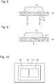
- the assembly of the first part 6a with the second part 6b defines at least one cavity 5 of the mold 2.
- This first part 6a of the mold 2 comprises an internal face that can be provided with a single cavity 3 or still several fingerprints 3 each relating to a watch element 10b to manufacture.
- These cavities 3 comprise a hollow shape defined in this flat internal face of the first piece 6a. Note that in this configuration, this mold 2 comprises as many cavities 5 as this first part 6a has imprints 3.
- the first part 6a can then comprise a circuit defined in the body of this first part 6a which is essentially arranged below each 3. Such a circuit is connected to the temperature control device 17 which is then able to generate the circulation of a cooling fluid or a heating fluid in this circuit.
- the second part 6b comprises an inner face comprising a zone 4 defined to form with said cavity 3 this cavity 5 in which cavity 5 the injectable material is injected, so as to participate in the design of said blank 10a of the watch element 10b.
- This cavity 5 defines the final shape of the watch element 10b which is at the same time made by the impression 3 but also by the corresponding zone 4 of the internal face of the second piece 6b which is then arranged opposite this impression 3 when the first and second pieces 6bs are assembled to each other.
- this second part 6b is preferably a thin plate having inner and outer faces which are flat.
- the inner face of this second part 6b is intended to be in contact with the inner face of the first part 6a when these first and second parts 6a, 6b are assembled with each other.
- the thickness of this second part 6b is preferably lower than that of the first and third parts 6a, 6c of this mold 2.
- Such a second part 6b is arranged in this mold 2 by being sandwiched between the first and third parts 6a , 6c.
- This second part 6b also comprises at least one through channel 8 connecting its inner and outer faces to each other, each through channel 8 comprising a first end opening into each corresponding cavity 5 of the mold 2 and a second end opening on the external face of this second room 6b.
- the second part 6b comprises at least as many through-channels 8 as the mold 2 comprises cavities 5.
- this second part 6b also participates in the handling of this blank 10a of the watch element 10b during the realization of the various steps leading to the manufacture of this watch element 10b, in particular when the coating is applied to this last. And finally, this second piece 6b also participates in the manipulation of the watch element 10b in preparation for its mounting on the watch component 110.
- this mold 2 also comprises a third part 6c which is intended to be assembled on the outer face of the second part 6b.
- This third part 6c comprises at least one injection circuit 7 of injectable material connected at one end to the injection device 12 and at a second end to each through channel 8 of the second part 6b.
- the third piece 6c can then include a vacuum circuit defined in the body of the third piece 6c and which is connected at one end to each channel 8 through the second part 6b and at another end to this vacuum device 16 capable of causing an air vacuum in each cavity 5 of the mold 2.
- one of the functions of the third piece 6c is to ensure the delivery of the injectable material to the through channel 8 of injection of material and participate if necessary to evacuate the cavity 5 of the mold 2.
- this watchmaking element 10b when this watchmaking element 10b is an applique it may comprise at least one foot 21 or on the contrary be devoid of it.
- the cavity 5 is formed by assembling an impression 3 included in the internal face of the first part 6a with the corresponding zone 4 of the internal face of the second part 6a. room 6b.
- this corresponding zone 4 of the inner face of the second part 6b which participates in the formation of this cavity 5 comprises an inlet 9 of the injectable material in this cavity 5.
- This inlet 9 forms the first end of the through channel 8 formed in the second part 6b which opens into the cavity 5 and whose second end is connected to the injection device 12 of injectable material through the injection circuit 7 defined in the third part 6c.
- the cavity 5 is formed by assembling an impression 3 included in the internal face of the first piece 6a with the corresponding zone 4 of the inner face of the second piece 6b provided with at least one housing provided for the formation of said at least one foot 21.
- This inner face of the second piece 6b comprises as many dwellings as the watch element 10b has feet 21.
- a housing formed in the inner face of the second piece 6b corresponds to a blind hole or to a hole having in its bottom the single inlet 9 of the injectable material in the cavity 5.
- this inlet port 9 forms the first end of the through channel 8 formed in the second part 6b which opens into the cavity 5 and whose second end is connected to the injection device 12 of injectable material via the injection circuit 7 de finished in the third room 6c. It will be noted that in this configuration, when the cavity 5 comprises one or more housings corresponding to blind holes, the inlet orifice 9 is then defined in a corresponding zone 4 of the internal face of the second component 6b of course without such dwellings.
- the portion of injectable material which is solidified in the inlet orifice 9 of the cavity 5 forms an injection point 11 which is defined to be broken especially during the separation of the watch element 10b manufactured from the second piece 6b as described later. Indeed, this injection point 11 ensures the maintenance of the watch element 10b manufactured on the second piece 6b by binding it to a core 18 formed in the mold 2.
- this core 18 comprises a first part 19b formed by the solidification of the injectable material in the through channel and / or the inlet orifice of the cavity 5, and a second part 19a formed by the solidification of the injectable material in the injection circuit formed in the third room 6c.
- the impression 3 forms the visible part of the watch element 10b such as a wall when it is mounted on a dial and the corresponding zone 4 of the second piece 6b forming as for it the connecting part of this applies with the dial from the feet of this wall or a non-visible face of the latter.
- the application device 13 of a coating on a blank 10a of the watch element 10b overmolded on the second piece 6b is able to apply / deposit a coating comprising a metal-type decorative material and / or a functional material on the outer surface of the blank 10a of the watch element 10b.
- a device 13 may comprise a printing module provided in particular with an ejection member of this decorative and / or functional material, and / or with a spraying member of such a material and / or an organ spraying a film / film comprising such material.
- the spray member may be a direct current cathode sputtering member or a high power pulsed magnetron sputtering device better known by the acronym HIPIMS for "High Power Impulse Magnetron Sputtering". It will be noted that other techniques can be implemented, such as so-called "hot transfer" of the coating on the blank.
- such a system 1 makes it possible to manufacture several watch components 110 simultaneously with a first piece 6a then comprising several impressions 3 and being able to participate with in particular the second piece 6b in obtaining a series of watch components 110 overmolded on this second piece 6b.
- these watch components 110 can be easily distributed in the automatic assembly installation of all or part of a timepiece 100.
- the first piece 6a may comprise a single footprint 3 relating to the watch element 10b to be manufactured.
- the second part 6b and the first part 6a may comprise at least one positioning element 20 (visible on the figure 6 ) of this second part 6b relative to this first part 6a so as to ensure the positioning of the corresponding zone 4 of the second part 6b opposite the corresponding footprint 3.
- this system 1 implements a method of manufacturing at least one watch element 10b, in particular an applique, intended to be attached to a watch component 110 such as a dial of a timepiece 100.
- Such a method comprises a step of producing the impression 3 in the first piece 6a from an original piece relating to the watch element 10b to be manufactured. It is understood that this step 30 is able to participate in the production of as many footprints 3 as there are clockwork elements 10b to manufacture, so that such footprints 3 are included on the same first room 6a.
- This step 30 provides the realization of a footprint 3 from an original piece otherwise called "master”. This original piece has a shape similar to that of the watch element 10b to be manufactured. Note that the implementation of this step 30 may require as many original parts as there are fingerprints 3 to achieve.
- the development step 30 comprises a design sub-step 31 of said original piece implemented from a lithography technique.
- This lithography technique is chosen from the following techniques known from the state of the art and which are not described in more detail here: optical lithography by ultraviolet projection, optical lithography by DUV projection, immersion lithography, double exposure lithography, lithography extreme ultraviolet, lithography by nanoimpression.
- This development step 30 then comprises a replication sub-step 32 of the original piece for producing the impression 3 by reproducing a negative form of the original piece.
- This sub-step 32 provides in particular the implementation of replication techniques of Ni shims or BMG (acronym "Bulk Metallic Glass") known from the state of the art and which are not described in more detail here.
- the method comprises a step 33 of making a blank 10a of the watch element 10b from an overmolding by injection of injectable material in at least one cavity 5 of the mold 2.
- This embodiment step 33 comprises a sub-step of forming the mold 2 by assembling the first, second and third parts 6a, 6b, 6c therebetween.
- This sub-step 34 provides a reversible assembly phase of the third part 6c with the second part 6b which is itself assembled to the first part 6a.
- This assembly is made in such a way as to form the cavities 5 of the mold 2 and also to ensure an optimum connection between the injection circuit 7 formed in the third piece 6c and the through-channel (s) 8 defined in the second piece 6b.
- This step 33 then comprises a molding sub-step 36 by injecting the injectable material into the cavity 5 included in the mold 2.
- This substep 36 is intended to perform an overmolding of the blank 10a 10a of the watch element 10b on the corresponding zone 4 of the inner face of the second part 6b.
- This sub-step 36 comprises an injection phase 39 in this cavity 5 of the injectable material from the injection device 12 of this material.
- the injectable material from the injection device 12 is introduced into the cavity 5 by traversing the injection circuit 7 injectable material defined in the third piece 6c and the through channel 8 included in the second piece 6b connecting this injection circuit 7 to said cavity 5.
- the injectable material then occupies the entire volume defined in the cavity 5 by overmoulding the corresponding area of the inner face of the second part 6b arranged next to the cavity 3 in optics to form this blank 10a of the watch element 10b.
- Such phases of evacuation 37 and temperature control 38 are intended to ensure a structural homogeneity of the blank 10a of the watch element 10b during its overmolding on the second part 6b in order to eliminate the presence of any defect susceptible to be present on the visible outer face of this blank 10a.
- a defect may for example reside in the presence of a weld line on the visible outer face of the blank 10a, formed following the junction of two flow streams of injectable material in the cavity 5.
- Such a line of welding is often present on blanks 10a of clockwork elements 10b relating to appliques having the form of a number 6, 8 or even 0.
- the fluid present in the cavity 5 for example a gas such as air is then discharged from the cavity 5 before the completion of the injection phase.
- the temperature of the cavity 5 is then raised to a temperature that is greater than or substantially greater than the temperature of the injectable material from the injection device 12 of this material and this, before the completion of the injection phase. Subsequently, once the injection phase 39 of the injectable material carried out that is to say completed, the cavity 5 is immediately cooled.
- the method then comprises a finalization step 40 of the watch element 10b comprising a substep of application 41 of a coating on said blank 10a of this watch element 10b overmolded on the second piece 6b.
- This sub-step 41 includes a disassembly phase 42 of the first piece 6a of the second piece 6b and a deposition phase 43 of the decorative and / or functional material on the visible outer face of the blank 10a of the watch element 10b overmolded on this second piece 6b.
- this deposition phase may provide for the application on this external face of the blank 10a of a decorative material comprising a metallic composition.
- Such a deposition phase can then be carried out using a technology using cathodic sputtering or else a high power pulsed magnetron sputtering, better known by the acronym HIPIMS for "High Power Impulse Magnetron Sputtering".
- the method then provides a removal step 44 of the watch element 10b of the second piece 6b.
- This step 44 comprises a substep 45 of breaking injection point 11 connecting said watch element 10b to the second part 6b, in preparation for its mounting on the watch component 110.
- This step 44 includes a substep of application 46 of a force on the second piece 6b and / or on the watch element 10b to cause a displacement in rotation or in translation of the watch element 10b relative to the second piece 6b.
- the force is then applied to the feet 21 of this wall from an extractor of the extraction device 22 to cause it to move in translation relative to the second part 6b. If this applique has no foot 21, the force is then applied to the visible face of the watch element 10b in order to generate its displacement in rotation relative to the second part 6b and cause the injection point to break.
- this wall light is devoid of feet 21 it is then fixed on this dial at the corresponding location from for example this hot melt glue.
Priority Applications (6)
| Application Number | Priority Date | Filing Date | Title |
|---|---|---|---|
| EP18165061.5A EP3547042A1 (de) | 2018-03-29 | 2018-03-29 | Herstellungsverfahren und -system mindestens eines uhrenelements zum anbringen auf einer uhrenkomponente einer uhr |
| PCT/EP2019/056986 WO2019185422A1 (fr) | 2018-03-29 | 2019-03-20 | Procédé et système de fabrication d'au moins un élément horloger destiné à être rapporté sur un composant horloger d'une pièce d'horlogerie |
| US16/975,272 US11964411B2 (en) | 2018-03-29 | 2019-03-20 | Method and system for manufacturing at least one timepiece element intended to be mounted on a timepiece component of a timepiece |
| JP2020544746A JP6964198B2 (ja) | 2018-03-29 | 2019-03-20 | 計時器用コンポーネントにマウントされるように意図された少なくとも1つの計時器用要素を製造する方法及びシステム |
| EP19712188.2A EP3776094A1 (de) | 2018-03-29 | 2019-03-20 | Verfahren und system zur herstellung von mindestens einem uhrenelement, das zur montage auf einem uhrenbauteil einer uhr vorgesehen ist |
| CN201980023950.7A CN111971627B (zh) | 2018-03-29 | 2019-03-20 | 用于制造至少一个钟表元件的方法和系统 |
Applications Claiming Priority (1)
| Application Number | Priority Date | Filing Date | Title |
|---|---|---|---|
| EP18165061.5A EP3547042A1 (de) | 2018-03-29 | 2018-03-29 | Herstellungsverfahren und -system mindestens eines uhrenelements zum anbringen auf einer uhrenkomponente einer uhr |
Publications (1)
| Publication Number | Publication Date |
|---|---|
| EP3547042A1 true EP3547042A1 (de) | 2019-10-02 |
Family
ID=61868257
Family Applications (2)
| Application Number | Title | Priority Date | Filing Date |
|---|---|---|---|
| EP18165061.5A Withdrawn EP3547042A1 (de) | 2018-03-29 | 2018-03-29 | Herstellungsverfahren und -system mindestens eines uhrenelements zum anbringen auf einer uhrenkomponente einer uhr |
| EP19712188.2A Pending EP3776094A1 (de) | 2018-03-29 | 2019-03-20 | Verfahren und system zur herstellung von mindestens einem uhrenelement, das zur montage auf einem uhrenbauteil einer uhr vorgesehen ist |
Family Applications After (1)
| Application Number | Title | Priority Date | Filing Date |
|---|---|---|---|
| EP19712188.2A Pending EP3776094A1 (de) | 2018-03-29 | 2019-03-20 | Verfahren und system zur herstellung von mindestens einem uhrenelement, das zur montage auf einem uhrenbauteil einer uhr vorgesehen ist |
Country Status (5)
| Country | Link |
|---|---|
| US (1) | US11964411B2 (de) |
| EP (2) | EP3547042A1 (de) |
| JP (1) | JP6964198B2 (de) |
| CN (1) | CN111971627B (de) |
| WO (1) | WO2019185422A1 (de) |
Families Citing this family (2)
| Publication number | Priority date | Publication date | Assignee | Title |
|---|---|---|---|---|
| EP4198644A1 (de) * | 2021-12-20 | 2023-06-21 | Rubattel et Weyermann S.A. | Verfahren zur herstellung eines zifferblatts |
| EP4198643A1 (de) * | 2021-12-20 | 2023-06-21 | Rubattel et Weyermann S.A. | System zur herstellung mindestens eines dreidimensionalen elements auf einem verkleidungselement einer uhr |
Citations (2)
| Publication number | Priority date | Publication date | Assignee | Title |
|---|---|---|---|---|
| CH354028A (fr) * | 1959-04-24 | 1961-04-30 | Lapidor Sa | Procédé de fabrication de cadrans d'horlogerie et outillage pour la mise en oeuvre de ce procédé |
| CH395870A (fr) * | 1962-07-24 | 1964-07-31 | Huguenin & Cie | Procédé de fabrication d'un cadran d'horlogerie |
Family Cites Families (11)
| Publication number | Priority date | Publication date | Assignee | Title |
|---|---|---|---|---|
| CH557562A (en) | 1968-11-22 | 1974-12-31 | Moulding one piece dials | |
| GB2027636B (en) * | 1978-03-29 | 1982-03-17 | Shortland Bowen Instr | Method of forming raised figures on dial plate |
| JP2544553Y2 (ja) * | 1993-01-21 | 1997-08-20 | リズム時計工業株式会社 | 精密機器用成形部品 |
| JPH08182514A (ja) * | 1994-12-27 | 1996-07-16 | Casio Comput Co Ltd | インサート成形バンドおよびその製造方法並びに該バンドに用いるインサート金属ピース |
| CN100577391C (zh) | 2005-02-25 | 2010-01-06 | 复旦大学 | 聚二甲基硅氧烷阳模原位聚合制备有机玻璃微流控芯片的方法 |
| JP5007562B2 (ja) * | 2006-12-27 | 2012-08-22 | セイコーエプソン株式会社 | 時計用文字板の製造方法、時計用文字板および時計 |
| WO2008100583A1 (en) | 2007-02-13 | 2008-08-21 | Yale University | Method for imprinting and erasing amorphous metal alloys |
| EP2273324A1 (de) | 2009-07-06 | 2011-01-12 | ETA SA Manufacture Horlogère Suisse | Verfahren zur Herstellung eines verzierten Reliefteils |
| EP2579108B1 (de) | 2011-10-04 | 2014-05-14 | ETA SA Manufacture Horlogère Suisse | Verfahren zur Herstellung und Gestaltung einer durchsichtigen Uhrenkomponente |
| DE102013110702B4 (de) * | 2013-09-27 | 2019-11-14 | Leonhard Kurz Stiftung & Co. Kg | Verfahren, Formeinsatz und Spritzgussform zum Herstellen eines Kunststoffformteils |
| CN107160632A (zh) | 2017-05-11 | 2017-09-15 | 东莞智昊光电科技有限公司 | Led支架及该led支架的制造方法和制造设备 |
-
2018
- 2018-03-29 EP EP18165061.5A patent/EP3547042A1/de not_active Withdrawn
-
2019
- 2019-03-20 CN CN201980023950.7A patent/CN111971627B/zh active Active
- 2019-03-20 EP EP19712188.2A patent/EP3776094A1/de active Pending
- 2019-03-20 JP JP2020544746A patent/JP6964198B2/ja active Active
- 2019-03-20 US US16/975,272 patent/US11964411B2/en active Active
- 2019-03-20 WO PCT/EP2019/056986 patent/WO2019185422A1/fr unknown
Patent Citations (2)
| Publication number | Priority date | Publication date | Assignee | Title |
|---|---|---|---|---|
| CH354028A (fr) * | 1959-04-24 | 1961-04-30 | Lapidor Sa | Procédé de fabrication de cadrans d'horlogerie et outillage pour la mise en oeuvre de ce procédé |
| CH395870A (fr) * | 1962-07-24 | 1964-07-31 | Huguenin & Cie | Procédé de fabrication d'un cadran d'horlogerie |
Also Published As
| Publication number | Publication date |
|---|---|
| JP6964198B2 (ja) | 2021-11-10 |
| CN111971627A (zh) | 2020-11-20 |
| US11964411B2 (en) | 2024-04-23 |
| WO2019185422A1 (fr) | 2019-10-03 |
| JP2021515204A (ja) | 2021-06-17 |
| CN111971627B (zh) | 2022-08-30 |
| EP3776094A1 (de) | 2021-02-17 |
| US20200398465A1 (en) | 2020-12-24 |
Similar Documents
| Publication | Publication Date | Title |
|---|---|---|
| WO2019185422A1 (fr) | Procédé et système de fabrication d'au moins un élément horloger destiné à être rapporté sur un composant horloger d'une pièce d'horlogerie | |
| EP2273324A1 (de) | Verfahren zur Herstellung eines verzierten Reliefteils | |
| EP3168058B1 (de) | Herstellungsverfahren eines werkstücks aus metall mit mindestens einem motiv mit optischen täuschungselementen | |
| EP3727941B1 (de) | Verkleidungselement für die externe säule eines fahrzeugs sowie herestellungsverfahren für ein derartiges element | |
| CH714845A2 (fr) | Procédé et système de fabrication d'au moins un élément horloger destiné à être rapporté sur un composant horloger d'une pièce d'horlogerie. | |
| KR100933922B1 (ko) | 휴대폰 또는 디지털 카메라용 플래시렌즈 일체형 데코패널의 제조방법 및 이에 의해 제조된 플래시렌즈 일체형 데코패널 | |
| EP3526645B1 (de) | Herstellungsverfahren eines reliefdekors, das mit einem clip ausgestattet ist | |
| EP4198643A1 (de) | System zur herstellung mindestens eines dreidimensionalen elements auf einem verkleidungselement einer uhr | |
| FR2967372A1 (fr) | Procede de fabrication d'un miroir reflechissant | |
| CH719282A2 (fr) | Système de réalisation d'au moins un élément tridimensionnel sur un élément d'habillage d'une pièce d'horlogerie. | |
| EP4198644A1 (de) | Verfahren zur herstellung eines zifferblatts | |
| CH719279A2 (fr) | Procédé de fabrication d'un cadran. | |
| EP1538493A1 (de) | Emailliertes Zifferblatt mit eingeschlagenen Füssen und Herstellungsverfahren dafür | |
| FR3139495A1 (fr) | Procédé de moulage de panneau de carrosserie | |
| CH716192A2 (fr) | Composant en céramique destiné à être rapporté sur un cadran de montre et procédé de fabrication d'un tel composant. | |
| EP1538492B1 (de) | Emailliertes Zifferblatt mit Füsse und sein Herstellungsverfahren dafür | |
| EP3288699B1 (de) | Verfahren zur herstellung eines modells für feinguss | |
| CH713027B1 (fr) | Procédé de fabrication d'un décor en relief muni d'une attache | |
| CH707415A2 (fr) | Procédé de fabrication d'un dispositif électronique portable flexible. | |
| CH701442A2 (fr) | Procédé de fabrication d'une pièce en relief décorée. | |
| CH716967A2 (fr) | Procédé de fabrication d'un composant horloger et composant obtenu selon ce procédé. | |
| CH715954B1 (fr) | Procédé de décoration d'une pièce mécanique. | |
| FR3106296A1 (fr) | Procédé de fabrication d’une pièce moulée comprenant une étape de recuit et outil pour la mise en œuvre d’un tel procédé | |
| CH696987A5 (fr) | Cadran émaillé avec pieds fixes et son procédé de fabrication | |
| FR3035614A1 (fr) | Procede de fabrication d'une piece decorative, film et piece decorative correspondants |
Legal Events
| Date | Code | Title | Description |
|---|---|---|---|
| PUAI | Public reference made under article 153(3) epc to a published international application that has entered the european phase |
Free format text: ORIGINAL CODE: 0009012 |
|
| AK | Designated contracting states |
Kind code of ref document: A1 Designated state(s): AL AT BE BG CH CY CZ DE DK EE ES FI FR GB GR HR HU IE IS IT LI LT LU LV MC MK MT NL NO PL PT RO RS SE SI SK SM TR |
|
| AX | Request for extension of the european patent |
Extension state: BA ME |
|
| 17P | Request for examination filed |
Effective date: 20200402 |
|
| RBV | Designated contracting states (corrected) |
Designated state(s): AL AT BE BG CH CY CZ DE DK EE ES FI FR GB GR HR HU IE IS IT LI LT LU LV MC MK MT NL NO PL PT RO RS SE SI SK SM TR |
|
| STAA | Information on the status of an ep patent application or granted ep patent |
Free format text: STATUS: THE APPLICATION IS DEEMED TO BE WITHDRAWN |
|
| 18D | Application deemed to be withdrawn |
Effective date: 20200203 |