EP3546155B1 - Dispositif de soins personnels tel qu'un rasoir électrique - Google Patents
Dispositif de soins personnels tel qu'un rasoir électrique Download PDFInfo
- Publication number
- EP3546155B1 EP3546155B1 EP18164823.9A EP18164823A EP3546155B1 EP 3546155 B1 EP3546155 B1 EP 3546155B1 EP 18164823 A EP18164823 A EP 18164823A EP 3546155 B1 EP3546155 B1 EP 3546155B1
- Authority
- EP
- European Patent Office
- Prior art keywords
- display
- housing
- foil
- inner housing
- adhesive
- Prior art date
- Legal status (The legal status is an assumption and is not a legal conclusion. Google has not performed a legal analysis and makes no representation as to the accuracy of the status listed.)
- Active
Links
- 239000011888 foil Substances 0.000 claims description 175
- 239000000853 adhesive Substances 0.000 claims description 41
- 230000001070 adhesive effect Effects 0.000 claims description 41
- 239000012790 adhesive layer Substances 0.000 claims description 40
- 239000006260 foam Substances 0.000 claims description 21
- 239000010410 layer Substances 0.000 claims description 17
- 239000000463 material Substances 0.000 claims description 17
- 239000007788 liquid Substances 0.000 claims description 12
- 238000007789 sealing Methods 0.000 claims description 11
- 238000000034 method Methods 0.000 claims description 9
- 238000004519 manufacturing process Methods 0.000 claims description 8
- 229920003023 plastic Polymers 0.000 claims description 8
- 239000004033 plastic Substances 0.000 claims description 8
- 238000011282 treatment Methods 0.000 claims description 7
- 239000004698 Polyethylene Substances 0.000 claims description 5
- 229920000573 polyethylene Polymers 0.000 claims description 5
- 239000003086 colorant Substances 0.000 claims description 4
- 229920001971 elastomer Polymers 0.000 claims description 4
- 238000003892 spreading Methods 0.000 claims description 4
- 230000007480 spreading Effects 0.000 claims description 4
- 230000004913 activation Effects 0.000 claims description 2
- -1 polyethylene Polymers 0.000 claims description 2
- 230000000063 preceeding effect Effects 0.000 claims 1
- 239000000306 component Substances 0.000 description 15
- 238000004026 adhesive bonding Methods 0.000 description 13
- 230000010355 oscillation Effects 0.000 description 7
- 230000033001 locomotion Effects 0.000 description 6
- 230000008569 process Effects 0.000 description 6
- 239000007779 soft material Substances 0.000 description 6
- 239000003292 glue Substances 0.000 description 5
- 238000013532 laser treatment Methods 0.000 description 5
- 238000005286 illumination Methods 0.000 description 3
- 230000001771 impaired effect Effects 0.000 description 3
- 238000010330 laser marking Methods 0.000 description 3
- 239000011159 matrix material Substances 0.000 description 3
- 238000003860 storage Methods 0.000 description 3
- XLYOFNOQVPJJNP-UHFFFAOYSA-N water Substances O XLYOFNOQVPJJNP-UHFFFAOYSA-N 0.000 description 3
- 229920005830 Polyurethane Foam Polymers 0.000 description 2
- 238000001994 activation Methods 0.000 description 2
- 238000000149 argon plasma sintering Methods 0.000 description 2
- 238000005452 bending Methods 0.000 description 2
- 230000008901 benefit Effects 0.000 description 2
- 230000005540 biological transmission Effects 0.000 description 2
- 238000004140 cleaning Methods 0.000 description 2
- 230000002950 deficient Effects 0.000 description 2
- 238000004880 explosion Methods 0.000 description 2
- 239000002991 molded plastic Substances 0.000 description 2
- 230000007935 neutral effect Effects 0.000 description 2
- 210000000988 bone and bone Anatomy 0.000 description 1
- 230000001413 cellular effect Effects 0.000 description 1
- 238000004891 communication Methods 0.000 description 1
- 238000001816 cooling Methods 0.000 description 1
- 239000008358 core component Substances 0.000 description 1
- 238000009792 diffusion process Methods 0.000 description 1
- 238000005187 foaming Methods 0.000 description 1
- 239000000499 gel Substances 0.000 description 1
- 239000000203 mixture Substances 0.000 description 1
- 238000000465 moulding Methods 0.000 description 1
- 238000004806 packaging method and process Methods 0.000 description 1
- 239000004814 polyurethane Substances 0.000 description 1
- 238000003825 pressing Methods 0.000 description 1
- 230000005855 radiation Effects 0.000 description 1
- 238000003466 welding Methods 0.000 description 1
Images


Classifications
-
- B—PERFORMING OPERATIONS; TRANSPORTING
- B26—HAND CUTTING TOOLS; CUTTING; SEVERING
- B26B—HAND-HELD CUTTING TOOLS NOT OTHERWISE PROVIDED FOR
- B26B19/00—Clippers or shavers operating with a plurality of cutting edges, e.g. hair clippers, dry shavers
- B26B19/38—Details of, or accessories for, hair clippers, or dry shavers, e.g. housings, casings, grips, guards
Definitions
- the present invention relates to a personal care device, in particular a hair removal device such as an electric shaver, comprising a housing with a working head attached thereto, said housing including an inner housing and an outer housing, and a display including a light source accommodated in the inner housing to emit light through transparent portions of said inner and outer housings, said display further including a display foil having portions of different transparency and/or different colors forming display symbols, said display foil being sandwiched between said transparent portions of the inner and outer housings.
- the present invention further relates to a method of manufacturing such a personal care device.
- Electric shavers and other hair removal devices such as epilators usually have one or more cutter elements driven by an electric drive unit in an oscillating manner where the cutter elements reciprocate under a shear foil, wherein such cutter elements or undercutters may have an elongated shape and may reciprocate along their longitudinal axis.
- Other types of electric shavers use rotatory cutter elements which may be driven in an oscillating or a continuous manner.
- Said electric drive unit may include an electric motor or a magnetic-type linear motor, wherein the drive unit may include a drive train having elements such as an elongated drive transmitter for transmitting the driving motion of the motor to the cutter element, wherein said motor may be received within the handle portion of the shaver.
- Such power source may be an electric power storage such as a battery or an accumulator.
- the housing accommodating the electric motor and/or electric power source often includes an elongated base element closed by a cover element to allow for mounting and accommodating the electronic components inside the housing.
- a seal is provided between the base element and the cover element, wherein such seal may include a sealing ring extending between surfaces of the base element and the cover element facing each other.
- Such sealing of the housing is also necessary so as to protect other electronic components from liquids and moisture.
- personal care devices often include a display device for displaying various information to a user.
- Such display may include symbols indicating a battery's charging status, a cleaning status, wear and tear necessitating, for example, replacement of the tool head, a level of an application liquid reservoir or other types of information such as treatment instructions, speed modes, user modes or styling modes.
- Such display devices may include at least one light source such as an LED to emit light from the interior of the housing through a transparent portion of the housing, wherein such light may be guided through a display foil provided with more and less transparent portions and/or portions of different colors to form the aforementioned symbols which are illuminated by the light guided through said display foil. While the light source and supplying and controlling elements connected thereto such as an electronic circuit board are received inside the housing to protect them against moisture, said display foil is sometimes positioned outside the sealed housing container to provide for a more brilliant illumination of the displaying symbols richer in contrast.
- a light source such as an LED to emit light from the interior of the housing through a transparent portion of the housing
- a display foil provided with more and less transparent portions and/or portions of different colors to form the aforementioned symbols which are illuminated by the light guided through said display foil.
- said display foil may be positioned outside an inner housing which is sealed against moisture or liquids, but inside an outer housing encompassing or surrounding said inner housing so that the aforementioned display foil is sandwiched between the inner and outer housings.
- Such two-shell or multiple-shell structure of the housing is sometimes desired so as to hide the functional structure of the inner housing and to provide for good handling, aesthetic appearance and modular configuration of different types of devices.
- Each of the inner and outer housings may be individually adapted to different functions.
- the inner housing may form a functional platform for accommodating electronic components protected against moisture and positioning drivetrain elements and supporting the working head
- the outer housing may fulfill other needs such as forming an ergonomic handle with an organic shape and an anti-slippery surface, or an attractive outer appearance.
- Such outer housing is sometimes not sealed against moisture or liquids or foam or gel which therefore may get contact to the display foil arranged between the outer and inner housings.
- Such moisture getting contact to the display foil may impair visibility of the display symbols or, even worse, may harm the function of the display foil due to, for example, dissolving the borders between transparent and opaque portions.
- the display foil when positioning the display foil between inner and outer housing portions, it is sometimes difficult to exactly align the symbols of the display foil with the light source accommodated in the interior of the inner housing, as manufacturing tolerances may cause misalignment of the display foil. Even when there are only small misalignments, illumination of the symbols may be severely impaired due to light diffusion or stray light or shadowing. As there are usually a plurality of symbols positioned rather close to each other, the light sources are also arranged in a sort of rather dense matrix so that even small misalignments may cause light emitted from a light source associated with a first symbol to stray and scatter onto a second symbol.
- a personal care device of the aforementioned type is shown, for example, by US 2009/0025229 A1 which discloses a drive unit for the cutter elements of an electric shaver, wherein the drive unit includes transmitter pins extending from the shaver housing towards the shaver head.
- a similar device is known from US 7,841,090 B2 .
- a more particular objective underlying the invention is to provide for cost-sensitive, easy manufacturing of personal care devices such as a hair removal device as electric shavers having a brilliant display for displaying information and sufficiently sealed against liquids.
- a further objective underlying the invention is to provide for an improved hair removal device such as e.g. a shaver having a sealed container housing for accommodating electric components such as an electric motor and/or an electric power source, and a display rich in contrast and providing for good visibility.
- an improved hair removal device such as e.g. a shaver having a sealed container housing for accommodating electric components such as an electric motor and/or an electric power source, and a display rich in contrast and providing for good visibility.
- an objective underlying the present invention is to combine an easily visible display with sealing of the personal care device's housing and protection of the display against moisture even when there are tolerances in shape and/or dimensions of the housing elements to be connected and/or variations in the mounting forces pressing the housing elements against each other due to tolerances and/or mistakes in the assembling process.
- a personal care device as mentioned above having a sealing of the display foil to both the inner and outer housing elements to protect the display foil against liquids and moisture.
- the display foil may be glued to both the inner and outer housing by means of an adhesive on each of opposite sides of the display foil. Due to such adhesion of the display foil to the outer side of the inner housing and the inner side of the outer housing, water or other liquids and moisture or foam or gel are prevented from creeping onto the display foil surface, thereby preventing visibility from being impaired or the display foil from becoming defective.
- an adhesive foam such as PE foam or PU foam may be used as adhesive for glueing the display foil to the inner or outer housing.
- the display foil may be provided with the symbols to be illuminated by means of, for example, laser treatment of the display foil, after having attached the display foil to the inner housing. Applying the symbols to the foil after having fixed the foil to the inner housing helps in avoiding misalignment of the symbols relative to the inner housing and components received therein such as the light source.
- the inner housing may be provide with opaque shading fences on the interior side of the inner housing for restricting light emitted by a light source associated with a transparent housing portion aligned with a display symbol to be transmitted only to said display symbol and prevent other symbols from being illuminated by stray light or scattered light originating from such light source.
- a personal care device to seal the display foil, which is arranged between the inner and outer housings, to the inner surface of the outer housing as well to the outer surface of the inner housing. More particularly, the display foil is glued to both the inner and outer housings by means of an adhesive on each of the opposite major surfaces of the display foil so that the outer housing is glued to the inner housing via said display foil. Due to such gluing of both surfaces of the display foil to the inner and outer housings, water or other liquids and moisture are prevented from creeping onto the displaying surface of the display foil what prevents visibility of the display symbols from being impaired and the display foil from becoming defective.
- said adhesive may form at least a closed sealing loop surrounding the area of the display foil in which the display symbols are arranged, wherein such closed sealing loop may run along the outer edges of the display foil.
- closed sealing loop formed by the adhesive may be provided on each of opposite sides of the display foil so central areas on both sides of the display foil may be left open.
- at least one of the major surfaces of the display foil may be fully covered by adhesive and fully glued to the respective housing element so that the display foil, at least on one side, is in full contact with the housing.
- the adhesive may form a transparent adhesive layer covering at least a major portion of the display foil including the display area in which the display symbols are arranged, whereas on the opposite other side of the display foil the adhesive may form an adhesive layer having a window leaving open or leaving uncovered the display symbols.
- the display foil is not covered by adhesive and may be spaced apart from the transparent housing portion covering the display foil.
- Glueing at least one side of the display foil substantially completely to the housing i.e. the complete surface area of said at least one side or at least a major portion of the surface area of said side is covered by adhesive and glued to said housing, helps in maintaining the desired shape of the display foil and prevents the display foil from corrugating or undulating or wrinkling or other undesired deformations.
- Both sides of the display foil may be substantially completely glued to the inner and outer housings, wherein in such case a transparent adhesive is used to glue the display foil to the inner and outer housings so that light may shine through the transparent adhesive layers, in particular in the area of the display symbols.
- windowed adhesive layer may be provided on a top surface of the display unit to fix the display foil to the outer housing.
- windowed adhesive layer may be provided on a bottom side of the display foil to connect the display foil to the inner housing.
- Such adhesive layer having a window portion leaving open the display foil's area in which the display symbols are arranged may consist of or include an opaque adhesive material.
- Use of such opaque adhesive material forming a window frame surrounding the display area of the display foil may prevent scattered light from illuminating other portions than the display area and thus, may improve visibility of the illuminated symbols.
- the adhesive for glueing the display foil to the inner and/or outer housing may include an adhesive foam and/or be made from a foamy material.
- a polyurethane (PU) or a polyethylene (PE) foam may be used to fixedly attach the display unit to the inner housing or to the outer housing.
- Adhesive foam may be advantageous so as to compensate for tolerances in the distance of the inner surface of the outer housing from the outer surface of the inner housing and/or to compensate for movements of the inner and outer housings relative to each other which may occur, for example, due to bending of the housing and/or gripping the housing with excessive forces and/or for avoiding the generation of bubbles between two glue layers .
- the adhesive foam may be elastic and/or deformable to allow for such compensation.
- such adhesive foam may easily compensate for uneven portions of the housings' surface and to provide for a smooth surface holding the display foil.
- the aforementioned adhesive layer having a window leaving open the display foil's area in which the display symbols are provided may be formed from such adhesive foam.
- the outer housing may be composed of a plurality of housing parts, wherein an outer housing display part to which the display foil is attached, may form a substantially plate-like insert received in a window of another outer housing part which helps in avoiding transmission of forces applied to said other housing part to said outer housing display part.
- the outer housing display part may form a window pane to be inserted into the window frame formed by said other housing part.
- said outer housing display part forming the aforementioned insert may be inserted into the window of the other housing part from an inner side of the outer housing so that the outer housing display part may stick to the display foil even when the other housing part having said window is moved away from the display foil.
- the other outer housing part having said window may, with an edge portion of the window, overlay the outer housing display part from an outside thereof.
- the display foil may be provided with the display symbols after having been attached to the inner housing. More particularly, when manufacturing and/or assembling the personal care device, a plain display foil not yet having the display symbols may be glued onto the outer surface of the inner housing. After having attached the display foil onto the inner housing by means of glueing, a marking treatment may be applied to the display foil so as to generate the display symbols desired. More particularly, a laser treatment process may be used so as to provide the display foil attached to the inner housing with the desired symbols.
- the display foil may include a laser-active layer.
- a transparent foil may be used having a laser-active layer becoming opaque when applying laser light thereon.
- the laser-active layer may be originally opaque, for example black, wherein the laser-active layer may be configured to become transparent in the portions subject to the laser beam.
- Provision of the display symbols after having attached the display foil to the inner housing is not only advantageous in terms of exact alignment irrespective of tolerances in positioning the foil onto the housing, but also allows for easy logistics avoiding storage of different display foils preconfigured for different models of the personal care device, thus reducing the number of different parts needed, and making delivery of the parts needed for assembling an embodiment just in time easier.
- the outer housing may be glued to the display foil.
- the manufacturing process may include the following three steps executed one after the other with optional other intermediate treatment steps therebetween: gluing a plain display foil onto the inner housing, marking the display foil with the symbols to be displayed and then glueing the outer housing onto the marked display foil.
- Said optional intermediate steps may include, for example, a heat application step for expediting hardening of the adhesive, or a cooling step after laser marking the display foil.
- the inner housing may be formed to include transparent portions and opaque portions. More particularly, the inner housing may include a transparent portion aligned with and positioned below a display symbol of the display foil, and a non-transparent portion surrounding said transparent portion, said non-transparent portion may have a ring-shape and/or may form a shadowing fence preventing light going through the transparent portion from spreading into other portions neighboring the display symbol.
- the inner housing may be formed as a two-component or multiplecomponent part comprising portions of different materials.
- the inner housing may be a molded plastic part made from two different plastic components one of which is transparent and another one is opaque.
- the inner housing may have a plurality of transparent portions aligned with the position of the display symbols, wherein each of said transparent housing portions may be surrounded, at least in part, by non-transparent housing portions.
- Said non-transparent housing portions separating the transparent housing portions from each other may form a net-like or grid-like, opaque structure separating the transparent portions of the inner housing aligned with the display symbols from each other.
- the transparent portions of the inner housing may be formed from a transparent hard-plastic material component, whereas the non-transparent, grid-like structure may be formed from an opaque soft-material plastic component.
- a shadowing fence structure also may be provided between the inner surface of the inner housing and the light source. More particularly, such shadowing fence structure on the inner side of the inner housing may include at least one non-transparent sleeve surrounding the at least one light source and extending from the light source to the inner surface of the inner housing, wherein a longitudinal axis of such sleeve may extend substantially perpendicular to the inner housing and/or to the display foil and/or substantially parallel to the main axis of emission of the light source.
- a plurality of such sleeve-like shadowing fences may be provided so as to form light pipes directing light from each light source to the display symbol associated therewith and to prevent such light from spreading towards another display symbol.
- the sleeve-like shadowing fences may form a grid-like or net-like structure of opaque material having light channels formed by recesses in the material and going from a light source to the respective display symbol, more particularly the transparent portion of the inner housing associated with such display symbol.
- the light sources may be arranged on a common circuit board for supplying electric energy to the light sources and/or controlling the light sources.
- the sleeve-like shadow fences forming light pipes may extend between such circuit board and the inner housing, wherein the shadowing fence structure may be attached to the circuit board and/or to the inner housing in a fixedly manner, for example by means of glueing or by means of press-fitting contact.
- said shadowing fence structure may be formed by a foamy material allowing for full contact of the surface of the circuit board and/or the inner housing irrespective of uneven sections thereof. More particularly, the shadowing fence structure may be formed by a sponge material such as cellular rubber or sponge rubber that may self-adapt its contour to the contact surface.
- the inner housing may form a sealed, in particular water-proof container in which the motor and/or batteries or accumulators or other power sources and/or an electronic control unit for controlling the motor and the light sources of the display may be received and protected against liquids and moisture, wherein said container may have a barrel structure and being formed by an elongated pot or cup having a closed bottom and an open top side, wherein the motor, an electronic control unit and batteries may be completely received within such cup element of the inner housing which, at its open top side, may be closed by means of a cover element which may form the front face of the barrel-like container forming the inner housing.
- the barrel-like container forming the inner housing may have a two-piece structure comprising only two pieces, i.e. the aforementioned cup element and the cover element.
- Such two-piece structure of the inner housing considerably reduces sealing efforts necessary to make the container waterproof.
- Said cup element may include the transparent portion(s) aligned with the display foil.
- the aforementioned cup-shaped base element may have an elongated configuration extending substantially over the entire length of the inner housing and may have a length corresponding to at least 80% or 90% of the inner housing and/or of the handle, whereas the cover element may have a length of smaller than 20% or smaller than 10% of the inner housing's length and/or the handle's length.
- Such cover element may have a disklike or plate like configuration, wherein it my have a slightly dome-shaped or convex contour.
- the connector for connection to the shaver head's support structure may be provided on the aforementioned cover element.
- the cover element and the cup element of the inner housing may be rigidly connected to each other, wherein various known types of connection techniques such as form-fitting, screwing, welding, glueing and/or snap-fitting may be used.
- a support frame to which the aforementioned components are attached may be inserted into the cup element and may be held there in place, wherein for example a slideable guide element such as a guiding groove and/or guiding projections may be provided.
- Such support frame may be formed by or include a circuit board bearing the light source(s) and/or forming part of the electronic control unit.
- the inner housing may have only one opening which may be an opening in the cover element through which the shaft protrudes.
- second opening may be avoided by means of integrating the charging connectors into the inner housing, for example by means of molding charging pins to be an integral part of the inner housing.
- the inner housing and/or outer housing may include a soft material portion allowing to be deformed so as to activate switches positioned inside the inner housing.
- the outer housing also may have soft material portions and/or a recess or opening through which the soft material portion of the inner housing can be deformed.
- the outer housing may have a two-piece or three-piece or multiple-piece shell structure comprising a plurality of shell elements that can be connected with each other and cover different portions of the inner housing.
- the outer housing may comprise two shell elements extending on opposite sides of the inner housing and connectable to each other.
- Such shell elements may have a substantially - roughly speaking - flute-like or chute-like contour so that the two shell elements together may surround the inner housing substantially completely.
- the outer housing may further include a ring element to be connected with at least one of the aforementioned shell elements.
- a ring element may help in forming a rigid, strong outer housing structure, wherein such ring element may be positioned at an end portion of the housing facing the shaver head. More particularly, such ring element may surround the shaft and may have an inner diameter which is significantly smaller than the maximum diameter of the inner housing.
- the handle When considering the handle in its entirety, the handle may have an elongated shape the cross-section of which may substantially continuously increase from a bottom face of the handle to a top face of the handle opposite to said bottom face of the handle. In other words, the cross-section of the handle may continuously increase towards the shaver head.
- the cross-sectional shape may vary, wherein such cross-sectional shape may be substantially rounded and/or circular and/or elliptical and/or oval. "Substantially continuosly" does not exclude some portions such as the display portion or an operating key portion where the cross-section does not increase. Nevertheless, when considering the larger proportions, the handle's cross-section may increase from a bottom end portion to a top end portion.
- a drive transmitter may include a shaft or shaft-like elongated drive element extending from the handle into the interior of the shaver head.
- a crank arm may be attached to the shaft, wherein such crank arm may be positioned within the shaver head and/or may support at least one drive pin for driving the cutter element.
- drive pin may extend substantially parallel to the shaft and may be fixedly attached to the crank arm to extend eccentric with regard to the shaft axis.
- shaver 1 may have a shaver housing 300 forming a handle 2 for holding the shaver, which handle may have different shapes such as - roughly speaking - a substantially cylindrical shape or box shape or bone shape allowing for ergonomically grabbing or holding the shaver, wherein such shaver handle 2 has a longitudinal axis 20 due to the elongated shape of the handle, cf. Fig. 1 .
- the handle 2 may have a cross-sectional shape which is rounded or circular or oval or elliptical, wherein mixtures of those shapes are possible. Irrespectible of the cross-sectional shape, the cross-section may continuously increase from one end of the handle to the other one thereof.
- a electric shaver head 3 is attached to the handle 2, wherein the shaver head 3 may be slewably supported about a swiveling axis 7 and about a tilting axis 11 which swiveling and tilting axes 7 and 11 may extend substantially perpendicular to each other and perpendicular to the aforementioned longitudinal handle axis 20.
- the swivel axis 7 may extend parallel to such main axis 40, whereas the tilting axis 11 may extend perpendicular to such main axis 40.
- Such main axis 40 may be considered to extend in parallel to the larger side surfaces of the shaver head 3 and/or in parallel with a longitudinal axis of the elongated cutter elements 4 and/or in parallel with a cutter oscillation axis 8 and/or substantially perpendicular to the longitudinal handle axis 20.
- the shaver head 3 may include a pair of elongated cutter units 100 each comprising an elongated cutter element 4 that can be driven in a reciprocating manner along reciprocating axis 8 which may extend parallel to the aforementioned main axis 40. Said cutter elements 4 may cooperate with and reciprocate under shear foils 5 covering said cutter elements 4.
- the shaver head 3 is supported onto the handle 2 by means of a support structure 30.
- an elongated drive transmitter may extend from the handle 2 into the shaver head 3 so as to connect the cutter element 4 to a motor 93 which may be accomodated in the interior of the handle 2.
- a motor 93 which may be accomodated in the interior of the handle 2.
- Such elongated drive transmitter 9 may include a shaft 90 which may be driven to rotate in a reciprocating manner, i.e. to rotate back and forth by a certain degree.
- a crank element may be rotatorily fixed to said shaft 90 and accomodated inside the shaver head 3.
- Such crank element may rigidly support a drive pin for each of said cutter elements 4.
- Said crank element in a neutral position of the shaft 90 may extend transverse to the longitudinal axis of the elongated cutter element 4 so that the drive pin moves back and forth along the longitudinal axis of the cutter element 4. More particularly, such drive pin executes a movement along a segment of a circle. However, as the rotational oscillation has a limited amplitude and the circular segment is tangential to the longitudinal axis of the cutter element 4, such movement may be considered to approximate a linear movement along the cutter element's longitudinal axis.
- the housing 300 forming the handle 2 may have a two-shell structure comprising an inner housing 301 and an outer housing 302 (including parts 305, 304, 302d) surrounding said inner housing 301.
- the inner housing 301 accomodates the aforementioned motor 93 and furthermore, an electrical storage such as batteries or an accumulator, and an electronic control unit, cf. Fig. 3 , wherein the inner housing 301 may form a water-tight container protecting such components from liquids and moisture.
- the inner housing 301 may have an elongated barrel-like structure including a cup-shaped or pot-like base element 306 having a closed bottom and an open top face, wherein such base element may extend substantially over the entire length of the handle 2, cf. Fig. 2 and 3 .
- the base element 306 is closed, at its open top side, by a cover element 307 which may have a plate-like or slightly dome-like shape and, when closing the base element 306, forms a front face side of the inner housing 301 facing the shaver head 3.
- the aforementioned cover element 307 includes an opening through which the shaft 90 penetrates the housing, wherein the cover element 307 is sealed, by means of appropriate seals, against said shaft 90 and against the cover element 307 so that the inner housing 301 forms a waterproof container.
- charging connections such as charging pins 310 may protrude from the bottom side of the cover element 307 so as to allow charging of the batteries inside the inner housing 301.
- the inner housing 301 may include at least one soft material portion 309 which can be associated with an electronic switching means inside the inner housing 301.
- the outer housing 302 may have a shell structure including a pair of elongated shell elements 304 and 305 which together may surround the inner housing 301 substantially entirely.
- the shell elements 304 and 305 may extend substantially over the entire length of the inner housing 301 and/or the handle 2.
- Said shell elements 304 and 305 may be positioned on opposite sides of the inner housing 301 and may be connected to each other so that they together form the gripping surface of the substantially cone-shaped or cylindrical handle 2.
- the outer housing 302 may include a ring element 303 forming, at least in part, a top side surface of the outer housing 302 facing the shaver head 3, wherein said ring element 303 may have an inner diameter substantially smaller than the maximum outer diameter of the inner housing 301.
- Said ring element 303 is connected to at least one of the shell elements 304 and 305 and may cover a ring-shaped portion of the cover element 307 of the inner housing 301.
- Such display 500 may be arranged at the housing 300 forming the handle 2.
- Such display 500 may include a plurality of display symbols 501a-n to indicate such information such as a loading status of the device's battery, a cleaning status, last shaving time or other information as mentioned before.
- Said display 500 includes a display foil 502 which may include transparent and non-transparent portions forming said symbols or portions of different colors forming such symbols 501a-n, wherein a light source 503 such as an LED may emit light to illuminate the symbols of the display foil 502.
- a light source 503 such as an LED may emit light to illuminate the symbols of the display foil 502.
- said display foil 502 may be positioned between the inner housing 301 and the outer housing 302, wherein said inner and outer housings 301,302 may include transparent portions allowing light emitted from the light source 503, which may be accommodated inside the inner housing 301, to be transmitted through the inner housing 301, the display foil 502 and the outer housing 302.
- the outer housing 302 may include a transparent outer housing display part 302d which may be a part of the aforementioned shell structure and one of the shell elements thereof. Said outer housing display part 302d may have a size comparable to the size of the display foil 502 and/or may cover substantially the entire display foil 502.
- said outer housing display part 302d may form an insert that can be inserted into a window portion of a further outer housing part that can be formed by one of the aforementioned shell elements 304.
- the shell element 304 with the edge of its window portion forming a sort of window frame, may overlay the outside of said outer housing display part 302 at an edge portion thereof.
- the outer housing display part 302d can be inserted into the window portion of shell element 304 from an interior side thereof.
- the inner housing 301 also may have a transparent inner housing display part 301d which may form an integral part of the aforementioned base element or cup element 306. More particularly, the inner housing 301 may have a plurality of transparent portions in the region facing the display foil 502. Such plurality of transparent portions 301d may be aligned with the display symbols 501a-n so that the respective display symbol is positioned directly on the top surface of a corresponding transparent portion 301d in the center thereof.
- said transparent portions 301d of the inner housing 301 also may be arranged in a matrix-like pattern.
- said transparent portions 301d of the inner housing 301 may be separated from each other by non-transparent, opaque inner housing portions 301o.
- the opaque housing portions 301o may form a grid-like or net-like structure forming a shadowing fence structure.
- the inner housing 301 may be formed as a two-components or multiple-components molded plastic part, wherein, for example, the transparent inner housing display portions 301d may be formed from a transparent hard plastic, whereas the grid-like shadowing fence structure formed by the aforementioned opaque housing portions 301o may be formed from an opaque soft plastic material.
- the light sources 503, which also may be arranged in a matrix-like pattern corresponding to the pattern of the display symbols 501a-n, can be supported on a circuit board 504 which may include electric lines for supplying electric power to the light sources 503 and electronic circuit components for controlling said light sources 503.
- said circuit board 504 including the light sources 503 may be preassembled with the motor 93 and the battery compartment to form a preassembled mounting structure that can be inserted into the inner housing 301.
- a light shadowing fence structure 505 may be provided between the circuit board 504 and the inner surface of the inner housing 301.
- Such fence structure 505 may include a sleeve for each light source 503, which sleeve surrounds the associated light source 503 and may extend from the circuit board 504 to the inner surface of the inner housing 301.
- fence structure 505 When there are a plurality of light sources 503, a plurality of sleeve-like shadowing fences may be provided as fence structure 505 which fence structure 505 may have a matrix-like or grid-like or net-like structure providing for a plurality of light pipes or light channels each going from a light source 503 to an associated display symbol 501a-n.
- Such inner shadowing fence structure 505 may be made from an elastic and/or spongy material such as rubber sponge and may be in full contact with the surfaces of the circuit board 504 and the inner housing 301.
- the fence structure 505 may be fixedly attached by means of, for example, glueing or press-fitting contact, to the circuit board 504 and/or to the inner housing 301.
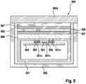
- the afore mentioned display foil 502 is glued to the outer surface of the inner housing 301 as well as to the inner surface of the outer housing 302 by means of an adhesive layer 506 and 507 on each side of the display foil 502.
- 520 in Fig. 5 to 9 refers to the black laser active layer and 521 refers to the white PET basis foil.
- a continuous adhesive layer 506, 507 is provided to fully cover the display foil 502, wherein such continuous adhesive layer may be made from a transparent adhesive to allow light going therethrough.
- the display foil 502 or at least a major portion thereof is in full contact with the corresponding inner or outer housing surface, thereby preventing the display foil 502 from corrugating or wrinkling or other undesired deformations.
- such full-size adhesive layer 506 and 507 can be provided on both, opposite sides of the display foil 502.
- only one side of the display foil 502 may be provided with such continuous full-size transparent adhesive layer, whereas the opposite side of the display foil 502 may be glued to the corresponding housing part by means of a frame-like adhesive layer having a window leaving open the central portion of the display foil 502.
- the advantage of such window is per one side to minimize or avoid the generation of bubbles because the glue layer is not properly fixed on the housing, per other side improve the light transmission.
- the bottom side of the display foil 502 may be glued to the inner housing 301 by means of a transparent adhesive layer 506 fully covering the display foil 502, whereas the top side of the display foil 502 can be glued to the outer housing 302 by means of a frame-like adhesive layer 507 having a central window 507w leaving open the central portion of the display foil 502.
- Said frame-like adhesive layer having a central window may be formed from a non-transparent, opaque adhesive.
- such frame-like adhesive layer having a central window also may be formed from an adhesive foam such as a PU foam or a PE foam so as to compensate for tolerances in the distance of the display foil 502 to the inner housing 301 or the outer housing 302.
- adhesive foam layer may have a multi-layered structure, wherein the foaming material may form a central or inner layer with sticky, adhesive layers provided on opposite sides and forming the surfaces of the adhesive foam layer, cf. Figures 8 and 9 .
- the adhesive foam layer may be provided on the top side of the display foil 502 to glue it to the outer housing 302, or may be provided on the bottom side of the display foil 502 to glue it to the inner housing 301.
- the other side of the display foil 502 of these two examples of Figures 8 and 9 may be glued to the other housing part by means of a continuous, substantially full-size transparent adhesive layer.
- the display foil 502 may include a laser-active layer allowing the display symbols 501a-n to be created in a laser treatment step, wherein lase light is applied to the display foil 502.
- such laser treatment can be made, after the display foil 502 has been glued to the inner housing 301.
- the outer housing 302, more particularly the outer housing display part 302d may be glued onto the top surface of the display foil 502.
- the laser treatment may be applied at the end of the shaver assembly process.
- the other shell elements 304 and 305 of the outer housing 302 may be assembled to form the outer housing 302.
- the preassembled electronic core of the shaver including the circuit board 504 with the light sources 503 supported thereon and optionally the motor 93 and the battery compartment may be inserted into the inner housing 301 before glueing the display foil 502 onto the outer surface of the inner housing 301, wherein the inner housing 301 may be completely closed and/or sealed before glueing the display foil 502 onto the inner housing 301.
- the display foil 502 may be glued onto the inner housing 301 and/or the laser markings thereof may be effected, before said electronic core including the circuit board 504 is inserted into the inner housing 301.
Landscapes
- Life Sciences & Earth Sciences (AREA)
- Forests & Forestry (AREA)
- Engineering & Computer Science (AREA)
- Mechanical Engineering (AREA)
- Dry Shavers And Clippers (AREA)
- Laser Beam Processing (AREA)
- Illuminated Signs And Luminous Advertising (AREA)
- Casings For Electric Apparatus (AREA)
- Devices For Indicating Variable Information By Combining Individual Elements (AREA)
Claims (17)
- Dispositif de soins personnels, en particulier dispositif d'épilation, plus particulièrement rasoir électrique, comprenant un logement (300) avec une tête fonctionnelle (3) attachée à celui-ci, ledit logement (300) incluant un logement interne (301) et un logement externe (302), et un affichage (500) incluant une source de lumière (503) logée dans le logement interne (301) pour émettre de la lumière à travers des portions transparentes (301d, 302d) dudit logement interne et externe (301, 302), ledit affichage (500) incluant en outre une feuille métallique d'affichage (502) ayant des portions de transparence différente et/ou de couleurs différentes formant des symboles d'affichage (501), ladite feuille métallique d'affichage (502) étant intercalée entre lesdites portions transparentes des logements interne et externe (301, 302), caractérisé en ce que ladite feuille métallique d'affichage (502) est collée à la fois aux logements interne et externe (301, 302) au moyen d'un adhésif (508) sur chacun des côtés opposés de la feuille métallique d'affichage (502).
- Dispositif de soins personnels selon la revendication précédente, dans lequel ledit adhésif (508) forme au moins une boucle d'étanchéification fermée entourant les symboles d'affichage (501) sur chacun desdits côtés opposés pour étanchéifier la feuille métallique d'affichage (502) contre les logements interne et externe (301, 302) pour empêcher du liquide ou de l'humidité d'être mis en contact avec la feuille métallique d'affichage (502) à l'intérieur de ladite boucle d'étanchéification adhésive.
- Dispositif de soins personnels selon l'une quelconque des revendications précédentes, dans lequel sur un côté de ladite feuille métallique d'affichage (502), ledit adhésif (508) forme une couche adhésive transparente (506, 507) couvrant au moins une portion majeure de la feuille métallique d'affichage (502) incluant les symboles d'affichage (501) de celle-ci, tandis que sur l'autre côté opposé de ladite feuille métallique d'affichage (502), l'adhésif (508) forme une couche adhésive (506, 507) ayant une fenêtre (506w, 507w) laissant ouverts les symboles d'affichage (501) et/ou une portion centrale de ladite feuille métallique d'affichage (502).
- Dispositif de soins personnels selon l'une quelconque des revendications précédentes, dans lequel l'adhésif (508) de part et d'autre de la feuille métallique d'affichage (502) est un adhésif transparent.
- Dispositif de soins personnels selon la revendication 3, dans lequel la couche adhésive (506, 507) ayant ladite fenêtre (506w, 507w) est faite à partir d'un adhésif non transparent.
- Dispositif de soins personnels selon l'une quelconque des revendications précédentes, dans lequel au moins un côté de ladite feuille métallique d'affichage (502) est collé au logement (300) au moyen d'une mousse adhésive.
- Dispositif de soins personnels selon la revendication précédente en combinaison avec la revendication 3, dans lequel la couche adhésive (506, 507) ayant la fenêtre (506w, 507w) inclut une couche de mousse adhésive et/ou une couche de mousse de polyuréthane adhésive et/ou une couche de mousse de polyéthylène adhésive et ou ayant fourni la fenêtre dans le côté de logement interne.
- Dispositif de soins personnels selon l'une quelconque des revendications précédentes, dans lequel le logement externe (302) est composé d'une pluralité de parties de logement, dans lequel une partie d'affichage de logement externe (302) à laquelle la feuille métallique d'affichage (502) est collée, forme un insert transparent essentiellement de type plaque reçu dans une portion de cadre de fenêtre d'une autre partie de logement (304) du logement externe (302).
- Dispositif de soins personnels selon la revendication précédente, dans lequel ladite autre partie de logement externe (304), avec une portion de bord de sa fenêtre, se chevauche avec une surface externe de ladite partie d'affichage de logement externe (302d) au niveau d'une portion de bord de celui-ci.
- Dispositif de soins personnels selon l'une quelconque des revendications précédentes, dans lequel le logement interne (301) est une partie de moule en plastique à plusieurs composants faite à partir d'un composant de matériau de plastique dur transparent formant l'au moins une partie d'affichage de logement interne transparent (301d) alignée avec la feuille métallique d'affichage (502) et une partie de matériau de plastique souple ou dur opaque (301o) entourant ladite partie d'affichage de logement interne (301d).
- Dispositif de soins personnels selon l'une quelconque des revendications précédentes, dans lequel le logement interne (301) inclut une structure de barrière d'ombrage de type grille constituée de matériau opaque (301o), ladite structure de barrière d'ombrage séparant une pluralité de portions de logement transparentes (301d) alignées avec les symboles d'affichage (501) de la feuille métallique d'affichage (502) les unes des autres, ladite structure de barrière d'ombrage empêchant de la lumière à être transmise à travers l'une de ladite pluralité de portions de logement transparentes (301d) vers l'un des symboles d'affichage (501) de s'étaler et se disperser vers l'un des autres symboles d'affichage (501).
- Dispositif de soins personnels selon l'une quelconque des revendications précédentes, dans lequel ladite au moins une source de lumière (503) est entourée par un tuyau de lumière de type manchon (509) s'étendant à partir de ladite source de lumière (503) vers la surface interne du logement interne (301), ledit tuyau de lumière (509) ayant un axe longitudinal essentiellement linéaire essentiellement parallèle à la direction d'émission principale de la source de lumière (503) et essentiellement perpendiculaire à la feuille métallique d'affichage (502).
- Dispositif de soins personnels selon la revendication précédente, dans lequel ledit tuyau de lumière (509) est fait à partir d'un matériau spongieux ou d'une éponge en caoutchouc et est mis en contact avec la surface interne du logement interne (301) ainsi qu'une surface d'une carte de circuit (504) supportant ladite au moins une source de lumière (503).
- Dispositif de soins personnels selon l'une des deux revendications précédentes, dans lequel une pluralité de sources de lumière (503) sont agencées dans un motif correspondant à un motif des symboles d'affichage (501), dans lequel une pluralité de tuyaux de lumière (509) est fournie pour restreindre la lumière émise par chacune de ladite pluralité de sources de lumière (503) vers l'un de ladite pluralité de symboles d'affichage (501), dans lequel ladite pluralité de tuyaux de lumière (509) est formée par une structure de barrière de type grille faite d'un matériau opaque.
- Procédé de fabrication d'un dispositif de soins personnels selon l'une quelconque des revendications précédentes, comprenant les étapes suivantes :- attacher de manière fixe une feuille métallique d'affichage (502) lisse au logement interne (301),- après avoir attaché ladite feuille métallique d'affichage (502) lisse, marquer ladite feuille métallique d'affichage (502) avec des symboles d'affichage (501) au moyen d'un traitement de marquage.
- Procédé selon la revendication 15, dans lequel ledit traitement de marquage inclut l'application d'un faisceau laser sur ladite feuille métallique d'affichage (502).
- Procédé selon la revendication 15 ou 16, dans lequel ledit traitement de marquage est appliqué après assemblage du logement de dispositif avec toutes les parties d'affichage montées sur celui-ci et/ou une activation de faisceau laser de la feuille métallique d'affichage est appliquée à travers à la fois le logement externe et interne.
Priority Applications (3)
| Application Number | Priority Date | Filing Date | Title |
|---|---|---|---|
| EP18164823.9A EP3546155B1 (fr) | 2018-03-29 | 2018-03-29 | Dispositif de soins personnels tel qu'un rasoir électrique |
| JP2019058955A JP6940545B2 (ja) | 2018-03-29 | 2019-03-26 | 電気シェーバ等のパーソナルケア装置 |
| CN201910240173.3A CN110315577B (zh) | 2018-03-29 | 2019-03-28 | 个人护理装置及其制造方法 |
Applications Claiming Priority (1)
| Application Number | Priority Date | Filing Date | Title |
|---|---|---|---|
| EP18164823.9A EP3546155B1 (fr) | 2018-03-29 | 2018-03-29 | Dispositif de soins personnels tel qu'un rasoir électrique |
Publications (2)
| Publication Number | Publication Date |
|---|---|
| EP3546155A1 EP3546155A1 (fr) | 2019-10-02 |
| EP3546155B1 true EP3546155B1 (fr) | 2022-07-20 |
Family
ID=61837617
Family Applications (1)
| Application Number | Title | Priority Date | Filing Date |
|---|---|---|---|
| EP18164823.9A Active EP3546155B1 (fr) | 2018-03-29 | 2018-03-29 | Dispositif de soins personnels tel qu'un rasoir électrique |
Country Status (3)
| Country | Link |
|---|---|
| EP (1) | EP3546155B1 (fr) |
| JP (1) | JP6940545B2 (fr) |
| CN (1) | CN110315577B (fr) |
Families Citing this family (1)
| Publication number | Priority date | Publication date | Assignee | Title |
|---|---|---|---|---|
| EP3821757B1 (fr) * | 2019-11-18 | 2024-04-17 | Braun GmbH | Dispositif de soins personnels |
Family Cites Families (15)
| Publication number | Priority date | Publication date | Assignee | Title |
|---|---|---|---|---|
| FR1158440A (fr) | 1956-10-23 | 1958-06-13 | Perfectionnements aux rasoirs électriques | |
| FR1391957A (fr) | 1964-01-30 | 1965-03-12 | Thomson Houston Comp Francaise | Perfectionnements aux rasoirs électriques |
| US3748371A (en) | 1972-05-18 | 1973-07-24 | Ericsson Telefon Ab L M | Insulated cable with wire for slitting a protective sheath |
| DE4244164C2 (de) | 1992-12-24 | 1995-09-07 | Braun Ag | Trockenrasierapparat mit einem schwenkbar gelagerten Langhaarschneider |
| JP2002528202A (ja) * | 1998-10-23 | 2002-09-03 | コーニンクレッカ フィリップス エレクトロニクス エヌ ヴィ | 合成樹脂パネルが設けられた合成樹脂壁部を備えるハウジングを有する装置 |
| AU2003209161A1 (en) * | 2002-01-08 | 2003-07-24 | American Design Group | Visual user interface for hair styling apparatus |
| WO2005051615A1 (fr) * | 2003-11-25 | 2005-06-09 | Koninklijke Philips Electronics N.V. | Appareil de rasage et procede de fabrication correspondant |
| CN2721342Y (zh) * | 2004-08-24 | 2005-08-31 | 易耀实业有限公司 | 具有防水防潮功能的电动剪发器 |
| DE102006010323A1 (de) | 2006-03-07 | 2007-09-13 | Braun Gmbh | Trockenrasierer mit schwenkbarem Scherkopf |
| DE102006030947A1 (de) | 2006-07-05 | 2008-01-10 | Braun Gmbh | Elektrischer Trockenrasierapparat |
| CN201338286Y (zh) * | 2008-12-16 | 2009-11-04 | 上海奔腾电工有限公司 | 电动剃须刀轻触开关防水及电量显示结构 |
| JP2011200451A (ja) * | 2010-03-25 | 2011-10-13 | Panasonic Electric Works Co Ltd | 電動歯ブラシ |
| JP2012179142A (ja) * | 2011-02-28 | 2012-09-20 | Panasonic Corp | 小型電気機器 |
| JP6298574B2 (ja) * | 2014-07-07 | 2018-03-20 | コーニンクレッカ フィリップス エヌ ヴェKoninklijke Philips N.V. | ヘアクリッピングデバイス |
| JP6222793B2 (ja) * | 2014-11-06 | 2017-11-01 | コーニンクレッカ フィリップス エヌ ヴェKoninklijke Philips N.V. | ヘアクリッピング装置 |
-
2018
- 2018-03-29 EP EP18164823.9A patent/EP3546155B1/fr active Active
-
2019
- 2019-03-26 JP JP2019058955A patent/JP6940545B2/ja active Active
- 2019-03-28 CN CN201910240173.3A patent/CN110315577B/zh active Active
Also Published As
| Publication number | Publication date |
|---|---|
| CN110315577A (zh) | 2019-10-11 |
| CN110315577B (zh) | 2021-09-03 |
| JP6940545B2 (ja) | 2021-09-29 |
| EP3546155A1 (fr) | 2019-10-02 |
| JP2019171066A (ja) | 2019-10-10 |
Similar Documents
| Publication | Publication Date | Title |
|---|---|---|
| US8434621B2 (en) | Wiper blade packing case | |
| EP3546154B1 (fr) | Rasoir électrique | |
| US11077568B2 (en) | Electric shaver | |
| US20110016721A1 (en) | Illuminated Button Assembly | |
| EP3546155B1 (fr) | Dispositif de soins personnels tel qu'un rasoir électrique | |
| EP2565084B1 (fr) | Rétroviseur de portière de véhicule | |
| AR011714A1 (es) | Conjunto de envasado y de aplicacion de un producto liquido | |
| BR9509326A (pt) | Cabo de barbeador | |
| JP4975802B2 (ja) | 車両用照明装置 | |
| GB2451212A (en) | Manual hair trimmer | |
| US20060275089A1 (en) | Power tool with gel grip including an integral backing | |
| KR20200002432U (ko) | 탈모치료기 | |
| JP3224382U (ja) | マイナスイオン電動歯ブラシ | |
| US20230373118A1 (en) | Personal care device and method of manufacturing such personal care device | |
| CN219846922U (zh) | 牙刷手柄和电动牙刷 | |
| WO2002097518A1 (fr) | Dispositif de nettoyage de lentilles de contact | |
| EP4006407B1 (fr) | Dispositif d'éclairage et/ou de signalisation automobile équipé d'un élément décoratif externe et procédé d'assemblage associé | |
| CN112008770B (zh) | 一种能整体浮动的电动剃须刀 | |
| CN209283449U (zh) | 按键防水结构及耳机 | |
| JP3213210U (ja) | 発光栓 | |
| JP3131033U (ja) | サイド投光型の超薄ライトガイドキーモジュール | |
| KR101836683B1 (ko) | 차량용 컵홀더 및 컵홀더용 텀블러 | |
| JP2005312598A (ja) | 電気カミソリ | |
| JP2001156337A (ja) | 小形電気機器用の導光体 | |
| JP3084028U (ja) | 自動車保護装置 |
Legal Events
| Date | Code | Title | Description |
|---|---|---|---|
| PUAI | Public reference made under article 153(3) epc to a published international application that has entered the european phase |
Free format text: ORIGINAL CODE: 0009012 |
|
| STAA | Information on the status of an ep patent application or granted ep patent |
Free format text: STATUS: THE APPLICATION HAS BEEN PUBLISHED |
|
| AK | Designated contracting states |
Kind code of ref document: A1 Designated state(s): AL AT BE BG CH CY CZ DE DK EE ES FI FR GB GR HR HU IE IS IT LI LT LU LV MC MK MT NL NO PL PT RO RS SE SI SK SM TR |
|
| AX | Request for extension of the european patent |
Extension state: BA ME |
|
| STAA | Information on the status of an ep patent application or granted ep patent |
Free format text: STATUS: REQUEST FOR EXAMINATION WAS MADE |
|
| 17P | Request for examination filed |
Effective date: 20200416 |
|
| RBV | Designated contracting states (corrected) |
Designated state(s): AL AT BE BG CH CY CZ DE DK EE ES FI FR GB GR HR HU IE IS IT LI LT LU LV MC MK MT NL NO PL PT RO RS SE SI SK SM TR |
|
| RIC1 | Information provided on ipc code assigned before grant |
Ipc: B26B 19/38 20060101AFI20211130BHEP |
|
| GRAP | Despatch of communication of intention to grant a patent |
Free format text: ORIGINAL CODE: EPIDOSNIGR1 |
|
| STAA | Information on the status of an ep patent application or granted ep patent |
Free format text: STATUS: GRANT OF PATENT IS INTENDED |
|
| INTG | Intention to grant announced |
Effective date: 20220224 |
|
| GRAS | Grant fee paid |
Free format text: ORIGINAL CODE: EPIDOSNIGR3 |
|
| GRAA | (expected) grant |
Free format text: ORIGINAL CODE: 0009210 |
|
| STAA | Information on the status of an ep patent application or granted ep patent |
Free format text: STATUS: THE PATENT HAS BEEN GRANTED |
|
| AK | Designated contracting states |
Kind code of ref document: B1 Designated state(s): AL AT BE BG CH CY CZ DE DK EE ES FI FR GB GR HR HU IE IS IT LI LT LU LV MC MK MT NL NO PL PT RO RS SE SI SK SM TR |
|
| REG | Reference to a national code |
Ref country code: CH Ref legal event code: EP |
|
| REG | Reference to a national code |
Ref country code: DE Ref legal event code: R096 Ref document number: 602018038038 Country of ref document: DE |
|
| REG | Reference to a national code |
Ref country code: AT Ref legal event code: REF Ref document number: 1505247 Country of ref document: AT Kind code of ref document: T Effective date: 20220815 |
|
| REG | Reference to a national code |
Ref country code: NL Ref legal event code: FP |
|
| REG | Reference to a national code |
Ref country code: IE Ref legal event code: FG4D |
|
| REG | Reference to a national code |
Ref country code: LT Ref legal event code: MG9D |
|
| PG25 | Lapsed in a contracting state [announced via postgrant information from national office to epo] |
Ref country code: SE Free format text: LAPSE BECAUSE OF FAILURE TO SUBMIT A TRANSLATION OF THE DESCRIPTION OR TO PAY THE FEE WITHIN THE PRESCRIBED TIME-LIMIT Effective date: 20220720 Ref country code: RS Free format text: LAPSE BECAUSE OF FAILURE TO SUBMIT A TRANSLATION OF THE DESCRIPTION OR TO PAY THE FEE WITHIN THE PRESCRIBED TIME-LIMIT Effective date: 20220720 Ref country code: PT Free format text: LAPSE BECAUSE OF FAILURE TO SUBMIT A TRANSLATION OF THE DESCRIPTION OR TO PAY THE FEE WITHIN THE PRESCRIBED TIME-LIMIT Effective date: 20221121 Ref country code: NO Free format text: LAPSE BECAUSE OF FAILURE TO SUBMIT A TRANSLATION OF THE DESCRIPTION OR TO PAY THE FEE WITHIN THE PRESCRIBED TIME-LIMIT Effective date: 20221020 Ref country code: LV Free format text: LAPSE BECAUSE OF FAILURE TO SUBMIT A TRANSLATION OF THE DESCRIPTION OR TO PAY THE FEE WITHIN THE PRESCRIBED TIME-LIMIT Effective date: 20220720 Ref country code: LT Free format text: LAPSE BECAUSE OF FAILURE TO SUBMIT A TRANSLATION OF THE DESCRIPTION OR TO PAY THE FEE WITHIN THE PRESCRIBED TIME-LIMIT Effective date: 20220720 Ref country code: FI Free format text: LAPSE BECAUSE OF FAILURE TO SUBMIT A TRANSLATION OF THE DESCRIPTION OR TO PAY THE FEE WITHIN THE PRESCRIBED TIME-LIMIT Effective date: 20220720 Ref country code: ES Free format text: LAPSE BECAUSE OF FAILURE TO SUBMIT A TRANSLATION OF THE DESCRIPTION OR TO PAY THE FEE WITHIN THE PRESCRIBED TIME-LIMIT Effective date: 20220720 |
|
| REG | Reference to a national code |
Ref country code: AT Ref legal event code: MK05 Ref document number: 1505247 Country of ref document: AT Kind code of ref document: T Effective date: 20220720 |
|
| PG25 | Lapsed in a contracting state [announced via postgrant information from national office to epo] |
Ref country code: PL Free format text: LAPSE BECAUSE OF FAILURE TO SUBMIT A TRANSLATION OF THE DESCRIPTION OR TO PAY THE FEE WITHIN THE PRESCRIBED TIME-LIMIT Effective date: 20220720 Ref country code: IS Free format text: LAPSE BECAUSE OF FAILURE TO SUBMIT A TRANSLATION OF THE DESCRIPTION OR TO PAY THE FEE WITHIN THE PRESCRIBED TIME-LIMIT Effective date: 20221120 Ref country code: HR Free format text: LAPSE BECAUSE OF FAILURE TO SUBMIT A TRANSLATION OF THE DESCRIPTION OR TO PAY THE FEE WITHIN THE PRESCRIBED TIME-LIMIT Effective date: 20220720 Ref country code: GR Free format text: LAPSE BECAUSE OF FAILURE TO SUBMIT A TRANSLATION OF THE DESCRIPTION OR TO PAY THE FEE WITHIN THE PRESCRIBED TIME-LIMIT Effective date: 20221021 |
|
| REG | Reference to a national code |
Ref country code: DE Ref legal event code: R097 Ref document number: 602018038038 Country of ref document: DE |
|
| PG25 | Lapsed in a contracting state [announced via postgrant information from national office to epo] |
Ref country code: SM Free format text: LAPSE BECAUSE OF FAILURE TO SUBMIT A TRANSLATION OF THE DESCRIPTION OR TO PAY THE FEE WITHIN THE PRESCRIBED TIME-LIMIT Effective date: 20220720 Ref country code: RO Free format text: LAPSE BECAUSE OF FAILURE TO SUBMIT A TRANSLATION OF THE DESCRIPTION OR TO PAY THE FEE WITHIN THE PRESCRIBED TIME-LIMIT Effective date: 20220720 Ref country code: DK Free format text: LAPSE BECAUSE OF FAILURE TO SUBMIT A TRANSLATION OF THE DESCRIPTION OR TO PAY THE FEE WITHIN THE PRESCRIBED TIME-LIMIT Effective date: 20220720 Ref country code: CZ Free format text: LAPSE BECAUSE OF FAILURE TO SUBMIT A TRANSLATION OF THE DESCRIPTION OR TO PAY THE FEE WITHIN THE PRESCRIBED TIME-LIMIT Effective date: 20220720 Ref country code: AT Free format text: LAPSE BECAUSE OF FAILURE TO SUBMIT A TRANSLATION OF THE DESCRIPTION OR TO PAY THE FEE WITHIN THE PRESCRIBED TIME-LIMIT Effective date: 20220720 |
|
| PGFP | Annual fee paid to national office [announced via postgrant information from national office to epo] |
Ref country code: FR Payment date: 20230208 Year of fee payment: 6 |
|
| PLBE | No opposition filed within time limit |
Free format text: ORIGINAL CODE: 0009261 |
|
| STAA | Information on the status of an ep patent application or granted ep patent |
Free format text: STATUS: NO OPPOSITION FILED WITHIN TIME LIMIT |
|
| PG25 | Lapsed in a contracting state [announced via postgrant information from national office to epo] |
Ref country code: SK Free format text: LAPSE BECAUSE OF FAILURE TO SUBMIT A TRANSLATION OF THE DESCRIPTION OR TO PAY THE FEE WITHIN THE PRESCRIBED TIME-LIMIT Effective date: 20220720 Ref country code: EE Free format text: LAPSE BECAUSE OF FAILURE TO SUBMIT A TRANSLATION OF THE DESCRIPTION OR TO PAY THE FEE WITHIN THE PRESCRIBED TIME-LIMIT Effective date: 20220720 |
|
| 26N | No opposition filed |
Effective date: 20230421 |
|
| PG25 | Lapsed in a contracting state [announced via postgrant information from national office to epo] |
Ref country code: AL Free format text: LAPSE BECAUSE OF FAILURE TO SUBMIT A TRANSLATION OF THE DESCRIPTION OR TO PAY THE FEE WITHIN THE PRESCRIBED TIME-LIMIT Effective date: 20220720 |
|
| PG25 | Lapsed in a contracting state [announced via postgrant information from national office to epo] |
Ref country code: SI Free format text: LAPSE BECAUSE OF FAILURE TO SUBMIT A TRANSLATION OF THE DESCRIPTION OR TO PAY THE FEE WITHIN THE PRESCRIBED TIME-LIMIT Effective date: 20220720 |
|
| PG25 | Lapsed in a contracting state [announced via postgrant information from national office to epo] |
Ref country code: MC Free format text: LAPSE BECAUSE OF FAILURE TO SUBMIT A TRANSLATION OF THE DESCRIPTION OR TO PAY THE FEE WITHIN THE PRESCRIBED TIME-LIMIT Effective date: 20220720 |
|
| REG | Reference to a national code |
Ref country code: CH Ref legal event code: PL |
|
| GBPC | Gb: european patent ceased through non-payment of renewal fee |
Effective date: 20230329 |
|
| REG | Reference to a national code |
Ref country code: BE Ref legal event code: MM Effective date: 20230331 |
|
| PG25 | Lapsed in a contracting state [announced via postgrant information from national office to epo] |
Ref country code: LU Free format text: LAPSE BECAUSE OF NON-PAYMENT OF DUE FEES Effective date: 20230329 |
|
| REG | Reference to a national code |
Ref country code: IE Ref legal event code: MM4A |
|
| PG25 | Lapsed in a contracting state [announced via postgrant information from national office to epo] |
Ref country code: GB Free format text: LAPSE BECAUSE OF NON-PAYMENT OF DUE FEES Effective date: 20230329 |
|
| PG25 | Lapsed in a contracting state [announced via postgrant information from national office to epo] |
Ref country code: LI Free format text: LAPSE BECAUSE OF NON-PAYMENT OF DUE FEES Effective date: 20230331 Ref country code: IE Free format text: LAPSE BECAUSE OF NON-PAYMENT OF DUE FEES Effective date: 20230329 Ref country code: GB Free format text: LAPSE BECAUSE OF NON-PAYMENT OF DUE FEES Effective date: 20230329 Ref country code: CH Free format text: LAPSE BECAUSE OF NON-PAYMENT OF DUE FEES Effective date: 20230331 |
|
| PG25 | Lapsed in a contracting state [announced via postgrant information from national office to epo] |
Ref country code: BE Free format text: LAPSE BECAUSE OF NON-PAYMENT OF DUE FEES Effective date: 20230331 |
|
| PGFP | Annual fee paid to national office [announced via postgrant information from national office to epo] |
Ref country code: NL Payment date: 20240214 Year of fee payment: 7 |
|
| PGFP | Annual fee paid to national office [announced via postgrant information from national office to epo] |
Ref country code: DE Payment date: 20240130 Year of fee payment: 7 |