EP3545860A2 - Chirurgische klammervorrichtungen mit asymmetrischen verschlusselementen - Google Patents
Chirurgische klammervorrichtungen mit asymmetrischen verschlusselementen Download PDFInfo
- Publication number
- EP3545860A2 EP3545860A2 EP19165949.9A EP19165949A EP3545860A2 EP 3545860 A2 EP3545860 A2 EP 3545860A2 EP 19165949 A EP19165949 A EP 19165949A EP 3545860 A2 EP3545860 A2 EP 3545860A2
- Authority
- EP
- European Patent Office
- Prior art keywords
- closure
- patent application
- jaw
- anvil
- end effector
- Prior art date
- Legal status (The legal status is an assumption and is not a legal conclusion. Google has not performed a legal analysis and makes no representation as to the accuracy of the status listed.)
- Granted
Links
Images


Classifications
-
- A—HUMAN NECESSITIES
- A61—MEDICAL OR VETERINARY SCIENCE; HYGIENE
- A61B—DIAGNOSIS; SURGERY; IDENTIFICATION
- A61B17/00—Surgical instruments, devices or methods
- A61B17/068—Surgical staplers, e.g. containing multiple staples or clamps
- A61B17/072—Surgical staplers, e.g. containing multiple staples or clamps for applying a row of staples in a single action, e.g. the staples being applied simultaneously
- A61B17/07207—Surgical staplers, e.g. containing multiple staples or clamps for applying a row of staples in a single action, e.g. the staples being applied simultaneously the staples being applied sequentially
-
- A—HUMAN NECESSITIES
- A61—MEDICAL OR VETERINARY SCIENCE; HYGIENE
- A61B—DIAGNOSIS; SURGERY; IDENTIFICATION
- A61B17/00—Surgical instruments, devices or methods
- A61B17/28—Surgical forceps
- A61B17/29—Forceps for use in minimally invasive surgery
-
- A—HUMAN NECESSITIES
- A61—MEDICAL OR VETERINARY SCIENCE; HYGIENE
- A61B—DIAGNOSIS; SURGERY; IDENTIFICATION
- A61B17/00—Surgical instruments, devices or methods
- A61B2017/00367—Details of actuation of instruments, e.g. relations between pushing buttons, or the like, and activation of the tool, working tip, or the like
- A61B2017/00398—Details of actuation of instruments, e.g. relations between pushing buttons, or the like, and activation of the tool, working tip, or the like using powered actuators, e.g. stepper motors, solenoids
-
- A—HUMAN NECESSITIES
- A61—MEDICAL OR VETERINARY SCIENCE; HYGIENE
- A61B—DIAGNOSIS; SURGERY; IDENTIFICATION
- A61B17/00—Surgical instruments, devices or methods
- A61B2017/0046—Surgical instruments, devices or methods with a releasable handle; with handle and operating part separable
-
- A—HUMAN NECESSITIES
- A61—MEDICAL OR VETERINARY SCIENCE; HYGIENE
- A61B—DIAGNOSIS; SURGERY; IDENTIFICATION
- A61B17/00—Surgical instruments, devices or methods
- A61B17/068—Surgical staplers, e.g. containing multiple staples or clamps
- A61B17/072—Surgical staplers, e.g. containing multiple staples or clamps for applying a row of staples in a single action, e.g. the staples being applied simultaneously
- A61B2017/07214—Stapler heads
- A61B2017/07257—Stapler heads characterised by its anvil
-
- A—HUMAN NECESSITIES
- A61—MEDICAL OR VETERINARY SCIENCE; HYGIENE
- A61B—DIAGNOSIS; SURGERY; IDENTIFICATION
- A61B17/00—Surgical instruments, devices or methods
- A61B17/068—Surgical staplers, e.g. containing multiple staples or clamps
- A61B17/072—Surgical staplers, e.g. containing multiple staples or clamps for applying a row of staples in a single action, e.g. the staples being applied simultaneously
- A61B2017/07214—Stapler heads
- A61B2017/07285—Stapler heads characterised by its cutter
-
- A—HUMAN NECESSITIES
- A61—MEDICAL OR VETERINARY SCIENCE; HYGIENE
- A61B—DIAGNOSIS; SURGERY; IDENTIFICATION
- A61B17/00—Surgical instruments, devices or methods
- A61B17/28—Surgical forceps
- A61B17/29—Forceps for use in minimally invasive surgery
- A61B2017/2901—Details of shaft
- A61B2017/2902—Details of shaft characterized by features of the actuating rod
- A61B2017/2903—Details of shaft characterized by features of the actuating rod transferring rotary motion
-
- A—HUMAN NECESSITIES
- A61—MEDICAL OR VETERINARY SCIENCE; HYGIENE
- A61B—DIAGNOSIS; SURGERY; IDENTIFICATION
- A61B17/00—Surgical instruments, devices or methods
- A61B17/28—Surgical forceps
- A61B17/29—Forceps for use in minimally invasive surgery
- A61B2017/2926—Details of heads or jaws
- A61B2017/2927—Details of heads or jaws the angular position of the head being adjustable with respect to the shaft
-
- A—HUMAN NECESSITIES
- A61—MEDICAL OR VETERINARY SCIENCE; HYGIENE
- A61B—DIAGNOSIS; SURGERY; IDENTIFICATION
- A61B17/00—Surgical instruments, devices or methods
- A61B17/28—Surgical forceps
- A61B17/29—Forceps for use in minimally invasive surgery
- A61B2017/2926—Details of heads or jaws
- A61B2017/2932—Transmission of forces to jaw members
- A61B2017/2933—Transmission of forces to jaw members camming or guiding means
-
- A—HUMAN NECESSITIES
- A61—MEDICAL OR VETERINARY SCIENCE; HYGIENE
- A61B—DIAGNOSIS; SURGERY; IDENTIFICATION
- A61B17/00—Surgical instruments, devices or methods
- A61B17/28—Surgical forceps
- A61B17/29—Forceps for use in minimally invasive surgery
- A61B2017/2926—Details of heads or jaws
- A61B2017/2932—Transmission of forces to jaw members
- A61B2017/2939—Details of linkages or pivot points
- A61B2017/2941—Toggle linkages
-
- A—HUMAN NECESSITIES
- A61—MEDICAL OR VETERINARY SCIENCE; HYGIENE
- A61B—DIAGNOSIS; SURGERY; IDENTIFICATION
- A61B17/00—Surgical instruments, devices or methods
- A61B17/28—Surgical forceps
- A61B17/29—Forceps for use in minimally invasive surgery
- A61B2017/2926—Details of heads or jaws
- A61B2017/2932—Transmission of forces to jaw members
- A61B2017/2943—Toothed members, e.g. rack and pinion
-
- A—HUMAN NECESSITIES
- A61—MEDICAL OR VETERINARY SCIENCE; HYGIENE
- A61B—DIAGNOSIS; SURGERY; IDENTIFICATION
- A61B17/00—Surgical instruments, devices or methods
- A61B17/28—Surgical forceps
- A61B17/29—Forceps for use in minimally invasive surgery
- A61B2017/2947—Pivots
Definitions
- the present invention relates to surgical instruments and, in various arrangements, to surgical stapling and cutting instruments and staple cartridges for use therewith that are designed to staple and cut tissue.
- proximal and distal are used herein with reference to a clinician manipulating the handle portion of the surgical instrument.
- proximal refers to the portion closest to the clinician and the term “distal” refers to the portion located away from the clinician.
- distal refers to the portion located away from the clinician.
- spatial terms such as “vertical”, “horizontal”, “up”, and “down” may be used herein with respect to the drawings.
- surgical instruments are used in many orientations and positions, and these terms are not intended to be limiting and/or absolute.
- Various exemplary devices and methods are provided for performing laparoscopic and minimally invasive surgical procedures.
- the various methods and devices disclosed herein can be used in numerous surgical procedures and applications including, for example, in connection with open surgical procedures.
- the various instruments disclosed herein can be inserted into a body in any way, such as through a natural orifice, through an incision or puncture hole formed in tissue, etc.
- the working portions or end effector portions of the instruments can be inserted directly into a patient's body or can be inserted through an access device that has a working channel through which the end effector and elongate shaft of a surgical instrument can be advanced.
- a surgical stapling system can comprise a shaft and an end effector extending from the shaft.
- the end effector comprises a first jaw and a second jaw.
- the first jaw comprises a staple cartridge.
- the staple cartridge is insertable into and removable from the first jaw; however, other embodiments are envisioned in which a staple cartridge is not removable from, or at least readily replaceable from, the first jaw.
- the second jaw comprises an anvil configured to deform staples ejected from the staple cartridge.
- the second jaw is pivotable relative to the first jaw about a closure axis; however, other embodiments are envisioned in which the first jaw is pivotable relative to the second jaw.
- the surgical stapling system further comprises an articulation joint configured to permit the end effector to be rotated, or articulated, relative to the shaft.
- the end effector is rotatable about an articulation axis extending through the articulation joint. Other embodiments are envisioned which do not include an articulation joint.
- the staple cartridge comprises a cartridge body.
- the cartridge body includes a proximal end, a distal end, and a deck extending between the proximal end and the distal end.
- the staple cartridge is positioned on a first side of the tissue to be stapled and the anvil is positioned on a second side of the tissue.
- the anvil is moved toward the staple cartridge to compress and clamp the tissue against the deck.
- staples removably stored in the cartridge body can be deployed into the tissue.
- the cartridge body includes staple cavities defined therein wherein staples are removably stored in the staple cavities.
- the staple cavities are arranged in six longitudinal rows. Three rows of staple cavities are positioned on a first side of a longitudinal slot and three rows of staple cavities are positioned on a second side of the longitudinal slot. Other arrangements of staple cavities and staples may be possible.
- the staples are supported by staple drivers in the cartridge body.
- the drivers are movable between a first, or unfired position, and a second, or fired, position to eject the staples from the staple cavities.
- the drivers are retained in the cartridge body by a retainer which extends around the bottom of the cartridge body and includes resilient members configured to grip the cartridge body and hold the retainer to the cartridge body.
- the drivers are movable between their unfired positions and their fired positions by a sled.
- the sled is movable between a proximal position adjacent the proximal end and a distal position adjacent the distal end.
- the sled comprises a plurality of ramped surfaces configured to slide under the drivers and lift the drivers, and the staples supported thereon, toward the anvil.
- the sled is moved distally by a firing member.
- the firing member is configured to contact the sled and push the sled toward the distal end.
- the longitudinal slot defined in the cartridge body is configured to receive the firing member.
- the anvil also includes a slot configured to receive the firing member.
- the firing member further comprises a first cam which engages the first jaw and a second cam which engages the second jaw. As the firing member is advanced distally, the first cam and the second cam can control the distance, or tissue gap, between the deck of the staple cartridge and the anvil.
- the firing member also comprises a knife configured to incise the tissue captured intermediate the staple cartridge and the anvil. It is desirable for the knife to be positioned at least partially proximal to the ramped surfaces such that the staples are ejected ahead of the knife.
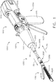
- FIG. 1 illustrates the surgical instrument 1010 that includes an interchangeable shaft assembly 1200 operably coupled to a housing 1012.
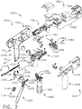
- FIG. 2 illustrates the interchangeable shaft assembly 1200 detached from the housing 1012 or handle 1014.
- the handle 1014 may comprise a pair of interconnectable handle housing segments 1016 and 1018 that may be interconnected by screws, snap features, adhesive, etc.
- the handle housing segments 1016, 1018 cooperate to form a pistol grip portion 1019.
- FIGS. 1 and 3 depict a motor-driven surgical cutting and fastening instrument 1010 that may or may not be reused.
- the instrument 1010 includes a previous housing 1012 that comprises a handle 1014 that is configured to be grasped, manipulated and actuated by the clinician.
- the housing 1012 is configured for operable attachment to an interchangeable shaft assembly 1200 that has a surgical end effector 1300 operably coupled thereto that is configured to perform one or more surgical tasks or procedures.
- an interchangeable shaft assembly 1200 that has a surgical end effector 1300 operably coupled thereto that is configured to perform one or more surgical tasks or procedures.
- housing may also encompass a housing or similar portion of a robotic system that houses or otherwise operably supports at least one drive system that is configured to generate and apply at least one control motion which could be used to actuate the interchangeable shaft assemblies disclosed herein and their respective equivalents.
- various components may be “housed” or contained in the housing or various components may be “associated with” a housing. In such instances, the components may not be contained within the housing or supported directly by the housing.
- the term “frame” may refer to a portion of a handheld surgical instrument.
- the term “frame” may also represent a portion of a robotically controlled surgical instrument and/or a portion of the robotic system that may be used to operably control a surgical instrument.
- interchangeable shaft assemblies disclosed herein may be employed with various robotic systems, instruments, components and methods disclosed in U.S. Patent No. 9,072,535 , entitled SURGICAL STAPLING INSTRUMENTS WITH ROTATABLE STAPLE DEPLOYMENT ARRANGEMENTS, that is incorporated by reference herein in its entirety.
- the previous housing 1012 depicted in FIG. 1 is shown in connection with an interchangeable shaft assembly 1200 ( FIGS. 2 , 4 and 5 ) that includes an end effector 1300 that comprises a surgical cutting and fastening device that is configured to operably support a surgical staple cartridge 4000 therein.
- the housing 1012 may be configured for use in connection with interchangeable shaft assemblies that include end effectors that are adapted to support different sizes and types of staple cartridges, have different shaft lengths, sizes, and types, etc.
- the housing 1012 may also be effectively employed with a variety of other interchangeable shaft assemblies including those assemblies that are configured to apply other motions and forms of energy such as, for example, radio frequency (RF) energy, ultrasonic energy and/or motion to end effector arrangements adapted for use in connection with various surgical applications and procedures.
- RF radio frequency
- the end effectors, shaft assemblies, handles, surgical instruments, and/or surgical instrument systems can utilize any suitable fastener that can be gripped and manipulated by the clinician.
- the handle 1014 operably supports a plurality of drive systems therein that are configured to generate and apply various control motions to corresponding portions of the interchangeable shaft assembly that is operably attached thereto.
- the handle 1014 may further include a frame 1020 that operably supports a plurality of drive systems.
- the frame 1020 can operably support a "first" or closure drive system, generally designated as 1030, which may be employed to apply closing and opening motions to the interchangeable shaft assembly 1200 that is operably attached or coupled thereto.
- the closure drive system 1030 may include an actuator in the form of a closure trigger 1032 that is pivotally supported by the frame 1020. More specifically, as illustrated in FIG. 3 , the closure trigger 1032 is pivotally coupled to the handle 1014 by a pin 1033.
- the closure drive system 1030 further includes a closure linkage assembly 1034 that is pivotally coupled to the closure trigger 1032.
- the closure linkage assembly 1034 may include a first closure link 1036 and a second closure link 1038 that are pivotally coupled to the closure trigger 1032 by a pin 1035.
- the second closure link 1038 may also be referred to herein as an "attachment member” and include a transverse attachment pin 1037.
- the first closure link 1036 may have a locking wall or end 1039 thereon that is configured to cooperate with a closure release assembly 1060 that is pivotally coupled to the frame 1020.
- the closure release assembly 1060 may comprise a release button assembly 1062 that has a distally protruding locking pawl 1064 formed thereon.
- the release button assembly 1062 may be pivoted in a counterclockwise direction by a release spring (not shown).
- the closure release assembly 1060 serves to lock the closure trigger 1032 in the fully actuated position.
- the clinician simply pivots the closure release button assembly 1062 such that the locking pawl 1064 is moved out of engagement with the locking wall 1039 on the first closure link 1036.
- the closure trigger 1032 may pivot back to the unactuated position.
- Other closure trigger locking and release arrangements may also be employed.
- An arm 1061 may extend from the closure release button 1062.
- a magnetic element 1063 such as a permanent magnet, for example, may be mounted to the arm 1061.
- the circuit board 1100 can include at least one sensor that is configured to detect the movement of the magnetic element 1063.
- a "Hall Effect" sensor (not shown) can be mounted to the bottom surface of the circuit board 1100.
- the Hall Effect sensor can be configured to detect changes in a magnetic field surrounding the Hall Effect sensor caused by the movement of the magnetic element 1063.
- the Hall Effect sensor can be in signal communication with a microcontroller, for example, which can determine whether the closure release button 1062 is in its first position, which is associated with the unactuated position of the closure trigger 1032 and the open configuration of the end effector, its second position, which is associated with the actuated position of the closure trigger 1032 and the closed configuration of the end effector, and/or any position between the first position and the second position.
- a microcontroller for example, which can determine whether the closure release button 1062 is in its first position, which is associated with the unactuated position of the closure trigger 1032 and the open configuration of the end effector, its second position, which is associated with the actuated position of the closure trigger 1032 and the closed configuration of the end effector, and/or any position between the first position and the second position.
- the handle 1014 and the frame 1020 may operably support another drive system referred to herein as a firing drive system 1080 that is configured to apply firing motions to corresponding portions of the interchangeable shaft assembly attached thereto.
- the firing drive system 1080 may also be referred to herein as a "second drive system”.
- the firing drive system 1080 may employ an electric motor 1082 that is located in the pistol grip portion 1019 of the handle 1014.
- the motor 1082 may be a DC brushed driving motor having a maximum rotation of, approximately, 25,000 RPM, for example.
- the motor may include a brushless motor, a cordless motor, a synchronous motor, a stepper motor, or any other suitable electric motor.
- the motor 1082 may be powered by a power source 1090 that in one form may comprise a removable power pack 1092.
- the power pack 1092 may comprise a proximal housing portion 1094 that is configured for attachment to a distal housing portion 1096.
- the proximal housing portion 1094 and the distal housing portion 1096 are configured to operably support a plurality of batteries 1098 therein.
- Batteries 1098 may each comprise, for example, a Lithium Ion ("LI”) or other suitable battery.
- the distal housing portion 1096 is configured for removable operable attachment to the circuit board 1100 which is also operably coupled to the motor 1082.
- a number of batteries 1098 may be connected in series may be used as the power source for the surgical instrument 1010.
- the power source 1090 may be replaceable and/or rechargeable.
- the electric motor 1082 can include a rotatable shaft (not shown) that operably interfaces with a gear reducer assembly 1084 that is mounted in meshing engagement with a with a set, or rack, of drive teeth 1122 on a longitudinally-movable drive member 1120.
- a voltage polarity provided by the power source 1090 can operate the electric motor 1082 in a clockwise direction wherein the voltage polarity applied to the electric motor by the battery can be reversed in order to operate the electric motor 1082 in a counter-clockwise direction.
- the drive member 1120 will be axially driven in the distal direction "DD".
- the handle 1014 can include a switch which can be configured to reverse the polarity applied to the electric motor 1082 by the power source 1090. As with the other forms described herein, the handle 1014 can also include a sensor that is configured to detect the position of the drive member 1120 and/or the direction in which the drive member 1120 is being moved.
- Actuation of the motor 1082 can be controlled by a firing trigger 1130 that is pivotally supported on the handle 1014.
- the firing trigger 1130 may be pivoted between an unactuated position and an actuated position.
- the firing trigger 1130 may be biased into the unactuated position by a spring 1132 or other biasing arrangement such that when the clinician releases the firing trigger 1130, it may be pivoted or otherwise returned to the unactuated position by the spring 1132 or biasing arrangement.
- the firing trigger 1130 can be positioned "outboard" of the closure trigger 1032 as was discussed above.
- a firing trigger safety button 1134 may be pivotally mounted to the closure trigger 1032 by the pin 1035.
- the safety button 1134 may be positioned between the firing trigger 1130 and the closure trigger 1032 and have a pivot arm 1136 protruding therefrom.
- the safety button 1134 When the closure trigger 1032 is in the unactuated position, the safety button 1134 is contained in the handle 1014 where the clinician cannot readily access it and move it between a safety position preventing actuation of the firing trigger 1130 and a firing position wherein the firing trigger 1130 may be fired. As the clinician depresses the closure trigger 1032, the safety button 1134 and the firing trigger 1130 pivot down wherein they can then be manipulated by the clinician.
- the longitudinally movable drive member 1120 has a rack of teeth 1122 formed thereon for meshing engagement with a corresponding drive gear 1086 of the gear reducer assembly 1084.
- At least one form also includes a manually-actuatable "bailout” assembly 1140 that is configured to enable the clinician to manually retract the longitudinally movable drive member 1120 should the motor 1082 become disabled.
- the bailout assembly 1140 may include a lever or bailout handle assembly 1142 that is configured to be manually pivoted into ratcheting engagement with teeth 1124 also provided in the drive member 1120.
- the clinician can manually retract the drive member 1120 by using the bailout handle assembly 1142 to ratchet the drive member 1120 in the proximal direction "PD".
- Patent No. 8,608,045 entitled POWERED SURGICAL CUTTING AND STAPLING APPARATUS WITH MANUALLY RETRACTABLE FIRING SYSTEM, discloses bailout arrangements and other components, arrangements and systems that may also be employed with the various instruments disclosed herein.
- U.S. Patent No. 8,608,045 is hereby incorporated by reference herein in its entirety.
- the interchangeable shaft assembly 1200 includes a surgical end effector 1300 that comprises an elongate channel 1310 that is configured to operably support a staple cartridge 4000 therein.
- the end effector 1300 may further include an anvil 2000 that is pivotally supported relative to the elongate channel 1310.
- the interchangeable shaft assembly 1200 may further include an articulation joint 3020 and an articulation lock 2140 which can be configured to releasably hold the end effector 1300 in a desired position relative to a shaft axis SA. Examples of various features of at least one form of the end effector 1300, the articulation joint 3020 and articulation locks may be found in U.S. Patent Application Serial No.
- the interchangeable shaft assembly 1200 can further include a proximal housing or nozzle 1201 comprised of nozzle portions 1202 and 1203.
- the interchangeable shaft assembly 1200 can further include a closure system or closure member assembly 3000 which can be utilized to close and/or open the anvil 2000 of the end effector 1300.
- the shaft assembly 1200 can include a spine 1210 that is configured to, one, slidably support a firing member therein and, two, slidably support the closure member assembly 3000 which extends around the spine 1210.
- a distal end 1212 of spine 1210 terminates in an upper lug mount feature 1270 and in a lower lug mount feature 1280.
- the upper lug mount feature 1270 is formed with a lug slot 1272 therein that is adapted to mountingly support an upper mounting link 1274 therein.
- the lower lug mount feature 1280 is formed with a lug slot 1282 therein that is adapted to mountingly support a lower mounting link 1284 therein.
- the upper mounting link 1274 includes a pivot socket 1276 therein that is adapted to rotatably receive therein a pivot pin 1292 that is formed on a channel cap or anvil retainer 1290 that is attached to a proximal end portion 1312 of the elongate channel 1310.
- the lower mounting link 1284 includes lower pivot pin 1286 that adapted to be received within a pivot hole 1314 formed in the proximal end portion 1312 of the elongate channel 1310. See FIG. 5 .
- the lower pivot pin 1286 is vertically aligned with the pivot socket 1276 to define an articulation axis AA about which the surgical end effector 1300 may articulate relative to the shaft axis SA. See FIG. 2 .
- the surgical end effector 1300 is selectively articulatable about the articulation axis AA by an articulation system 2100.
- the articulation system 2100 includes proximal articulation driver 2102 that is pivotally coupled to an articulation link 2120.
- an offset attachment lug 2114 is formed on a distal end 2110 of the proximal articulation driver 2102.
- a pivot hole 2116 is formed in the offset attachment lug 2114 and is configured to pivotally receive therein a proximal link pin 2124 formed on the proximal end 2122 of the articulation link 2120.
- a distal end 2126 of the articulation link 2120 includes a pivot hole 2128 that is configured to pivotally receive therein a channel pin 1317 formed on the proximal end portion 1312 of the elongate channel 1310.
- proximal articulation driver 2102 can be held in position by an articulation lock 2140 when the proximal articulation driver 2102 is not being moved in the proximal or distal directions. Additional details regarding an example of an articulation lock 2140 may be found in U.S. Patent Application Serial No. 15/635,631 , now U.S. Patent Application Publication No. 2019/0000464 , as well as in other references incorporated by reference herein.
- the spine 1210 can comprise a proximal end 1211 which is rotatably supported in a chassis 1240.
- the proximal end 1211 of the spine 1210 has a thread 1214 formed thereon for threaded attachment to a spine bearing 1216 configured to be supported within the chassis 1240. See FIG. 4 .
- Such an arrangement facilitates rotatable attachment of the spine 1210 to the chassis 1240 such that the spine 1210 may be selectively rotated about a shaft axis SA relative to the chassis 1240.
- the interchangeable shaft assembly 1200 includes a closure shuttle 1250 that is slidably supported within the chassis 1240 such that it may be axially moved relative thereto.
- the closure shuttle 1250 includes a pair of proximally-protruding hooks 1252 that are configured for attachment to the attachment pin 1037 ( FIG. 3 ) that is attached to the second closure link 1038 as will be discussed in further detail below.
- the closure member assembly 3000 comprises a proximal closure member segment 3010 that has a proximal end 3012 that is coupled to the closure shuttle 1250 for relative rotation thereto.
- a U shaped connector 1263 is inserted into an annular slot 3014 in the proximal end 3012 of the proximal closure member segment 3010 and is retained within vertical slots 1253 in the closure shuttle 1250.
- Such an arrangement serves to attach the proximal closure member segment 3010 to the closure shuttle 1250 for axial travel therewith while enabling the proximal closure member segment 3010 to rotate relative to the closure shuttle 1250 about the shaft axis SA.
- a closure spring 1268 is journaled on the proximal closure member segment 3010 and serves to bias the proximal closure member segment 3010 in the proximal direction "PD" which can serve to pivot the closure trigger 1032 into the unactuated position when the shaft assembly is operably coupled to the handle 1014.
- the interchangeable shaft assembly 1200 may further include an articulation joint 3020.
- Other interchangeable shaft assemblies may not be capable of articulation.
- a distal closure member or distal closure tube segment 3030 is coupled to the distal end of the proximal closure member segment 3010.
- the articulation joint 3020 includes a double pivot closure sleeve assembly 3022.
- the double pivot closure sleeve assembly 3022 includes an end effector closure tube 3050 having upper and lower distally projecting tangs 3052, 3054.
- An upper double pivot link 3056 includes upwardly projecting distal and proximal pivot pins that engage respectively an upper distal pin hole in the upper proximally projecting tang 3052 and an upper proximal pin hole in an upper distally projecting tang 3032 on the distal closure tube segment 3030.
- a lower double pivot link 3058 includes upwardly projecting distal and proximal pivot pins that engage respectively a lower distal pin hole in the lower proximally projecting tang 3054 and a lower proximal pin hole in the lower distally projecting tang 3034. See FIGS. 4 and 5 .
- the closure member assembly 3000 is translated distally (direction "DD") to close the anvil 2000, for example, in response to the actuation of the closure trigger 1032.
- the anvil 2000 is opened by proximally translating the closure member assembly 3000 which causes the end effector closure sleeve to interact with the anvil 2000 and pivot it to an open position.
- the interchangeable shaft assembly 1200 further includes a firing member 1900 that is supported for axial travel within the spine 1210.
- the firing member 1900 includes an intermediate firing shaft portion 1222 that is configured for attachment to a distal cutting portion or knife bar 1910.
- the intermediate firing shaft portion 1222 may include a longitudinal slot 1223 in the distal end thereof which can be configured to receive a tab 1912 on the proximal end of the distal knife bar 1910.
- the longitudinal slot 1223 and the proximal end tab 1912 can be sized and configured to permit relative movement therebetween and can comprise a slip joint 1914.
- the slip joint 1914 can permit the intermediate firing shaft portion 1222 of the firing member 1900 to be moved to articulate the end effector 1300 without moving, or at least substantially moving, the knife bar 1910.
- the intermediate firing shaft portion 1222 can be advanced distally until a proximal sidewall of the longitudinal slot 1223 comes into contact with the tab 1912 in order to advance the knife bar 1910 and fire the staple cartridge 4000 positioned within the channel 1310.
- the knife bar 1910 includes a knife portion 1920 that includes a blade or tissue cutting edge 1922 and includes an upper anvil engagement tab 1924 and lower channel engagement tabs 1926.
- Various firing member configurations and operations are disclosed in various other references incorporated herein by reference.
- the shaft assembly 1200 further includes a switch drum 1500 that is rotatably received on proximal closure member segment 3010.
- the switch drum 1500 comprises a hollow shaft segment 1502 that has a shaft boss formed thereon for receive an outwardly protruding actuation pin therein.
- the actuation pin extends through a longitudinal slot provided in the lock sleeve to facilitate axial movement of the lock sleeve when it is engaged with the articulation driver.
- a rotary torsion spring 1420 is configured to engage the boss on the switch drum 1500 and a portion of the nozzle housing 1203 to apply a biasing force to the switch drum 1500.
- the switch drum 1500 can further comprise at least partially circumferential openings 1506 defined therein which can be configured to receive circumferential mounts extending from the nozzle portions 1202, 1203 and permit relative rotation, but not translation, between the switch drum 1500 and the nozzle 1201.
- the mounts also extend through openings 3011 in the proximal closure member segment 3010 to be seated in recesses 1219 in the spine 1210. Rotation of the switch drum 1500 about the shaft axis SA will ultimately result in the rotation of the actuation pin and the lock sleeve between its engaged and disengaged positions.
- the rotation of the switch drum 1500 may be linked to the axial advancement of the closure tube or closure member.
- actuation of the closure system may operably engage and disengage the articulation drive system with the firing drive system in the various manners described in further detail in U.S. Patent Application Serial No. 13/803,086 , entitled ARTICULATABLE SURGICAL INSTRUMENT COMPRISING AN ARTICULATION LOCK, now U.S. Patent Application Publication No. 2014/0263541 , and U.S. Patent No. 9,913,642 , entitled SURGICAL INSTRUMENT COMPRISING A SENSOR SYSTEM, the entire disclosures of each being hereby incorporated by reference herein.
- the closure member segment 3010 when the closure tube is in its proximal-most position corresponding to a "jaws open” position, the closure member segment 3010 will have positioned the switch drum 1500 so as to link the articulation system with the firing drive system.
- the closure tube has been moved to its distal position corresponding to a "jaws closed” position, the closure tube has rotated the switch drum 1500 to a position wherein the articulation system is delinked from the firing drive system.
- the shaft assembly 1200 can comprise a slip ring assembly 1600 which can be configured to conduct electrical power to and/or from the end effector 1300 and/or communicate signals to and/or from the end effector 1300, for example.
- the slip ring assembly 1600 can comprise a proximal connector flange 1604 that is mounted to a chassis flange 1242 that extends from the chassis 1240 and a distal connector flange that is positioned within a slot defined in the shaft housings.
- the proximal connector flange 1604 can comprise a first face and the distal connector flange can comprise a second face which is positioned adjacent to and movable relative to the first face.
- the distal connector flange can rotate relative to the proximal connector flange 1604 about the shaft axis SA.
- the proximal connector flange 1604 can comprise a plurality of concentric, or at least substantially concentric, conductors defined in the first face thereof.
- a connector can be mounted on the proximal side of the connector flange and may have a plurality of contacts wherein each contact corresponds to and is in electrical contact with one of the conductors. Such an arrangement permits relative rotation between the proximal connector flange 1604 and the distal connector flange while maintaining electrical contact therebetween.
- the proximal connector flange 1604 can include an electrical connector 1606 which can place the conductors in signal communication with a shaft circuit board 1610 mounted to the shaft chassis 1240, for example.
- a wiring harness comprising a plurality of conductors can extend between the electrical connector 1606 and the shaft circuit board 1610.
- the electrical connector 1606 may extend proximally through a connector opening 1243 defined in the chassis flange 1242. See FIG. 4 . Further details regarding slip ring assembly 1600 may be found in U.S. Patent Application Serial No. 13/803,086 , entitled ARTICULATABLE SURGICAL INSTRUMENT COMPRISING AN ARTICULATION LOCK, now U.S. Patent Application Publication No.
- the shaft assembly 1200 can include a proximal portion which is fixably mounted to the handle 1014 and a distal portion which is rotatable about a longitudinal axis.
- the rotatable distal shaft portion can be rotated relative to the proximal portion about the slip ring assembly 1600, as discussed above.
- the distal connector flange of the slip ring assembly 1600 can be positioned within the rotatable distal shaft portion.
- the switch drum 1500 can also be positioned within the rotatable distal shaft portion. When the rotatable distal shaft portion is rotated, the distal connector flange and the switch drum 1500 can be rotated synchronously with one another.
- the switch drum 1500 can be rotated between a first position and a second position relative to the distal connector flange.
- the articulation drive system When the switch drum 1500 is in its first position, the articulation drive system may be operably disengaged from the firing drive system and, thus, the operation of the firing drive system may not articulate the end effector 1300 of the shaft assembly 1200.
- the switch drum 1500 When the switch drum 1500 is in its second position, the articulation drive system may be operably engaged with the firing drive system and, thus, the operation of the firing drive system may articulate the end effector 1300 of the shaft assembly 1200.
- the switch drum 1500 When the switch drum 1500 is moved between its first position and its second position, the switch drum 1500 is moved relative to distal connector flange.
- the shaft assembly 1200 can comprise at least one sensor configured to detect the position of the switch drum 1500.
- the chassis 1240 includes at least one, and preferably two, tapered attachment portions 1244 formed thereon that are adapted to be received within corresponding dovetail slots 1702 formed within a distal attachment flange portion 1700 of the frame 1020. See FIG. 3 .
- Each dovetail slot 1702 may be tapered or, stated another way, be somewhat V-shaped to seatingly receive the attachment portions 1244 therein.
- a shaft attachment lug 1226 is formed on the proximal end of the intermediate firing shaft portion 1222.
- the shaft attachment lug 1226 is received in a firing shaft attachment cradle 1126 formed in a distal end 1125 of the longitudinal drive member 1120. See FIG. 3 .
- the latch system 1710 includes a lock member or lock yoke 1712 that is movably coupled to the chassis 1240.
- the lock yoke 1712 has a U-shape with two spaced downwardly extending legs 1714.
- the legs 1714 each have a pivot lug 1715 formed thereon that are adapted to be received in corresponding holes 1245 formed in the chassis 1240.
- Such arrangement facilitates pivotal attachment of the lock yoke 1712 to the chassis 1240.
- the lock yoke 1712 may include two proximally protruding lock lugs 1716 that are configured for releasable engagement with corresponding lock detents or grooves 1704 in the distal attachment flange portion 1700 of the frame 1020. See FIG. 3 .
- the lock yoke 1712 is biased in the proximal direction by spring or biasing member (not shown). Actuation of the lock yoke 1712 may be accomplished by a latch button 1722 that is slidably mounted on a latch actuator assembly 1720 that is mounted to the chassis 1240.
- the latch button 1722 may be biased in a proximal direction relative to the lock yoke 1712.
- the lock yoke 1712 may be moved to an unlocked position by biasing the latch button in the distal direction which also causes the lock yoke 1712 to pivot out of retaining engagement with the distal attachment flange portion 1700 of the frame 1020.
- the lock lugs 1716 are retainingly seated within the corresponding lock detents or grooves 1704 in the distal attachment flange portion 1700.
- an interchangeable shaft assembly that includes an end effector of the type described herein that is adapted to cut and fasten tissue, as well as other types of end effectors
- the clinician may actuate the closure trigger 1032 to grasp and manipulate the target tissue into a desired position. Once the target tissue is positioned within the end effector 1300 in a desired orientation, the clinician may then fully actuate the closure trigger 1032 to close the anvil 2000 and clamp the target tissue in position for cutting and stapling. In that instance, the first drive system 1030 has been fully actuated.
- One form of the latch system 1710 is configured to prevent such inadvertent detachment.
- the lock yoke 1712 includes at least one and preferably two lock hooks 1718 that are adapted to contact corresponding lock lug portions 1256 that are formed on the closure shuttle 1250.
- the lock yoke 1712 may be pivoted in a distal direction to unlock the interchangeable shaft assembly 1200 from the housing 1012.
- the lock hooks 1718 do not contact the lock lug portions 1256 on the closure shuttle 1250.
- the lock yoke 1712 is prevented from being pivoted to an unlocked position.
- the clinician were to attempt to pivot the lock yoke 1712 to an unlocked position or, for example, the lock yoke 1712 was inadvertently bumped or contacted in a manner that might otherwise cause it to pivot distally, the lock hooks 1718 on the lock yoke 1712 will contact the lock lug portions 1256 on the closure shuttle 1250 and prevent movement of the lock yoke 1712 to an unlocked position.
- the clinician may position the chassis 1240 of the interchangeable shaft assembly 1200 above or adjacent to the distal attachment flange 1700 of the frame 1020 such that the tapered attachment portions 1244 formed on the chassis 1240 are aligned with the dovetail slots 1702 in the frame 1020.
- the clinician may then move the shaft assembly 1200 along an installation axis that is perpendicular to the shaft axis SA to seat the attachment portions 1244 in "operable engagement" with the corresponding dovetail receiving slots 1702.
- the shaft attachment lug 1226 on the intermediate firing shaft portion 1222 will also be seated in the cradle 1126 in the longitudinally movable drive member 1120 and the portions of the pin 1037 on the second closure link 1038 will be seated in the corresponding hooks 1252 in the closure shuttle 1250.
- operble engagement in the context of two components means that the two components are sufficiently engaged with each other so that upon application of an actuation motion thereto, the components may carry out their intended action, function and/or procedure.
- At least five systems of the interchangeable shaft assembly 1200 can be operably coupled with at least five corresponding systems of the handle 1014.
- a first system can comprise a frame system which couples and/or aligns the frame or spine of the shaft assembly 1200 with the frame 1020 of the handle 1014.
- Another system can comprise a closure drive system 1030 which can operably connect the closure trigger 1032 of the handle 1014 and the closure tube 1260 and the anvil 2000 of the shaft assembly 1200.
- the closure shuttle 1250 of the shaft assembly 1200 can be engaged with the pin 1037 on the second closure link 1038.
- Another system can comprise the firing drive system 1080 which can operably connect the firing trigger 1130 of the handle 1014 with the intermediate firing shaft portion 1222 of the shaft assembly 1200.
- the shaft attachment lug 1226 can be operably connected with the cradle 1126 of the longitudinal drive member 1120.
- Another system can comprise an electrical system which can signal to a controller in the handle 1014, such as microcontroller, for example, that a shaft assembly, such as shaft assembly 1200, for example, has been operably engaged with the handle 1014 and/or, two, conduct power and/or communication signals between the shaft assembly 1200 and the handle 1014.
- the shaft assembly 1200 can include an electrical connector 1810 that is operably mounted to the shaft circuit board 1610.
- the electrical connector 1810 is configured for mating engagement with a corresponding electrical connector 1800 on the handle control board 1100. Further details regaining the circuitry and control systems may be found in U.S. Patent Application Serial No.
- the fifth system may consist of the latching system for releasably locking the shaft assembly 1200 to the handle 1014.
- the anvil 2000 in the illustrated example includes an anvil body 2002 that terminates in an anvil mounting portion 2010.
- the anvil mounting portion 2010 is movably or pivotably supported on the elongate channel 1310 for selective pivotal travel relative thereto about a fixed anvil pivot axis PA that is transverse to the shaft axis SA.
- a pivot member or anvil trunnion 2012 extends laterally out of each lateral side of the anvil mounting portion 2010 to be received in a corresponding trunnion cradle 1316 formed in the upstanding walls 1315 of the proximal end portion 1312 of the elongate channel 1310.
- the anvil trunnions 2012 are pivotally retained in their corresponding trunnion cradle 1316 by the channel cap or anvil retainer 1290.
- the channel cap or anvil retainer 1290 includes a pair of attachment lugs that are configured to be retainingly received within corresponding lug grooves or notches formed in the upstanding walls 1315 of the proximal end portion 1312 of the elongate channel 1310. See FIG. 5 .
- the distal closure member or end effector closure tube 3050 employs two axially offset, proximal and distal positive jaw opening features 3060 and 3062.
- the positive jaw opening features 3060, 3062 are configured to interact with corresponding relieved areas and stepped portions formed on the anvil mounting portion 2010 as described in further detail in U.S. Patent Application Serial No. 15/635,631 , entitled SURGICAL INSTRUMENT WITH AXIALLY MOVABLE CLOSURE MEMBER, now U.S. Patent Application Publication No. 2019/0000464 , the entire disclosure which has been herein incorporated by reference.
- Other jaw opening arrangements may be employed.
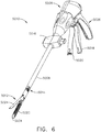
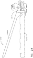
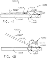
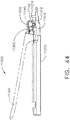
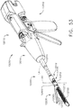
- FIGS. 6-8 depict a previous surgical cutting and fastening instrument 5010 that is configured to generate rotary drive motions for operating a surgical end effector 5012.
- the endoscopic surgical instrument 5010 comprises a handle 5006, a shaft 5008, and an articulating surgical end effector 5012 pivotally connected to the shaft 5008 at an articulation pivot 5014.
- An articulation control 5016 may be provided adjacent to the handle 5006 to effect rotation of the end effector 5012 about the articulation pivot 5014. It will be appreciated that various embodiments may include a non-pivoting end effector, and therefore may not have an articulation pivot 5014 or articulation control 5016.
- the handle 5006 of the instrument 5010 may include a closure trigger 5018 and a firing trigger 5020 for actuating the end effector 5012. It will be appreciated that instruments having end effectors directed to different surgical tasks may have different numbers or types of triggers or other suitable controls for operating the end effector 5012.
- a clinician or operator of the instrument 5010 may articulate the end effector 5012 relative to the shaft 5008 by utilizing the articulation control 5016, as described in more detail in pending U.S. Patent No. 7,670,334 , entitled SURGICAL INSTRUMENT HAVING AN ARTICULATING END EFFECTOR, the entire disclosure of which is incorporated herein by reference.
- the end effector 5012 includes in this example, among other things, a staple channel 5022 and a pivotally translatable clamping member, such as an anvil 5024, which are maintained at a spacing that assures effective stapling and severing of tissue clamped in the end effector 5012.
- the handle 5006 includes a pistol grip 5026 toward which the closure trigger 5018 is pivotally drawn by the clinician to cause clamping or closing of the anvil 5024 towards the staple channel 5022 of the end effector 5012 to thereby clamp tissue positioned between the anvil 5024 and channel 5022.
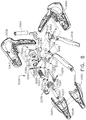
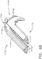
- the end effector 5012 includes, in addition to the previously-mentioned channel 5022 and anvil 5024, a cutting instrument 5032, a sled 5033, a staple cartridge 5034 that is removably seated in the channel 5022, and a helical screw shaft 5036.
- the cutting instrument 5032 may be, for example, a knife.
- the anvil 5024 includes pivot pins 5025 that are movably supported in corresponding slots in the channel 5022.
- the anvil 5024 includes a tab 5027 at its proximate end that is inserted into a component of the mechanical closure system (described further below) to open and close the anvil 5024.
- the shaft 5008 includes a proximal closure tube 5040 and a distal closure tube 5042 pivotably linked by a pivot link 5044.
- the distal closure tube 5042 includes an opening 5045 into which the tab 5027 on the anvil 5024 is inserted in order to open and close the anvil 5024, as further described below.
- Disposed inside the closure tubes 5040, 5042 may be a proximate spine tube 5046.
- Disposed inside the proximate spine tube 5046 may be a main rotational (or proximate) drive shaft 5048 that communicates with a secondary (or distal) drive shaft 5050 via a bevel gear assembly 5052a-c.
- the secondary drive shaft 5050 is connected to a drive gear 5054 that engages a proximate drive gear 5056 of the helical screw shaft 5036.
- the vertical bevel gear 5052b may sit and pivot in an opening 5057 in the distal end of the proximate spine tube 5046.
- a distal spine tube 5058 may be used to enclose the secondary drive shaft 5050 and the drive gears 5054, 5056.
- a bearing 5038 positioned at a distal end of the staple channel 5022, receives the helical screw shaft 5036, allowing the helical screw shaft 5036 to freely rotate with respect to the channel 5022.
- the helical screw shaft 5036 may interface a threaded opening (not shown) of the knife 5032 such that rotation of the helical screw shaft 5036 causes the knife 5032 to translate distally or proximately (depending on the direction of the rotation) through the staple channel 5022.
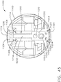
- the handle 5006 includes exterior lower side pieces 5059, 5060 and nozzle pieces 5061, 5062 that fit together to form, in general, the exterior of the handle 5006.
- a battery 5064 such as a Li ion battery, may be provided in the pistol grip portion 5026 of the handle 5006.
- the battery 5064 powers a motor 5065 disposed in an upper portion of the pistol grip portion 5026 of the handle 5006.
- the motor 5065 may drive a 90° bevel gear assembly 5066 comprising a first bevel gear 5068 and a second bevel gear 5070.
- the bevel gear assembly 5066 may drive a planetary gear assembly 5072.
- the planetary gear assembly 5072 may include a pinion gear 5074 connected to a drive shaft 5076.
- the pinion gear 5074 may drive a mating ring gear 5078 that drives a helical gear drum 5080 via a drive shaft.
- a ring 5084 may be threaded on the helical gear drum 5080.
- the handle 5006 may include a middle handle piece 5104 adjacent to the upper portion of the firing trigger 5020.
- the handle 5006 also may comprise a bias spring 5112 connected between posts on the middle handle piece 5104 and the firing trigger 5020.
- the bias spring 5112 may bias the firing trigger 5020 to its fully open position. In that way, when the operator releases the firing trigger 5020, the bias spring 5112 will pull the firing trigger 5020 to its open position.
- the distal end of the helical gear drum 5080 includes a distal drive shaft 5120 that drives a ring gear 5122, which mates with a pinion gear 5124.
- the pinion gear 5124 is connected to the main drive shaft 5048 of the main drive shaft assembly.
- the ring 5084 threaded on the helical gear drum 5080 may include a post 5086 that is disposed within a slot 5088 of a slotted arm 5090.
- the slotted arm 5090 has an opening 5092 in its opposite end 5094 that receives a pivot pin 5096 that is connected between the handle exterior side pieces 5059, 5060.
- the pivot pin 5096 is also disposed through an opening 5100 in the firing trigger 5020 and an opening 5102 in the middle handle piece 5104.
- the middle handle piece 5104 includes a backside shoulder 5106 that engages the slotted arm 5090.
- the middle handle piece 5104 also has a forward motion 5107 stop that engages the firing trigger 5020.
- the movement of the slotted arm 5090 is controlled by rotation of the motor 5065.
- the middle handle piece 5104 will be free to rotate counter clockwise.
- the firing trigger 5020 will engage the forward motion stop 5107 of the middle handle piece 5104, causing the middle handle piece 5104 to rotate counter clockwise.
- the middle handle piece 5104 will only be able to rotate counter clockwise as far as the slotted arm 5090 permits. In that way, if the motor 5065 should stop rotating for some reason, the slotted arm 5090 will stop rotating, and the user will not be able to further draw in the firing trigger 5020 because the middle handle piece 5104 will not be free to rotate counter clockwise due to the slotted arm 5090.
- the closure system includes a yoke 5250 connected to the closure trigger 5018.
- a pivot pin 5252 is inserted through aligned openings in both the closure trigger 5018 and the yoke 5250 such that they both rotate about the same point.
- the distal end of the yoke 5250 is connected, via a pin 5254, to a first closure bracket 5256.
- the first closure bracket 5256 connects to a second closure bracket 5258.
- the instrument 5010 also includes a closure drive shaft 5260 disposed inside the proximal closure tube 5040.
- the closure drive shaft 5260 may include a window 5261 into which a post 5263 on one of the handle exterior pieces, such as exterior lower side piece 5059 in the illustrated embodiment, is disposed to fixedly connect the closure drive shaft 5260 to the handle 5006. In that way, the proximal closure tube 5040 is capable of moving longitudinally relative to the closure drive shaft 5260.
- the closure drive shaft 5260 may also include a distal collar 5267 that fits into a cavity in proximate spine tube 5046 and is retained therein by a cap.
- the closure brackets 5256, 5258 cause the proximal closure tube 5040 to move distally (i.e., away from the handle end of the instrument 5010), which causes the distal closure tube 5042 to move distally, which causes the anvil 5024 to rotate about the pivot pins 5025 into the clamped or closed position.
- the proximal closure tube 5040 is caused to slide proximately, which causes the distal closure tube 5042 to slide proximately, which, by virtue of the tab 5027 being inserted in the opening 5045 of the distal closure tube 5042, causes the anvil 5024 to pivot about the pivot pins 5025 into the open or unclamped position.
- an operator may clamp tissue between the anvil 5024 and channel 5022, and may unclamp the tissue following the cutting/stapling operation by unlocking the closure trigger 5018 from the locked position.
- the instrument 10010 includes a housing 10012 that comprises a handle 10014 that is configured to be grasped, manipulated and actuated by the clinician.
- the instrument 10010 includes a shaft assembly 10200 that has a surgical end effector 10300 operably coupled thereto that is configured to perform one or more surgical tasks or procedures.
- the shaft assembly 10200 comprises an interchangeable shaft assembly that is intended to be removably couplable to the handle assembly 10014 in the various manners disclosed herein.
- the shaft assembly 10200 may also comprise a dedicated shaft assembly that is not intended to be removed from the handle 10014. Only those specific components necessary to understand the functions and operation of the shaft assembly 10200 will be discussed in further detail below.
- the surgical end effector 10300 comprises an elongate channel 10310 that is configured to operably support a staple cartridge 10400 therein.
- the end effector 10300 also includes an anvil 10500 that is pivotally supported relative to the elongate channel 10310.
- the anvil 10500 may be fabricated using various fabricating techniques described in U.S. Patent Application Serial No. 16/105,101 , entitled METHOD FOR FABRICATING SURGICAL STAPLER ANVILS, the entire disclosure of which is hereby incorporated by reference herein.
- the shaft assembly 10200 may further include an articulation joint 10250 that facilitates articulation of the surgical end effector 10300 about an articulation axis AA that is transverse to a longitudinal shaft axis LA.
- Other shaft assemblies may not be capable of articulation.
- the shaft assembly 10200 comprises a proximal outer shaft tube or member 10210 that extends distally from a nozzle assembly 10202.
- a proximal end 10312 of the elongate channel comprises a tubular portion 10314 that is similar in size to the proximal outer shaft tube 10120 and is coupled to the distal end of the proximal outer shaft tube 10210 to form the articulation joint 10250.
- the articulation joint 10250 includes a double pivot shaft assembly 10252. See FIGS. 11 and 12 .
- the tubular portion 10314 of the elongate channel 10310 includes upper and lower proximally projecting tangs 10316, 10318. See FIG. 11 .
- An upper double pivot link 10320 includes upwardly projecting distal and proximal pivot pins that engage respectively an upper pin hole in the upper proximally projecting tang 10316 and an upper distal pin hole in an upper distally projecting tang 10212 on the proximal outer shaft tube 10210.
- a lower double pivot link 10322 includes downwardly projecting distal and proximal pivot pins that engage respectively a lower distal pin hole in the lower proximally projecting tang 10318 and a lower proximal pin hole in a lower distally projecting tang 10214 in the proximal outer shaft tube 10210. See FIG. 11 .
- the shaft assembly 10200 also includes an internal spine member 10230 that is pivotally coupled to an insert assembly 10330 that is received within the tubular portion 10314 of the elongate channel 10310 and is attached thereto by, for example, welding, adhesive, fasteners, etc.
- a proximal end of the internal spine member 10230 may be rotatably coupled to a chassis (not shown) within the nozzle assembly 10202 in the various manners disclosed herein, for example.
- the distal end of the internal spine member 10230 may be pinned to the insert assembly 10330 to facilitate pivotal travel of the elongate channel 10310 relative to the internal spine member 10230.
- the surgical end effector 10300 is selectively articulatable about the articulation axis AA by an articulation system 10260.
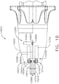
- the articulation system 10260 includes an articulation motor 10262 that is operably supported in the nozzle assembly 10202, for example. See FIG. 10 .
- the articulation motor 10262 may be operably supported in the housing 10012 or handle 10014 or other portion of a robotic system. Referring to FIG. 10 , the articulation motor 10262 is coupled to an articulation drive gear 10264 that is in meshing engagement with a drive gear rack 10266 that is attached to or otherwise formed in a proximal articulation driver 10268.
- a distal end of the proximal articulation driver 10268 is pivotally coupled to a distal articulation link 10270.
- an offset attachment lug 10272 is formed on a distal end 10271 of the proximal articulation driver 10268.
- a pivot hole is formed in the offset attachment lug 10272 and is configured to pivotally receive therein a proximal link pin 10276 formed on the proximal end 10274 of the distal articulation link 10270.
- a distal end 10278 of the distal articulation link 10270 includes a pivot hole that is configured to pivotally receive therein a channel pin 10332 formed on the insert assembly 10330.
- Operation of the articulation motor 10262 will cause axial movement of the proximal articulation driver 10268.
- Axial movement of proximal articulation driver 10268 will apply articulation motions to the elongate channel 10310 to thereby cause the surgical end effector 10300 to articulate about the articulation axis AA relative to the internal spine member 10230.
- Other articulation systems and arrangements may be employed in the various manners disclosed herein. In other embodiments, the surgical end effector may not be articulatable.
- the surgical end effector 10300 includes a firing member that is axially movable within the surgical end effector 10300 between a starting position and an ending position.
- the firing member may be configured to sever tissue that is clamped between the anvil 10500 and a surgical staple cartridge 10400 that is operably supported in the elongate channel 10310.
- the staple cartridge 10400 includes lines of surgical staples or fasteners that are operably supported on corresponding drivers that are movably supported in the cartridge.
- the firing member As the firing member is driven distally, the firing member cooperates with a sled or camming assembly that is supported in the staple cartridge that serves to advance the drivers in a direction toward the closed anvil which causes the staples or fasteners supported thereon to pierce through the clamped tissue into forming contact with the underside of the closed anvil.
- a sled or camming assembly that is supported in the staple cartridge that serves to advance the drivers in a direction toward the closed anvil which causes the staples or fasteners supported thereon to pierce through the clamped tissue into forming contact with the underside of the closed anvil.
- the surgical instrument 10010 also employs a firing system 10600 that is configured to apply rotary drive motions to the firing member to drive the firing member between the starting and end positions.
- the firing system 10600 includes a firing motor 10602 that is operably supported in the nozzle assembly 10202, for example.
- the firing motor 10602 may be operably supported in the housing or handle or other portion of a robotic system.
- the firing motor 10602 is coupled to a firing drive gear 10604 that is in meshing engagement with a driven gear 10606 that is attached to or otherwise formed in rotary firing drive shaft 10610.
- the firing drive shaft 10610 may be flexible to permit articulation of the surgical end effector 10300 in the manner described above.
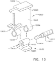
- FIG. 13 depicts one example of a rotary driven firing member 10620 that may be employed in the surgical end effector 10300.
- the firing member 10620 comprises a body portion 10622 that includes two downwardly extending hollow mounting portions 10624 that are unthreaded and spaced from each other to receive a threaded drive nut 10630 therebetween.
- the threaded drive nut 10630 is threaded onto a threaded portion 10612 of the rotary firing drive shaft 10610.
- a distal end 10614 of the rotary firing drive shaft 10610 may be configured to be rotatably supported in a bearing (not shown) that is housed within the elongate channel and is configured to rotatably support the rotary firing drive shaft 10610 therein.
- the drive nut 10630 includes a vertical tab portion 10632 that is sized to extend through an axial slot in the bottom of the elongate channel.
- Two laterally extending channel engagement flanges 10634 are formed on the threaded drive nut 10630 and are configured to engage the bottom of the elongate channel.
- two laterally extending anvil engagement tabs 10626 are formed on the top of the firing member body 10622 and are configured to engage corresponding ledges formed in the anvil 10500 as the firing member 10620 is axially moved within the end effector 10300.
- the firing member 10620 includes a camming sled engagement feature 10628 that is configured to operably engage a camming assembly that is movably stored in the staple cartridge.
- the camming sled or camming assembly may include a tissue cutting member or a tissue cutting feature attached to the firing member 10620.
- the firing member 10620 may be stored within an unfired staple cartridge and is configured to be seated on the threaded drive nut 10630 when the cartridge is operably installed within the elongate channel.
- a variety of other rotary driven firing member arrangements may also be employed.
- firing and tissue cutting members that are permanently threaded onto the rotary firing drive shaft may also be employed.
- the firing member 10620 may serve to maintain a desired amount of tissue gap between a deck surface 10402 on the staple cartridge 10400 and a staple forming undersurface 10502 on the anvil 10500. See FIG. 9 .
- the surgical instrument 10010 also includes a rotary driven closure system 10700 that is configured to apply rotary closure motions to the anvil 10500.
- the rotary driven closure system 10700 comprises a closure motor 10702 that is operably supported in the nozzle assembly 10202, for example.
- the closure motor 10702 may be operably supported in the housing or handle or other portion of a robotic system.
- the closure motor 10702 is coupled to a closure drive gear 10704 that is in meshing engagement with a driven gear 10706 that is attached to or otherwise formed in rotary closure drive shaft 10710.
- the closure drive shaft 10710 may be flexible to permit articulation of the surgical end effector 10300 in the manner described above.
- the surgical end effector 10300 includes the anvil 10500 that includes a proximally-extending mounting tab 10510 that is configured to be pivotally attached to a distal insert portion 10334 of the insert assembly 10330.
- the distal insert portion 10334 may be separate from the insert assembly 10330 and otherwise be attached to the proximal end portion 10312 of the elongate channel 10310 by welding, adhesive, fasteners, etc.
- the distal insert portion 10334 may actually comprise a portion of the elongate channel 10310 and be integrally formed therewith.
- the anvil mounting tab 10510 includes a distal portion 10512 through which a transverse slot 10514 extends therethrough and is aligned with a transverse slot 10336 in the distal insert portion 10334 as well as a slot 10315 in the tubular portion 10314 of the elongate channel 10310. See FIG. 18 .
- the anvil mounting tab 10510 is pivotally attached to the elongate channel 10310 by a rivet 10340.
- the anvil mounting tab 10510, as well as the distal insert portion 10334, are sufficiently robust to provide a sufficient amount of strength where the rivet 10340 operates which provides the ability to locate the pivoting attachment point above the centerline or midpoint of the end effector and thereby afford sufficient room therein for the firing member components and rotary drive components.
- Orbit forming of the rivet 10340 pivotally cinches the anvil mounting tab 10510 to the elongate channel 10310 and can remove excessive play or movement (tolerance slop) which serves to place the rivet 10340 in complete or significantly complete shear for resistance against closure loads.
- the relatively broad contact between such components may also serve to prevent or minimize twisting between the anvil mounting tab 10510 and the elongate channel 10310.
- the anvil 10500 is asymmetrically coupled to the elongate channel 10310. Stated another way, the location in which the anvil 10500 is attached to the elongate channel 10310 is laterally offset from the end effector centerline EC.
- the rivet 10340 comprises solid core rivet with a diameter of 0.05" - 0.1" and an orbit formed head 10342 on one end of the rivet shank 10344 and a machined head 10346 on the other end of the rivet shank 10344.
- the riveting is done in such a way that the rivet 10340 would hold a final formed height that would ensure intimate contact between the anvil mounting tab 10510 and the corresponding attachment portions of the elongate channel 10310.
- the "orbit formed" head 10342 would swell the rivet shank 10344 on that side of the anvil mounting tab 10510 and elongate channel portions which may prevent the rivet from rotating relative to that part while the other "pre-machined" side 10346 would not have a swelled shank portion which may permit the adjacent components to rotate.
- the rivet 10340 is fixed relative to the channel portion to avoid a condition wherein the anvil pivots freely relative to the insert and elongate channel.
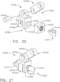
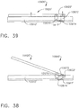
- closure system 10700 that is configured to apply opening and closure motions to the anvil 10500.
- closure system 10700 comprises a closure linkage assembly 10716 that is pivotally coupled to the anvil mounting tab 10510 for pivotal travel relative thereto about a common closure axis CA.
- the closure drive shaft 10710 comprises a threaded drive segment 10714 that is configured to threadably engage a drive nut 10730 that is supported by a drive yoke 10720.
- the drive yoke 10720 includes two yoke arms 10722 that have unthreaded holes 10724 therethrough to permit the closure drive shaft 10710 to pass therethrough.
- the drive nut 10730 has a threaded hole 10732 therethrough that is threaded onto the threaded drive segment 10714 of the closure drive shaft 10710 and is received between the yoke arms 10722.
- a closure link 10740 is pivotally coupled to the drive yoke 10720 by a pin 10742.
- the closure link 10740 is also pivotally attached (pinned) to the anvil mounting tab 10510 by a pin 10744. See FIG. 19 .
- a spacer member 10746 is provided to fill the space between the closure link 10740 and spaced arms 10516 of the anvil mounting tab 10510.
- the closure link may be sized and shaped to fill in that space.
- a retainer tab 10311 is formed in the elongate channel 10310 to define an axial trough 10313 for slidably receiving the drive yoke 10720 therein.
- Rotation of the rotary closure drive shaft 10710 in a first rotary direction will cause the drive yoke 10720 to move distally and cause the closure link 10740 to pull the anvil mounting tab 10510 in an opening direction which causes the anvil 10500 to pivot to an open position about the pivot axis PA.
- the rotary driven closure system 10700 may be actuated during the actuation of the rotary driven firing system 10600 such that the closure system 10700 continues to apply additional closure motions to the anvil as the firing member is axially driven through the staple cartridge.
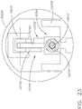
- FIGS. 22 and 23 illustrate an alternate closure drive arrangement wherein the anvil mounting tab 10510' of the anvil 10500' is generally centrally supported within the end effector.
- the anvil mounting portion 10510' may be pivotally coupled to the elongate channel 10310' in the manner described above.
- the rotary closure drive shaft 10710' is hollow and concentrically supports the rotary firing shaft 10610' therein.
- the rotary closure drive shaft 10710' and the rotary firing drive shaft 10610' are centrally disposed within the elongate channel 10310' as can be seen in FIG. 23 .
- the rotary firing drive shaft 10610' rotatably extends through the rotary closure drive shaft 10710' and includes a distal threaded portion 10612' that is configured to threadably drive the firing member 10620 in the manner described above, for example.
- FIGS. 22 and 23 employs a rotary actuated closure linkage assembly 10716' that is configured to apply opening and closure motions to the anvil 10500'.
- the closure linkage assembly 10716' comprises a proximal drive yoke assembly 10720' and a distal drive yoke assembly 10750.
- the proximal drive yoke assembly 10720' includes two spaced yoke arms 10722' that have unthreaded holes 10724' therethrough to permit the closure drive shaft 10710' to pass therethrough.
- a proximal drive nut 10730' is received between the spaced yoke arms 10722' and includes a threaded hole for threadably engaging a proximal thread segment 10712' on the rotary closure drive shaft 10710'.
- the proximal drive yoke assembly 10720' is pivotally coupled to a proximal closure link 10740' that is pivotally pinned to the anvil mounting portion 10510'.
- the distal drive yoke assembly 10750 includes two spaced yoke arms 10752 that have unthreaded holes 10754 therethrough to permit the closure drive shaft 10710' to pass therethrough.
- a distal drive nut 10760 is received between the spaced yoke arms 10752 and includes a threaded hole for threadably engaging a distal thread segment 10714' on the rotary closure drive shaft 10710'.
- the proximal threaded segment 10712' and the distal threaded segment 10714' are thread in opposite directions.
- the distal drive yoke assembly 10750 is pivotally coupled to a U-shaped distal closure link 10770 that is pivotally pinned to the anvil mounting portion 10510'.
- the U-shaped distal closure link 10770 affords the closure linkage assembly 10716' with a symmetric load bearing arrangement.
- Rotation of the rotary closure drive shaft 10710' in a first rotary direction will cause the proximal drive yoke 10720' and the distal drive yoke assembly 10750 to axially move away from each other to pull the anvil mounting tab 10510' in an opening direction causing the anvil 10500' to pivot to an open position about the pivot axis PA.
- rotation of the rotary closure drive shaft 10710' in a second rotary direction will cause the proximal drive yoke 10720' and distal drive yoke assembly 10750 to move towards each other and push the anvil mounting tab 10510' in a closing direction causing the anvil 10500' to pivot to a closed position about the pivot axis PA.
- Such arrangement may serve to apply generally higher closure forces to the anvil 10500'.
- the rotary firing drive shaft 10610' is independently rotatable relative to the rotary closure drive shaft 10710'.
- the rotary driven closure system 10700 may be actuated during the actuation of the rotary driven firing system 10600 such that the closure system 10700 continues to apply additional closure motions to the anvil as the firing member is axially driven through the staple cartridge.
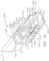
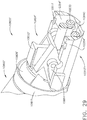
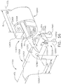
- FIGS. 24-27 illustrate an another surgical end effector 10800 that employs a closure drive arrangement wherein an anvil mounting tab 10804 of an anvil 10802 is centrally supported within the end effector 10800 and two rotary closure shafts 10830 and 10840 are employed to apply closure motions to the anvil 10802.
- a distal portion 10806 of the anvil mounting tab 10804 includes a pair of laterally extending pivot members 10808 that are adapted to be pivotally cradled in pivot cradles 10356 in upstanding walls 10354 of a distal mounting portion of the elongate channel 10310". See FIG. 27 .
- the pivot members 10808 are vertically movable or "floatable" within their corresponding pivot cradles 10356.
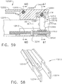
- the rotary firing drive shaft 10610 ( FIG. 26 ) is vertically supported above the rotary closure drive shaft 10710 ( FIGS. 24 and 25 ).
- the rotary firing drive shaft 10610 includes a firing drive gear 10611 that is configured to drivingly engage a driven gear (not shown) on a distal firing drive shaft 10613 that is rotatably supported in the elongate channel 10310" in the various manners described herein. See FIG. 27 .
- a firing member drive nut 10630 is threaded on the distal firing drive shaft 10613 and serves to drive a firing member 10620 within the end effector 10800 as the rotary firing drive shaft 10610 is rotated in the manner described herein.
- the rotary closure drive shaft 10710 includes a closure drive gear 10715 that is centrally disposed between a right distal closure shaft 10830 and a left distal closure shaft 10840.
- the right distal closure shaft 10830 includes a right driven gear 10832 that is in meshing engagement with the closure drive gear 10715 and the left distal closure shaft 10840 includes a left driven gear 10842 that is also in meshing engagement with the closure drive gear 10715.
- Rotation of the rotary closure drive shaft 10710 will result in the rotation of the right distal closure shaft 10830 in a first rotary direction and the rotation of the left distal closure shaft 10840 in a second rotary direction.
- FIGS. 24-26 employs a rotary actuated right closure linkage assembly 10850 and a rotary actuated left closure linkage assembly 10860 that are configured to apply opening and closure motions to the anvil 10802.
- the right closure linkage assembly 10850 comprises a proximal drive nut assembly 10852 that is threaded onto the right distal closure shaft 10830 and is coupled to a right closure link 10854 that is attached to the anvil mounting tab 10804.
- the left closure linkage assembly 10860 comprises a left drive nut assembly 10862 that is threaded onto the left distal closure shaft 10840 and is coupled to a left closure link 10864 that is attached to the anvil mounting tab 10804.
- the diameter D of the right distal closure shaft 10830 and the left distal closure shaft 10840 may be approximately 0.078". See FIG. 26 .
- the space "E” between the right drive nut assembly 10852 and the left drive nut assembly 10862 may be approximately 0.093" and the width "W" of the channel 10310" may be approximately 0.256".
- Rotation of the rotary closure drive shaft 10710 in a first rotary direction will cause the right drive nut assembly 10852 and the left drive nut assembly 10862 to move in a synchronized fashion to open the anvil 10802 in a balanced uniform manner.
- Rotation of the rotary closure drive shaft 10710 in a second rotary direction will cause the right drive nut assembly 10852 and the left drive nut assembly 10862 to move in a synchronized fashion to close the anvil 10802 in a balanced uniform manner and reduce any twisting moment on the anvil 10802 as the anvil 10802 is pivoted closed.
- the anvil mounting tab 10804 includes a domed or spherical distal surface portion 10809.
- a closure ring 10811 ( FIG. 27 ) is movably journaled on the spherical distal surface portion 10809.
- the closure ring 10811 serves to constrain the anvil 10802 to the elongate channel 10310".
- FIG. 24 illustrates the anvil 10802 in a closed position.
- the links 10854 and 10864 are nearly vertical (perpendicular) to the end effector axis EC.
- FIG. 25 illustrates the anvil 10802 in an open position.
- the anvil 10802 is pivoted upward at an angle that is approximately 20° from the horizontal as shown.
- the links 10854 and 10864 are nearly horizontal (relative to each other) which results in the application of a reduced amount of closure force than was established when the anvil was moved to the closed position.
- the links 10854 and 10864 may have a length L of approximately 0.150", for example.
- the rotary driven closure system 10700 may be actuated during the actuation of the rotary driven firing system 10600 such that the closure system 10700 continues to apply additional closure motions to the anvil as the firing member is axially driven through the staple cartridge.
- FIGS. 28-31 illustrate another surgical end effector 10800' that employs a closure drive arrangement wherein an anvil mounting tab 10804' of an anvil 10802' is also centrally supported within the end effector 10800' and two rotary closure shafts 10830 and 10840 are employed to apply closure motions to the anvil 10802'. See FIG. 29 .
- the anvil 10802' may be fabricated using various fabricating techniques described in U.S. Patent Application Serial No. 16/105,101 , entitled METHOD FOR FABRICATING SURGICAL STAPLER ANVILS, the entire disclosure of which is hereby incorporated by reference herein.
- a distal portion 10806' of the anvil mounting tab 10804' includes a pair of laterally extending pivot members 10808' that are adapted to be pivotally cradled in pivot cradles 10356" in upstanding walls 10354" of a distal mounting portion 10352" of the elongate channel 10310". See FIGS. 30 and 31 .
- the pivot members 10808' are vertically movable or "floatable” within their corresponding pivot cradles 10356".
- the rotary firing drive shaft 10610 (similar to that shown in FIG. 26 ) is vertically supported above the rotary closure drive shaft 10710 ( FIGS. 24 and 25 ) in the elongate shaft.
- the rotary firing drive shaft (not shown) includes a firing drive gear (not shown) that is configured to drivingly engage a driven gear (not shown) on a distal firing drive shaft 10613' that is rotatably supported in the elongate channel 10310" in the various manners described herein. See FIGS. 28 and 29 .
- the distal firing drive shaft 10613' is configured to threadably drive a firing member 10620' within the end effector 10800' as the rotary firing drive shaft and distal firing drive shaft 10613' are rotated in the manners described herein.
- the rotary closure drive shaft 10710 includes a closure drive gear 10715 that is centrally disposed between a right distal closure shaft 10830 and a left distal closure shaft 10840. See FIGS. 29-31 .
- the right distal closure shaft 10830 includes a right driven gear that is in meshing engagement with the closure drive gear 10715 and the left distal closure shaft 10840 includes a left driven gear 10842 that is also in meshing engagement with the closure drive gear 10715.
- Rotation of the rotary closure drive shaft 10710 will result in the rotation of the right distal closure shaft 10830 in a first rotary direction and the rotation of the left distal closure shaft 10840 in a second rotary direction.
- the right closure linkage assembly 10850 comprises a proximal drive nut assembly 10852 that is threaded onto the right distal closure shaft 10830 and is coupled to a right closure link 10854 that is attached to the anvil mounting tab 10804'.
- the left closure linkage assembly 10860 comprises a left drive nut assembly 10862 that is threaded onto the left distal closure shaft 10840 and is coupled to a left closure link 10864 that is attached to the anvil mounting tab 10804'.
- Rotation of the rotary closure drive shaft 10710 in a first rotary direction will cause the right drive nut assembly 10852 and the left drive nut assembly 10862 to move in a synchronized fashion to open the anvil 10802' in a balanced uniform manner.
- Rotation of the rotary closure drive shaft 10710 in a second rotary direction will cause the right drive nut assembly 10852 and the left drive nut assembly 10862 to move in a synchronized fashion to close the anvil 10802' in a balanced uniform manner and reduce any twisting moment on the anvil 10802' as the anvil 10802' is pivoted closed.
- the anvil mounting tab 10804' includes a domed or spherical distal surface portion 10809'.
- a closure ring 10811' is movably journaled on the spherical distal surface portion 10809'.
- the closure ring 10811' serves to constrain the anvil 10802 to the elongate channel 10310".
- a pivot spring 10813' is seated in each of the cradles 10356" which serves to bias the pivot members 10808' upward in their respective cradles 10356".
- a distal portion of the spherical surface portion 10809' comprises a shallow notch area 10815' that provides additional clearance for the closure ring 10811' to enable the anvil 10802' to pivot further open, for example, wherein the undersurface 10803' of the anvil 10802' is at least 20° (angle A) from the deck surface of the surgical staple cartridge seated within the channel 10310". See FIG. 30 .
- the radial distance between the center of the pivot members 10808' to the spherical surface 10809' is designated as "r" in FIGS. 30 and 31 .
- the radial distance from the centerline of the pivot members 10808' to the notched area 10815' is designated as "r"', wherein r' > r.
- FIG. 30 illustrates the anvil 10802' in a fully open position.
- the closure ring 10811' is approximately axially aligned with the pivot members 10808' which serves to drive the pivot members 10808' into the bottom of their respective cradle 10356"and compress the pivot spring 10813' therein.
- FIG. 31 illustrates the anvil 10802' in the closed position wherein the closure ring 10811' is slightly proximally axially offset from the pivot members 10808' which permits the pivot springs 10813' to bias the pivot members 10808' upward within their respective cradles 10356".
- the closure rings in these embodiments essentially encircle the corresponding anvil and elongate channel portions.
- the closure ring is permitted to move proximally to distally a small amount (e.g., 0.0" - 0.1") while being spring biased to the distal position.
- the ring does not induce closure but merely constrains the anvil and channel from moving apart vertically allowing a pivoting motion to occur between the two components.
- Such arrangement facilitates use of a thicker anvil particularly in the anvil mounting area which may improve anvil strength and reliability.
- This configuration may further enable the jaws (anvil and channel) to pivot in a fashion that improves the moment arm condition of the anvil proximal to the pivot location and facilitate opening of the end effector to greater opening angles.
- the rotary driven closure system 10700 may be actuated during the actuation of the rotary driven firing system 10600 such that the closure system 10700 continues to apply additional closure motions to the anvil as the firing member is axially driven through the staple cartridge.
- FIGS. 33-35 illustrate another end effector 10900 that employs an alternate closure drive arrangement for opening and closing an anvil 10920 relative to an elongate channel 10910 thereof.
- the anvil 10920 includes an anvil mounting tab 10922 that protrudes proximally along a centerline of the anvil 10920 and is pivotally coupled to a proximal end 10912 of the elongate channel 10910 in the various manners disclosed herein.
- the anvil 10920 may be fabricated using various fabricating techniques described in U.S. Patent Application Serial No. 16/105,101 , entitled METHOD FOR FABRICATING SURGICAL STAPLER ANVILS, the entire disclosure of which is hereby incorporated by reference herein.
- a rotary closure drive shaft 10710' is hollow and concentrically supports a rotary firing drive shaft 10610' therein.
- the rotary closure drive shaft 10710' and the rotary firing drive shaft 10610' are centrally disposed within the elongate channel 10910 as can be seen in FIG. 33 .
- the rotary firing drive shaft 10610' rotatably extends through the rotary closure drive shaft 10710' and includes a distal threaded portion 10612' that is configured to threadably drive a firing member 10620 in the manner described above, for example.
- a closure shuttle 10940 is supported for axial travel within the elongate channel 10910.
- the closure shuttle 10940 is threadably journaled on the threaded closure drive shaft 10710' such that rotation of the threaded closure drive shaft 10710' in a first direction causes the closure shuttle 10940 to move distally and rotation of the threaded closure drive shaft 10710' in a second rotary direction causes the closure shuttle 10940 to move proximally within the elongate channel 10910.
- a right closure link 10950 and a left closure link 10960 are pivotally coupled to the anvil mounting tab 10922.
- the right closure link 10950 also includes an actuation end 10952 that is received within a corresponding right actuation notch 10942 in the closure shuttle 10940 and the left closure link 10960 includes an actuation end 10962 that is received within a corresponding left actuation notch 10944 in the closure shuttle 10940.
- a right drive notch 10954 is provided in the actuation end 10952 of the right closure link 10950 and a left drive notch 10964 is provided in the actuation end 10962 of the left closure link 10960.
- the drive notches 10954, 10964 are configured to drivingly engage the actuation notches 10942, 10944, respectively.
- FIGS. 33 and 35 illustrate the closure shuttle 10940 in a proximal-most, retracted position.
- the right and left closure links 10950, 10960 push up on the anvil mounting tab 10922 and cause the anvil 10920 to pivot about the pivot axis PA to a closed position.
- the closure shuttle 10940 has been moved to its distal-most, extended position, the right and left closure links 10950, 10960 pull the anvil tab 10922 downward and pivot the anvil 10920 to the open position as shown in FIG. 34 .
- FIG. 36 illustrates some exemplary dimensions of various components of the surgical end effector 10900.
- the overall height "H" may be approximately 0.500.
- the anvil height "AH" may be approximately 0.120".
- the rivet passage may have a diameter "PD" of approximately 0.070" and the base height "BH" may be approximately 0.310", for example.
- the hollow closure drive shaft 10710' may have an internal diameter "ID" of approximately 0.100" and an unthreaded outer diameter "UTD” of approximately 0.129” and a threaded outer diameter "TD” of approximately 0.164":
- the firing drive shaft 10610' may have an unthreaded diameter "UTD'" of approximately 0.0668" and a threaded outer diameter "TD'” of approximately 0.0854", for example.
- Other diameters, component sizes and dimensions may also be employed.
- FIGS. 38 and 39 are diagrammatical depictions of an end effector 10900' that employs alternative closure link arrangements.
- a distal closure link (or links) 10970 are pivotally pinned or otherwise pivotally coupled to an anvil 10920' and an elongate channel 10910'.
- proximal closure links 10972 are attached to an anvil mounting tab portion 10922' and are slidably coupled via a corresponding pin 10974 that is received in a corresponding axial slot 10911' in the elongate channel 10910' or in a closure shuttle or other member (not shown) that is configured to move the proximal closure links 10972 between a first position ( FIG. 38 ) corresponding to an open position of the anvil 10920' and a second position ( FIG. 39 ) corresponding to the closed position of the anvil 10920'.
- FIG. 40 and 41 are diagrammatical depictions of an end effector 10900" that employs alternative closure link arrangements.
- a proximal end portion 10923" of an anvil 10920" is pivotally coupled to an elongate channel 10910" by proximal mounting links 10980.
- the proximal mounting links 10980 (only one is shown in the Figures) are pivotally attached to the elongate channel 10910" for pivotal travel relative thereto about a lower pivot axis LPA.
- the proximal mounting links 10980 are also pivotally coupled to the proximal end portion 10923" for pivotal travel relative thereto about an anvil pivot axis APA.
- the end effector 10900" further includes a closure linkage assembly 10982 that comprises at least one distal link 10984 and one proximal link 10986.
- the closure linkage assembly 10982 comprises a pair of distal links 10984 (one on each side of the elongate channel) and a pair of proximal links 10986 (one on each side of the elongate channel).
- the distal link(s) 10984 is attached to the anvil 10920" for pivotal travel about the anvil pivot axis APA as well as to the corresponding proximal link(s) 10986.
- the other end of the proximal link(s) is pivotally attached to the elongate channel 10910".
- the closure linkage assembly 10982 is actuated by a slider pin or pins 10988 that are constrained to move axially either in the elongate channel or in a closure shuttle or other member (not shown) that is configured to move the pin(s) 10988 between a first position ( FIG. 40 ) corresponding to an open position of the anvil 10920" and a second position ( FIG. 41 ) corresponding to the closed position of the anvil 10920".
- the closure linkage assembly 10982 could comprise a compound set of links. Such arrangement may have interactive surfaces that limit the rotation of one linkage with respect to the second linkage.
- the closure of the anvil 10920" for a given rate of angular rotation could induce first and second closure rate as well establish different mechanical advantages for closing the anvil.
- a rapid rate of closure may be initially employed for an initial portion of the closure stroke of the closure actuator and then a slower rate of closure may be employed during the remaining portion of the closure stroke which may result in the application of increased closure forces to the anvil.
- FIG. 42 and 43 are diagrammatical depictions of an end effector 10900"' that employs alternative closure link arrangements.
- a proximal end portion 10923"' end portion of an anvil 10920"' is pivotally coupled to the elongate channel 10910"' by proximal mounting links 10980.
- the proximal mounting links 10980 (only one is shown in the Figures) are pivotally attached to the elongate channel 10910"' for pivotal travel relative thereto about a lower pivot axis LPA.
- the proximal mounting links 10980 are also pivotally coupled to the proximal end portion 10923"' for pivotal travel relative thereto about an anvil pivot axis APA.
- the end effector 10900"' further includes a closure linkage assembly 10990 that comprises at least one distal link 10992 and one proximal link 10994.
- the closure linkage assembly 10990 comprises a pair of distal links 10992 (one on each side of the elongate channel) and a pair of proximal links 10994 (one on each side of the elongate channel).
- the distal link(s) 10992 is attached to the anvil 10920'" for pivotal travel about the anvil pivot axis APA as well as to the corresponding proximal link(s) 10994.
- the other end of the proximal link(s) is pivotally attached to the elongate channel 10910"'.
- the closure linkage assembly 10990 is actuated by a slider pin or pins 10988 that are constrained to move axially either in a corresponding slot in the elongate channel or in a closure shuttle or other member (not shown) configured to move the pin(s) 10988 between a first position ( FIG. 42 ) corresponding to an open position of the anvil and a second position ( FIG. 43 ) corresponding to the closed position of the anvil.
- the slider pin(s) 10988 is coupled to the proximal link(s) 10994. In the open state, the slider pin(s) 10988 is in the distal-most position ( FIG. 42 ).
- the slider pin(s) 10988 is moved in a proximal direction which pulls the proximal closure link(s) 10994 to the position shown in FIG. 43 wherein the distal closure link(s) 10992 pop over center to retain the anvil 10920"' in the closed state.
- the force vector during closure is provided by the proximal and distal closure links being in compression to thereby resist load generated by the tissue clamped in the end effector during closure.
- FIGS. 44-52 there is shown another surgical end effector 11000 that includes an anvil 11100 that is pivotally supported on an elongate channel 11010 that is configured to operably support a surgical staple cartridge (not shown) therein.
- This arrangement also employs two rotary actuation shafts - one for closure (i.e., moving the anvil and elongate channel between open and closed positions) and one for firing (i.e., axially moving a firing member) within the anvil and elongate channel.
- the anvil 11100 includes an elongate anvil body 11110 and an anvil mounting portion 11140.
- the anvil 11100 may be fabricated using various fabricating techniques described in U.S.
- Patent Application Serial No. 16/105,101 entitled METHOD FOR FABRICATING SURGICAL STAPLER ANVILS, the entire disclosure of which is hereby incorporated by reference herein.
- a pair of anvil trunnions 11142 protrudes laterally from the anvil mounting portion 11140.
- Each anvil trunnion is pivotally supported in a corresponding trunnion cradle 11016 that is formed in a corresponding upstanding wall 11014 of a proximal end portion 11012 of the elongate channel 11010. See FIG. 44 .
- the proximal end portion 11012 of the elongate channel 11010 may be pivotally coupled to an elongate shaft assembly 10200 of a surgical instrument 10010 of the type described herein, for example to facilitate articulation of the end effector 11000. In other arrangements, the elongate channel 11010 may not be capable of articulation.
- the anvil trunnions 11142 may be retained within their respective trunnion cradles 11016 by an anvil retainer (not shown) that may be similar in construction and operation to channel cap or anvil retainer 1290 that was described above.
- the surgical end effector 11000 includes an anvil closure member 11200 and a firing member 11300 that are each independently controlled and axially movable.
- FIG. 47 illustrates one form of a closure member 11200 that may be employed.
- the closure member 11200 includes a vertically extending closure body 11202 that has two bottom channel tabs 10204 laterally protruding therefrom.
- a portion of the closure body 11202 is configured to extend through a slot 11019 in a bottom surface 11018 of the elongate channel 11010 and channel tabs 11204 extend laterally outward to slidably engage the bottom of the channel 11010.
- the closure body 11202 includes a threaded through hole 11208 for threadably engaging a threaded portion 10712 of a rotatable closure drive shaft 10710 for axially driving the closure member 11200 in the various manners described herein.
- the surgical end effector 11000 further includes an axially movable firing member 11300.
- FIG. 48 illustrates one form of a firing member 11300 that may be employed.
- the firing member 11300 includes a vertically extending firing member body 11302 that has a tissue cutting surface 11303 as well as two bottom channel tabs 11304 laterally protruding therefrom.
- a portion of the firing member body 11302 is configured to extend through the slot 11019 in the bottom surface 11018 of the elongate channel 11010 and the channel tabs 11304 extend laterally outward to slidably engage the bottom of the channel 11010. See FIG. 45 .
- the firing member body 11302 includes a threaded through hole 11308 for threadably engaging a threaded portion of a rotatable firing drive shaft such as a firing drive shaft 10610 described above.
- the distal firing shaft 10610 passes through an unthreaded clearance hole 11210 in the closure body 11202. See FIG. 47 .
- the firing drive shaft 10610 extends axially down the elongate channel 11010 and is rotatably supported in a distal end portion thereof by a bearing (not shown) or other arrangement.
- closure drive shaft 10710 may extend axially down the elongate channel 11010 and to be rotatably supported in a distal end portion thereof by a bearing (not shown) or other arrangement.
- the firing member body 11302 similarly has an unthreaded clearance hole 11310 therethrough to accommodate the closure drive shaft 10710. It will be appreciated that in such arrangements, the closure drive shaft 10710 and the firing drive shaft 10610 may be supported in a vertical stacked arrangement so that they may be independently rotatable.
- FIG. 46 illustrates one form of anvil 11100 with portions thereof shown in cross-section.
- the anvil mounting portion 11140 includes a central cross brace 11144 that serves to define an opening 11146 for accommodating the closure member 11200 therein when the closure member 11200 is in its proximal-most position which corresponds to an open position of the anvil 11100.
- the anvil body 11110 defines an elongate slot 11112 for accommodating the firing member body 11302 and closure body 11202 therethrough.
- the firing member 11300 is located distal to the closure member 11200.
- the anvil engagement tabs 11306 on the firing member 11302 are configured to slidably engage corresponding first or lower ledges 11114 that are formed on each side of the slot 11112.
- the lower ledges 11114 taper slightly downward at their proximal ends to accommodate the anvil engagement tabs 11306 on the firing member 11300 when the anvil is pivoted to its open position.
- the anvil engagement tabs 11206 on the closure member 11200 are configured to slidably engage corresponding second or higher ledges 11116 that are formed on each side of the slot 11112. See FIG. 46 .
- the closure drive shaft is rotated to threadably drive the closure member 11200 proximally into its proximal-most position ( FIG. 49 ).
- the closure member 11200 When the closure member 11200 is in its proximal-most position, the anvil engagement tabs 11206 thereon apply a pivotal opening motion to the anvil 11100 to pivot the anvil open.
- the firing member 11300 is in its starting position so that the anvil engagement tabs 11306 of the firing member 11300 do not apply a closure motion to the anvil 11100.
- the closure drive shaft 10710 is rotated in an opposite direction to distally advance the closure member 11200 into a closed position.
- the firing drive shaft 10610 may also be simultaneously rotated to distally advance the firing member 11300 into a starting position.
- the closure member 11200 and the firing member 11300 are in those positions, the anvil 11100 is closed and the firing member 11300 is ready to be fired.
- the user may close the anvil 11100 onto the tissue in the above described manner to ready the end effector to be fired.
- the firing drive shaft 10610 is rotated to drive the firing member 11300 distally into the clamped tissue to cut the tissue and cause the staples stored in the staple cartridge to be formed into the cut tissue on both sides of the cut.
- the closure member 11200 may also be driven distally to apply additional closure motions to the anvil 11100 and elongate channel 11010.
- the closure member 11200 can be advanced with the firing member 11300, stop and then go again.
- the closure member 11200 may be advanced distally at a different rate from the firing member's rate of distal advancement.
- the distance Dc between the closure member 11200 and the firing member 11300 may be controlled to balance the loads experienced during the firing process.
- the closure member 11200 could be moved closer to the firing member 11300 during advancement.
- the vertical loads experienced by the firing member 11300 may be increased by increasing the distance between the firing member 11300 and the closure member 11200.
- the thickness t 1 of the anvil engagement tabs 11206 on the closure member 11200 is greater than the thickness t 2 of the anvil engagement tabs 11306 on the firing member 11300.
- the length L 1 of the anvil engagement tabs 11206 on the closure member 11200 is slightly less than the length L 2 of the anvil engagement tabs 11306 on the firing member 11300.
- the thickness t 3 of the channel tabs 11204 on the closure member 11200 is greater than the thickness t 4 of the channel tabs 11304 on the firing member 11300.
- the length L 1 of the channel tabs 11204 on the closure member 11200 are shorter than the length L 3 of the channel tabs 11304 on the firing member 11300.
- the diameters d 1 of the threaded holes 11208, 11308 may be greater than the diameters d 2 of the unthreaded through holes 11210, 11310.
- the relative attack angles between the anvil engagement tabs 11206, 11306 and their corresponding anvil ledges and the channel tabs 11204, 11304 and their corresponding channel ledges may be varied, the same or different.
- the anvil engagement tabs 11306 on the firing member 11300 are arranged at a slightly higher attack angle relative to their corresponding anvil ledges than the attack angle of the anvil engagement tabs 11206 on the closure member 11200.
- the channel tabs 11204 and 11304 ride on the same ledges that are formed in the bottom of the elongate channel 11010. See FIG. 45 .
- the closure member 11200 and the firing member 11300 have separate acting paths which can permit the closure member to be designed to accommodate larger moment arms from the anvil pivot for better firing efficiency.
- closure member 11200 can be moved away from the firing member 11300 to gain a significant amount of mechanical advantage during closure.
- the closure member 11200 does not need to travel the complete length of the firing stroke. For example, if the closure member 11200 were to be advanced about half way down the end effector, the relative stiffness of the anvil 11100 would reduce the amount of load being encountered by the firing member 11300.
- a control system employing sensors (e.g., strain gauges, etc.) for detecting amounts of loads being experienced by the firing system components and closure system components, as well as algorithms, can be used to balance the loads being encountered by both systems.
- a maximum threshold of vertical load experienced by the firing member 11300 can be set in the controller based on the geometry and composition of that firing member component.
- the algorithm can automatically advance the closure member 11200 so that it absorbs more of the load and reduces the amount of load being experienced by the firing member 11300.
- the firing member 11300 may serve to maintain a desired amount of tissue gap between a deck surface on the staple cartridge and a staple forming undersurface on the anvil 11100.
- closure control methods may also be employed in connection with opening and closing the surgical end effector 11000 such as those disclosed in U.S. Patent Application Serial No. 16/105,081 , entitled METHOD FOR OPERATING A POWERED ARTICULATABLE SURGICAL INSTRUMENT, the entire disclosure of which is hereby incorporated by reference herein.
- FIG. 53 depicts a surgical instrument 12000 that may be used to cut and staple tissue.
- the instrument comprises a housing 12010 that comprises a handle 12012 that is configured to be grasped, manipulated and actuated by the clinician.
- the instrument 12000 includes a shaft assembly 12100 that has a surgical end effector 12200 operably coupled thereto that is configured to perform one or more surgical tasks or procedures.
- the shaft assembly 12100 comprises an interchangeable shaft assembly that is intended to be removably couplable to the handle assembly 12012 in the various manners disclosed herein.
- the shaft assembly 12100 may comprise a dedicated shaft assembly that is not intended to be removed from the handle 12012.
- the shaft assembly 12100 may be operably coupled to or operably interface with a robotic system that is capable of generating the rotary operating motions necessary to operate the surgical end effector in the various manners disclosed herein. Only those specific components necessary to understand the functions and operation of the shaft assembly 12100 will be discussed in further detail below.
- the elongate shaft assembly 12100 includes an articulation joint 12120 that facilitates articulation of the surgical end effector 12200 about an articulation axis AA that is transverse to a longitudinal shaft axis LA.
- Other shaft assemblies may not be capable of articulation.
- the shaft assembly 12100 comprises a proximal outer shaft tube or member 12110 that extends distally from a nozzle assembly 12014 as will be discussed in further detail below, the surgical end effector 12200 is operably attached to an end cap attachment feature 12400.
- the end cap attachment feature 12400 comprises a tubular shape body 12402 that is similar in size to the proximal outer shaft tube 12110 and is coupled to the distal end 12112 of the proximal outer shaft tube 12110 to form an articulation joint 12120.
- the shaft assembly 12100 may also include an internal spine member (not shown) that is pivotally coupled to the end cap 12400.
- a proximal end of the internal spine member may be rotatably coupled to a chassis (not shown) within the nozzle assembly 12014 in the various manners disclosed herein, for example.
- the surgical end effector 12200 is selectively articulatable about the articulation axis AA by an articulation system 12030.
- the articulation system 12030 includes an articulation motor 12032 that is operably supported in the nozzle assembly 12014, for example. See FIG. 54 .
- the articulation motor may be operably supported in the housing or handle or other portion of a robotic system.
- the articulation motor 12032 is coupled to an articulation drive gear 12034 that is in meshing engagement with a drive gear rack 12036 that is attached to or otherwise formed in a proximal articulation driver 12038.
- a distal end of the proximal articulation driver 12038 is pivotally coupled to a distal articulation link (not shown) that spans the articulation joint and is coupled to the end cap 12400. Operation of the articulation motor 12032 will cause axial movement of the proximal articulation driver 12038. Axial movement of proximal articulation driver 12038 will apply articulation motions to the end cap 12400 and an elongate channel 12210 attached thereto to thereby cause the surgical end effector 12200 to articulate about the articulation axis AA relative to the shaft assembly 12100.
- Other articulation systems and arrangements may be employed in the various manners disclosed herein or in other embodiments, the surgical end effector may not be articulatable.
- the surgical end effector 12200 further includes an anvil 12300 that is selectively pivotable relative to the elongate channel 12210 between open and closed configurations by a closure system 12500.
- the anvil 12300 may be fabricated using various fabricating techniques described in U.S. Patent Application Serial No. 16/105,101 , entitled METHOD FOR FABRICATING SURGICAL STAPLER ANVILS, the entire disclosure of which is hereby incorporated by reference herein.
- the surgical end effector 12200 also includes a firing member 12620 that is axially movable within the surgical end effector 12200 between a starting position and an ending position. See FIG. 55 .
- the firing member 12620 may be configured to sever tissue that is clamped between the anvil 12300 and a surgical staple cartridge 12700 that is operably supported in the elongate channel 12210.
- the staple cartridge 12700 includes lines of surgical staples or fasteners (not shown) that are operably supported on corresponding drivers (not shown) that are movably supported in the cartridge.
- the firing member 12620 cooperates with a sled or camming assembly (not shown) that is supported in the staple cartridge 12700 that serves to cam the drivers in a direction toward the closed anvil 12300 which causes the staples or fasteners supported thereon to pierce through the clamped tissue into forming contact with the underside of the closed anvil.
- a sled or camming assembly (not shown) that is supported in the staple cartridge 12700 that serves to cam the drivers in a direction toward the closed anvil 12300 which causes the staples or fasteners supported thereon to pierce through the clamped tissue into forming contact with the underside of the closed anvil.
- the surgical instrument 12000 also employs a firing system 12600 that is configured to apply rotary drive motions to the firing member 12620 to drive the firing member between the starting and ending positions.
- the firing system 12600 includes a firing motor 12602 that is operably supported in the nozzle assembly 12014, for example.
- the firing motor 12602 may be operably supported in the housing or handle or other portion of a robotic system.
- the firing motor 12602 is coupled to a firing drive gear 12604 that is in meshing engagement with a driven gear 12606 that is attached to or otherwise formed in rotary firing drive shaft 12610.
- the firing drive shaft 12610 may be flexible to permit articulation of the surgical end effector 12200 in the manner described above.
- the firing member 12620 comprises a body portion 12622 that includes two downwardly extending hollow mounting portions 12624 that are unthreaded and spaced from each other to receive a threaded drive nut 12630 therebetween.
- the threaded drive nut 12630 is threaded onto a threaded portion 12612 of the rotary firing drive shaft 12610.
- a distal end 12614 of the rotary firing drive shaft 12610 may be configured to be rotatably supported in a bearing (not shown) housed within the elongate channel to rotatably support the rotary firing drive shaft 12610 therein.
- the drive nut 12630 includes a vertical tab portion 12632 that is sized to extend through an axial slot 12216 in the bottom surface 12211 of the elongate channel 12210. See FIG. 62 .
- Two laterally extending retention flanges 12634 are formed on the vertical tab portion 12632 to slidably engage the bottom surface 12211 of the elongate channel 12210.
- two laterally extending anvil engagement tabs 12628 are formed on the top of the body portion 12622 of the firing member 12620 and are configured to engage the anvil 12300 as the firing member 12620 is axially moved within the end effector.
- the threaded drive nut 12630 is threaded onto a threaded portion 12612 of the rotary firing drive shaft 12610.
- a distal end of the rotary firing drive shaft 12610 may be configured to be rotatably supported in a bearing (not shown) housed within the elongate channel 12210 to rotatably support the rotary firing drive shaft 12610 therein.
- the firing member 12620 may serve to maintain a desired amount of tissue gap between a deck surface 12702 on the staple cartridge 12700 and a staple forming undersurface 12307 on the anvil 12300. See FIG. 53 .
- the surgical instrument 12000 also includes a rotary driven closure system 12500 that is configured to apply rotary closure motions to the anvil 12300.
- the rotary driven closure system 12500 comprises a closure motor 12502 that is operably supported in the nozzle assembly 12014, for example.
- the closure motor 12502 may be operably supported in the housing or handle or other portion of a robotic system.
- the closure motor 12502 is coupled to a closure drive gear 12504 that is in meshing engagement with a driven gear 12506 that is attached to or otherwise formed in rotary closure drive shaft 12510.
- the closure drive shaft 12510 may be flexible to permit articulation of the surgical end effector 12200 in the manner described above.
- the anvil 12300 includes a proximally protruding anvil mounting tab 12310 that is configured to be pivotally coupled to a corresponding pivot lug portion 12404 of the end cap 12400.
- the pivot lug portion 12404 is formed on a first or right side of the endcap centerline ECL and a corresponding anvil mounting portion 12312 of the anvil mounting tab 12310 is formed on a second or left side of the anvil centerline ACL that corresponds to (aligned with) the endcap centerline ECL when the two components are coupled together.
- the anvil centerline ACL and the endcap centerline ECL are aligned along an end effector axis or end effector center plane ECP that extends axially through a center of the end effector 12200.
- the end effector center plane ECP bisects the end effector 12200. See FIGS. 60 and 61 .
- the pivot lug portion 12404 comprises a vertically extending pivot lug attachment face 12405 that is adapted to slidably confront a vertically extending anvil attachment face 12317 formed on a central portion 12316 of the anvil mounting tab 12310. Still referring to FIG.
- the proximal end 12314 of the anvil mounting tab 12310 is laterally wider than the central portion 12316.
- the proximal end portion 12314 of the anvil mounting tab 12310 is proximal to the pivot lug portion 12404 and the pivot lug attachment face 12405 and the vertically extending anvil attachment face 12317 movably confront each other along the centrally disposed end effector central plane ECP. See FIG. 60 .
- an upper surface 12303 of an anvil body portion 12302 of the anvil 12300 and the anvil mounting portion 12312 of the anvil mounting tab 12310 are rounded to match or at least approximately match the radius of the end cap 12400 to facilitate easy insertion of the surgical end effector and elongate shaft through a trocar, for example.
- the anvil 12300 is pivotally coupled to the end cap 12400 by a rivet 12370 that extends through a passage 12360 in the anvil mounting portion 12312 of the anvil mounting tab 12310 and a corresponding passage 12406 in the pivot lug portion 12404 of the end cap 12400.
- the rivet 12370 comprises a solid core rivet with a shank 12372 having diameter of, for example, 0.05" - 0.1" with an orbit formed head 12374 on one end and a machined end 12376 formed on the other end. See FIG. 57 .
- the rivet 12370 may be installed such that it may maintain a final formed height that would ensure intimate contact between the anvil mounting portion 12312 and the pivot lug portion 12404.
- the orbit formed rivet head 12374 would swell the rivet shank 12372 on that side of the anvil 12300 or end cap 12400 preventing the rivet 12370 from rotating with respect to that component while the machined end 12376 would not have a swelled shank allowing the adjacent part to rotate with respect to the rivet 12370 and the other part (anvil mounting portion 12312 or pivot lug portion 12404).
- FIG. 12 Anvil mounting portion 12312 or pivot lug portion 12404
- the end of the rivet 12370 that is adjacent to the anvil mounting portion 12312 is orbit formed so that part of the rivet 12370 does not rotate relative to the anvil mounting portion 12312 and the part of the rivet 12370 extending through the end cap 12400 is free to rotate allowing the anvil 12300 to freely pivot relative to the pivot lug portion 12404.
- the rivet shank 12372 has a predefined final form length RL that is sized to facilitate such rotational travel.
- the end cap 12400 may have a length EL of approximately 0.675".
- the anvil body 12302 may also be formed with downwardly extending tissue stop members 12305 that are configured to prevent the clamped tissue from extending proximally beyond the proximal-most staples or fasteners in a staple cartridge 12700 that is seated in the elongate channel 12210.
- the tissue stops 12305 may have a stop length SL of approximately 0.400" and the distance PSD from a distal end of each tissue stop 12305 to the centerline of the passage 12360 is approximately 0.500". This distance may correspond to the distance from the proximal-most staples or fasteners to the pivot axis PA about which the anvil 12300 pivots relative to the endcap 12400.
- a pair of channel attachment tabs 12214 protrude from a proximal end 12212 of the elongate channel 12210.
- the channel attachment tabs 12214 are configured to be seated in corresponding grooves 12408 in the endcap 12400. See FIG. 60 .
- the tabs 12214 may be welded, glued, pinned etc. to the end cap 12400.
- the rotary driven closure system 12500 also comprises an axially movable closure shuttle 12520 that is in threaded engagement with a threaded portion 12512 of the closure drive shaft 12510.
- the closure shuttle 12520 comprises a shuttle base portion 12522 that extends through a proximal cap slot 12410 formed in the bottom of the end cap 12400.
- a lateral flange 12524 extends laterally from each side of the shuttle base portion 12522 to slidably engage the bottom of the end cap 12400. See FIG. 55 .
- the closure drive shaft 12510 is hollow to permit the firing drive shaft 12610 to concentrically extend therethrough.
- the closure linkage assembly 12530 includes a first pivot arm 12540 and a second pivot arm 12550 that are each pivotally attached to the proximal end portion 12314 of the anvil mounting tab 12310 and suspended therefrom.
- the first pivot arm 12540 and the second pivot arm 12550 may be pivotally coupled to the proximal end portion 12314 of the anvil mounting tab 12310 by a pivot pin 12560 that defines a common proximal pivot axis PPA about which the pivot arms 12540 and 12550 can pivot.
- the first pivot arm 12540 comprises a first free end 12542 that is wider than the remaining portion of the first pivot arm 12540 and is configured to be movably and drivably engaged in a first drive groove 12526 in the closure shuttle base portion 12522. See FIG. 61 .
- the first pivot arm 12540 is coupled to the anvil mounting tab 12310 at a first point FP that is located a first pivot arm distance FPD from the end effector center plane ECP.
- the second pivot arm 12550 comprises a second free end 12552 that is wider than the remaining portion of the second pivot arm 12550 and is configured to be movably and drivably engaged in a second drive groove 12528 in the closure shuttle base portion 12522.
- the second pivot arm 12550 is coupled to the anvil mounting tab 12310 at a second point SP that is located a second pivot arm distance SPD from the end effector center plane ECP.
- the closure system is asymmetrically coupled to the anvil 12300.
- SPD > FPD.
- the pivot arms 12540, 12550 pivot in a second direction (counterclockwise CCW in FIG. 59 ) which causes a closure motion to be applied to the anvil mounting tab 12310 to pivot the anvil 12300 about the pivot axis PA relative to the end cap 12400 to a closed position ( FIG. 59 ).
- the larger free end portions 12542, 12552 of the pivot arms 12540, 12550, respectively are more robust than the remaining portions of the pivot arms to better distribute the closure forces through the pivot arms.
- an end effector in accordance with various embodiments can comprise electrodes configured to heat and seal the tissue.
- an end effector in accordance with certain embodiments can apply vibrational energy to seal the tissue.
- the devices disclosed herein can be designed to be disposed of after a single use, or they can be designed to be used multiple times. In either case, however, a device can be reconditioned for reuse after at least one use. Reconditioning can include any combination of the steps including, but not limited to, the disassembly of the device, followed by cleaning or replacement of particular pieces of the device, and subsequent reassembly of the device. In particular, a reconditioning facility and/or surgical team can disassemble a device and, after cleaning and/or replacing particular parts of the device, the device can be reassembled for subsequent use.
- reconditioning of a device can utilize a variety of techniques for disassembly, cleaning/replacement, and reassembly. Use of such techniques, and the resulting reconditioned device, are all within the scope of the present application.
- the devices disclosed herein may be processed before surgery.
- a new or used instrument may be obtained and, when necessary, cleaned.
- the instrument may then be sterilized.
- the instrument is placed in a closed and sealed container, such as a plastic or TYVEK bag.
- the container and instrument may then be placed in a field of radiation that can penetrate the container, such as gamma radiation, x-rays, and/or high-energy electrons.
- the radiation may kill bacteria on the instrument and in the container.
- the sterilized instrument may then be stored in the sterile container.
- the sealed container may keep the instrument sterile until it is opened in a medical facility.
- a device may also be sterilized using any other technique known in the art, including but not limited to beta radiation, gamma radiation, ethylene oxide, plasma peroxide, and/or steam.
Landscapes
- Health & Medical Sciences (AREA)
- Surgery (AREA)
- Life Sciences & Earth Sciences (AREA)
- Biomedical Technology (AREA)
- Nuclear Medicine, Radiotherapy & Molecular Imaging (AREA)
- Engineering & Computer Science (AREA)
- Heart & Thoracic Surgery (AREA)
- Medical Informatics (AREA)
- Molecular Biology (AREA)
- Animal Behavior & Ethology (AREA)
- General Health & Medical Sciences (AREA)
- Public Health (AREA)
- Veterinary Medicine (AREA)
- Ophthalmology & Optometry (AREA)
- Surgical Instruments (AREA)
Applications Claiming Priority (19)
| Application Number | Priority Date | Filing Date | Title |
|---|---|---|---|
| US201862649323P | 2018-03-28 | 2018-03-28 | |
| US201862649294P | 2018-03-28 | 2018-03-28 | |
| US201862649310P | 2018-03-28 | 2018-03-28 | |
| US201862649327P | 2018-03-28 | 2018-03-28 | |
| US201862649300P | 2018-03-28 | 2018-03-28 | |
| US201862649307P | 2018-03-28 | 2018-03-28 | |
| US201862649291P | 2018-03-28 | 2018-03-28 | |
| US201862649302P | 2018-03-28 | 2018-03-28 | |
| US201862649296P | 2018-03-28 | 2018-03-28 | |
| US201862649320P | 2018-03-28 | 2018-03-28 | |
| US201862649333P | 2018-03-28 | 2018-03-28 | |
| US201862649313P | 2018-03-28 | 2018-03-28 | |
| US201862649309P | 2018-03-28 | 2018-03-28 | |
| US201862649315P | 2018-03-28 | 2018-03-28 | |
| US201862650887P | 2018-03-30 | 2018-03-30 | |
| US201962807309P | 2019-02-19 | 2019-02-19 | |
| US201962807319P | 2019-02-19 | 2019-02-19 | |
| US201962807310P | 2019-02-19 | 2019-02-19 | |
| US16/281,672 US20190298353A1 (en) | 2018-03-28 | 2019-02-21 | Surgical stapling devices with asymmetric closure features |
Publications (4)
| Publication Number | Publication Date |
|---|---|
| EP3545860A2 true EP3545860A2 (de) | 2019-10-02 |
| EP3545860A3 EP3545860A3 (de) | 2019-11-13 |
| EP3545860B1 EP3545860B1 (de) | 2024-08-14 |
| EP3545860C0 EP3545860C0 (de) | 2024-08-14 |
Family
ID=65818452
Family Applications (1)
| Application Number | Title | Priority Date | Filing Date |
|---|---|---|---|
| EP19165949.9A Active EP3545860B1 (de) | 2018-03-28 | 2019-03-28 | Chirurgische klammervorrichtungen mit asymmetrischen verschlusselementen |
Country Status (6)
| Country | Link |
|---|---|
| US (1) | US20190298353A1 (de) |
| EP (1) | EP3545860B1 (de) |
| JP (1) | JP7337831B2 (de) |
| CN (1) | CN112203598B (de) |
| BR (1) | BR112020019526A2 (de) |
| WO (1) | WO2019186470A1 (de) |
Cited By (2)
| Publication number | Priority date | Publication date | Assignee | Title |
|---|---|---|---|---|
| EP3909521A1 (de) * | 2020-05-12 | 2021-11-17 | Covidien LP | Aktive rollenanordnung zur verwendung in gelenkigem klammergerät |
| CN116269772A (zh) * | 2021-12-06 | 2023-06-23 | 深圳市精锋医疗科技股份有限公司 | 手术器械和手术机器人 |
Families Citing this family (524)
| Publication number | Priority date | Publication date | Assignee | Title |
|---|---|---|---|---|
| US9060770B2 (en) | 2003-05-20 | 2015-06-23 | Ethicon Endo-Surgery, Inc. | Robotically-driven surgical instrument with E-beam driver |
| US20070084897A1 (en) | 2003-05-20 | 2007-04-19 | Shelton Frederick E Iv | Articulating surgical stapling instrument incorporating a two-piece e-beam firing mechanism |
| US8215531B2 (en) | 2004-07-28 | 2012-07-10 | Ethicon Endo-Surgery, Inc. | Surgical stapling instrument having a medical substance dispenser |
| US11896225B2 (en) | 2004-07-28 | 2024-02-13 | Cilag Gmbh International | Staple cartridge comprising a pan |
| US9072535B2 (en) | 2011-05-27 | 2015-07-07 | Ethicon Endo-Surgery, Inc. | Surgical stapling instruments with rotatable staple deployment arrangements |
| US11998198B2 (en) | 2004-07-28 | 2024-06-04 | Cilag Gmbh International | Surgical stapling instrument incorporating a two-piece E-beam firing mechanism |
| US11484312B2 (en) | 2005-08-31 | 2022-11-01 | Cilag Gmbh International | Staple cartridge comprising a staple driver arrangement |
| US10159482B2 (en) | 2005-08-31 | 2018-12-25 | Ethicon Llc | Fastener cartridge assembly comprising a fixed anvil and different staple heights |
| US9237891B2 (en) | 2005-08-31 | 2016-01-19 | Ethicon Endo-Surgery, Inc. | Robotically-controlled surgical stapling devices that produce formed staples having different lengths |
| US11246590B2 (en) | 2005-08-31 | 2022-02-15 | Cilag Gmbh International | Staple cartridge including staple drivers having different unfired heights |
| US7934630B2 (en) | 2005-08-31 | 2011-05-03 | Ethicon Endo-Surgery, Inc. | Staple cartridges for forming staples having differing formed staple heights |
| US7669746B2 (en) | 2005-08-31 | 2010-03-02 | Ethicon Endo-Surgery, Inc. | Staple cartridges for forming staples having differing formed staple heights |
| US20070106317A1 (en) | 2005-11-09 | 2007-05-10 | Shelton Frederick E Iv | Hydraulically and electrically actuated articulation joints for surgical instruments |
| US20110295295A1 (en) | 2006-01-31 | 2011-12-01 | Ethicon Endo-Surgery, Inc. | Robotically-controlled surgical instrument having recording capabilities |
| US20120292367A1 (en) | 2006-01-31 | 2012-11-22 | Ethicon Endo-Surgery, Inc. | Robotically-controlled end effector |
| US7753904B2 (en) | 2006-01-31 | 2010-07-13 | Ethicon Endo-Surgery, Inc. | Endoscopic surgical instrument with a handle that can articulate with respect to the shaft |
| US11793518B2 (en) | 2006-01-31 | 2023-10-24 | Cilag Gmbh International | Powered surgical instruments with firing system lockout arrangements |
| US11224427B2 (en) | 2006-01-31 | 2022-01-18 | Cilag Gmbh International | Surgical stapling system including a console and retraction assembly |
| US8186555B2 (en) | 2006-01-31 | 2012-05-29 | Ethicon Endo-Surgery, Inc. | Motor-driven surgical cutting and fastening instrument with mechanical closure system |
| US8820603B2 (en) | 2006-01-31 | 2014-09-02 | Ethicon Endo-Surgery, Inc. | Accessing data stored in a memory of a surgical instrument |
| US11278279B2 (en) | 2006-01-31 | 2022-03-22 | Cilag Gmbh International | Surgical instrument assembly |
| US7845537B2 (en) | 2006-01-31 | 2010-12-07 | Ethicon Endo-Surgery, Inc. | Surgical instrument having recording capabilities |
| US8708213B2 (en) | 2006-01-31 | 2014-04-29 | Ethicon Endo-Surgery, Inc. | Surgical instrument having a feedback system |
| US8992422B2 (en) | 2006-03-23 | 2015-03-31 | Ethicon Endo-Surgery, Inc. | Robotically-controlled endoscopic accessory channel |
| US8322455B2 (en) | 2006-06-27 | 2012-12-04 | Ethicon Endo-Surgery, Inc. | Manually driven surgical cutting and fastening instrument |
| US10568652B2 (en) | 2006-09-29 | 2020-02-25 | Ethicon Llc | Surgical staples having attached drivers of different heights and stapling instruments for deploying the same |
| US11980366B2 (en) | 2006-10-03 | 2024-05-14 | Cilag Gmbh International | Surgical instrument |
| US8684253B2 (en) | 2007-01-10 | 2014-04-01 | Ethicon Endo-Surgery, Inc. | Surgical instrument with wireless communication between a control unit of a robotic system and remote sensor |
| US8632535B2 (en) | 2007-01-10 | 2014-01-21 | Ethicon Endo-Surgery, Inc. | Interlock and surgical instrument including same |
| US11291441B2 (en) | 2007-01-10 | 2022-04-05 | Cilag Gmbh International | Surgical instrument with wireless communication between control unit and remote sensor |
| US8701958B2 (en) | 2007-01-11 | 2014-04-22 | Ethicon Endo-Surgery, Inc. | Curved end effector for a surgical stapling device |
| US7673782B2 (en) | 2007-03-15 | 2010-03-09 | Ethicon Endo-Surgery, Inc. | Surgical stapling instrument having a releasable buttress material |
| US11857181B2 (en) | 2007-06-04 | 2024-01-02 | Cilag Gmbh International | Robotically-controlled shaft based rotary drive systems for surgical instruments |
| US8931682B2 (en) | 2007-06-04 | 2015-01-13 | Ethicon Endo-Surgery, Inc. | Robotically-controlled shaft based rotary drive systems for surgical instruments |
| US7753245B2 (en) | 2007-06-22 | 2010-07-13 | Ethicon Endo-Surgery, Inc. | Surgical stapling instruments |
| US11849941B2 (en) | 2007-06-29 | 2023-12-26 | Cilag Gmbh International | Staple cartridge having staple cavities extending at a transverse angle relative to a longitudinal cartridge axis |
| US11986183B2 (en) | 2008-02-14 | 2024-05-21 | Cilag Gmbh International | Surgical cutting and fastening instrument comprising a plurality of sensors to measure an electrical parameter |
| JP5410110B2 (ja) | 2008-02-14 | 2014-02-05 | エシコン・エンド−サージェリィ・インコーポレイテッド | Rf電極を有する外科用切断・固定器具 |
| US8573465B2 (en) | 2008-02-14 | 2013-11-05 | Ethicon Endo-Surgery, Inc. | Robotically-controlled surgical end effector system with rotary actuated closure systems |
| US7819298B2 (en) | 2008-02-14 | 2010-10-26 | Ethicon Endo-Surgery, Inc. | Surgical stapling apparatus with control features operable with one hand |
| US9179912B2 (en) | 2008-02-14 | 2015-11-10 | Ethicon Endo-Surgery, Inc. | Robotically-controlled motorized surgical cutting and fastening instrument |
| US7866527B2 (en) | 2008-02-14 | 2011-01-11 | Ethicon Endo-Surgery, Inc. | Surgical stapling apparatus with interlockable firing system |
| US8636736B2 (en) | 2008-02-14 | 2014-01-28 | Ethicon Endo-Surgery, Inc. | Motorized surgical cutting and fastening instrument |
| US9615826B2 (en) | 2010-09-30 | 2017-04-11 | Ethicon Endo-Surgery, Llc | Multiple thickness implantable layers for surgical stapling devices |
| US9386983B2 (en) | 2008-09-23 | 2016-07-12 | Ethicon Endo-Surgery, Llc | Robotically-controlled motorized surgical instrument |
| US8210411B2 (en) | 2008-09-23 | 2012-07-03 | Ethicon Endo-Surgery, Inc. | Motor-driven surgical cutting instrument |
| US11648005B2 (en) | 2008-09-23 | 2023-05-16 | Cilag Gmbh International | Robotically-controlled motorized surgical instrument with an end effector |
| US9005230B2 (en) | 2008-09-23 | 2015-04-14 | Ethicon Endo-Surgery, Inc. | Motorized surgical instrument |
| US8608045B2 (en) | 2008-10-10 | 2013-12-17 | Ethicon Endo-Sugery, Inc. | Powered surgical cutting and stapling apparatus with manually retractable firing system |
| US8517239B2 (en) | 2009-02-05 | 2013-08-27 | Ethicon Endo-Surgery, Inc. | Surgical stapling instrument comprising a magnetic element driver |
| BRPI1008667A2 (pt) | 2009-02-06 | 2016-03-08 | Ethicom Endo Surgery Inc | aperfeiçoamento do grampeador cirúrgico acionado |
| US8663220B2 (en) | 2009-07-15 | 2014-03-04 | Ethicon Endo-Surgery, Inc. | Ultrasonic surgical instruments |
| US11090104B2 (en) | 2009-10-09 | 2021-08-17 | Cilag Gmbh International | Surgical generator for ultrasonic and electrosurgical devices |
| US8851354B2 (en) | 2009-12-24 | 2014-10-07 | Ethicon Endo-Surgery, Inc. | Surgical cutting instrument that analyzes tissue thickness |
| US8220688B2 (en) | 2009-12-24 | 2012-07-17 | Ethicon Endo-Surgery, Inc. | Motor-driven surgical cutting instrument with electric actuator directional control assembly |
| US8783543B2 (en) | 2010-07-30 | 2014-07-22 | Ethicon Endo-Surgery, Inc. | Tissue acquisition arrangements and methods for surgical stapling devices |
| US9629814B2 (en) | 2010-09-30 | 2017-04-25 | Ethicon Endo-Surgery, Llc | Tissue thickness compensator configured to redistribute compressive forces |
| US10945731B2 (en) | 2010-09-30 | 2021-03-16 | Ethicon Llc | Tissue thickness compensator comprising controlled release and expansion |
| US12213666B2 (en) | 2010-09-30 | 2025-02-04 | Cilag Gmbh International | Tissue thickness compensator comprising layers |
| US9320523B2 (en) | 2012-03-28 | 2016-04-26 | Ethicon Endo-Surgery, Llc | Tissue thickness compensator comprising tissue ingrowth features |
| US11812965B2 (en) | 2010-09-30 | 2023-11-14 | Cilag Gmbh International | Layer of material for a surgical end effector |
| US8777004B2 (en) | 2010-09-30 | 2014-07-15 | Ethicon Endo-Surgery, Inc. | Compressible staple cartridge comprising alignment members |
| US11298125B2 (en) | 2010-09-30 | 2022-04-12 | Cilag Gmbh International | Tissue stapler having a thickness compensator |
| US11925354B2 (en) | 2010-09-30 | 2024-03-12 | Cilag Gmbh International | Staple cartridge comprising staples positioned within a compressible portion thereof |
| US9211120B2 (en) | 2011-04-29 | 2015-12-15 | Ethicon Endo-Surgery, Inc. | Tissue thickness compensator comprising a plurality of medicaments |
| US9592050B2 (en) | 2010-09-30 | 2017-03-14 | Ethicon Endo-Surgery, Llc | End effector comprising a distal tissue abutment member |
| US8695866B2 (en) | 2010-10-01 | 2014-04-15 | Ethicon Endo-Surgery, Inc. | Surgical instrument having a power control circuit |
| AU2012250197B2 (en) | 2011-04-29 | 2017-08-10 | Ethicon Endo-Surgery, Inc. | Staple cartridge comprising staples positioned within a compressible portion thereof |
| US11207064B2 (en) | 2011-05-27 | 2021-12-28 | Cilag Gmbh International | Automated end effector component reloading system for use with a robotic system |
| BR112014024098B1 (pt) | 2012-03-28 | 2021-05-25 | Ethicon Endo-Surgery, Inc. | cartucho de grampos |
| MX358135B (es) | 2012-03-28 | 2018-08-06 | Ethicon Endo Surgery Inc | Compensador de grosor de tejido que comprende una pluralidad de capas. |
| US9439668B2 (en) | 2012-04-09 | 2016-09-13 | Ethicon Endo-Surgery, Llc | Switch arrangements for ultrasonic surgical instruments |
| US11871901B2 (en) | 2012-05-20 | 2024-01-16 | Cilag Gmbh International | Method for situational awareness for surgical network or surgical network connected device capable of adjusting function based on a sensed situation or usage |
| US9101358B2 (en) | 2012-06-15 | 2015-08-11 | Ethicon Endo-Surgery, Inc. | Articulatable surgical instrument comprising a firing drive |
| US12383267B2 (en) | 2012-06-28 | 2025-08-12 | Cilag Gmbh International | Robotically powered surgical device with manually-actuatable reversing system |
| BR112014032776B1 (pt) | 2012-06-28 | 2021-09-08 | Ethicon Endo-Surgery, Inc | Sistema de instrumento cirúrgico e kit cirúrgico para uso com um sistema de instrumento cirúrgico |
| US20140005678A1 (en) | 2012-06-28 | 2014-01-02 | Ethicon Endo-Surgery, Inc. | Rotary drive arrangements for surgical instruments |
| US9289256B2 (en) | 2012-06-28 | 2016-03-22 | Ethicon Endo-Surgery, Llc | Surgical end effectors having angled tissue-contacting surfaces |
| US20140005705A1 (en) | 2012-06-29 | 2014-01-02 | Ethicon Endo-Surgery, Inc. | Surgical instruments with articulating shafts |
| EP2866686A1 (de) | 2012-06-28 | 2015-05-06 | Ethicon Endo-Surgery, Inc. | Sperrvorrichtung für leeres klammermagazin |
| US9282974B2 (en) | 2012-06-28 | 2016-03-15 | Ethicon Endo-Surgery, Llc | Empty clip cartridge lockout |
| US20140001231A1 (en) | 2012-06-28 | 2014-01-02 | Ethicon Endo-Surgery, Inc. | Firing system lockout arrangements for surgical instruments |
| US11197671B2 (en) | 2012-06-28 | 2021-12-14 | Cilag Gmbh International | Stapling assembly comprising a lockout |
| US9393037B2 (en) | 2012-06-29 | 2016-07-19 | Ethicon Endo-Surgery, Llc | Surgical instruments with articulating shafts |
| US9408622B2 (en) | 2012-06-29 | 2016-08-09 | Ethicon Endo-Surgery, Llc | Surgical instruments with articulating shafts |
| US9095367B2 (en) | 2012-10-22 | 2015-08-04 | Ethicon Endo-Surgery, Inc. | Flexible harmonic waveguides/blades for surgical instruments |
| MX364729B (es) | 2013-03-01 | 2019-05-06 | Ethicon Endo Surgery Inc | Instrumento quirúrgico con una parada suave. |
| RU2672520C2 (ru) | 2013-03-01 | 2018-11-15 | Этикон Эндо-Серджери, Инк. | Шарнирно поворачиваемые хирургические инструменты с проводящими путями для передачи сигналов |
| US9629629B2 (en) | 2013-03-14 | 2017-04-25 | Ethicon Endo-Surgey, LLC | Control systems for surgical instruments |
| US10149680B2 (en) | 2013-04-16 | 2018-12-11 | Ethicon Llc | Surgical instrument comprising a gap setting system |
| BR112015026109B1 (pt) | 2013-04-16 | 2022-02-22 | Ethicon Endo-Surgery, Inc | Instrumento cirúrgico |
| US20150053743A1 (en) | 2013-08-23 | 2015-02-26 | Ethicon Endo-Surgery, Inc. | Error detection arrangements for surgical instrument assemblies |
| BR112016003329B1 (pt) | 2013-08-23 | 2021-12-21 | Ethicon Endo-Surgery, Llc | Instrumento cirúrgico |
| US10201364B2 (en) | 2014-03-26 | 2019-02-12 | Ethicon Llc | Surgical instrument comprising a rotatable shaft |
| US12232723B2 (en) | 2014-03-26 | 2025-02-25 | Cilag Gmbh International | Systems and methods for controlling a segmented circuit |
| US9804618B2 (en) | 2014-03-26 | 2017-10-31 | Ethicon Llc | Systems and methods for controlling a segmented circuit |
| BR112016021943B1 (pt) | 2014-03-26 | 2022-06-14 | Ethicon Endo-Surgery, Llc | Instrumento cirúrgico para uso por um operador em um procedimento cirúrgico |
| US9737355B2 (en) | 2014-03-31 | 2017-08-22 | Ethicon Llc | Controlling impedance rise in electrosurgical medical devices |
| US10206677B2 (en) | 2014-09-26 | 2019-02-19 | Ethicon Llc | Surgical staple and driver arrangements for staple cartridges |
| BR112016023807B1 (pt) | 2014-04-16 | 2022-07-12 | Ethicon Endo-Surgery, Llc | Conjunto de cartucho de prendedores para uso com um instrumento cirúrgico |
| CN106456176B (zh) | 2014-04-16 | 2019-06-28 | 伊西康内外科有限责任公司 | 包括具有不同构型的延伸部的紧固件仓 |
| BR112016023825B1 (pt) | 2014-04-16 | 2022-08-02 | Ethicon Endo-Surgery, Llc | Cartucho de grampos para uso com um grampeador cirúrgico e cartucho de grampos para uso com um instrumento cirúrgico |
| US20150297225A1 (en) | 2014-04-16 | 2015-10-22 | Ethicon Endo-Surgery, Inc. | Fastener cartridges including extensions having different configurations |
| US10016199B2 (en) | 2014-09-05 | 2018-07-10 | Ethicon Llc | Polarity of hall magnet to identify cartridge type |
| BR112017004361B1 (pt) | 2014-09-05 | 2023-04-11 | Ethicon Llc | Sistema eletrônico para um instrumento cirúrgico |
| US11311294B2 (en) | 2014-09-05 | 2022-04-26 | Cilag Gmbh International | Powered medical device including measurement of closure state of jaws |
| US10105142B2 (en) | 2014-09-18 | 2018-10-23 | Ethicon Llc | Surgical stapler with plurality of cutting elements |
| JP6648119B2 (ja) | 2014-09-26 | 2020-02-14 | エシコン エルエルシーEthicon LLC | 外科ステープル留めバットレス及び付属物材料 |
| US11523821B2 (en) | 2014-09-26 | 2022-12-13 | Cilag Gmbh International | Method for creating a flexible staple line |
| US9924944B2 (en) | 2014-10-16 | 2018-03-27 | Ethicon Llc | Staple cartridge comprising an adjunct material |
| US10517594B2 (en) | 2014-10-29 | 2019-12-31 | Ethicon Llc | Cartridge assemblies for surgical staplers |
| US11141153B2 (en) | 2014-10-29 | 2021-10-12 | Cilag Gmbh International | Staple cartridges comprising driver arrangements |
| US11504192B2 (en) | 2014-10-30 | 2022-11-22 | Cilag Gmbh International | Method of hub communication with surgical instrument systems |
| US9844376B2 (en) | 2014-11-06 | 2017-12-19 | Ethicon Llc | Staple cartridge comprising a releasable adjunct material |
| US10736636B2 (en) | 2014-12-10 | 2020-08-11 | Ethicon Llc | Articulatable surgical instrument system |
| US9987000B2 (en) | 2014-12-18 | 2018-06-05 | Ethicon Llc | Surgical instrument assembly comprising a flexible articulation system |
| RU2703684C2 (ru) | 2014-12-18 | 2019-10-21 | ЭТИКОН ЭНДО-СЕРДЖЕРИ, ЭлЭлСи | Хирургический инструмент с упором, который выполнен с возможностью избирательного перемещения относительно кассеты со скобами вокруг дискретной неподвижной оси |
| US10085748B2 (en) | 2014-12-18 | 2018-10-02 | Ethicon Llc | Locking arrangements for detachable shaft assemblies with articulatable surgical end effectors |
| US9943309B2 (en) | 2014-12-18 | 2018-04-17 | Ethicon Llc | Surgical instruments with articulatable end effectors and movable firing beam support arrangements |
| US9844374B2 (en) | 2014-12-18 | 2017-12-19 | Ethicon Llc | Surgical instrument systems comprising an articulatable end effector and means for adjusting the firing stroke of a firing member |
| US9844375B2 (en) | 2014-12-18 | 2017-12-19 | Ethicon Llc | Drive arrangements for articulatable surgical instruments |
| US11154301B2 (en) | 2015-02-27 | 2021-10-26 | Cilag Gmbh International | Modular stapling assembly |
| US10245033B2 (en) | 2015-03-06 | 2019-04-02 | Ethicon Llc | Surgical instrument comprising a lockable battery housing |
| US9808246B2 (en) | 2015-03-06 | 2017-11-07 | Ethicon Endo-Surgery, Llc | Method of operating a powered surgical instrument |
| JP2020121162A (ja) | 2015-03-06 | 2020-08-13 | エシコン エルエルシーEthicon LLC | 測定の安定性要素、クリープ要素、及び粘弾性要素を決定するためのセンサデータの時間依存性評価 |
| US9993248B2 (en) | 2015-03-06 | 2018-06-12 | Ethicon Endo-Surgery, Llc | Smart sensors with local signal processing |
| US10441279B2 (en) | 2015-03-06 | 2019-10-15 | Ethicon Llc | Multiple level thresholds to modify operation of powered surgical instruments |
| US10548504B2 (en) | 2015-03-06 | 2020-02-04 | Ethicon Llc | Overlaid multi sensor radio frequency (RF) electrode system to measure tissue compression |
| US10390825B2 (en) | 2015-03-31 | 2019-08-27 | Ethicon Llc | Surgical instrument with progressive rotary drive systems |
| US10238386B2 (en) | 2015-09-23 | 2019-03-26 | Ethicon Llc | Surgical stapler having motor control based on an electrical parameter related to a motor current |
| US10105139B2 (en) | 2015-09-23 | 2018-10-23 | Ethicon Llc | Surgical stapler having downstream current-based motor control |
| US10299878B2 (en) | 2015-09-25 | 2019-05-28 | Ethicon Llc | Implantable adjunct systems for determining adjunct skew |
| US11058475B2 (en) | 2015-09-30 | 2021-07-13 | Cilag Gmbh International | Method and apparatus for selecting operations of a surgical instrument based on user intention |
| US10327777B2 (en) | 2015-09-30 | 2019-06-25 | Ethicon Llc | Implantable layer comprising plastically deformed fibers |
| US10271849B2 (en) | 2015-09-30 | 2019-04-30 | Ethicon Llc | Woven constructs with interlocked standing fibers |
| US11890015B2 (en) | 2015-09-30 | 2024-02-06 | Cilag Gmbh International | Compressible adjunct with crossing spacer fibers |
| US10595930B2 (en) | 2015-10-16 | 2020-03-24 | Ethicon Llc | Electrode wiping surgical device |
| US10265068B2 (en) | 2015-12-30 | 2019-04-23 | Ethicon Llc | Surgical instruments with separable motors and motor control circuits |
| US10368865B2 (en) | 2015-12-30 | 2019-08-06 | Ethicon Llc | Mechanisms for compensating for drivetrain failure in powered surgical instruments |
| US10292704B2 (en) | 2015-12-30 | 2019-05-21 | Ethicon Llc | Mechanisms for compensating for battery pack failure in powered surgical instruments |
| US11058448B2 (en) | 2016-01-15 | 2021-07-13 | Cilag Gmbh International | Modular battery powered handheld surgical instrument with multistage generator circuits |
| US11229471B2 (en) | 2016-01-15 | 2022-01-25 | Cilag Gmbh International | Modular battery powered handheld surgical instrument with selective application of energy based on tissue characterization |
| US11129670B2 (en) | 2016-01-15 | 2021-09-28 | Cilag Gmbh International | Modular battery powered handheld surgical instrument with selective application of energy based on button displacement, intensity, or local tissue characterization |
| US12193698B2 (en) | 2016-01-15 | 2025-01-14 | Cilag Gmbh International | Method for self-diagnosing operation of a control switch in a surgical instrument system |
| US11213293B2 (en) | 2016-02-09 | 2022-01-04 | Cilag Gmbh International | Articulatable surgical instruments with single articulation link arrangements |
| CN108882932B (zh) | 2016-02-09 | 2021-07-23 | 伊西康有限责任公司 | 具有非对称关节运动构造的外科器械 |
| US10448948B2 (en) | 2016-02-12 | 2019-10-22 | Ethicon Llc | Mechanisms for compensating for drivetrain failure in powered surgical instruments |
| US11224426B2 (en) | 2016-02-12 | 2022-01-18 | Cilag Gmbh International | Mechanisms for compensating for drivetrain failure in powered surgical instruments |
| US10357247B2 (en) | 2016-04-15 | 2019-07-23 | Ethicon Llc | Surgical instrument with multiple program responses during a firing motion |
| US10828028B2 (en) | 2016-04-15 | 2020-11-10 | Ethicon Llc | Surgical instrument with multiple program responses during a firing motion |
| US11179150B2 (en) | 2016-04-15 | 2021-11-23 | Cilag Gmbh International | Systems and methods for controlling a surgical stapling and cutting instrument |
| US10492783B2 (en) | 2016-04-15 | 2019-12-03 | Ethicon, Llc | Surgical instrument with improved stop/start control during a firing motion |
| US10456137B2 (en) | 2016-04-15 | 2019-10-29 | Ethicon Llc | Staple formation detection mechanisms |
| US10335145B2 (en) | 2016-04-15 | 2019-07-02 | Ethicon Llc | Modular surgical instrument with configurable operating mode |
| US10426467B2 (en) | 2016-04-15 | 2019-10-01 | Ethicon Llc | Surgical instrument with detection sensors |
| US11607239B2 (en) | 2016-04-15 | 2023-03-21 | Cilag Gmbh International | Systems and methods for controlling a surgical stapling and cutting instrument |
| US11317917B2 (en) | 2016-04-18 | 2022-05-03 | Cilag Gmbh International | Surgical stapling system comprising a lockable firing assembly |
| US20170296173A1 (en) | 2016-04-18 | 2017-10-19 | Ethicon Endo-Surgery, Llc | Method for operating a surgical instrument |
| US10433840B2 (en) | 2016-04-18 | 2019-10-08 | Ethicon Llc | Surgical instrument comprising a replaceable cartridge jaw |
| US10456193B2 (en) | 2016-05-03 | 2019-10-29 | Ethicon Llc | Medical device with a bilateral jaw configuration for nerve stimulation |
| US10376305B2 (en) | 2016-08-05 | 2019-08-13 | Ethicon Llc | Methods and systems for advanced harmonic energy |
| US10548673B2 (en) | 2016-08-16 | 2020-02-04 | Ethicon Llc | Surgical tool with a display |
| US11266430B2 (en) | 2016-11-29 | 2022-03-08 | Cilag Gmbh International | End effector control and calibration |
| US20180168625A1 (en) | 2016-12-21 | 2018-06-21 | Ethicon Endo-Surgery, Llc | Surgical stapling instruments with smart staple cartridges |
| JP7010957B2 (ja) | 2016-12-21 | 2022-01-26 | エシコン エルエルシー | ロックアウトを備えるシャフトアセンブリ |
| US20180168615A1 (en) | 2016-12-21 | 2018-06-21 | Ethicon Endo-Surgery, Llc | Method of deforming staples from two different types of staple cartridges with the same surgical stapling instrument |
| US10624635B2 (en) | 2016-12-21 | 2020-04-21 | Ethicon Llc | Firing members with non-parallel jaw engagement features for surgical end effectors |
| MX2019007295A (es) | 2016-12-21 | 2019-10-15 | Ethicon Llc | Sistema de instrumento quirúrgico que comprende un bloqueo del efector de extremo y un bloqueo de la unidad de disparo. |
| US11419606B2 (en) | 2016-12-21 | 2022-08-23 | Cilag Gmbh International | Shaft assembly comprising a clutch configured to adapt the output of a rotary firing member to two different systems |
| US11160551B2 (en) | 2016-12-21 | 2021-11-02 | Cilag Gmbh International | Articulatable surgical stapling instruments |
| JP6983893B2 (ja) | 2016-12-21 | 2021-12-17 | エシコン エルエルシーEthicon LLC | 外科用エンドエフェクタ及び交換式ツールアセンブリのためのロックアウト構成 |
| JP7010956B2 (ja) | 2016-12-21 | 2022-01-26 | エシコン エルエルシー | 組織をステープル留めする方法 |
| US10492785B2 (en) | 2016-12-21 | 2019-12-03 | Ethicon Llc | Shaft assembly comprising a lockout |
| US10675026B2 (en) | 2016-12-21 | 2020-06-09 | Ethicon Llc | Methods of stapling tissue |
| US20180168619A1 (en) | 2016-12-21 | 2018-06-21 | Ethicon Endo-Surgery, Llc | Surgical stapling systems |
| US10667810B2 (en) | 2016-12-21 | 2020-06-02 | Ethicon Llc | Closure members with cam surface arrangements for surgical instruments with separate and distinct closure and firing systems |
| BR112019011947A2 (pt) | 2016-12-21 | 2019-10-29 | Ethicon Llc | sistemas de grampeamento cirúrgico |
| JP2020501815A (ja) | 2016-12-21 | 2020-01-23 | エシコン エルエルシーEthicon LLC | 外科用ステープル留めシステム |
| US10779820B2 (en) | 2017-06-20 | 2020-09-22 | Ethicon Llc | Systems and methods for controlling motor speed according to user input for a surgical instrument |
| US10881399B2 (en) | 2017-06-20 | 2021-01-05 | Ethicon Llc | Techniques for adaptive control of motor velocity of a surgical stapling and cutting instrument |
| US11653914B2 (en) | 2017-06-20 | 2023-05-23 | Cilag Gmbh International | Systems and methods for controlling motor velocity of a surgical stapling and cutting instrument according to articulation angle of end effector |
| US11517325B2 (en) | 2017-06-20 | 2022-12-06 | Cilag Gmbh International | Closed loop feedback control of motor velocity of a surgical stapling and cutting instrument based on measured displacement distance traveled over a specified time interval |
| US10307170B2 (en) | 2017-06-20 | 2019-06-04 | Ethicon Llc | Method for closed loop control of motor velocity of a surgical stapling and cutting instrument |
| US11382638B2 (en) | 2017-06-20 | 2022-07-12 | Cilag Gmbh International | Closed loop feedback control of motor velocity of a surgical stapling and cutting instrument based on measured time over a specified displacement distance |
| US10993716B2 (en) | 2017-06-27 | 2021-05-04 | Ethicon Llc | Surgical anvil arrangements |
| US11266405B2 (en) | 2017-06-27 | 2022-03-08 | Cilag Gmbh International | Surgical anvil manufacturing methods |
| US11324503B2 (en) | 2017-06-27 | 2022-05-10 | Cilag Gmbh International | Surgical firing member arrangements |
| US20180368844A1 (en) | 2017-06-27 | 2018-12-27 | Ethicon Llc | Staple forming pocket arrangements |
| US11246592B2 (en) | 2017-06-28 | 2022-02-15 | Cilag Gmbh International | Surgical instrument comprising an articulation system lockable to a frame |
| USD906355S1 (en) | 2017-06-28 | 2020-12-29 | Ethicon Llc | Display screen or portion thereof with a graphical user interface for a surgical instrument |
| US11259805B2 (en) | 2017-06-28 | 2022-03-01 | Cilag Gmbh International | Surgical instrument comprising firing member supports |
| EP3420947B1 (de) | 2017-06-28 | 2022-05-25 | Cilag GmbH International | Chirurgisches instrument mit selektiv betätigbaren drehbaren kupplern |
| US11000279B2 (en) | 2017-06-28 | 2021-05-11 | Ethicon Llc | Surgical instrument comprising an articulation system ratio |
| US11564686B2 (en) | 2017-06-28 | 2023-01-31 | Cilag Gmbh International | Surgical shaft assemblies with flexible interfaces |
| US11298128B2 (en) | 2017-06-28 | 2022-04-12 | Cilag Gmbh International | Surgical system couplable with staple cartridge and radio frequency cartridge, and method of using same |
| US10695057B2 (en) | 2017-06-28 | 2020-06-30 | Ethicon Llc | Surgical instrument lockout arrangement |
| US10765427B2 (en) | 2017-06-28 | 2020-09-08 | Ethicon Llc | Method for articulating a surgical instrument |
| US10932772B2 (en) | 2017-06-29 | 2021-03-02 | Ethicon Llc | Methods for closed loop velocity control for robotic surgical instrument |
| US11974742B2 (en) | 2017-08-03 | 2024-05-07 | Cilag Gmbh International | Surgical system comprising an articulation bailout |
| US11944300B2 (en) | 2017-08-03 | 2024-04-02 | Cilag Gmbh International | Method for operating a surgical system bailout |
| US11304695B2 (en) | 2017-08-03 | 2022-04-19 | Cilag Gmbh International | Surgical system shaft interconnection |
| US11471155B2 (en) | 2017-08-03 | 2022-10-18 | Cilag Gmbh International | Surgical system bailout |
| US11399829B2 (en) | 2017-09-29 | 2022-08-02 | Cilag Gmbh International | Systems and methods of initiating a power shutdown mode for a surgical instrument |
| US10743872B2 (en) | 2017-09-29 | 2020-08-18 | Ethicon Llc | System and methods for controlling a display of a surgical instrument |
| US11134944B2 (en) | 2017-10-30 | 2021-10-05 | Cilag Gmbh International | Surgical stapler knife motion controls |
| US11564756B2 (en) | 2017-10-30 | 2023-01-31 | Cilag Gmbh International | Method of hub communication with surgical instrument systems |
| US11090075B2 (en) | 2017-10-30 | 2021-08-17 | Cilag Gmbh International | Articulation features for surgical end effector |
| US11291510B2 (en) | 2017-10-30 | 2022-04-05 | Cilag Gmbh International | Method of hub communication with surgical instrument systems |
| US11510741B2 (en) | 2017-10-30 | 2022-11-29 | Cilag Gmbh International | Method for producing a surgical instrument comprising a smart electrical system |
| US11229436B2 (en) | 2017-10-30 | 2022-01-25 | Cilag Gmbh International | Surgical system comprising a surgical tool and a surgical hub |
| US11311342B2 (en) | 2017-10-30 | 2022-04-26 | Cilag Gmbh International | Method for communicating with surgical instrument systems |
| US11291465B2 (en) | 2017-10-30 | 2022-04-05 | Cilag Gmbh International | Surgical instruments comprising a lockable end effector socket |
| US11801098B2 (en) | 2017-10-30 | 2023-10-31 | Cilag Gmbh International | Method of hub communication with surgical instrument systems |
| US11317919B2 (en) | 2017-10-30 | 2022-05-03 | Cilag Gmbh International | Clip applier comprising a clip crimping system |
| US11026687B2 (en) | 2017-10-30 | 2021-06-08 | Cilag Gmbh International | Clip applier comprising clip advancing systems |
| US11911045B2 (en) | 2017-10-30 | 2024-02-27 | Cllag GmbH International | Method for operating a powered articulating multi-clip applier |
| US10842490B2 (en) | 2017-10-31 | 2020-11-24 | Ethicon Llc | Cartridge body design with force reduction based on firing completion |
| US10779826B2 (en) | 2017-12-15 | 2020-09-22 | Ethicon Llc | Methods of operating surgical end effectors |
| US11197670B2 (en) | 2017-12-15 | 2021-12-14 | Cilag Gmbh International | Surgical end effectors with pivotal jaws configured to touch at their respective distal ends when fully closed |
| US11071543B2 (en) | 2017-12-15 | 2021-07-27 | Cilag Gmbh International | Surgical end effectors with clamping assemblies configured to increase jaw aperture ranges |
| US10835330B2 (en) | 2017-12-19 | 2020-11-17 | Ethicon Llc | Method for determining the position of a rotatable jaw of a surgical instrument attachment assembly |
| US11883019B2 (en) | 2017-12-21 | 2024-01-30 | Cilag Gmbh International | Stapling instrument comprising a staple feeding system |
| US11076853B2 (en) | 2017-12-21 | 2021-08-03 | Cilag Gmbh International | Systems and methods of displaying a knife position during transection for a surgical instrument |
| US11311290B2 (en) | 2017-12-21 | 2022-04-26 | Cilag Gmbh International | Surgical instrument comprising an end effector dampener |
| US12336705B2 (en) | 2017-12-21 | 2025-06-24 | Cilag Gmbh International | Continuous use self-propelled stapling instrument |
| US11179208B2 (en) | 2017-12-28 | 2021-11-23 | Cilag Gmbh International | Cloud-based medical analytics for security and authentication trends and reactive measures |
| US11744604B2 (en) | 2017-12-28 | 2023-09-05 | Cilag Gmbh International | Surgical instrument with a hardware-only control circuit |
| US11100631B2 (en) | 2017-12-28 | 2021-08-24 | Cilag Gmbh International | Use of laser light and red-green-blue coloration to determine properties of back scattered light |
| US11969142B2 (en) | 2017-12-28 | 2024-04-30 | Cilag Gmbh International | Method of compressing tissue within a stapling device and simultaneously displaying the location of the tissue within the jaws |
| US11446052B2 (en) | 2017-12-28 | 2022-09-20 | Cilag Gmbh International | Variation of radio frequency and ultrasonic power level in cooperation with varying clamp arm pressure to achieve predefined heat flux or power applied to tissue |
| US11424027B2 (en) | 2017-12-28 | 2022-08-23 | Cilag Gmbh International | Method for operating surgical instrument systems |
| US10892995B2 (en) | 2017-12-28 | 2021-01-12 | Ethicon Llc | Surgical network determination of prioritization of communication, interaction, or processing based on system or device needs |
| US11602393B2 (en) | 2017-12-28 | 2023-03-14 | Cilag Gmbh International | Surgical evacuation sensing and generator control |
| US11132462B2 (en) | 2017-12-28 | 2021-09-28 | Cilag Gmbh International | Data stripping method to interrogate patient records and create anonymized record |
| US11571234B2 (en) | 2017-12-28 | 2023-02-07 | Cilag Gmbh International | Temperature control of ultrasonic end effector and control system therefor |
| US20190201087A1 (en) | 2017-12-28 | 2019-07-04 | Ethicon Llc | Smoke evacuation system including a segmented control circuit for interactive surgical platform |
| US11253315B2 (en) | 2017-12-28 | 2022-02-22 | Cilag Gmbh International | Increasing radio frequency to create pad-less monopolar loop |
| US11832840B2 (en) | 2017-12-28 | 2023-12-05 | Cilag Gmbh International | Surgical instrument having a flexible circuit |
| US11364075B2 (en) | 2017-12-28 | 2022-06-21 | Cilag Gmbh International | Radio frequency energy device for delivering combined electrical signals |
| US11666331B2 (en) | 2017-12-28 | 2023-06-06 | Cilag Gmbh International | Systems for detecting proximity of surgical end effector to cancerous tissue |
| US11896322B2 (en) | 2017-12-28 | 2024-02-13 | Cilag Gmbh International | Sensing the patient position and contact utilizing the mono-polar return pad electrode to provide situational awareness to the hub |
| US10943454B2 (en) | 2017-12-28 | 2021-03-09 | Ethicon Llc | Detection and escalation of security responses of surgical instruments to increasing severity threats |
| US11304745B2 (en) | 2017-12-28 | 2022-04-19 | Cilag Gmbh International | Surgical evacuation sensing and display |
| US11589888B2 (en) | 2017-12-28 | 2023-02-28 | Cilag Gmbh International | Method for controlling smart energy devices |
| US11559308B2 (en) | 2017-12-28 | 2023-01-24 | Cilag Gmbh International | Method for smart energy device infrastructure |
| US12127729B2 (en) | 2017-12-28 | 2024-10-29 | Cilag Gmbh International | Method for smoke evacuation for surgical hub |
| US11659023B2 (en) | 2017-12-28 | 2023-05-23 | Cilag Gmbh International | Method of hub communication |
| US12458351B2 (en) | 2017-12-28 | 2025-11-04 | Cilag Gmbh International | Variable output cartridge sensor assembly |
| US11266468B2 (en) | 2017-12-28 | 2022-03-08 | Cilag Gmbh International | Cooperative utilization of data derived from secondary sources by intelligent surgical hubs |
| US11903601B2 (en) | 2017-12-28 | 2024-02-20 | Cilag Gmbh International | Surgical instrument comprising a plurality of drive systems |
| US11464559B2 (en) | 2017-12-28 | 2022-10-11 | Cilag Gmbh International | Estimating state of ultrasonic end effector and control system therefor |
| US12096916B2 (en) | 2017-12-28 | 2024-09-24 | Cilag Gmbh International | Method of sensing particulate from smoke evacuated from a patient, adjusting the pump speed based on the sensed information, and communicating the functional parameters of the system to the hub |
| US11160605B2 (en) | 2017-12-28 | 2021-11-02 | Cilag Gmbh International | Surgical evacuation sensing and motor control |
| US11278281B2 (en) | 2017-12-28 | 2022-03-22 | Cilag Gmbh International | Interactive surgical system |
| US11317937B2 (en) | 2018-03-08 | 2022-05-03 | Cilag Gmbh International | Determining the state of an ultrasonic end effector |
| US11786245B2 (en) | 2017-12-28 | 2023-10-17 | Cilag Gmbh International | Surgical systems with prioritized data transmission capabilities |
| US12396806B2 (en) | 2017-12-28 | 2025-08-26 | Cilag Gmbh International | Adjustment of a surgical device function based on situational awareness |
| US11166772B2 (en) | 2017-12-28 | 2021-11-09 | Cilag Gmbh International | Surgical hub coordination of control and communication of operating room devices |
| US10849697B2 (en) | 2017-12-28 | 2020-12-01 | Ethicon Llc | Cloud interface for coupled surgical devices |
| US11389164B2 (en) | 2017-12-28 | 2022-07-19 | Cilag Gmbh International | Method of using reinforced flexible circuits with multiple sensors to optimize performance of radio frequency devices |
| US11633237B2 (en) | 2017-12-28 | 2023-04-25 | Cilag Gmbh International | Usage and technique analysis of surgeon / staff performance against a baseline to optimize device utilization and performance for both current and future procedures |
| US11864728B2 (en) | 2017-12-28 | 2024-01-09 | Cilag Gmbh International | Characterization of tissue irregularities through the use of mono-chromatic light refractivity |
| US10944728B2 (en) | 2017-12-28 | 2021-03-09 | Ethicon Llc | Interactive surgical systems with encrypted communication capabilities |
| US11559307B2 (en) | 2017-12-28 | 2023-01-24 | Cilag Gmbh International | Method of robotic hub communication, detection, and control |
| US11419667B2 (en) | 2017-12-28 | 2022-08-23 | Cilag Gmbh International | Ultrasonic energy device which varies pressure applied by clamp arm to provide threshold control pressure at a cut progression location |
| US11857152B2 (en) | 2017-12-28 | 2024-01-02 | Cilag Gmbh International | Surgical hub spatial awareness to determine devices in operating theater |
| US11376002B2 (en) | 2017-12-28 | 2022-07-05 | Cilag Gmbh International | Surgical instrument cartridge sensor assemblies |
| US11109866B2 (en) | 2017-12-28 | 2021-09-07 | Cilag Gmbh International | Method for circular stapler control algorithm adjustment based on situational awareness |
| US10695081B2 (en) | 2017-12-28 | 2020-06-30 | Ethicon Llc | Controlling a surgical instrument according to sensed closure parameters |
| US11672605B2 (en) | 2017-12-28 | 2023-06-13 | Cilag Gmbh International | Sterile field interactive control displays |
| US11076921B2 (en) | 2017-12-28 | 2021-08-03 | Cilag Gmbh International | Adaptive control program updates for surgical hubs |
| US10918310B2 (en) | 2018-01-03 | 2021-02-16 | Biosense Webster (Israel) Ltd. | Fast anatomical mapping (FAM) using volume filling |
| US11818052B2 (en) | 2017-12-28 | 2023-11-14 | Cilag Gmbh International | Surgical network determination of prioritization of communication, interaction, or processing based on system or device needs |
| US11308075B2 (en) | 2017-12-28 | 2022-04-19 | Cilag Gmbh International | Surgical network, instrument, and cloud responses based on validation of received dataset and authentication of its source and integrity |
| US11284936B2 (en) | 2017-12-28 | 2022-03-29 | Cilag Gmbh International | Surgical instrument having a flexible electrode |
| US10892899B2 (en) | 2017-12-28 | 2021-01-12 | Ethicon Llc | Self describing data packets generated at an issuing instrument |
| US11432885B2 (en) | 2017-12-28 | 2022-09-06 | Cilag Gmbh International | Sensing arrangements for robot-assisted surgical platforms |
| US11069012B2 (en) | 2017-12-28 | 2021-07-20 | Cilag Gmbh International | Interactive surgical systems with condition handling of devices and data capabilities |
| US11234756B2 (en) | 2017-12-28 | 2022-02-01 | Cilag Gmbh International | Powered surgical tool with predefined adjustable control algorithm for controlling end effector parameter |
| US20190201090A1 (en) | 2017-12-28 | 2019-07-04 | Ethicon Llc | Capacitive coupled return path pad with separable array elements |
| US20190201139A1 (en) | 2017-12-28 | 2019-07-04 | Ethicon Llc | Communication arrangements for robot-assisted surgical platforms |
| US11937769B2 (en) | 2017-12-28 | 2024-03-26 | Cilag Gmbh International | Method of hub communication, processing, storage and display |
| US11612444B2 (en) | 2017-12-28 | 2023-03-28 | Cilag Gmbh International | Adjustment of a surgical device function based on situational awareness |
| US12062442B2 (en) | 2017-12-28 | 2024-08-13 | Cilag Gmbh International | Method for operating surgical instrument systems |
| US11540855B2 (en) | 2017-12-28 | 2023-01-03 | Cilag Gmbh International | Controlling activation of an ultrasonic surgical instrument according to the presence of tissue |
| US11257589B2 (en) | 2017-12-28 | 2022-02-22 | Cilag Gmbh International | Real-time analysis of comprehensive cost of all instrumentation used in surgery utilizing data fluidity to track instruments through stocking and in-house processes |
| US11612408B2 (en) | 2017-12-28 | 2023-03-28 | Cilag Gmbh International | Determining tissue composition via an ultrasonic system |
| US11771487B2 (en) | 2017-12-28 | 2023-10-03 | Cilag Gmbh International | Mechanisms for controlling different electromechanical systems of an electrosurgical instrument |
| US11304720B2 (en) | 2017-12-28 | 2022-04-19 | Cilag Gmbh International | Activation of energy devices |
| US11423007B2 (en) | 2017-12-28 | 2022-08-23 | Cilag Gmbh International | Adjustment of device control programs based on stratified contextual data in addition to the data |
| US11056244B2 (en) | 2017-12-28 | 2021-07-06 | Cilag Gmbh International | Automated data scaling, alignment, and organizing based on predefined parameters within surgical networks |
| US11304763B2 (en) | 2017-12-28 | 2022-04-19 | Cilag Gmbh International | Image capturing of the areas outside the abdomen to improve placement and control of a surgical device in use |
| US11998193B2 (en) | 2017-12-28 | 2024-06-04 | Cilag Gmbh International | Method for usage of the shroud as an aspect of sensing or controlling a powered surgical device, and a control algorithm to adjust its default operation |
| US11045591B2 (en) | 2017-12-28 | 2021-06-29 | Cilag Gmbh International | Dual in-series large and small droplet filters |
| US12207817B2 (en) | 2017-12-28 | 2025-01-28 | Cilag Gmbh International | Safety systems for smart powered surgical stapling |
| US11464535B2 (en) | 2017-12-28 | 2022-10-11 | Cilag Gmbh International | Detection of end effector emersion in liquid |
| US12376855B2 (en) | 2017-12-28 | 2025-08-05 | Cilag Gmbh International | Safety systems for smart powered surgical stapling |
| US11304699B2 (en) | 2017-12-28 | 2022-04-19 | Cilag Gmbh International | Method for adaptive control schemes for surgical network control and interaction |
| US20190201112A1 (en) | 2017-12-28 | 2019-07-04 | Ethicon Llc | Computer implemented interactive surgical systems |
| US11969216B2 (en) | 2017-12-28 | 2024-04-30 | Cilag Gmbh International | Surgical network recommendations from real time analysis of procedure variables against a baseline highlighting differences from the optimal solution |
| US10932872B2 (en) | 2017-12-28 | 2021-03-02 | Ethicon Llc | Cloud-based medical analytics for linking of local usage trends with the resource acquisition behaviors of larger data set |
| US11291495B2 (en) | 2017-12-28 | 2022-04-05 | Cilag Gmbh International | Interruption of energy due to inadvertent capacitive coupling |
| US10758310B2 (en) | 2017-12-28 | 2020-09-01 | Ethicon Llc | Wireless pairing of a surgical device with another device within a sterile surgical field based on the usage and situational awareness of devices |
| US11202570B2 (en) | 2017-12-28 | 2021-12-21 | Cilag Gmbh International | Communication hub and storage device for storing parameters and status of a surgical device to be shared with cloud based analytics systems |
| WO2019133143A1 (en) | 2017-12-28 | 2019-07-04 | Ethicon Llc | Surgical hub and modular device response adjustment based on situational awareness |
| US11419630B2 (en) | 2017-12-28 | 2022-08-23 | Cilag Gmbh International | Surgical system distributed processing |
| US11311306B2 (en) | 2017-12-28 | 2022-04-26 | Cilag Gmbh International | Surgical systems for detecting end effector tissue distribution irregularities |
| US11832899B2 (en) | 2017-12-28 | 2023-12-05 | Cilag Gmbh International | Surgical systems with autonomously adjustable control programs |
| US10987178B2 (en) | 2017-12-28 | 2021-04-27 | Ethicon Llc | Surgical hub control arrangements |
| US11576677B2 (en) | 2017-12-28 | 2023-02-14 | Cilag Gmbh International | Method of hub communication, processing, display, and cloud analytics |
| US11096693B2 (en) | 2017-12-28 | 2021-08-24 | Cilag Gmbh International | Adjustment of staple height of at least one row of staples based on the sensed tissue thickness or force in closing |
| US11529187B2 (en) | 2017-12-28 | 2022-12-20 | Cilag Gmbh International | Surgical evacuation sensor arrangements |
| US11410259B2 (en) | 2017-12-28 | 2022-08-09 | Cilag Gmbh International | Adaptive control program updates for surgical devices |
| US11273001B2 (en) | 2017-12-28 | 2022-03-15 | Cilag Gmbh International | Surgical hub and modular device response adjustment based on situational awareness |
| US11051876B2 (en) | 2017-12-28 | 2021-07-06 | Cilag Gmbh International | Surgical evacuation flow paths |
| US11324557B2 (en) | 2017-12-28 | 2022-05-10 | Cilag Gmbh International | Surgical instrument with a sensing array |
| US11786251B2 (en) | 2017-12-28 | 2023-10-17 | Cilag Gmbh International | Method for adaptive control schemes for surgical network control and interaction |
| US11896443B2 (en) | 2017-12-28 | 2024-02-13 | Cilag Gmbh International | Control of a surgical system through a surgical barrier |
| US20190206569A1 (en) | 2017-12-28 | 2019-07-04 | Ethicon Llc | Method of cloud based data analytics for use with the hub |
| US11147607B2 (en) | 2017-12-28 | 2021-10-19 | Cilag Gmbh International | Bipolar combination device that automatically adjusts pressure based on energy modality |
| US10966791B2 (en) | 2017-12-28 | 2021-04-06 | Ethicon Llc | Cloud-based medical analytics for medical facility segmented individualization of instrument function |
| US11678881B2 (en) | 2017-12-28 | 2023-06-20 | Cilag Gmbh International | Spatial awareness of surgical hubs in operating rooms |
| US11058498B2 (en) | 2017-12-28 | 2021-07-13 | Cilag Gmbh International | Cooperative surgical actions for robot-assisted surgical platforms |
| US11534196B2 (en) | 2018-03-08 | 2022-12-27 | Cilag Gmbh International | Using spectroscopy to determine device use state in combo instrument |
| US12303159B2 (en) | 2018-03-08 | 2025-05-20 | Cilag Gmbh International | Methods for estimating and controlling state of ultrasonic end effector |
| US11678927B2 (en) | 2018-03-08 | 2023-06-20 | Cilag Gmbh International | Detection of large vessels during parenchymal dissection using a smart blade |
| US11259830B2 (en) | 2018-03-08 | 2022-03-01 | Cilag Gmbh International | Methods for controlling temperature in ultrasonic device |
| US11278280B2 (en) | 2018-03-28 | 2022-03-22 | Cilag Gmbh International | Surgical instrument comprising a jaw closure lockout |
| US11259806B2 (en) | 2018-03-28 | 2022-03-01 | Cilag Gmbh International | Surgical stapling devices with features for blocking advancement of a camming assembly of an incompatible cartridge installed therein |
| US10973520B2 (en) | 2018-03-28 | 2021-04-13 | Ethicon Llc | Surgical staple cartridge with firing member driven camming assembly that has an onboard tissue cutting feature |
| US11096688B2 (en) | 2018-03-28 | 2021-08-24 | Cilag Gmbh International | Rotary driven firing members with different anvil and channel engagement features |
| US11471156B2 (en) | 2018-03-28 | 2022-10-18 | Cilag Gmbh International | Surgical stapling devices with improved rotary driven closure systems |
| US11207067B2 (en) | 2018-03-28 | 2021-12-28 | Cilag Gmbh International | Surgical stapling device with separate rotary driven closure and firing systems and firing member that engages both jaws while firing |
| US11213294B2 (en) | 2018-03-28 | 2022-01-04 | Cilag Gmbh International | Surgical instrument comprising co-operating lockout features |
| US11219453B2 (en) | 2018-03-28 | 2022-01-11 | Cilag Gmbh International | Surgical stapling devices with cartridge compatible closure and firing lockout arrangements |
| US11090047B2 (en) | 2018-03-28 | 2021-08-17 | Cilag Gmbh International | Surgical instrument comprising an adaptive control system |
| US11324501B2 (en) | 2018-08-20 | 2022-05-10 | Cilag Gmbh International | Surgical stapling devices with improved closure members |
| US11207065B2 (en) | 2018-08-20 | 2021-12-28 | Cilag Gmbh International | Method for fabricating surgical stapler anvils |
| US11291440B2 (en) | 2018-08-20 | 2022-04-05 | Cilag Gmbh International | Method for operating a powered articulatable surgical instrument |
| US20200054321A1 (en) * | 2018-08-20 | 2020-02-20 | Ethicon Llc | Surgical instruments with progressive jaw closure arrangements |
| US11253256B2 (en) | 2018-08-20 | 2022-02-22 | Cilag Gmbh International | Articulatable motor powered surgical instruments with dedicated articulation motor arrangements |
| US11464511B2 (en) | 2019-02-19 | 2022-10-11 | Cilag Gmbh International | Surgical staple cartridges with movable authentication key arrangements |
| US11317915B2 (en) | 2019-02-19 | 2022-05-03 | Cilag Gmbh International | Universal cartridge based key feature that unlocks multiple lockout arrangements in different surgical staplers |
| US11369377B2 (en) | 2019-02-19 | 2022-06-28 | Cilag Gmbh International | Surgical stapling assembly with cartridge based retainer configured to unlock a firing lockout |
| US11357503B2 (en) | 2019-02-19 | 2022-06-14 | Cilag Gmbh International | Staple cartridge retainers with frangible retention features and methods of using same |
| US11298130B2 (en) | 2019-02-19 | 2022-04-12 | Cilag Gmbh International | Staple cartridge retainer with frangible authentication key |
| US11147551B2 (en) | 2019-03-25 | 2021-10-19 | Cilag Gmbh International | Firing drive arrangements for surgical systems |
| US11147553B2 (en) | 2019-03-25 | 2021-10-19 | Cilag Gmbh International | Firing drive arrangements for surgical systems |
| US11172929B2 (en) | 2019-03-25 | 2021-11-16 | Cilag Gmbh International | Articulation drive arrangements for surgical systems |
| US11696761B2 (en) | 2019-03-25 | 2023-07-11 | Cilag Gmbh International | Firing drive arrangements for surgical systems |
| US11253254B2 (en) | 2019-04-30 | 2022-02-22 | Cilag Gmbh International | Shaft rotation actuator on a surgical instrument |
| US11648009B2 (en) | 2019-04-30 | 2023-05-16 | Cilag Gmbh International | Rotatable jaw tip for a surgical instrument |
| US11426251B2 (en) | 2019-04-30 | 2022-08-30 | Cilag Gmbh International | Articulation directional lights on a surgical instrument |
| US11471157B2 (en) | 2019-04-30 | 2022-10-18 | Cilag Gmbh International | Articulation control mapping for a surgical instrument |
| US11452528B2 (en) | 2019-04-30 | 2022-09-27 | Cilag Gmbh International | Articulation actuators for a surgical instrument |
| US11903581B2 (en) | 2019-04-30 | 2024-02-20 | Cilag Gmbh International | Methods for stapling tissue using a surgical instrument |
| US11432816B2 (en) | 2019-04-30 | 2022-09-06 | Cilag Gmbh International | Articulation pin for a surgical instrument |
| USD950728S1 (en) | 2019-06-25 | 2022-05-03 | Cilag Gmbh International | Surgical staple cartridge |
| USD952144S1 (en) | 2019-06-25 | 2022-05-17 | Cilag Gmbh International | Surgical staple cartridge retainer with firing system authentication key |
| USD964564S1 (en) | 2019-06-25 | 2022-09-20 | Cilag Gmbh International | Surgical staple cartridge retainer with a closure system authentication key |
| US11224497B2 (en) | 2019-06-28 | 2022-01-18 | Cilag Gmbh International | Surgical systems with multiple RFID tags |
| US11246678B2 (en) | 2019-06-28 | 2022-02-15 | Cilag Gmbh International | Surgical stapling system having a frangible RFID tag |
| US11241235B2 (en) | 2019-06-28 | 2022-02-08 | Cilag Gmbh International | Method of using multiple RFID chips with a surgical assembly |
| US11638587B2 (en) | 2019-06-28 | 2023-05-02 | Cilag Gmbh International | RFID identification systems for surgical instruments |
| US11376098B2 (en) | 2019-06-28 | 2022-07-05 | Cilag Gmbh International | Surgical instrument system comprising an RFID system |
| US11478241B2 (en) | 2019-06-28 | 2022-10-25 | Cilag Gmbh International | Staple cartridge including projections |
| US11771419B2 (en) | 2019-06-28 | 2023-10-03 | Cilag Gmbh International | Packaging for a replaceable component of a surgical stapling system |
| US11853835B2 (en) | 2019-06-28 | 2023-12-26 | Cilag Gmbh International | RFID identification systems for surgical instruments |
| US11464601B2 (en) | 2019-06-28 | 2022-10-11 | Cilag Gmbh International | Surgical instrument comprising an RFID system for tracking a movable component |
| US11523822B2 (en) | 2019-06-28 | 2022-12-13 | Cilag Gmbh International | Battery pack including a circuit interrupter |
| US12004740B2 (en) | 2019-06-28 | 2024-06-11 | Cilag Gmbh International | Surgical stapling system having an information decryption protocol |
| US11627959B2 (en) | 2019-06-28 | 2023-04-18 | Cilag Gmbh International | Surgical instruments including manual and powered system lockouts |
| US11361176B2 (en) | 2019-06-28 | 2022-06-14 | Cilag Gmbh International | Surgical RFID assemblies for compatibility detection |
| US11291451B2 (en) | 2019-06-28 | 2022-04-05 | Cilag Gmbh International | Surgical instrument with battery compatibility verification functionality |
| US11399837B2 (en) | 2019-06-28 | 2022-08-02 | Cilag Gmbh International | Mechanisms for motor control adjustments of a motorized surgical instrument |
| US11497492B2 (en) | 2019-06-28 | 2022-11-15 | Cilag Gmbh International | Surgical instrument including an articulation lock |
| US11553971B2 (en) | 2019-06-28 | 2023-01-17 | Cilag Gmbh International | Surgical RFID assemblies for display and communication |
| US11298127B2 (en) | 2019-06-28 | 2022-04-12 | Cilag GmbH Interational | Surgical stapling system having a lockout mechanism for an incompatible cartridge |
| US11259803B2 (en) | 2019-06-28 | 2022-03-01 | Cilag Gmbh International | Surgical stapling system having an information encryption protocol |
| US11298132B2 (en) | 2019-06-28 | 2022-04-12 | Cilag GmbH Inlernational | Staple cartridge including a honeycomb extension |
| US11684434B2 (en) | 2019-06-28 | 2023-06-27 | Cilag Gmbh International | Surgical RFID assemblies for instrument operational setting control |
| US11426167B2 (en) | 2019-06-28 | 2022-08-30 | Cilag Gmbh International | Mechanisms for proper anvil attachment surgical stapling head assembly |
| US11660163B2 (en) | 2019-06-28 | 2023-05-30 | Cilag Gmbh International | Surgical system with RFID tags for updating motor assembly parameters |
| US11844520B2 (en) | 2019-12-19 | 2023-12-19 | Cilag Gmbh International | Staple cartridge comprising driver retention members |
| US11234698B2 (en) | 2019-12-19 | 2022-02-01 | Cilag Gmbh International | Stapling system comprising a clamp lockout and a firing lockout |
| US11559304B2 (en) | 2019-12-19 | 2023-01-24 | Cilag Gmbh International | Surgical instrument comprising a rapid closure mechanism |
| US11607219B2 (en) | 2019-12-19 | 2023-03-21 | Cilag Gmbh International | Staple cartridge comprising a detachable tissue cutting knife |
| US11529137B2 (en) | 2019-12-19 | 2022-12-20 | Cilag Gmbh International | Staple cartridge comprising driver retention members |
| US11304696B2 (en) | 2019-12-19 | 2022-04-19 | Cilag Gmbh International | Surgical instrument comprising a powered articulation system |
| US11701111B2 (en) | 2019-12-19 | 2023-07-18 | Cilag Gmbh International | Method for operating a surgical stapling instrument |
| US11446029B2 (en) | 2019-12-19 | 2022-09-20 | Cilag Gmbh International | Staple cartridge comprising projections extending from a curved deck surface |
| US11464512B2 (en) | 2019-12-19 | 2022-10-11 | Cilag Gmbh International | Staple cartridge comprising a curved deck surface |
| US11504122B2 (en) | 2019-12-19 | 2022-11-22 | Cilag Gmbh International | Surgical instrument comprising a nested firing member |
| US11529139B2 (en) * | 2019-12-19 | 2022-12-20 | Cilag Gmbh International | Motor driven surgical instrument |
| US11291447B2 (en) | 2019-12-19 | 2022-04-05 | Cilag Gmbh International | Stapling instrument comprising independent jaw closing and staple firing systems |
| US11931033B2 (en) | 2019-12-19 | 2024-03-19 | Cilag Gmbh International | Staple cartridge comprising a latch lockout |
| US11911032B2 (en) | 2019-12-19 | 2024-02-27 | Cilag Gmbh International | Staple cartridge comprising a seating cam |
| US11576672B2 (en) | 2019-12-19 | 2023-02-14 | Cilag Gmbh International | Surgical instrument comprising a closure system including a closure member and an opening member driven by a drive screw |
| US12035913B2 (en) | 2019-12-19 | 2024-07-16 | Cilag Gmbh International | Staple cartridge comprising a deployable knife |
| US12076006B2 (en) | 2019-12-30 | 2024-09-03 | Cilag Gmbh International | Surgical instrument comprising an orientation detection system |
| US11812957B2 (en) | 2019-12-30 | 2023-11-14 | Cilag Gmbh International | Surgical instrument comprising a signal interference resolution system |
| US11589916B2 (en) | 2019-12-30 | 2023-02-28 | Cilag Gmbh International | Electrosurgical instruments with electrodes having variable energy densities |
| US12343063B2 (en) | 2019-12-30 | 2025-07-01 | Cilag Gmbh International | Multi-layer clamp arm pad for enhanced versatility and performance of a surgical device |
| US11986234B2 (en) | 2019-12-30 | 2024-05-21 | Cilag Gmbh International | Surgical system communication pathways |
| US11452525B2 (en) | 2019-12-30 | 2022-09-27 | Cilag Gmbh International | Surgical instrument comprising an adjustment system |
| US12336747B2 (en) | 2019-12-30 | 2025-06-24 | Cilag Gmbh International | Method of operating a combination ultrasonic / bipolar RF surgical device with a combination energy modality end-effector |
| US12262937B2 (en) | 2019-12-30 | 2025-04-01 | Cilag Gmbh International | User interface for surgical instrument with combination energy modality end-effector |
| US11986201B2 (en) | 2019-12-30 | 2024-05-21 | Cilag Gmbh International | Method for operating a surgical instrument |
| US11937863B2 (en) | 2019-12-30 | 2024-03-26 | Cilag Gmbh International | Deflectable electrode with variable compression bias along the length of the deflectable electrode |
| US11937866B2 (en) | 2019-12-30 | 2024-03-26 | Cilag Gmbh International | Method for an electrosurgical procedure |
| US12082808B2 (en) | 2019-12-30 | 2024-09-10 | Cilag Gmbh International | Surgical instrument comprising a control system responsive to software configurations |
| US11944366B2 (en) | 2019-12-30 | 2024-04-02 | Cilag Gmbh International | Asymmetric segmented ultrasonic support pad for cooperative engagement with a movable RF electrode |
| US11696776B2 (en) | 2019-12-30 | 2023-07-11 | Cilag Gmbh International | Articulatable surgical instrument |
| US12023086B2 (en) | 2019-12-30 | 2024-07-02 | Cilag Gmbh International | Electrosurgical instrument for delivering blended energy modalities to tissue |
| US20210196358A1 (en) | 2019-12-30 | 2021-07-01 | Ethicon Llc | Electrosurgical instrument with electrodes biasing support |
| US11950797B2 (en) | 2019-12-30 | 2024-04-09 | Cilag Gmbh International | Deflectable electrode with higher distal bias relative to proximal bias |
| US11779387B2 (en) | 2019-12-30 | 2023-10-10 | Cilag Gmbh International | Clamp arm jaw to minimize tissue sticking and improve tissue control |
| US11779329B2 (en) | 2019-12-30 | 2023-10-10 | Cilag Gmbh International | Surgical instrument comprising a flex circuit including a sensor system |
| US12053224B2 (en) | 2019-12-30 | 2024-08-06 | Cilag Gmbh International | Variation in electrode parameters and deflectable electrode to modify energy density and tissue interaction |
| US11660089B2 (en) | 2019-12-30 | 2023-05-30 | Cilag Gmbh International | Surgical instrument comprising a sensing system |
| US12114912B2 (en) | 2019-12-30 | 2024-10-15 | Cilag Gmbh International | Non-biased deflectable electrode to minimize contact between ultrasonic blade and electrode |
| US11786291B2 (en) | 2019-12-30 | 2023-10-17 | Cilag Gmbh International | Deflectable support of RF energy electrode with respect to opposing ultrasonic blade |
| US11707318B2 (en) | 2019-12-30 | 2023-07-25 | Cilag Gmbh International | Surgical instrument with jaw alignment features |
| US11911063B2 (en) | 2019-12-30 | 2024-02-27 | Cilag Gmbh International | Techniques for detecting ultrasonic blade to electrode contact and reducing power to ultrasonic blade |
| US12064109B2 (en) | 2019-12-30 | 2024-08-20 | Cilag Gmbh International | Surgical instrument comprising a feedback control circuit |
| USD966512S1 (en) | 2020-06-02 | 2022-10-11 | Cilag Gmbh International | Staple cartridge |
| USD975278S1 (en) | 2020-06-02 | 2023-01-10 | Cilag Gmbh International | Staple cartridge |
| USD975850S1 (en) | 2020-06-02 | 2023-01-17 | Cilag Gmbh International | Staple cartridge |
| USD976401S1 (en) | 2020-06-02 | 2023-01-24 | Cilag Gmbh International | Staple cartridge |
| USD967421S1 (en) | 2020-06-02 | 2022-10-18 | Cilag Gmbh International | Staple cartridge |
| USD974560S1 (en) | 2020-06-02 | 2023-01-03 | Cilag Gmbh International | Staple cartridge |
| USD975851S1 (en) | 2020-06-02 | 2023-01-17 | Cilag Gmbh International | Staple cartridge |
| US11883024B2 (en) | 2020-07-28 | 2024-01-30 | Cilag Gmbh International | Method of operating a surgical instrument |
| US11925406B2 (en) * | 2020-09-14 | 2024-03-12 | Covidien Lp | End effector assemblies for surgical instruments |
| US20220096082A1 (en) * | 2020-09-29 | 2022-03-31 | Auris Health, Inc. | Bailout mechanisms for surgical tool |
| US11534259B2 (en) | 2020-10-29 | 2022-12-27 | Cilag Gmbh International | Surgical instrument comprising an articulation indicator |
| US11717289B2 (en) | 2020-10-29 | 2023-08-08 | Cilag Gmbh International | Surgical instrument comprising an indicator which indicates that an articulation drive is actuatable |
| US11844518B2 (en) | 2020-10-29 | 2023-12-19 | Cilag Gmbh International | Method for operating a surgical instrument |
| US12053175B2 (en) | 2020-10-29 | 2024-08-06 | Cilag Gmbh International | Surgical instrument comprising a stowed closure actuator stop |
| US11617577B2 (en) | 2020-10-29 | 2023-04-04 | Cilag Gmbh International | Surgical instrument comprising a sensor configured to sense whether an articulation drive of the surgical instrument is actuatable |
| US11931025B2 (en) | 2020-10-29 | 2024-03-19 | Cilag Gmbh International | Surgical instrument comprising a releasable closure drive lock |
| USD1013170S1 (en) | 2020-10-29 | 2024-01-30 | Cilag Gmbh International | Surgical instrument assembly |
| US11517390B2 (en) | 2020-10-29 | 2022-12-06 | Cilag Gmbh International | Surgical instrument comprising a limited travel switch |
| US11452526B2 (en) | 2020-10-29 | 2022-09-27 | Cilag Gmbh International | Surgical instrument comprising a staged voltage regulation start-up system |
| US11896217B2 (en) | 2020-10-29 | 2024-02-13 | Cilag Gmbh International | Surgical instrument comprising an articulation lock |
| US11779330B2 (en) | 2020-10-29 | 2023-10-10 | Cilag Gmbh International | Surgical instrument comprising a jaw alignment system |
| USD980425S1 (en) | 2020-10-29 | 2023-03-07 | Cilag Gmbh International | Surgical instrument assembly |
| US11944296B2 (en) | 2020-12-02 | 2024-04-02 | Cilag Gmbh International | Powered surgical instruments with external connectors |
| US11653920B2 (en) | 2020-12-02 | 2023-05-23 | Cilag Gmbh International | Powered surgical instruments with communication interfaces through sterile barrier |
| US11737751B2 (en) | 2020-12-02 | 2023-08-29 | Cilag Gmbh International | Devices and methods of managing energy dissipated within sterile barriers of surgical instrument housings |
| US11678882B2 (en) | 2020-12-02 | 2023-06-20 | Cilag Gmbh International | Surgical instruments with interactive features to remedy incidental sled movements |
| US11849943B2 (en) | 2020-12-02 | 2023-12-26 | Cilag Gmbh International | Surgical instrument with cartridge release mechanisms |
| US12471982B2 (en) | 2020-12-02 | 2025-11-18 | Cilag Gmbh International | Method for tissue treatment by surgical instrument |
| US11744581B2 (en) | 2020-12-02 | 2023-09-05 | Cilag Gmbh International | Powered surgical instruments with multi-phase tissue treatment |
| US11653915B2 (en) | 2020-12-02 | 2023-05-23 | Cilag Gmbh International | Surgical instruments with sled location detection and adjustment features |
| US11890010B2 (en) | 2020-12-02 | 2024-02-06 | Cllag GmbH International | Dual-sided reinforced reload for surgical instruments |
| US11627960B2 (en) | 2020-12-02 | 2023-04-18 | Cilag Gmbh International | Powered surgical instruments with smart reload with separately attachable exteriorly mounted wiring connections |
| US12108951B2 (en) | 2021-02-26 | 2024-10-08 | Cilag Gmbh International | Staple cartridge comprising a sensing array and a temperature control system |
| US11950777B2 (en) | 2021-02-26 | 2024-04-09 | Cilag Gmbh International | Staple cartridge comprising an information access control system |
| US11744583B2 (en) | 2021-02-26 | 2023-09-05 | Cilag Gmbh International | Distal communication array to tune frequency of RF systems |
| US11701113B2 (en) | 2021-02-26 | 2023-07-18 | Cilag Gmbh International | Stapling instrument comprising a separate power antenna and a data transfer antenna |
| US11730473B2 (en) | 2021-02-26 | 2023-08-22 | Cilag Gmbh International | Monitoring of manufacturing life-cycle |
| US11980362B2 (en) | 2021-02-26 | 2024-05-14 | Cilag Gmbh International | Surgical instrument system comprising a power transfer coil |
| US11793514B2 (en) | 2021-02-26 | 2023-10-24 | Cilag Gmbh International | Staple cartridge comprising sensor array which may be embedded in cartridge body |
| US11950779B2 (en) | 2021-02-26 | 2024-04-09 | Cilag Gmbh International | Method of powering and communicating with a staple cartridge |
| US11925349B2 (en) | 2021-02-26 | 2024-03-12 | Cilag Gmbh International | Adjustment to transfer parameters to improve available power |
| US11749877B2 (en) | 2021-02-26 | 2023-09-05 | Cilag Gmbh International | Stapling instrument comprising a signal antenna |
| US12324580B2 (en) | 2021-02-26 | 2025-06-10 | Cilag Gmbh International | Method of powering and communicating with a staple cartridge |
| US11751869B2 (en) | 2021-02-26 | 2023-09-12 | Cilag Gmbh International | Monitoring of multiple sensors over time to detect moving characteristics of tissue |
| US11696757B2 (en) | 2021-02-26 | 2023-07-11 | Cilag Gmbh International | Monitoring of internal systems to detect and track cartridge motion status |
| US11812964B2 (en) | 2021-02-26 | 2023-11-14 | Cilag Gmbh International | Staple cartridge comprising a power management circuit |
| US11723657B2 (en) | 2021-02-26 | 2023-08-15 | Cilag Gmbh International | Adjustable communication based on available bandwidth and power capacity |
| US11717291B2 (en) | 2021-03-22 | 2023-08-08 | Cilag Gmbh International | Staple cartridge comprising staples configured to apply different tissue compression |
| US11806011B2 (en) | 2021-03-22 | 2023-11-07 | Cilag Gmbh International | Stapling instrument comprising tissue compression systems |
| US11759202B2 (en) | 2021-03-22 | 2023-09-19 | Cilag Gmbh International | Staple cartridge comprising an implantable layer |
| US11737749B2 (en) | 2021-03-22 | 2023-08-29 | Cilag Gmbh International | Surgical stapling instrument comprising a retraction system |
| US11826012B2 (en) | 2021-03-22 | 2023-11-28 | Cilag Gmbh International | Stapling instrument comprising a pulsed motor-driven firing rack |
| US11826042B2 (en) | 2021-03-22 | 2023-11-28 | Cilag Gmbh International | Surgical instrument comprising a firing drive including a selectable leverage mechanism |
| US11723658B2 (en) | 2021-03-22 | 2023-08-15 | Cilag Gmbh International | Staple cartridge comprising a firing lockout |
| US11849944B2 (en) | 2021-03-24 | 2023-12-26 | Cilag Gmbh International | Drivers for fastener cartridge assemblies having rotary drive screws |
| US11786239B2 (en) | 2021-03-24 | 2023-10-17 | Cilag Gmbh International | Surgical instrument articulation joint arrangements comprising multiple moving linkage features |
| US11744603B2 (en) | 2021-03-24 | 2023-09-05 | Cilag Gmbh International | Multi-axis pivot joints for surgical instruments and methods for manufacturing same |
| US11944336B2 (en) | 2021-03-24 | 2024-04-02 | Cilag Gmbh International | Joint arrangements for multi-planar alignment and support of operational drive shafts in articulatable surgical instruments |
| US11896218B2 (en) | 2021-03-24 | 2024-02-13 | Cilag Gmbh International | Method of using a powered stapling device |
| US11896219B2 (en) | 2021-03-24 | 2024-02-13 | Cilag Gmbh International | Mating features between drivers and underside of a cartridge deck |
| US11903582B2 (en) | 2021-03-24 | 2024-02-20 | Cilag Gmbh International | Leveraging surfaces for cartridge installation |
| US11793516B2 (en) | 2021-03-24 | 2023-10-24 | Cilag Gmbh International | Surgical staple cartridge comprising longitudinal support beam |
| US12102323B2 (en) | 2021-03-24 | 2024-10-01 | Cilag Gmbh International | Rotary-driven surgical stapling assembly comprising a floatable component |
| US11786243B2 (en) | 2021-03-24 | 2023-10-17 | Cilag Gmbh International | Firing members having flexible portions for adapting to a load during a surgical firing stroke |
| US11857183B2 (en) | 2021-03-24 | 2024-01-02 | Cilag Gmbh International | Stapling assembly components having metal substrates and plastic bodies |
| US11849945B2 (en) | 2021-03-24 | 2023-12-26 | Cilag Gmbh International | Rotary-driven surgical stapling assembly comprising eccentrically driven firing member |
| US11832816B2 (en) | 2021-03-24 | 2023-12-05 | Cilag Gmbh International | Surgical stapling assembly comprising nonplanar staples and planar staples |
| US11826043B2 (en) | 2021-04-30 | 2023-11-28 | Cilag Gmbh International | Staple cartridge comprising formation support features |
| US20220346773A1 (en) | 2021-04-30 | 2022-11-03 | Cilag Gmbh International | Surgical staple for use with combination electrosurgical instruments |
| US20220346786A1 (en) | 2021-04-30 | 2022-11-03 | Cilag Gmbh International | Shaft system for surgical instrument |
| US11931035B2 (en) | 2021-04-30 | 2024-03-19 | Cilag Gmbh International | Articulation system for surgical instrument |
| US20220346781A1 (en) | 2021-04-30 | 2022-11-03 | Cilag Gmbh International | Staple cartridge comprising staple drivers and stability supports |
| US20220346784A1 (en) | 2021-04-30 | 2022-11-03 | Cilag Gmbh International | Surgical instrument comprising a closure bar and a firing bar |
| US11857184B2 (en) | 2021-04-30 | 2024-01-02 | Cilag Gmbh International | Surgical instrument comprising a rotation-driven and translation-driven tissue cutting knife |
| US20220346860A1 (en) | 2021-04-30 | 2022-11-03 | Cilag Gmbh International | Surgical systems configured to control therapeutic energy application to tissue based on cartridge and tissue parameters |
| US11944295B2 (en) | 2021-04-30 | 2024-04-02 | Cilag Gmbh International | Surgical instrument comprising end effector with longitudinal sealing step |
| US20220346785A1 (en) * | 2021-04-30 | 2022-11-03 | Cilag Gmbh International | Surgical instrument comprising end effector with energy sensitive resistance elements |
| US12232796B2 (en) | 2021-04-30 | 2025-02-25 | Cilag Gmbh International | Electrosurgical techniques for sealing, short circuit detection, and system determination of power level |
| US20220346859A1 (en) | 2021-04-30 | 2022-11-03 | Cilag Gmbh International | Surgical instrument comprising independently activatable segmented electrodes |
| US11918275B2 (en) | 2021-04-30 | 2024-03-05 | Cilag Gmbh International | Electrosurgical adaptation techniques of energy modality for combination electrosurgical instruments based on shorting or tissue impedance irregularity |
| US20220346861A1 (en) | 2021-04-30 | 2022-11-03 | Cilag Gmbh International | Surgical systems configured to cooperatively control end effector function and application of therapeutic energy |
| US20220346787A1 (en) | 2021-04-30 | 2022-11-03 | Cilag Gmbh International | Interchangeable end effector reloads |
| US20220370065A1 (en) | 2021-05-10 | 2022-11-24 | Cilag Gmbh International | Dissimilar staple cartridges with different bioabsorbable components |
| WO2022238847A1 (en) | 2021-05-10 | 2022-11-17 | Cilag Gmbh International | Adaptive control of surgical stapling instrument based on staple cartridge type |
| US11998192B2 (en) | 2021-05-10 | 2024-06-04 | Cilag Gmbh International | Adaptive control of surgical stapling instrument based on staple cartridge type |
| WO2022238840A1 (en) | 2021-05-10 | 2022-11-17 | Cilag Gmbh International | System of surgical staple cartridges comprising absorbable staples |
| MX2023013332A (es) | 2021-05-10 | 2024-02-21 | Cilag Gmbh Int | Grapa bioabsorbible que comprende mecanismos para ralentizar la absorción de la grapa. |
| BR112023023389A2 (pt) | 2021-05-10 | 2024-01-23 | Cilag Gmbh Int | Grampo cirúrgico absorvível que compreende um revestimento |
| US20220378426A1 (en) | 2021-05-28 | 2022-12-01 | Cilag Gmbh International | Stapling instrument comprising a mounted shaft orientation sensor |
| US12239317B2 (en) | 2021-10-18 | 2025-03-04 | Cilag Gmbh International | Anvil comprising an arrangement of forming pockets proximal to tissue stop |
| US11980363B2 (en) | 2021-10-18 | 2024-05-14 | Cilag Gmbh International | Row-to-row staple array variations |
| US12279845B2 (en) | 2021-10-18 | 2025-04-22 | Cilag Gmbh International | Cable-driven actuation system for robotic surgical tool attachment |
| US11877745B2 (en) | 2021-10-18 | 2024-01-23 | Cilag Gmbh International | Surgical stapling assembly having longitudinally-repeating staple leg clusters |
| US11957337B2 (en) | 2021-10-18 | 2024-04-16 | Cilag Gmbh International | Surgical stapling assembly with offset ramped drive surfaces |
| US12251105B2 (en) | 2021-10-20 | 2025-03-18 | Cilag Gmbh International | Lockout arrangements for surgical instruments |
| US12432790B2 (en) | 2021-10-28 | 2025-09-30 | Cilag Gmbh International | Method and device for transmitting UART communications over a security short range wireless communication |
| US11937816B2 (en) | 2021-10-28 | 2024-03-26 | Cilag Gmbh International | Electrical lead arrangements for surgical instruments |
| US12089841B2 (en) | 2021-10-28 | 2024-09-17 | Cilag CmbH International | Staple cartridge identification systems |
| CN115429361B (zh) * | 2022-11-08 | 2023-01-20 | 昆山品锐电子有限公司 | 一种吻合器抵钉座 |
Family Cites Families (101)
| Publication number | Priority date | Publication date | Assignee | Title |
|---|---|---|---|---|
| US3187308A (en) | 1961-07-03 | 1965-06-01 | Gen Electric | Information storage system for microwave computer |
| US3157308A (en) | 1961-09-05 | 1964-11-17 | Clark Mfg Co J L | Canister type container and method of making the same |
| JPS6424941U (de) * | 1987-08-07 | 1989-02-10 | ||
| US5383880A (en) * | 1992-01-17 | 1995-01-24 | Ethicon, Inc. | Endoscopic surgical system with sensing means |
| US5403312A (en) | 1993-07-22 | 1995-04-04 | Ethicon, Inc. | Electrosurgical hemostatic device |
| DE69530642T2 (de) * | 1994-07-29 | 2004-04-01 | Olympus Optical Co., Ltd. | Medizinisches Instrument zur Benützung in Kombination mit Endoskopen |
| US7232445B2 (en) * | 2000-12-06 | 2007-06-19 | Id, Llc | Apparatus for the endoluminal treatment of gastroesophageal reflux disease (GERD) |
| US6978921B2 (en) | 2003-05-20 | 2005-12-27 | Ethicon Endo-Surgery, Inc. | Surgical stapling instrument incorporating an E-beam firing mechanism |
| US9072535B2 (en) | 2011-05-27 | 2015-07-07 | Ethicon Endo-Surgery, Inc. | Surgical stapling instruments with rotatable staple deployment arrangements |
| US7670334B2 (en) | 2006-01-10 | 2010-03-02 | Ethicon Endo-Surgery, Inc. | Surgical instrument having an articulating end effector |
| US7464849B2 (en) | 2006-01-31 | 2008-12-16 | Ethicon Endo-Surgery, Inc. | Electro-mechanical surgical instrument with closure system and anvil alignment components |
| US20070175955A1 (en) | 2006-01-31 | 2007-08-02 | Shelton Frederick E Iv | Surgical cutting and fastening instrument with closure trigger locking mechanism |
| US7845537B2 (en) | 2006-01-31 | 2010-12-07 | Ethicon Endo-Surgery, Inc. | Surgical instrument having recording capabilities |
| US7422139B2 (en) | 2006-01-31 | 2008-09-09 | Ethicon Endo-Surgery, Inc. | Motor-driven surgical cutting fastening instrument with tactile position feedback |
| US8992422B2 (en) * | 2006-03-23 | 2015-03-31 | Ethicon Endo-Surgery, Inc. | Robotically-controlled endoscopic accessory channel |
| US7753245B2 (en) | 2007-06-22 | 2010-07-13 | Ethicon Endo-Surgery, Inc. | Surgical stapling instruments |
| US8308040B2 (en) | 2007-06-22 | 2012-11-13 | Ethicon Endo-Surgery, Inc. | Surgical stapling instrument with an articulatable end effector |
| CA2698329C (en) | 2007-09-21 | 2016-04-26 | Power Medical Interventions, Llc | Surgical device |
| AU2009203934B2 (en) | 2008-01-10 | 2014-04-24 | Covidien Lp | Imaging system for a surgical device |
| US8561870B2 (en) | 2008-02-13 | 2013-10-22 | Ethicon Endo-Surgery, Inc. | Surgical stapling instrument |
| US7980443B2 (en) | 2008-02-15 | 2011-07-19 | Ethicon Endo-Surgery, Inc. | End effectors for a surgical cutting and stapling instrument |
| US8257387B2 (en) * | 2008-08-15 | 2012-09-04 | Tyco Healthcare Group Lp | Method of transferring pressure in an articulating surgical instrument |
| US9050083B2 (en) | 2008-09-23 | 2015-06-09 | Ethicon Endo-Surgery, Inc. | Motorized surgical instrument |
| US8210411B2 (en) | 2008-09-23 | 2012-07-03 | Ethicon Endo-Surgery, Inc. | Motor-driven surgical cutting instrument |
| US8608045B2 (en) | 2008-10-10 | 2013-12-17 | Ethicon Endo-Sugery, Inc. | Powered surgical cutting and stapling apparatus with manually retractable firing system |
| US8220688B2 (en) | 2009-12-24 | 2012-07-17 | Ethicon Endo-Surgery, Inc. | Motor-driven surgical cutting instrument with electric actuator directional control assembly |
| US8733613B2 (en) | 2010-09-29 | 2014-05-27 | Ethicon Endo-Surgery, Inc. | Staple cartridge |
| US8474677B2 (en) | 2010-09-30 | 2013-07-02 | Ethicon Endo-Surgery, Inc. | Fastener system comprising a retention matrix and a cover |
| US8968311B2 (en) | 2012-05-01 | 2015-03-03 | Covidien Lp | Surgical instrument with stamped double-flag jaws and actuation mechanism |
| US9101358B2 (en) | 2012-06-15 | 2015-08-11 | Ethicon Endo-Surgery, Inc. | Articulatable surgical instrument comprising a firing drive |
| US20140005718A1 (en) * | 2012-06-28 | 2014-01-02 | Ethicon Endo-Surgery, Inc. | Multi-functional powered surgical device with external dissection features |
| US9700309B2 (en) | 2013-03-01 | 2017-07-11 | Ethicon Llc | Articulatable surgical instruments with conductive pathways for signal communication |
| US9345481B2 (en) | 2013-03-13 | 2016-05-24 | Ethicon Endo-Surgery, Llc | Staple cartridge tissue thickness sensor system |
| US9332987B2 (en) | 2013-03-14 | 2016-05-10 | Ethicon Endo-Surgery, Llc | Control arrangements for a drive member of a surgical instrument |
| US9629629B2 (en) | 2013-03-14 | 2017-04-25 | Ethicon Endo-Surgey, LLC | Control systems for surgical instruments |
| US10149680B2 (en) | 2013-04-16 | 2018-12-11 | Ethicon Llc | Surgical instrument comprising a gap setting system |
| US9295514B2 (en) * | 2013-08-30 | 2016-03-29 | Ethicon Endo-Surgery, Llc | Surgical devices with close quarter articulation features |
| US9804618B2 (en) | 2014-03-26 | 2017-10-31 | Ethicon Llc | Systems and methods for controlling a segmented circuit |
| US10201364B2 (en) | 2014-03-26 | 2019-02-12 | Ethicon Llc | Surgical instrument comprising a rotatable shaft |
| US9913642B2 (en) | 2014-03-26 | 2018-03-13 | Ethicon Llc | Surgical instrument comprising a sensor system |
| US10004497B2 (en) | 2014-03-26 | 2018-06-26 | Ethicon Llc | Interface systems for use with surgical instruments |
| US9877721B2 (en) | 2014-04-16 | 2018-01-30 | Ethicon Llc | Fastener cartridge comprising tissue control features |
| US10016199B2 (en) | 2014-09-05 | 2018-07-10 | Ethicon Llc | Polarity of hall magnet to identify cartridge type |
| US9987000B2 (en) | 2014-12-18 | 2018-06-05 | Ethicon Llc | Surgical instrument assembly comprising a flexible articulation system |
| US10117649B2 (en) | 2014-12-18 | 2018-11-06 | Ethicon Llc | Surgical instrument assembly comprising a lockable articulation system |
| US10085748B2 (en) | 2014-12-18 | 2018-10-02 | Ethicon Llc | Locking arrangements for detachable shaft assemblies with articulatable surgical end effectors |
| US9844375B2 (en) | 2014-12-18 | 2017-12-19 | Ethicon Llc | Drive arrangements for articulatable surgical instruments |
| US9844374B2 (en) | 2014-12-18 | 2017-12-19 | Ethicon Llc | Surgical instrument systems comprising an articulatable end effector and means for adjusting the firing stroke of a firing member |
| US9943309B2 (en) | 2014-12-18 | 2018-04-17 | Ethicon Llc | Surgical instruments with articulatable end effectors and movable firing beam support arrangements |
| US10188385B2 (en) | 2014-12-18 | 2019-01-29 | Ethicon Llc | Surgical instrument system comprising lockable systems |
| US10180463B2 (en) | 2015-02-27 | 2019-01-15 | Ethicon Llc | Surgical apparatus configured to assess whether a performance parameter of the surgical apparatus is within an acceptable performance band |
| US10321907B2 (en) | 2015-02-27 | 2019-06-18 | Ethicon Llc | System for monitoring whether a surgical instrument needs to be serviced |
| US10226250B2 (en) | 2015-02-27 | 2019-03-12 | Ethicon Llc | Modular stapling assembly |
| US10245033B2 (en) | 2015-03-06 | 2019-04-02 | Ethicon Llc | Surgical instrument comprising a lockable battery housing |
| US9808246B2 (en) | 2015-03-06 | 2017-11-07 | Ethicon Endo-Surgery, Llc | Method of operating a powered surgical instrument |
| US9924961B2 (en) | 2015-03-06 | 2018-03-27 | Ethicon Endo-Surgery, Llc | Interactive feedback system for powered surgical instruments |
| US10687806B2 (en) | 2015-03-06 | 2020-06-23 | Ethicon Llc | Adaptive tissue compression techniques to adjust closure rates for multiple tissue types |
| US9895148B2 (en) | 2015-03-06 | 2018-02-20 | Ethicon Endo-Surgery, Llc | Monitoring speed control and precision incrementing of motor for powered surgical instruments |
| US10617412B2 (en) | 2015-03-06 | 2020-04-14 | Ethicon Llc | System for detecting the mis-insertion of a staple cartridge into a surgical stapler |
| US9901342B2 (en) | 2015-03-06 | 2018-02-27 | Ethicon Endo-Surgery, Llc | Signal and power communication system positioned on a rotatable shaft |
| US10045776B2 (en) | 2015-03-06 | 2018-08-14 | Ethicon Llc | Control techniques and sub-processor contained within modular shaft with select control processing from handle |
| US10548504B2 (en) | 2015-03-06 | 2020-02-04 | Ethicon Llc | Overlaid multi sensor radio frequency (RF) electrode system to measure tissue compression |
| US9993248B2 (en) | 2015-03-06 | 2018-06-12 | Ethicon Endo-Surgery, Llc | Smart sensors with local signal processing |
| US10390825B2 (en) | 2015-03-31 | 2019-08-27 | Ethicon Llc | Surgical instrument with progressive rotary drive systems |
| US10405863B2 (en) | 2015-06-18 | 2019-09-10 | Ethicon Llc | Movable firing beam support arrangements for articulatable surgical instruments |
| US10292704B2 (en) | 2015-12-30 | 2019-05-21 | Ethicon Llc | Mechanisms for compensating for battery pack failure in powered surgical instruments |
| US10368865B2 (en) | 2015-12-30 | 2019-08-06 | Ethicon Llc | Mechanisms for compensating for drivetrain failure in powered surgical instruments |
| US10265068B2 (en) | 2015-12-30 | 2019-04-23 | Ethicon Llc | Surgical instruments with separable motors and motor control circuits |
| US10413291B2 (en) | 2016-02-09 | 2019-09-17 | Ethicon Llc | Surgical instrument articulation mechanism with slotted secondary constraint |
| US11213293B2 (en) | 2016-02-09 | 2022-01-04 | Cilag Gmbh International | Articulatable surgical instruments with single articulation link arrangements |
| US11224426B2 (en) | 2016-02-12 | 2022-01-18 | Cilag Gmbh International | Mechanisms for compensating for drivetrain failure in powered surgical instruments |
| US20170231628A1 (en) | 2016-02-12 | 2017-08-17 | Ethicon Endo-Surgery, Llc | Mechanisms for compensating for drivetrain failure in powered surgical instruments |
| US10258331B2 (en) | 2016-02-12 | 2019-04-16 | Ethicon Llc | Mechanisms for compensating for drivetrain failure in powered surgical instruments |
| US10448948B2 (en) | 2016-02-12 | 2019-10-22 | Ethicon Llc | Mechanisms for compensating for drivetrain failure in powered surgical instruments |
| US10413293B2 (en) | 2016-04-01 | 2019-09-17 | Ethicon Llc | Interchangeable surgical tool assembly with a surgical end effector that is selectively rotatable about a shaft axis |
| US10485542B2 (en) | 2016-04-01 | 2019-11-26 | Ethicon Llc | Surgical stapling instrument comprising multiple lockouts |
| US10456140B2 (en) | 2016-04-01 | 2019-10-29 | Ethicon Llc | Surgical stapling system comprising an unclamping lockout |
| US11284890B2 (en) | 2016-04-01 | 2022-03-29 | Cilag Gmbh International | Circular stapling system comprising an incisable tissue support |
| USD826405S1 (en) | 2016-06-24 | 2018-08-21 | Ethicon Llc | Surgical fastener |
| USD822206S1 (en) | 2016-06-24 | 2018-07-03 | Ethicon Llc | Surgical fastener |
| US10675024B2 (en) | 2016-06-24 | 2020-06-09 | Ethicon Llc | Staple cartridge comprising overdriven staples |
| US10945727B2 (en) | 2016-12-21 | 2021-03-16 | Ethicon Llc | Staple cartridge with deformable driver retention features |
| US10492785B2 (en) | 2016-12-21 | 2019-12-03 | Ethicon Llc | Shaft assembly comprising a lockout |
| US10667810B2 (en) | 2016-12-21 | 2020-06-02 | Ethicon Llc | Closure members with cam surface arrangements for surgical instruments with separate and distinct closure and firing systems |
| US10667809B2 (en) | 2016-12-21 | 2020-06-02 | Ethicon Llc | Staple cartridge and staple cartridge channel comprising windows defined therein |
| US11134942B2 (en) | 2016-12-21 | 2021-10-05 | Cilag Gmbh International | Surgical stapling instruments and staple-forming anvils |
| US10856868B2 (en) | 2016-12-21 | 2020-12-08 | Ethicon Llc | Firing member pin configurations |
| US10682138B2 (en) | 2016-12-21 | 2020-06-16 | Ethicon Llc | Bilaterally asymmetric staple forming pocket pairs |
| US20180168619A1 (en) | 2016-12-21 | 2018-06-21 | Ethicon Endo-Surgery, Llc | Surgical stapling systems |
| US11160551B2 (en) | 2016-12-21 | 2021-11-02 | Cilag Gmbh International | Articulatable surgical stapling instruments |
| US10624635B2 (en) | 2016-12-21 | 2020-04-21 | Ethicon Llc | Firing members with non-parallel jaw engagement features for surgical end effectors |
| US10888322B2 (en) | 2016-12-21 | 2021-01-12 | Ethicon Llc | Surgical instrument comprising a cutting member |
| US20180168615A1 (en) | 2016-12-21 | 2018-06-21 | Ethicon Endo-Surgery, Llc | Method of deforming staples from two different types of staple cartridges with the same surgical stapling instrument |
| US10675026B2 (en) | 2016-12-21 | 2020-06-09 | Ethicon Llc | Methods of stapling tissue |
| US20180168647A1 (en) | 2016-12-21 | 2018-06-21 | Ethicon Endo-Surgery, Llc | Surgical stapling instruments having end effectors with positive opening features |
| US11419606B2 (en) | 2016-12-21 | 2022-08-23 | Cilag Gmbh International | Shaft assembly comprising a clutch configured to adapt the output of a rotary firing member to two different systems |
| US10426471B2 (en) | 2016-12-21 | 2019-10-01 | Ethicon Llc | Surgical instrument with multiple failure response modes |
| US10835246B2 (en) | 2016-12-21 | 2020-11-17 | Ethicon Llc | Staple cartridges and arrangements of staples and staple cavities therein |
| US20180168625A1 (en) | 2016-12-21 | 2018-06-21 | Ethicon Endo-Surgery, Llc | Surgical stapling instruments with smart staple cartridges |
| US10993715B2 (en) | 2016-12-21 | 2021-05-04 | Ethicon Llc | Staple cartridge comprising staples with different clamping breadths |
| US10695057B2 (en) | 2017-06-28 | 2020-06-30 | Ethicon Llc | Surgical instrument lockout arrangement |
-
2019
- 2019-02-21 US US16/281,672 patent/US20190298353A1/en not_active Abandoned
- 2019-03-28 BR BR112020019526-0A patent/BR112020019526A2/pt active Search and Examination
- 2019-03-28 WO PCT/IB2019/052567 patent/WO2019186470A1/en not_active Ceased
- 2019-03-28 JP JP2020551946A patent/JP7337831B2/ja active Active
- 2019-03-28 EP EP19165949.9A patent/EP3545860B1/de active Active
- 2019-03-28 CN CN201980035611.0A patent/CN112203598B/zh active Active
Cited By (3)
| Publication number | Priority date | Publication date | Assignee | Title |
|---|---|---|---|---|
| EP3909521A1 (de) * | 2020-05-12 | 2021-11-17 | Covidien LP | Aktive rollenanordnung zur verwendung in gelenkigem klammergerät |
| US11771422B2 (en) | 2020-05-12 | 2023-10-03 | Covidien Lp | Active roller assembly for use in articulating stapler |
| CN116269772A (zh) * | 2021-12-06 | 2023-06-23 | 深圳市精锋医疗科技股份有限公司 | 手术器械和手术机器人 |
Also Published As
| Publication number | Publication date |
|---|---|
| CN112203598A (zh) | 2021-01-08 |
| JP2021519156A (ja) | 2021-08-10 |
| CN112203598B (zh) | 2024-10-18 |
| EP3545860B1 (de) | 2024-08-14 |
| JP7337831B2 (ja) | 2023-09-04 |
| WO2019186470A1 (en) | 2019-10-03 |
| US20190298353A1 (en) | 2019-10-03 |
| EP3545860C0 (de) | 2024-08-14 |
| BR112020019526A2 (pt) | 2020-12-29 |
| EP3545860A3 (de) | 2019-11-13 |
Similar Documents
| Publication | Publication Date | Title |
|---|---|---|
| US11471156B2 (en) | Surgical stapling devices with improved rotary driven closure systems | |
| US11207067B2 (en) | Surgical stapling device with separate rotary driven closure and firing systems and firing member that engages both jaws while firing | |
| EP3545860A2 (de) | Chirurgische klammervorrichtungen mit asymmetrischen verschlusselementen | |
| US11096688B2 (en) | Rotary driven firing members with different anvil and channel engagement features | |
| US12076008B2 (en) | Method for operating a powered articulatable surgical instrument | |
| US10973520B2 (en) | Surgical staple cartridge with firing member driven camming assembly that has an onboard tissue cutting feature | |
| US20250312043A1 (en) | Jaw retainer arrangement for retaining a pivotable surgical instrument jaw in pivotable retaining engagement with a second surgical instrument jaw | |
| US11529140B2 (en) | Surgical instrument lockout arrangement | |
| EP3613356B1 (de) | Motorisch artikulierbare chirurgische instrumente mit kupplungs- und verriegelungsanordnungen zur verbindung eines artikulationsantriebsystems mit einem auslösungsantriebssystem | |
| US10779821B2 (en) | Surgical stapler anvils with tissue stop features configured to avoid tissue pinch | |
| US11324501B2 (en) | Surgical stapling devices with improved closure members | |
| US10624635B2 (en) | Firing members with non-parallel jaw engagement features for surgical end effectors | |
| EP3613360A2 (de) | Angetriebene chirurgische instrumente mit kupplungsanordnungen zur umwandlung von linearen antriebsbewegungen in rotierende antriebsbewegungen |
Legal Events
| Date | Code | Title | Description |
|---|---|---|---|
| PUAI | Public reference made under article 153(3) epc to a published international application that has entered the european phase |
Free format text: ORIGINAL CODE: 0009012 |
|
| STAA | Information on the status of an ep patent application or granted ep patent |
Free format text: STATUS: THE APPLICATION HAS BEEN PUBLISHED |
|
| AK | Designated contracting states |
Kind code of ref document: A2 Designated state(s): AL AT BE BG CH CY CZ DE DK EE ES FI FR GB GR HR HU IE IS IT LI LT LU LV MC MK MT NL NO PL PT RO RS SE SI SK SM TR |
|
| AX | Request for extension of the european patent |
Extension state: BA ME |
|
| PUAL | Search report despatched |
Free format text: ORIGINAL CODE: 0009013 |
|
| AK | Designated contracting states |
Kind code of ref document: A3 Designated state(s): AL AT BE BG CH CY CZ DE DK EE ES FI FR GB GR HR HU IE IS IT LI LT LU LV MC MK MT NL NO PL PT RO RS SE SI SK SM TR |
|
| AX | Request for extension of the european patent |
Extension state: BA ME |
|
| RIC1 | Information provided on ipc code assigned before grant |
Ipc: A61B 17/072 20060101AFI20191008BHEP |
|
| STAA | Information on the status of an ep patent application or granted ep patent |
Free format text: STATUS: REQUEST FOR EXAMINATION WAS MADE |
|
| 17P | Request for examination filed |
Effective date: 20200513 |
|
| RBV | Designated contracting states (corrected) |
Designated state(s): AL AT BE BG CH CY CZ DE DK EE ES FI FR GB GR HR HU IE IS IT LI LT LU LV MC MK MT NL NO PL PT RO RS SE SI SK SM TR |
|
| STAA | Information on the status of an ep patent application or granted ep patent |
Free format text: STATUS: EXAMINATION IS IN PROGRESS |
|
| 17Q | First examination report despatched |
Effective date: 20211203 |
|
| GRAP | Despatch of communication of intention to grant a patent |
Free format text: ORIGINAL CODE: EPIDOSNIGR1 |
|
| STAA | Information on the status of an ep patent application or granted ep patent |
Free format text: STATUS: GRANT OF PATENT IS INTENDED |
|
| INTG | Intention to grant announced |
Effective date: 20240304 |
|
| RIN1 | Information on inventor provided before grant (corrected) |
Inventor name: BAKOS, GREGORY J. Inventor name: SHELTON, FREDERICK E., IV, |
|
| GRAS | Grant fee paid |
Free format text: ORIGINAL CODE: EPIDOSNIGR3 |
|
| GRAA | (expected) grant |
Free format text: ORIGINAL CODE: 0009210 |
|
| STAA | Information on the status of an ep patent application or granted ep patent |
Free format text: STATUS: THE PATENT HAS BEEN GRANTED |
|
| AK | Designated contracting states |
Kind code of ref document: B1 Designated state(s): AL AT BE BG CH CY CZ DE DK EE ES FI FR GB GR HR HU IE IS IT LI LT LU LV MC MK MT NL NO PL PT RO RS SE SI SK SM TR |
|
| REG | Reference to a national code |
Ref country code: GB Ref legal event code: FG4D |
|
| REG | Reference to a national code |
Ref country code: CH Ref legal event code: EP |
|
| REG | Reference to a national code |
Ref country code: DE Ref legal event code: R096 Ref document number: 602019056885 Country of ref document: DE |
|
| REG | Reference to a national code |
Ref country code: IE Ref legal event code: FG4D |
|
| U01 | Request for unitary effect filed |
Effective date: 20240829 |
|
| U07 | Unitary effect registered |
Designated state(s): AT BE BG DE DK EE FI FR IT LT LU LV MT NL PT RO SE SI Effective date: 20240910 |
|
| PG25 | Lapsed in a contracting state [announced via postgrant information from national office to epo] |
Ref country code: NO Free format text: LAPSE BECAUSE OF FAILURE TO SUBMIT A TRANSLATION OF THE DESCRIPTION OR TO PAY THE FEE WITHIN THE PRESCRIBED TIME-LIMIT Effective date: 20241114 |
|
| PG25 | Lapsed in a contracting state [announced via postgrant information from national office to epo] |
Ref country code: GR Free format text: LAPSE BECAUSE OF FAILURE TO SUBMIT A TRANSLATION OF THE DESCRIPTION OR TO PAY THE FEE WITHIN THE PRESCRIBED TIME-LIMIT Effective date: 20241115 Ref country code: PL Free format text: LAPSE BECAUSE OF FAILURE TO SUBMIT A TRANSLATION OF THE DESCRIPTION OR TO PAY THE FEE WITHIN THE PRESCRIBED TIME-LIMIT Effective date: 20240814 |
|
| PG25 | Lapsed in a contracting state [announced via postgrant information from national office to epo] |
Ref country code: IS Free format text: LAPSE BECAUSE OF FAILURE TO SUBMIT A TRANSLATION OF THE DESCRIPTION OR TO PAY THE FEE WITHIN THE PRESCRIBED TIME-LIMIT Effective date: 20241214 |
|
| PG25 | Lapsed in a contracting state [announced via postgrant information from national office to epo] |
Ref country code: HR Free format text: LAPSE BECAUSE OF FAILURE TO SUBMIT A TRANSLATION OF THE DESCRIPTION OR TO PAY THE FEE WITHIN THE PRESCRIBED TIME-LIMIT Effective date: 20240814 |
|
| PG25 | Lapsed in a contracting state [announced via postgrant information from national office to epo] |
Ref country code: ES Free format text: LAPSE BECAUSE OF FAILURE TO SUBMIT A TRANSLATION OF THE DESCRIPTION OR TO PAY THE FEE WITHIN THE PRESCRIBED TIME-LIMIT Effective date: 20240814 Ref country code: RS Free format text: LAPSE BECAUSE OF FAILURE TO SUBMIT A TRANSLATION OF THE DESCRIPTION OR TO PAY THE FEE WITHIN THE PRESCRIBED TIME-LIMIT Effective date: 20241114 |
|
| PG25 | Lapsed in a contracting state [announced via postgrant information from national office to epo] |
Ref country code: RS Free format text: LAPSE BECAUSE OF FAILURE TO SUBMIT A TRANSLATION OF THE DESCRIPTION OR TO PAY THE FEE WITHIN THE PRESCRIBED TIME-LIMIT Effective date: 20241114 Ref country code: PL Free format text: LAPSE BECAUSE OF FAILURE TO SUBMIT A TRANSLATION OF THE DESCRIPTION OR TO PAY THE FEE WITHIN THE PRESCRIBED TIME-LIMIT Effective date: 20240814 Ref country code: NO Free format text: LAPSE BECAUSE OF FAILURE TO SUBMIT A TRANSLATION OF THE DESCRIPTION OR TO PAY THE FEE WITHIN THE PRESCRIBED TIME-LIMIT Effective date: 20241114 Ref country code: IS Free format text: LAPSE BECAUSE OF FAILURE TO SUBMIT A TRANSLATION OF THE DESCRIPTION OR TO PAY THE FEE WITHIN THE PRESCRIBED TIME-LIMIT Effective date: 20241214 Ref country code: HR Free format text: LAPSE BECAUSE OF FAILURE TO SUBMIT A TRANSLATION OF THE DESCRIPTION OR TO PAY THE FEE WITHIN THE PRESCRIBED TIME-LIMIT Effective date: 20240814 Ref country code: GR Free format text: LAPSE BECAUSE OF FAILURE TO SUBMIT A TRANSLATION OF THE DESCRIPTION OR TO PAY THE FEE WITHIN THE PRESCRIBED TIME-LIMIT Effective date: 20241115 Ref country code: ES Free format text: LAPSE BECAUSE OF FAILURE TO SUBMIT A TRANSLATION OF THE DESCRIPTION OR TO PAY THE FEE WITHIN THE PRESCRIBED TIME-LIMIT Effective date: 20240814 |
|
| U20 | Renewal fee for the european patent with unitary effect paid |
Year of fee payment: 7 Effective date: 20250205 |
|
| PG25 | Lapsed in a contracting state [announced via postgrant information from national office to epo] |
Ref country code: SM Free format text: LAPSE BECAUSE OF FAILURE TO SUBMIT A TRANSLATION OF THE DESCRIPTION OR TO PAY THE FEE WITHIN THE PRESCRIBED TIME-LIMIT Effective date: 20240814 |
|
| PG25 | Lapsed in a contracting state [announced via postgrant information from national office to epo] |
Ref country code: CZ Free format text: LAPSE BECAUSE OF FAILURE TO SUBMIT A TRANSLATION OF THE DESCRIPTION OR TO PAY THE FEE WITHIN THE PRESCRIBED TIME-LIMIT Effective date: 20240814 |
|
| PG25 | Lapsed in a contracting state [announced via postgrant information from national office to epo] |
Ref country code: SK Free format text: LAPSE BECAUSE OF FAILURE TO SUBMIT A TRANSLATION OF THE DESCRIPTION OR TO PAY THE FEE WITHIN THE PRESCRIBED TIME-LIMIT Effective date: 20240814 |
|
| PGFP | Annual fee paid to national office [announced via postgrant information from national office to epo] |
Ref country code: GB Payment date: 20250206 Year of fee payment: 7 |
|
| PLBE | No opposition filed within time limit |
Free format text: ORIGINAL CODE: 0009261 |
|
| STAA | Information on the status of an ep patent application or granted ep patent |
Free format text: STATUS: NO OPPOSITION FILED WITHIN TIME LIMIT |
|
| 26N | No opposition filed |
Effective date: 20250515 |
|
| PG25 | Lapsed in a contracting state [announced via postgrant information from national office to epo] |
Ref country code: MC Free format text: LAPSE BECAUSE OF FAILURE TO SUBMIT A TRANSLATION OF THE DESCRIPTION OR TO PAY THE FEE WITHIN THE PRESCRIBED TIME-LIMIT Effective date: 20240814 |
|
| REG | Reference to a national code |
Ref country code: CH Ref legal event code: H13 Free format text: ST27 STATUS EVENT CODE: U-0-0-H10-H13 (AS PROVIDED BY THE NATIONAL OFFICE) Effective date: 20251023 |