EP3545837A1 - Appareil de fourniture d'images médicales et son procédé de traitement d'images médicales - Google Patents
Appareil de fourniture d'images médicales et son procédé de traitement d'images médicales Download PDFInfo
- Publication number
- EP3545837A1 EP3545837A1 EP19173691.7A EP19173691A EP3545837A1 EP 3545837 A1 EP3545837 A1 EP 3545837A1 EP 19173691 A EP19173691 A EP 19173691A EP 3545837 A1 EP3545837 A1 EP 3545837A1
- Authority
- EP
- European Patent Office
- Prior art keywords
- image
- list
- medical image
- region
- medical
- Prior art date
- Legal status (The legal status is an assumption and is not a legal conclusion. Google has not performed a legal analysis and makes no representation as to the accuracy of the status listed.)
- Granted
Links
- 238000003672 processing method Methods 0.000 title description 38
- 230000004044 response Effects 0.000 claims abstract description 16
- 238000002591 computed tomography Methods 0.000 claims description 84
- 238000000034 method Methods 0.000 claims description 73
- 239000002872 contrast media Substances 0.000 claims description 11
- 239000000284 extract Substances 0.000 claims description 11
- 238000003745 diagnosis Methods 0.000 claims description 10
- 230000008859 change Effects 0.000 claims description 7
- 238000004590 computer program Methods 0.000 claims description 2
- 238000002595 magnetic resonance imaging Methods 0.000 description 83
- 238000010586 diagram Methods 0.000 description 79
- 230000010412 perfusion Effects 0.000 description 43
- 238000004891 communication Methods 0.000 description 41
- 208000037265 diseases, disorders, signs and symptoms Diseases 0.000 description 40
- 230000015654 memory Effects 0.000 description 33
- 201000010099 disease Diseases 0.000 description 32
- 230000003727 cerebral blood flow Effects 0.000 description 27
- 238000012545 processing Methods 0.000 description 22
- 238000009792 diffusion process Methods 0.000 description 21
- JXSJBGJIGXNWCI-UHFFFAOYSA-N diethyl 2-[(dimethoxyphosphorothioyl)thio]succinate Chemical compound CCOC(=O)CC(SP(=S)(OC)OC)C(=O)OCC JXSJBGJIGXNWCI-UHFFFAOYSA-N 0.000 description 18
- 210000000056 organ Anatomy 0.000 description 16
- 230000008569 process Effects 0.000 description 16
- 238000003325 tomography Methods 0.000 description 16
- 238000002059 diagnostic imaging Methods 0.000 description 15
- 238000001208 nuclear magnetic resonance pulse sequence Methods 0.000 description 15
- 210000001519 tissue Anatomy 0.000 description 15
- 238000012544 monitoring process Methods 0.000 description 13
- 230000006870 function Effects 0.000 description 12
- 238000003384 imaging method Methods 0.000 description 12
- 230000005540 biological transmission Effects 0.000 description 11
- 238000003860 storage Methods 0.000 description 11
- 230000005855 radiation Effects 0.000 description 10
- 210000004556 brain Anatomy 0.000 description 9
- 206010028980 Neoplasm Diseases 0.000 description 8
- 210000003484 anatomy Anatomy 0.000 description 7
- 210000004204 blood vessel Anatomy 0.000 description 7
- 238000004364 calculation method Methods 0.000 description 7
- 208000035475 disorder Diseases 0.000 description 7
- 230000002159 abnormal effect Effects 0.000 description 6
- 238000010968 computed tomography angiography Methods 0.000 description 6
- 230000033001 locomotion Effects 0.000 description 6
- 239000008280 blood Substances 0.000 description 5
- 210000004369 blood Anatomy 0.000 description 5
- 230000017531 blood circulation Effects 0.000 description 4
- 239000000203 mixture Substances 0.000 description 4
- 230000003287 optical effect Effects 0.000 description 4
- 210000000746 body region Anatomy 0.000 description 3
- 210000004027 cell Anatomy 0.000 description 3
- 230000002490 cerebral effect Effects 0.000 description 3
- 210000000038 chest Anatomy 0.000 description 3
- 230000000694 effects Effects 0.000 description 3
- 230000005284 excitation Effects 0.000 description 3
- 238000001914 filtration Methods 0.000 description 3
- 238000002599 functional magnetic resonance imaging Methods 0.000 description 3
- 230000005415 magnetization Effects 0.000 description 3
- 238000012806 monitoring device Methods 0.000 description 3
- 238000009877 rendering Methods 0.000 description 3
- 230000011218 segmentation Effects 0.000 description 3
- UFHFLCQGNIYNRP-UHFFFAOYSA-N Hydrogen Chemical compound [H][H] UFHFLCQGNIYNRP-UHFFFAOYSA-N 0.000 description 2
- 230000003321 amplification Effects 0.000 description 2
- 230000003925 brain function Effects 0.000 description 2
- 201000011510 cancer Diseases 0.000 description 2
- 210000001175 cerebrospinal fluid Anatomy 0.000 description 2
- 239000002131 composite material Substances 0.000 description 2
- 238000001514 detection method Methods 0.000 description 2
- 230000036541 health Effects 0.000 description 2
- 229910052739 hydrogen Inorganic materials 0.000 description 2
- 239000001257 hydrogen Substances 0.000 description 2
- 230000001678 irradiating effect Effects 0.000 description 2
- 210000003734 kidney Anatomy 0.000 description 2
- 230000003902 lesion Effects 0.000 description 2
- 210000004072 lung Anatomy 0.000 description 2
- 239000000463 material Substances 0.000 description 2
- 238000003199 nucleic acid amplification method Methods 0.000 description 2
- 238000012014 optical coherence tomography Methods 0.000 description 2
- 238000007781 pre-processing Methods 0.000 description 2
- 230000029058 respiratory gaseous exchange Effects 0.000 description 2
- 210000004872 soft tissue Anatomy 0.000 description 2
- 239000007787 solid Substances 0.000 description 2
- 230000003068 static effect Effects 0.000 description 2
- 230000009466 transformation Effects 0.000 description 2
- 238000002604 ultrasonography Methods 0.000 description 2
- 238000005481 NMR spectroscopy Methods 0.000 description 1
- 210000001015 abdomen Anatomy 0.000 description 1
- 230000005856 abnormality Effects 0.000 description 1
- 239000011358 absorbing material Substances 0.000 description 1
- 238000002583 angiography Methods 0.000 description 1
- 210000003423 ankle Anatomy 0.000 description 1
- 238000003491 array Methods 0.000 description 1
- 230000002238 attenuated effect Effects 0.000 description 1
- 230000015572 biosynthetic process Effects 0.000 description 1
- 210000001124 body fluid Anatomy 0.000 description 1
- 239000010839 body fluid Substances 0.000 description 1
- 210000000988 bone and bone Anatomy 0.000 description 1
- 210000000481 breast Anatomy 0.000 description 1
- 238000006243 chemical reaction Methods 0.000 description 1
- 238000003759 clinical diagnosis Methods 0.000 description 1
- 238000013170 computed tomography imaging Methods 0.000 description 1
- 230000001419 dependent effect Effects 0.000 description 1
- 238000009826 distribution Methods 0.000 description 1
- 239000003814 drug Substances 0.000 description 1
- 230000009977 dual effect Effects 0.000 description 1
- 238000001839 endoscopy Methods 0.000 description 1
- 238000005516 engineering process Methods 0.000 description 1
- 238000000605 extraction Methods 0.000 description 1
- 239000000835 fiber Substances 0.000 description 1
- 239000012530 fluid Substances 0.000 description 1
- 239000011888 foil Substances 0.000 description 1
- 230000014509 gene expression Effects 0.000 description 1
- 230000001939 inductive effect Effects 0.000 description 1
- 210000001503 joint Anatomy 0.000 description 1
- 210000003041 ligament Anatomy 0.000 description 1
- 239000004973 liquid crystal related substance Substances 0.000 description 1
- 210000004185 liver Anatomy 0.000 description 1
- 238000004519 manufacturing process Methods 0.000 description 1
- 238000013507 mapping Methods 0.000 description 1
- 239000002184 metal Substances 0.000 description 1
- 210000003205 muscle Anatomy 0.000 description 1
- 210000005036 nerve Anatomy 0.000 description 1
- 230000000926 neurological effect Effects 0.000 description 1
- 230000000771 oncological effect Effects 0.000 description 1
- 230000008807 pathological lesion Effects 0.000 description 1
- 229920000642 polymer Polymers 0.000 description 1
- 239000002861 polymer material Substances 0.000 description 1
- 238000002600 positron emission tomography Methods 0.000 description 1
- 238000012805 post-processing Methods 0.000 description 1
- 238000003908 quality control method Methods 0.000 description 1
- 230000008439 repair process Effects 0.000 description 1
- 238000005070 sampling Methods 0.000 description 1
- 230000035945 sensitivity Effects 0.000 description 1
- 230000011664 signaling Effects 0.000 description 1
- 238000001228 spectrum Methods 0.000 description 1
- 230000001360 synchronised effect Effects 0.000 description 1
- 238000002834 transmittance Methods 0.000 description 1
- 230000035899 viability Effects 0.000 description 1
- 210000000707 wrist Anatomy 0.000 description 1
Images


Classifications
-
- G—PHYSICS
- G06—COMPUTING; CALCULATING OR COUNTING
- G06F—ELECTRIC DIGITAL DATA PROCESSING
- G06F3/00—Input arrangements for transferring data to be processed into a form capable of being handled by the computer; Output arrangements for transferring data from processing unit to output unit, e.g. interface arrangements
- G06F3/01—Input arrangements or combined input and output arrangements for interaction between user and computer
- G06F3/048—Interaction techniques based on graphical user interfaces [GUI]
- G06F3/0481—Interaction techniques based on graphical user interfaces [GUI] based on specific properties of the displayed interaction object or a metaphor-based environment, e.g. interaction with desktop elements like windows or icons, or assisted by a cursor's changing behaviour or appearance
- G06F3/0482—Interaction with lists of selectable items, e.g. menus
-
- A—HUMAN NECESSITIES
- A61—MEDICAL OR VETERINARY SCIENCE; HYGIENE
- A61B—DIAGNOSIS; SURGERY; IDENTIFICATION
- A61B6/00—Apparatus for radiation diagnosis, e.g. combined with radiation therapy equipment
- A61B6/02—Devices for diagnosis sequentially in different planes; Stereoscopic radiation diagnosis
- A61B6/03—Computerised tomographs
- A61B6/032—Transmission computed tomography [CT]
-
- A—HUMAN NECESSITIES
- A61—MEDICAL OR VETERINARY SCIENCE; HYGIENE
- A61B—DIAGNOSIS; SURGERY; IDENTIFICATION
- A61B6/00—Apparatus for radiation diagnosis, e.g. combined with radiation therapy equipment
- A61B6/46—Apparatus for radiation diagnosis, e.g. combined with radiation therapy equipment with special arrangements for interfacing with the operator or the patient
- A61B6/461—Displaying means of special interest
- A61B6/463—Displaying means of special interest characterised by displaying multiple images or images and diagnostic data on one display
-
- A—HUMAN NECESSITIES
- A61—MEDICAL OR VETERINARY SCIENCE; HYGIENE
- A61B—DIAGNOSIS; SURGERY; IDENTIFICATION
- A61B6/00—Apparatus for radiation diagnosis, e.g. combined with radiation therapy equipment
- A61B6/46—Apparatus for radiation diagnosis, e.g. combined with radiation therapy equipment with special arrangements for interfacing with the operator or the patient
- A61B6/467—Apparatus for radiation diagnosis, e.g. combined with radiation therapy equipment with special arrangements for interfacing with the operator or the patient characterised by special input means
- A61B6/469—Apparatus for radiation diagnosis, e.g. combined with radiation therapy equipment with special arrangements for interfacing with the operator or the patient characterised by special input means for selecting a region of interest [ROI]
-
- A—HUMAN NECESSITIES
- A61—MEDICAL OR VETERINARY SCIENCE; HYGIENE
- A61B—DIAGNOSIS; SURGERY; IDENTIFICATION
- A61B6/00—Apparatus for radiation diagnosis, e.g. combined with radiation therapy equipment
- A61B6/52—Devices using data or image processing specially adapted for radiation diagnosis
- A61B6/5211—Devices using data or image processing specially adapted for radiation diagnosis involving processing of medical diagnostic data
- A61B6/5229—Devices using data or image processing specially adapted for radiation diagnosis involving processing of medical diagnostic data combining image data of a patient, e.g. combining a functional image with an anatomical image
-
- G—PHYSICS
- G06—COMPUTING; CALCULATING OR COUNTING
- G06F—ELECTRIC DIGITAL DATA PROCESSING
- G06F3/00—Input arrangements for transferring data to be processed into a form capable of being handled by the computer; Output arrangements for transferring data from processing unit to output unit, e.g. interface arrangements
- G06F3/01—Input arrangements or combined input and output arrangements for interaction between user and computer
- G06F3/048—Interaction techniques based on graphical user interfaces [GUI]
- G06F3/0484—Interaction techniques based on graphical user interfaces [GUI] for the control of specific functions or operations, e.g. selecting or manipulating an object, an image or a displayed text element, setting a parameter value or selecting a range
- G06F3/04845—Interaction techniques based on graphical user interfaces [GUI] for the control of specific functions or operations, e.g. selecting or manipulating an object, an image or a displayed text element, setting a parameter value or selecting a range for image manipulation, e.g. dragging, rotation, expansion or change of colour
-
- G—PHYSICS
- G06—COMPUTING; CALCULATING OR COUNTING
- G06T—IMAGE DATA PROCESSING OR GENERATION, IN GENERAL
- G06T11/00—2D [Two Dimensional] image generation
- G06T11/003—Reconstruction from projections, e.g. tomography
-
- G—PHYSICS
- G16—INFORMATION AND COMMUNICATION TECHNOLOGY [ICT] SPECIALLY ADAPTED FOR SPECIFIC APPLICATION FIELDS
- G16H—HEALTHCARE INFORMATICS, i.e. INFORMATION AND COMMUNICATION TECHNOLOGY [ICT] SPECIALLY ADAPTED FOR THE HANDLING OR PROCESSING OF MEDICAL OR HEALTHCARE DATA
- G16H30/00—ICT specially adapted for the handling or processing of medical images
- G16H30/40—ICT specially adapted for the handling or processing of medical images for processing medical images, e.g. editing
-
- G—PHYSICS
- G16—INFORMATION AND COMMUNICATION TECHNOLOGY [ICT] SPECIALLY ADAPTED FOR SPECIFIC APPLICATION FIELDS
- G16H—HEALTHCARE INFORMATICS, i.e. INFORMATION AND COMMUNICATION TECHNOLOGY [ICT] SPECIALLY ADAPTED FOR THE HANDLING OR PROCESSING OF MEDICAL OR HEALTHCARE DATA
- G16H40/00—ICT specially adapted for the management or administration of healthcare resources or facilities; ICT specially adapted for the management or operation of medical equipment or devices
- G16H40/60—ICT specially adapted for the management or administration of healthcare resources or facilities; ICT specially adapted for the management or operation of medical equipment or devices for the operation of medical equipment or devices
- G16H40/63—ICT specially adapted for the management or administration of healthcare resources or facilities; ICT specially adapted for the management or operation of medical equipment or devices for the operation of medical equipment or devices for local operation
-
- A—HUMAN NECESSITIES
- A61—MEDICAL OR VETERINARY SCIENCE; HYGIENE
- A61B—DIAGNOSIS; SURGERY; IDENTIFICATION
- A61B2576/00—Medical imaging apparatus involving image processing or analysis
- A61B2576/02—Medical imaging apparatus involving image processing or analysis specially adapted for a particular organ or body part
- A61B2576/026—Medical imaging apparatus involving image processing or analysis specially adapted for a particular organ or body part for the brain
-
- A—HUMAN NECESSITIES
- A61—MEDICAL OR VETERINARY SCIENCE; HYGIENE
- A61B—DIAGNOSIS; SURGERY; IDENTIFICATION
- A61B5/00—Measuring for diagnostic purposes; Identification of persons
- A61B5/05—Detecting, measuring or recording for diagnosis by means of electric currents or magnetic fields; Measuring using microwaves or radio waves
- A61B5/055—Detecting, measuring or recording for diagnosis by means of electric currents or magnetic fields; Measuring using microwaves or radio waves involving electronic [EMR] or nuclear [NMR] magnetic resonance, e.g. magnetic resonance imaging
Definitions
- a medical imaging apparatus is an apparatus used to obtain an image of an internal structure of an object.
- the medical imaging apparatus is a noninvasive examination apparatus that photographs and processes structural details in a body, internal tissues of the body, and flow of body fluids to show them to a user.
- the user such as a doctor, may determine a health condition of a patient and diagnose a disease by using a medical image output from the medical imaging apparatus.
- Examples of the medical imaging apparatus include a magnetic resonance imaging (MRI) apparatus for providing a magnetic resonance (MR) image, a computed tomography (CT) apparatus, an X-ray apparatus, and an ultrasound diagnostic apparatus.
- MRI magnetic resonance imaging
- CT computed tomography
- X-ray apparatus X-ray diagnostic apparatus
- An MRI apparatus is an apparatus for photographing a subject by using a magnetic field, and is widely used to accurately diagnose diseases since the MRI apparatus provides three-dimensional images showing bones, discs, joints, nerves, and ligaments at a desired angle.
- the MRI apparatus obtains an MR signal by using a permanent magnet, a gradient coil, and a high frequency multi-coil including radio frequency (RF) coils. Then, the MRI apparatus samples the MR signal to restore the MR image.
- RF radio frequency
- a CT apparatus which is one of the medical imaging apparatuses, is widely used to accurately diagnose a disease since the CT apparatus is capable of providing a sectional image of an object and is capable of distinctively expressing an internal structure, for example, organs such as a kidney and lungs, of the object, as compared to a general X-ray apparatus.
- the CT apparatus irradiates an X-ray on the object, detects the X-ray that passed through the object, and then restores an image by using the detected X-ray.
- medical images obtained by using various medical imaging apparatuses express an object in various methods according to types and photographing methods of the various medical imaging apparatuses.
- a doctor determines a disease or a health disorder of a patient by reading a medical image. Accordingly, a medical imaging apparatus for diagnosis may be provided to the doctor such that the doctor may select and read a suitable medical image to diagnose the patient. Disclosure
- a medical image providing apparatus which can provide a medical image such that a user easily diagnoses a disease of a patient is needed.
- One or more exemplary embodiments include a medical image providing apparatus for providing a medical image suitable for an intention of a user and a medical image processing method of the same.
- One or more exemplary embodiments include a medical image providing apparatus for providing a medical image or a user interface (UI) screen including the medical image such that a user easily diagnoses a disease of a patient and a medical image processing method of the same.
- UI user interface
- One or more exemplary embodiments can provide a medical image suitable for an intention of a user.
- One or more exemplary embodiments can provide a medical image or a user interface (UI) screen including the medical image such that a user easily diagnoses a disease of a patient.
- UI user interface
- the control unit may automatically perform an organ segmentation on the first image to obtain a segmented region and select the segmented region as the first region.
- the first list may separately display the plurality of anatomical image items and the plurality of functional image items.
- the controller may control a second list including at least one reconstructed image related to a first protocol applied to obtain the second reconstructed image to be output.
- the at least one item corresponding to the protocol applied to the first image may include a first item corresponding to a magnetic resonance imaging (MRI) protocol and second item corresponding to a computed tomography (CT) protocol.
- MRI magnetic resonance imaging
- CT computed tomography
- Each item included in the first list may include a protocol and a reconstructed image reconstructed by using image data obtained by applying the protocol.
- a medical image processing method includes: displaying a first image including an object; when a first region included in the first image is selected, outputting a first list including at least one reconstructed image that is reconstructed by using at least one piece of image data obtained by applying at least one protocol applied while scanning the object; receiving a selection of a first reconstructed image included in the first list via a UI; and overlaying and displaying a second image on the first region of the first image by using the first reconstructed image.
- a medical image processing method includes: displaying a first image including an object; receiving a selection of a first region of the first image via a UI; and overlaying and displaying a second image reconstructed by using first image data obtained by scanning the object by applying a first protocol, on the first region of the first image.
- a medical image processing method includes: displaying a first image including an object; when a first region is selected from the first image, outputting a first list including at least one image item obtained by using the first image; receiving a selection of a certain item included in the first list via a UI; and overlaying and displaying a second image corresponding to the certain item on the first region.
- the term and/or includes any and all combinations of one or more of the associated listed items. Expressions such as at least one of, when preceding a list of elements, modify the entire list of elements and do not modify the individual elements of the list.
- image may refer to multi-dimensional data composed of discrete image elements (e.g., pixels in a two-dimensional image and voxels in a three-dimensional image).
- an image may include a medical image of an object acquired by an X-ray, computed tomography (CT), magnetic resonance imaging (MRI), ultrasonic waves, or another medical image photographing apparatus.
- CT computed tomography
- MRI magnetic resonance imaging
- ultrasonic waves or another medical image photographing apparatus.
- object may include a person or an animal, or a part of a person or an animal.
- the object may include the liver, the heart, the womb, the brain, a breast, the abdomen, or a blood vessel.
- the object may include a phantom.
- the phantom means a material having a volume that is approximately the intensity and effective atomic number of a living thing, and may include a sphere phantom having a property similar to a human body.
- user refers to a medical professional, such as a doctor, a nurse, a medical laboratory technologist, and an engineer who repairs a medical apparatus, but the user is not limited thereto.
- MRI refers to an image of an object obtained based on the nuclear magnetic resonance principle.
- An MRI system is an apparatus for acquiring a sectional image of a part of an object by expressing, in a contrast comparison, a strength of a MR signal with respect to a radio frequency (RF) signal generated in a magnetic field having a specific strength.
- RF radio frequency
- An MR signal that resonates only a specific atomic nucleus (for example, a hydrogen atomic nucleus) is irradiated for an instant onto the object that is placed in a strong magnetic field and then such irradiation stops, an MR signal is emitted from the specific atomic nucleus, and thus the MRI system may receive the MR signal and acquire an MR image.
- the MR signal denotes an RF signal emitted from the object.
- An intensity of the MR signal may be determined according to the density of a predetermined atom (for example, hydrogen) of the object, a relaxation time T1, a relaxation time T2, and blood flow.
- MRI systems include different characteristics from those of other imaging apparatuses. Unlike imaging apparatuses such as CT apparatuses that acquire images dependent upon a direction of detection hardware, MRI systems may acquire two-dimensional (2D) images or three-dimensional (3D) volume images that are oriented toward an optional point. MRI systems do not expose objects and examinees to radiation, unlike CT apparatuses, X-ray apparatuses, position emission tomography (PET) apparatuses, and single photon emission CT (SPECT) apparatuses, may acquire images having high soft tissue contrast, and may acquire neurological images, intravascular images, musculoskeletal images, and oncologic images that are important to precisely describe abnormal tissue.
- PET position emission tomography
- SPECT single photon emission CT
- the gradient coil 24 includes X, Y, and Z coils for generating gradient magnetic fields in X-, Y-, and Z-axis directions crossing each other at right angles.
- the gradient coil 24 may provide location information of each region of the object 10 by differently inducing resonance frequencies according to the regions of the object 10.
- the atomic nucleus may emit electromagnetic waves having a Larmor frequency.
- the RF coil 26 may receive electromagnetic wave signals from atomic nuclei of the object 10.
- the RF coil 26 may be realized as one RF transmitting and receiving coil having both a function of generating electromagnetic waves having a wireless frequency corresponding to a type of an atomic nucleus and a function of receiving electromagnetic waves emitted from an atomic nucleus.
- the RF coil 26 may be realized as a transmission RF coil having a function of generating electromagnetic waves having a wireless frequency corresponding to a type of an atomic nucleus, and a reception RF coil having a function of receiving electromagnetic waves emitted from an atomic nucleus.
- the RF coil 26 may be fixed to the gantry 20 or may be detachable.
- the RF coil 26 may be an RF coil for a part of the object, such as a head RF coil, a chest RF coil, a leg RF coil, a neck RF coil, a shoulder RF coil, a wrist RF coil, or an ankle RF coil.
- the RF coil 26 may be a birdcage coil, a surface coil, or a transverse electromagnetic (TEM) coil according to structures.
- TEM transverse electromagnetic
- the RF coil 26 may be a transmission exclusive coil, a reception exclusive coil, or a transmission and reception coil according to methods of transmitting and receiving an RF signal.
- the RF coil 26 is an RF multi-coil including N coils respectively corresponding to a plurality of channels, i.e., first through N-th channels.
- the RF multi-coil may also be referred to as a multi-channel RF coil.
- the gantry 20 may further include a display 29 disposed outside the gantry 20 and a display (not shown) disposed inside the gantry 20.
- the gantry 20 may provide predetermined information to the user or the object through the display 29 and the display respectively disposed outside and inside the gantry 20.
- the signal transceiver 30 may control the gradient magnetic field formed inside the gantry 20, i.e., in the bore, according to a predetermined MR sequence, and control transmission and reception of an RF signal and an MR signal.
- the gradient amplifier 32 drives the gradient coil 24 in the gantry 20 and may supply a pulse signal for generating a gradient magnetic field to the gradient coil 24 according to control of a gradient magnetic field controller 54.
- a gradient magnetic field controller 54 By controlling the pulse signal supplied from the gradient amplifier 32 to the gradient coil 24, gradient magnetic fields in X-, Y-, and Z-axis directions may be composed.
- the RF transmitter 36 and the RF receiver 38 may drive the RF coil 26.
- the RF transmitter 36 may supply an RF pulse at a Larmor frequency to the RF coil 26, and the RF receiver 38 may receive an MR signal received by the RF coil 26.
- the transmission and reception switch 34 may adjust transmitting and receiving directions of the RF signal and the MR signal.
- the RF signal may be irradiated to the object 10 through the RF coil 26 during a transmission mode, and the MR signal may be received by the object 10 through the RF coil 26 during a reception mode.
- the transmission and reception switch 34 may be controlled by a control signal from an RF controller 56.
- the monitoring unit 40 may monitor or control the gantry 20 or devices mounted on the gantry 20.
- the monitoring unit 40 may include a system monitoring unit 42 (e.g., a system monitoring device, etc.), an object monitoring unit 44 (e.g., an object monitoring device, etc.), a table controller 46, and a display controller 48.
- the system monitoring unit 42 may monitor and control a state of a magnetostatic field, a state of a gradient magnetic field, a state of an RF signal, a state of an RF coil, a state of a table, a state of a device measuring body information of an object, a power supply state, a state of a thermal exchanger, and a state of a compressor.
- the object monitoring unit 44 monitors a state of the object 10.
- the object monitoring unit 44 may include a camera for observing movement or position of the object 10, a respiration measurer for measuring the respiration of the object 10, an ECG measurer for measuring ECG of the object 10, or a temperature measurer for measuring a temperature of the object 10.
- the table controller 46 controls movement of the table 28 where the object 10 is positioned.
- the table controller 46 may control the movement of the table 28 according to sequence control of a sequence controller 52.
- the table controller 46 may continuously or discontinuously move the table 28 according to the sequence control of the sequence controller 52, and thus the object 10 may be photographed in a larger field of view FOV than that of the gantry 20.
- the display controller 48 controls the display 29 and the display respectively outside and inside the gantry 20.
- the display controller 48 may turn on or off the display 29 and the display outside and inside the gantry 20, and may control a screen to be output on the display 29 and the display.
- the display controller 48 may turn on or off the speaker or control the speaker to output sound.
- the system control unit 50 may include the sequence controller 52 for controlling a sequence of signals formed in the gantry 20, and a gantry controller 58 for controlling the gantry 20 and devices mounted on the gantry 20.
- the operating unit 60 requests the system control unit 50 to transmit pulse sequence information while controlling an overall operation of the general MRI system.
- the operating unit 60 may include an image processor 62 for processing an MR signal received from the RF receiver 38, an output unit 64 (e.g., an output device, etc.), and an input unit 66 (e.g., an input device, etc.).
- an image processor 62 for processing an MR signal received from the RF receiver 38
- an output unit 64 e.g., an output device, etc.
- an input unit 66 e.g., an input device, etc.
- the image processor 62 performs any one of various signal processes, such as amplification, frequency transformation, phase detection, low frequency amplification, and filtering, on an MR signal received by the RF receiver 38.
- the image processor 62 may arrange digital data in a k space of a memory and rearrange the digital data into image data via 2D or 3D Fourier transformation.
- the image processor 62 may perform a composition process or difference calculation process on image data if required.
- the composition process may include an addition process on a pixel or a maximum intensity projection (MIP) process.
- MIP maximum intensity projection
- the image processor 62 may not only store rearranged image data but also image data on which a composition process or difference calculation process is performed, in a memory (not shown) or an external server.
- Signal processes applied to MR signals by the image processor 62 may be performed in parallel.
- a signal process may be performed on a plurality of MR signals received by a multi-channel RF coil in parallel so as to rearrange the plurality of MR signals as image data.
- the output unit 64 may output image data generated or rearranged by the image processor 62 to the user.
- the output unit 64 may output information required for the user to manipulate the MRI system, such as user interface (UI), user information, or object information.
- the output unit 64 may include a speaker, a printer, a cathode-ray tube (CRT) display, a liquid crystal display (LCD), a plasma display panel (PDP), an organic light-emitting device (OLED) display, a field emission display (FED), a light-emitting diode (LED) display, a vacuum fluorescent display (VFD), a digital light processing (DLP) display, a PFD display, a 3-dimensional (3D) display, or a transparent display, or any one of various output devices that are well known to one of ordinary skill in the art.
- CTR cathode-ray tube
- LCD liquid crystal display
- PDP plasma display panel
- OLED organic light-emitting device
- FED field emission display
- LED light-emit
- the user may input object information, parameter information, a scan condition, a pulse sequence, or information about image composition or difference calculation by using the input unit 66.
- the input unit 66 may include a keyboard, a mouse, a track ball, a voice recognizer, a gesture recognizer, or a touch screen, or may include any one of other various input devices that are well known to one of ordinary skill in the art.
- the signal transceiver 30, the monitoring unit 40, the system control unit 50, and the operating unit 60 are separate components in FIG. 1 , but it is obvious to one of ordinary skill in the art that functions of the signal transceiver 30, the monitoring unit 40, the system control unit 50, and the operating unit 60 may be performed by another component.
- the image processor 62 converts an MR signal received by the RF receiver 38 into a digital signal, but such a conversion to a digital signal may be directly performed by the RF receiver 38 or the RF coil 26.
- the gantry 20, the RF coil 26, the signal transceiver 30, the monitoring unit 40, the system control unit 50, and the operating unit 60 may be connected to each other via wires or wirelessly, and when they are connected wirelessly, the general MRI system may further include an apparatus (not shown) for synchronizing clocks therebetween.
- Communication between the gantry 20, the RF coil 26, the signal transceiver 30, the monitoring unit 40, the system control unit 50, and the operating unit 60 may be performed by using a high-speed digital interface, such as low voltage differential signaling (LVDS), asynchronous serial communication, such as universal asynchronous receiver transmitter (UART), a low-delay network protocol, such as an error synchronous serial communication or controller area network (CAN), or optical communication, or any other communication method that is well known to one of ordinary skill in the art.
- LVDS low voltage differential signaling
- UART universal asynchronous receiver transmitter
- CAN controller area network
- optical communication or any other communication method that is well known to one of ordinary skill in the art.
- FIG. 2 is a schematic diagram of a general CT system 100.
- the CT system 100 may include a gantry 102, a table 105, an X-ray generating unit 106 (e.g., a ray generator, etc.), and an X-ray detecting unit 108 (e.g., an x-ray detector, etc.).
- an X-ray generating unit 106 e.g., a ray generator, etc.
- an X-ray detecting unit 108 e.g., an x-ray detector, etc.
- the CT system may express an inner structure (e.g., an organ such as a kidney, a lung, etc.) of the object without an overlap therebetween, compared to a general X-ray capturing apparatus.
- an inner structure e.g., an organ such as a kidney, a lung, etc.
- the tomography system may include any tomography apparatus, such as a CT apparatus, an optical coherence tomography (OCT) apparatus, or a positron emission tomography (PET)-CT apparatus.
- a CT apparatus such as a CT apparatus, an optical coherence tomography (OCT) apparatus, or a positron emission tomography (PET)-CT apparatus.
- OCT optical coherence tomography
- PET positron emission tomography
- a tomography image may be an image that is obtained by a tomography apparatus by scanning an object, and formed by using data projected after irradiating a beam, such as an X-ray, on the object.
- a CT image may be a composite image of a plurality of X-ray images obtained by capturing an object while rotating around at least one axis with respect to the object.
- CT system 100 of FIGS. 2 and 3 will be described as an example of the tomography system.
- the CT system 100 may obtain a plurality of pieces of image data with a thickness not more than 2 mm for several tens to several hundreds of times per second and then may process the plurality of pieces of image data, so that the CT system 100 may provide a relatively accurate cross-sectional image of the object.
- 3D image reconstruction methods are: A shade surface display (SSD) method: The SSD method is an initial 3D imaging method that displays only voxels having a predetermined Hounsfield Units (HU) value.
- a maximum intensity projection (MIP)/minimum intensity projection (MinIP) method is a 3D imaging method that displays only voxels having the greatest or smallest HU value from among voxels that construct an image.
- the VR method is an imaging method capable of adjusting a color and transmittance of voxels that construct an image, according to interest areas.
- a virtual endoscopy method This method allows an endoscopy observation in a 3D image that is reconstructed by using the VR method or the SSD method.
- a multi-planar reformation (MPR) method The MPR method is used to reconstruct an image into a different cross-sectional image. A user may reconstruct an image in every desired direction.
- An editing method This method involves editing adjacent voxels so as to allow a user to easily observe an interest area in volume rendering.
- a voxel of interest (VOI) method displays only a selected area in volume rendering.
- the CT system 100 may include devices having various forms.
- the gantry 102 may include the X-ray generating unit 106 and the X-ray detecting unit 108.
- An object 10 may be positioned on the table 105.
- the table 105 may move in a predetermined direction (e.g., at least one of up, down, right, and left directions) during a CT imaging procedure.
- the table 105 may tilt or rotate by a predetermined degree in a predetermined direction.
- the gantry 102 may also tilt by a predetermined degree in a predetermined direction.
- FIG. 3 is a diagram of a structure of the CT system 100, according to an exemplary embodiment.
- the CT system 100 may include the gantry 102, the table 105, a control unit 118 (e.g., a controller, etc.), a storage unit 124 (e.g., a storage, a memory, etc.), an image processing unit 126 (e.g., an image processor, etc.), a UI unit 128 (e.g., a user interface, etc.), a display unit 130 (e.g. a display, etc.), and a communication unit 132 (e.g., a transceiver, etc.).
- a control unit 118 e.g., a controller, etc.
- a storage unit 124 e.g., a storage, a memory, etc.
- an image processing unit 126 e.g., an image processor, etc.
- a UI unit 128 e.g., a user interface, etc.
- a display unit 130 e.g. a display, etc.
- a communication unit 132 e
- the object 10 may be positioned on the table 105.
- the table 105 may move in a predetermined direction (e.g., at least one of up, down, right, and left directions), and movement of the table 105 may be controlled by the control unit 118.
- the image processing unit 126 may receive data (e.g., pure data before a processing operation), which is obtained from the DAS 116, via the data transmitting unit 120 (e.g., a data transmitter, etc.), and may perform pre-processing.
- data e.g., pure data before a processing operation
- the data transmitting unit 120 e.g., a data transmitter, etc.
- the storage unit 124 may include at least one storage medium from among a flash memory-type storage medium, a hard disk-type storage medium, a multimedia card micro-type storage medium, card-type memories (e.g., an SD card, an XD memory, and the like), Random Access Memory (RAM), Static Random Access Memory (SRAM), Read-Only Memory (ROM), Electrically Erasable Programmable Read-Only Memory (EEPROM), Programmable Read-Only Memory (PROM) magnetic memory, a magnetic disc, and an optical disc.
- a flash memory-type storage medium e.g., an SD card, an XD memory, and the like
- RAM Random Access Memory
- SRAM Static Random Access Memory
- ROM Read-Only Memory
- EEPROM Electrically Erasable Programmable Read-Only Memory
- PROM Programmable Read-Only Memory
- the image processing unit 126 may reconstruct a cross-sectional image with respect to the object 10 by using the projection data set.
- the cross-sectional image may be a 3D image.
- the image processing unit 126 may reconstruct the 3D image of the object 10 by using a cone beam reconstruction method or the like, based on the projection data set.
- the UI unit 128 may receive an external input with respect to an X-ray tomography imaging condition, an image processing condition, or the like.
- the X-ray tomography imaging condition may include tube voltages, energy value setting with respect to a plurality of X-rays, selection of an image-capturing protocol, selection of an image reconstruction method, setting of a field of view (FOV) area, the number of slices, a slice thickness, parameter setting with respect to image post-processing, or the like.
- the image processing condition may include the resolution of an image, attenuation coefficient setting with respect to the image, setting of an image combining ratio, or the like.
- the UI unit 128 may include a device for receiving a predetermined input from an external source.
- the UI unit 128 may include a microphone, a keyboard, a mouse, a joystick, a touch pad, a touch pen, a voice recognition device, a gesture recognition device, or the like.
- the display unit 130 may display an X-ray tomography image reconstructed by the image processing unit 126.
- Exchanges of data, power, or the like between the aforementioned elements may be performed by using at least one of wired communication, wireless communication, and optical communication.
- the communication unit 132 may perform communication with an external device, an external medical apparatus, etc. via a server 134 or the like. The communication will now be described with reference to FIG. 4 .
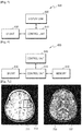
- FIG. 4 is a block diagram of the communication unit 132 according to an exemplary embodiment.
- the communication unit 132 of FIG. 4 may be connected to at least one of the gantry 20, the signal transceiver 30, the monitoring unit 40, the system control unit 50, and the operating unit 60 of FIG. 1 .
- the communication unit 132 may exchange data with a hospital server or other medical apparatuses in a hospital connected via a picture archiving and communication system (PACS), according to a digital imaging and communications in medicine (DICOM) standard.
- PACS picture archiving and communication system
- DICOM digital imaging and communications in medicine
- the communication unit 132 may communicate with the server 134, an external medical apparatus 136, or an external portable device 138 by being connected to a network 301 wirelessly or via wires.
- the communication unit 132 may transmit or receive data related to diagnosing an object, via the network 301, and may also transmit or receive a medical image captured by the external medical apparatus 136, such as a CT, an ultrasonic apparatus, or an X-ray apparatus.
- a medical image captured by the external medical apparatus 136 such as a CT, an ultrasonic apparatus, or an X-ray apparatus.
- the communication unit 132 of FIG. 4 may be included in the CT system 100 of FIG. 3 .
- the communication unit 132 of FIG. 4 and the communication unit 132 of FIG. 3 are the same.
- the communication unit 132 When the communication unit 132 is included in the CT system 100, the communication unit 132 may operate as follows.
- the communication unit 132 may be connected to the network 301 wirelessly or via wires and therefore may perform communication with the server 134, the external medical apparatus 136, or the external portable device 138.
- the communication unit 132 may exchange data with a hospital server or other medical apparatuses in a hospital connected via PACS.
- the communication unit 132 may also perform data communication with the external portable device 138 or the like, according to a DICOM standard.
- the communication unit 132 may transmit or receive data related to diagnosing the object 10, via the network 301.
- the communication unit 132 may also transmit or receive a medical image obtained from the external medical apparatus 136 such as an MRI apparatus, an X-ray apparatus, or the like.
- the communication unit 132 may also transmit information about a device error, information about a quality control status, or the like to a system manager or a service manager via the network 301, and may receive feedback corresponding to the information.
- the medical image providing apparatus may be included in a tomography system, such as the general MRI system or the CT system 100 described above with reference to FIGS. 1 through 4 .
- the medical image providing apparatus may be included in the server 134, the external medical apparatus 136, or the external portable device 138 connected to at least one tomography system, such as the MRI system of FIG. 1 and the CT system 100, via the network 301.
- the server 134, the external medical apparatus 136, or the external portable device 138 may be an image processing apparatus capable of displaying, storing, or processing at least one of an MRI image and a tomography image.
- the medical image providing apparatus may be in a form of the server 134, the external medical apparatus 136, or the external portable device 138, and may be a picture archiving and communication system (PACS) capable of displaying, storing, or processing at least one of an MRI image and a tomography image.
- PACS picture archiving and communication system
- the medical image providing apparatus may be included in any medical imaging system for reconstructing an image by using data obtained by scanning an object, aside from the MRI system or the CT system 100, or may be connected to any medical imaging system.
- FIG. 5 is a block diagram of a medical image providing apparatus 500 according to an exemplary embodiment.
- the medical image providing apparatus 500 may be included in the server 134, the external medical apparatus 136, or the external portable device 138 of FIG. 4 .
- the first list may include a list of images corresponding to a protocol applied while scanning the object.
- the UI unit 530 generates a UI screen including the first list and outputs the UI screen to the display unit 520. Then, the display unit 520 may display the UI screen. A user may see the first list displayed through the display unit 520 and select a predetermined protocol through the UI unit 530.
- the UI unit 530 may receive a predetermined request, a predetermined command, or other data from the user.
- the UI unit 530 may include an input device including a mouse, a keyboard, or hard keys for a data input.
- the user may select the first region in the first image by manipulating at least one of the mouse, the keyboard, or another input device included in the UI unit 530.
- the UI unit 530 may be a touch pad.
- the UI unit 530 may include a touch pad (not shown) combined to a display panel (not shown) included in the display unit 520, such that the UI screen is output on the display panel. Then, when a predetermined command is input through the UI screen, the touch pad detects the predetermined command to recognize the predetermined command input by the user.
- the UI unit 530 when the UI unit 530 is a touch pad and the user touches a predetermined point of the UI screen, the UI unit 530 detects the touched point. Then, the UI unit 530 may transmit information about the touched point to the control unit 510. The control unit 510 may recognize a request or command of the user corresponding to a menu option displayed on the touched point, and perform the recognized request or command.
- a first example of a method of imaging a medical image includes a method of photographing an object by irradiating a beam, such as an X-ray, on the object, like an imaging method of an X-ray image.
- the object is imaged regardless of a photographing technique or a scan mode.
- the method may image the object without having to perform a separate restoring or calculating operation to reconstruct an image.
- a second example includes a method of imaging an object by variously applying photographing techniques or scan modes while photographing the object, such as an MRI or CT image.
- images having different characteristics may be obtained even when the same region of a body is photographed, by using various variables considerable while scanning the object.
- an image suitable to a purpose may be obtained by changing a scan mode according to uses or purposes.
- the method may perform a separate restoring or calculating operation to reconstruct a target image.
- Image data may be obtained by applying a protocol may be used to generate a medical image that is a reconstructed image via image reconstruction.
- calculated or post-processed data or image may be generated by using image data obtained by applying a protocol.
- an object is scanned by applying various protocols, and an image of the object is reconstructed by using an MR signal obtained accordingly.
- data obtained by scanning the object for example, an MR signal or K-space data
- image data an image of the object, which is reconstructed by using image data
- a reconstructed image an image of the object, which is reconstructed by using image data
- the control unit 510 may control a second image reconstructed by using image data obtained by applying the first protocol to be overlaid and displayed on the first region of the first image.
- a plurality of partial regions may be selected from the first image.
- a predetermined protocol may be individually selected for the partial regions.
- the control unit 510 may overlay and display reconstructed images corresponding to the individual protocols selected for the partial regions, on the first region of the first image.
- FIG. 6 is a block diagram of a medical image providing apparatus 600 according to another exemplary embodiment.
- the medical image providing apparatus 600 of FIG. 6 further includes a memory 640, compared to the medical image providing apparatus 500.
- a control unit 610, a display unit 620, and a UI unit 630 of the medical image providing apparatus 600 respectively correspond to the control unit 510, the display unit 520, and the UI unit 530 of the medical image providing apparatus 500. Accordingly, descriptions about the medical image providing apparatus 600 that are the same as those of the medical image providing apparatus 500 of FIG. 5 are not repeated.
- images reconstructed by using image data obtained by applying different protocols differently express an object and have different image characteristics.
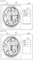
- FIG. 8A is a diagram for describing operations of the medical image providing apparatus 600, according to an exemplary embodiment.
- the UI unit 630 When a first region 820 in the first image 810 is selected, the UI unit 630 outputs a first list including at least one protocol applied while scanning an object.
- the first list may include at least one item corresponding to at least one of the plurality of MRI protocols and the plurality of CT protocols described above.
- one region i.e., the first region 820, is selected, but alternatively, a plurality of partial regions may be selected from the first image 810.
- the UI unit 630 may receive a selection on a region of interest (ROI) in the first image 810 from a user. For example, when the user selects a predetermined region by using a mouse, the UI unit 630 may set the selected predetermined region as an ROI.
- the ROI is the first region 820.
- One ROI is set in FIG. 8A , but alternatively, a plurality of ROIs may be set.
- an ROI having a predetermined size around the predetermined point may be automatically set.
- the UI unit 630 includes a mouse and the user clicks a predetermined point on the first image 810, a rectangular ROI having a predetermined size around the predetermined point may be set.
- a size of an ROI may be pre-set by the user or may be set by the control unit 610.
- a rectangular ROI having a predetermined size around the touched predetermined point may be set.
- the user may adjust a size of an ROI through the UI unit 630 to set the first region 820.
- the UI unit 630 includes a mouse and the user clicks a predetermined point on the first image 810, a quadrangle for setting the first image 810 may be displayed and the user may adjust a size of the displayed quadrangle to adjust the size of the first region 820.
- the user may adjust at least one of the size, location, and shape of the first region 820 by using any one of various input devices in the UI unit 630.
- the first region 820 may be automatically selected by the control unit 610, without having to be selected by the user. In other words, the control unit 610 may automatically select or extract the first region 820 from the first image 810.
- control unit 610 may generate a second image corresponding to the first region 820 in real-time by using the stored reconstructed image.
- control unit 610 may obtain image data in real-time by operating a medical image system, such as an MRI system, for capturing a medical image by applying the predetermined protocol. Then, the control unit 610 may reconstruct a second image by using the obtained image data.
- a medical image system such as an MRI system
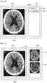
- FIG. 8B is a diagram for describing operations of a medical image providing apparatus, according to an exemplary embodiment.
- the first image 810 included in the screen 800 displayed by the display unit 620 is an MRI image
- a first image 870 included in a screen 860 displayed by the display unit 620 is a CT image.
- the first image 870 is an anatomical image of a brain CT image to represent anatomical structure of a brain.
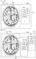
- FIGS. 9A and 9B show diagrams for describing operations of the medical image providing apparatus 600, according to another exemplary embodiment.
- FIG. 9A illustrates an example of a first list 910 output on the display unit 620.
- FIG. 9B illustrates another example of a first list 955 output on the display unit 620.
- a screen 900 displayed on the display unit 620 includes the first image 810 and the first list 910.
- the medical image providing apparatus 600 may automatically output the first list 910 including at least one protocol.
- the first list 910 may include at least one protocol described above.
- the first list 910 includes at least one protocol applied while scanning an object.
- the at least one protocol is used to obtain images of the same body region having different characteristics, and as described above, may include at least one of MRI protocols and CT protocols.
- the first list 910 may also include image lists according to protocols applied while scanning an object.
- a 'T1W' item in the first list 910 may denote a 'T1W protocol' or a 'T1-weighted image' scanned and reconstructed by applying the 'T1W protocol'.
- protocols it is assumed that items in a first list denote protocols.
- the user may select a predetermined protocol in the first list 910. For example, the user may select the T1W protocol through the UI unit 630.
- the second image displayed on the first region 820 may be a partial image corresponding to a predetermined region of the object included in the first region 820 with respect to an image obtained by applying a selected protocol.
- control unit 610 overlays and displays on the first region 820 of the first image 810, a region 711 of FIG. 7 of the T1-weighted image 710, which equally corresponds to the first region 820.
- the user may select a T1W protocol for generating a T1-weighted image that satisfactorily shows an anatomical structure, through the UI unit 630. Then, the control unit 610 overlays and displays on the first region 820, the T1-weighted image reconstructed by using image data obtained by the T1W protocol.
- the user may select a T2W protocol for generating a T2-weighted image that satisfactorily shows a tumor, through the UI unit 630. Then, the control unit 510 overlays and displays on the first region 820, a T2-weighted image reconstructed by using image data obtained by the T2W protocol.
- a screen 950 displayed on the display unit 620 may include the first image 810 and the first list 955.
- the medical image providing apparatus 600 may output the first list 955 including at least one protocol.
- the first list 955 may include at least one protocol described above.
- a plurality of protocols are used to obtain images of the same body region having different characteristics, and as described above, may include at least one of MRI protocols and CT protocols.
- the first list 955 includes a T1W protocol, a T2W protocol, a diffusion protocol, and a perfusion protocol, which are MRI protocols 960, and a perfusion protocol that is a CT protocol 970. Also, the first list 955 may separately include the MRI protocol 960 and the CT protocol 970, as shown in FIG. 9B .
- a protocol may be selected by considering a detailed region of an object to be diagnosed, and a disease to be diagnosed in the detailed region.
- the medical image providing apparatuses 500 and 600 output a list of protocols, and overlay and display an image of a predetermined protocol in an ROI to output a medical image suitable to an intention of the user.
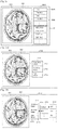
- FIGs. 10A and 10B show diagrams for describing operations of the medical image providing apparatus 600, according to another exemplary embodiment.
- a screen 1000 displayed on the display unit 620 may include the first image 810 and a first list 1010.
- the medical image providing apparatus 600 may output the first list 1010.
- the first list 1010 may include at least one protocol described above, and at least one manipulation menu item.
- the first list 1010 may include a first sub-list 1020 including at least one protocol, and a second sub-list 1030 including at least one manipulation menu item.
- a manipulation menu item is a menu option for manipulating characteristics of an image included in the first region 820 of the first image 810.
- Examples of the manipulation menu item include a menu option for filtering an image of the first region 820 by using a predetermined filter, a menu option for adjusting a window level (WL) of the image of the first region 820, and a menu option for adjusting a contrast of the image of the first region 820.
- WL window level
- the second sub-list 1030 including the at least one manipulation menu item includes a first filter (filter 1), a second filter (filter 2), and a WL adjusting item (WL adjustment).
- control unit 510 may filter an image of the first region 820 by using the filter 1, and overlay and display the filtered image on the first region 820.
- control unit 510 may adjust a WL of the image of the first region 820, and overlay and display the adjusted image on the first region 820.
- the at least one protocol and the at least one manipulation menu item included in the first list 1010 may be included in one list.
- the first sub-list 1020 including the at least one protocol and the second sub-list 1030 including the at least one manipulation menu item may be separately included in the first list 1010.
- an image corresponding to a protocol included in the first item may be changed according to a manipulation menu option included in the second item. Then, the changed image may be displayed on the first region 820.
- the first sub-list 1053 includes at least one of a plurality of MRI protocols 1061 and manipulation menu items 1062 of an MRI image.
- the UI unit 630 may output the manipulation menu item 1120 depending on the T2W protocol item.
- a screen 1200 displayed on the display unit 620 may include the first image 810 and a first list 1210.
- the medical image providing apparatus 600 may output the first list 1210.
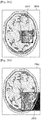
- the screen 1360 displayed by the display unit 620 may include the first image 810 and the first list 1310.
- the medical image providing apparatus 600 may output the first list 1310.
- a predetermined protocol is activated from the first list 1310
- a sub-list 1370 including at least one image reconstructed, processed, or calculated by using image data obtained by applying the selected predetermined protocol may be output.
- a protocol included in the predetermined item is activated.
- the sub-list 1370 including at least one image corresponding to the activated protocol included in the predetermined item is output.
- the control unit 610 may control the sub-list 1370 including a CBV map 1371, a CBF map 1372, an MTT map 1373, which are calculated by using image data obtained by scanning an object by applying the perfusion protocol, to be displayed.
- the control unit 610 may overlay and display a partial region included in the first region 820 of the CBV map on the first region 820 of the first image 810.
- FIG. 14 is a diagram for describing operations of the medical image providing apparatus 600, according to another exemplary embodiment.
- a screen 1400 displayed on the display unit 620 may include the first image 810 and a first list 1410.
- the medical image providing apparatus 600 may output the first list 141.
- the UI unit 630 may output the sub-list 1520 including a '01 December 2013' item and a '01 December 2013' item, which are points of time when the image data corresponding to the T2W protocol items are obtained.
- the control unit 610 may overlay and display a T2-weighted image reconstructed by using the image data obtained on 01 December 2012, on the first region 820.
- each item of the sub-list 1520 may include a reconstructed image obtained at a point of time displayed on each item.
- a reconstructed image included in each item of the sub-list 1520 may be a whole image of an object or a partial image corresponding to the first region 820.
- FIG. 16 is a diagram for describing operations of the medical image providing apparatus 600, according to another exemplary embodiment.
- a screen 1600 displayed on the display unit 620 may include the first image 810 and a first list 1610.
- the medical image providing apparatus 600 may output the first list 1610.
- the first list 1610 may include at least one item indicating a point of time when image data or reconstructed image obtained by applying at least one protocol is obtained.
- at least one point of time item included in the first list 1610 is related to a medical image of the same patient and the same region.
- a first item 1611 in the first list 1610 is related to a medical image captured on 01 December 2012
- a second item 1612 is related to a medical image captured on 01 December 2013.
- the second item 1612 when the second item 1612 is selected through the UI unit 630, the second item 1612 may include a sub-list 1620 including image data or a reconstructed image obtained by applying a predetermined protocol on 01 December 2013.
- the control unit 610 overlays and displays a T2-weighted image on the first region 820 photographed on 01 December 2013.
- the control unit 610 may read information about a photographing point of time and a protocol from the memory 640. Then, the UI unit 630 may output the first list 1610 and the sub-list 1620, as shown in FIG. 16 , by using the information read by the control unit 610.
- FIG. 17 is a diagram for describing operations of the medical image providing apparatus 600, according to another exemplary embodiment.
- a screen 1700 displayed on the display unit 620 may include the first image 810 and a second list 1710.
- the medical image providing apparatus 600 may output the second list 1710.
- the UI unit 630 may output the second list 1710 including at least one reconstructed image corresponding to a protocol.
- a list including a reconstructed image according to at least one protocol will be referred to as the second list 1710.
- the UI unit 630 may receive a selection on a predetermined reconstructed image included in the second list 1710. It is assumed that the selected predetermined reconstructed image is a first reconstructed image. Then, the control unit 610 may overlay and display a second image on the first region 820 of the first image 810, by using the first reconstructed image.
- the second image overlaid on the first region 820 is an image included in an area corresponding to a predetermined region of an object included in the first region 820, with respect to the first reconstructed image.
- reconstructed images 1720 and 1730 included in the second list 1710 may be partial images corresponding to the first region 820.
- the reconstructed images 1720 and 1730 may equally correspond to the regions 711 and 721 described above with reference to FIG. 7A , respectively.
- the selected reconstructed image 1720 or 1730 is overlaid and displayed on the first region 820.
- the user may select a first reconstructed image by clicking and dragging any one of the reconstructed images 1720 and 1730 included in the second list 1710.
- the user may select a first reconstructed image by doubling clicking any one of the reconstructed images 1720 and 1730.
- a method of selecting one of the reconstructed images 1720 and 1730 may differ based on an input device included in the UI unit 630, examples of the input device including a keyboard, a mouse, and a touch pad.
- the first region 820 that is one partial region is selected, but alternatively, a plurality of partial regions may be selected from the first image 810. In this case, a reconstructed image to be overlaid may be individually selected according to the selected plurality of partial regions.
- the second list 1710 may include at least one manipulation menu item (not shown) for manipulating at least one reconstructed image or the first region 820 of the first image 810. Since the manipulation menu item has been described above with reference to FIG. 10A , details thereof are not repeated here.
- the second list 1710 may include at least one additional image (not shown) generated by using at least one piece of image data obtained by applying at least one protocol.
- the additional image is information obtained by using image data obtained by applying a protocol as described above, and may be a CBV map, a CBF map, or a histogram equalization image.
- the additional image that may be included in the second list 1710 equally corresponds to an image corresponding to the additional item described with reference to FIG. 12 .
- the second list 1810 may include at least one reconstructed image corresponding to a protocol.
- the reconstructed image included in the second list 1810 may be a whole image of an object.
- a reconstructed image 1820 and a reconstructed image 1830 included in the second list 1810 may equally correspond to the T1-weighted image 710 and the T2-weighted image 720 of FIG. 7A , respectively.
- a screen 1850 shows a reconstructed image included in the second list 1810 may be a whole image of an object, and a region corresponding to the first region 820 may be displayed on reconstructed images, i.e., the T1 and T2-weighted images 710 and 720, included in the second list 1810.
- a region 1860 corresponding to the first region 820 may be displayed in the T1-weighted image 710, and a region 1870 corresponding to the first region 820 may be displayed in the T2-weighted image 720.
- FIG. 19 is a diagram for describing operations of the medical image providing apparatus 600, according to another exemplary embodiment.
- a screen 1900 displayed on the display unit 620 may include the first image 810 and a second list 1910.
- the medical image providing apparatus 600 may output the second list 1910.
- each of items 1920 and 1930 may include a reconstructed image 1921 according to protocols, and information 1922 about the reconstructed image 1921.
- the information 1922 may include a protocol of the reconstructed image 1921.
- the information 1922 may further include at least one of a point of time when the reconstructed image 1920 is obtained, and a disease history of a patient.
- the reconstructed image 1921 may be a whole image or partial image of an object.
- FIG. 20 is a diagram for describing operations of the medical image providing apparatus 600, according to another exemplary embodiment.
- a screen 2000 displayed on the display unit 620 may include the first image 810 and a second list 2010.
- the medical image providing apparatus 600 may output the second list 2010.
- the UI unit 630 may generate at least one manipulation menu item for manipulating each of at least one reconstructed image, and may add the generated at least one manipulation menu item to each of the at least one reconstructed image included in the second list 2010.
- each item, for example, a first item 2020, included in the second list 2010 may include a reconstructed image 2012 and a manipulation menu item 2022.
- control unit 610 may filter the reconstructed image 2012 by using the filter 1, and overlay and display the filtered reconstructed image 2012 on the first region 820.
- FIG. 21 is a diagram for describing operations of the medical image providing apparatus 600, according to another exemplary embodiment.
- a screen 2100 displayed on the display unit 620 may include the first image 810 and a second list 2110.
- the medical image providing apparatus 600 may output the second list 2110.
- each item of the second list 2110 may include at least one reconstructed image according to points of time corresponding to a protocol.
- a 'reconstructed image according to points of time' denotes a medical image captured and reconstructed at a predetermined point of time.
- the T1-weighted image 2121 captured on 01 December 2012 is overlaid and displayed on the first region 820.
- a screen 2200 displayed on the display unit 620 may include the first image 810 and a second list 2210.
- the medical image providing apparatus 600 may output the second list 2210.
- an image included in the second list 2210 may be a partial image indicating a region of an object included in the first region 820, or an image indicating the object corresponding to the first image 810.
- the second list 2210 includes the partial image.
- control unit 610 may display a preview menu of a reconstructed image corresponding to a predetermined item included in a first list that is focused by using an input device included in the UI unit 630.
- FIG. 23 is a diagram for describing operations of the medical image providing apparatus 600, according to another exemplary embodiment.
- a screen 2300 displayed on the display unit 620 includes the first image 810 and a first list 2310.
- the medical image providing apparatus 600 may output the first list 2310 including at least one protocol.
- the user may focus a predetermined item of the first list 2310 by using an input device included in the UI unit 630.
- the input device is a mouse, a keyboard, or a touch pad
- the user may select the predetermined item by using a cursor 2311 corresponding to manipulation of the input device.
- the user may locate the cursor 2311 on the predetermined item, and select the predetermined item through the input device. For example, when the user selects the predetermined item by using a mouse, the user may move the cursor 2311 to a desired location and then double-click the mouse so as to select a 'T2W protocol' item where the cursor 2311 is located.
- a reconstructed image corresponding to a protocol focused by the user may be displayed even before the first region 820 is selected.
- a reconstructed image corresponding to the predetermined item may be overlaid and displayed on the first region 820 even before the user selects the predetermined item by determining that the predetermined item where the cursor 2311 is located is activated.
- a reconstructed image overlaid on the first region 820 may correspondingly change.
- the user may pre-view an image corresponding to a protocol corresponding to a predetermined item on the first region 820 by locating the cursor 2311 on the predetermined item, and finally select or not select the predetermined item.
- FIGs. 24A and 24B show diagrams for describing operations of the medical image providing apparatus 600, according to another exemplary embodiment.
- a screen 2400 displayed on the display unit 620 includes the first image 810 and a first list 2410.
- the medical image providing apparatus 600 may output the first list 2410 including at least one protocol.
- the control unit 610 may display a reconstructed image 2420 corresponding to the focused predetermined item.
- the reconstructed image 2420 may be an image corresponding to the first image 810 or a partial image corresponding to the first region 820.
- the reconstructed image 2420 is the image corresponding to the first image 810.
- the control unit 610 may perform a preview function by displaying a reconstructed image corresponding to the predetermined item where the cursor is located, on the screen 2400.
- a reconstructed image displayed on the screen 2400 may be changed accordingly. Accordingly, in FIG. 24A , the reconstructed image 2420 that is a T2-weighted image corresponding to a 'T2W protocol' where a cursor 2411 is located may be displayed on the screen 2400.
- the reconstructed image 2420 may be a whole image corresponding to a predetermined protocol, and a region 2430 corresponding to the first region 820 may be displayed.
- the control unit 610 may display a reconstructed image 2470 corresponding to the focused predetermined item. Accordingly, the reconstructed image 2470 that is a T2-weighted image corresponding to a 'T2W protocol' where a cursor 2461 is located may be displayed on a screen 2450.
- the reconstructed image 2470 is reconstructed by applying the T2W protocol, and may include a region corresponding to the first region 820.
- a plurality of partial regions may be selected from the first image 810 via a user's setting or automatic extraction.
- the plurality of partial regions may be sequentially highlighted.
- a T1W protocol is selected as denoted by a reference numeral 2511 correspondingly to the first region 2520 on the left
- a T2W protocol is selected as denoted by a reference numeral 2513 correspondingly to the first region 820 on the right.
- protocols selected correspondingly to a plurality of partial regions may be displayed as shown in regions 2530 so that the user easily recognizes the selected protocols. After the protocols are selected as such, images according to the protocols corresponding to the plurality of partial regions may be overlaid and displayed on the plurality of partial regions.
- the screen 2550 may include the first list 2570 for selecting the protocol corresponding to the first region 2520 on the left, and the first list 2560 for selecting the protocol corresponding to the first region 820 on the right.
- a T1W protocol is selected as denoted by a reference numeral 2571 correspondingly to the first region 2520 on the left
- a T2W protocol is selected as denoted by a reference numeral 2561 correspondingly to the first region 820 on the right.
- FIG. 26 is a diagram for describing operations of the medical image providing apparatus 600, according to another exemplary embodiment.
- a screen 2600 displayed on the display unit 620 may include the first image 810 and a first list 2610.
- the medical image providing apparatus 600 may output the first list 2610.
- the first list 2610 may include at least one of anatomical image items corresponding to protocols and functional image items corresponding to protocols.
- Images corresponding to protocols described above may be classified into anatomical images and functional images.
- the medical image providing apparatus 600 may output the first list 2710.
- the first list 2710 includes an anatomical image item 2711 corresponding to a protocol, and a functional image item 2712 corresponding to a protocol.
- the first list 2710 may further include a past medical image item 2713 of the same patient.
- FIGs. 28A, 28B and 28C show diagrams for describing operations of the medical image providing apparatus 600, according to another exemplary embodiment.
- the range of the object included in a second image 2860 may be expanded. Accordingly, a screen 2850 of FIG. 28B may be displayed to the user.
- a second image 2890 obtained by expanding a second image that was overlaid on the first region 2810 may be displayed. Accordingly, a screen 2880 of FIG. 28C may be displayed to the user.
- the control unit 610 may switch and display a first region 2910 and a first image 2900, according to a user's request input through the UI unit 630.
- an image type of an image displayed in the first region 2910 and an image type of the first image 2900 displayed throughout a screen may be mutually switched.
- a T2W protocol is selected from a first list, and a T2-weighted image may be overlaid and displayed on the first region 2910.
- the first image 2900 is an MRI scout image.
- a first image 2950 that is a whole image is switched from an MRI scout image to a T2-weighted image
- a first image 2960 that is a partial image is switched from a T2-weighted image to an MRI scout image.
- the UI unit 630 may output a menu including an 'image type changing key' (not shown).
- an image type may be changed when the user touches or clicks the first image 2900 a predetermined number of times.
- FIGS. 30A and 30B show diagrams for describing operations of the medical image providing apparatus 600, according to another exemplary embodiment.
- a screen 3000 displayed on the display unit 620 may include the first image 810, a first list 3010, and a second list 3020.
- the first list 3010 is used to select a protocol of an image to be displayed on the first region 820.
- the second list 3020 is used to select a protocol of an image to be displayed on the first image 810 but not on the first region 820.
- the first region 820 when the first region 820 is set as an ROI, protocols corresponding to the inside and outside of the ROI may be individually set.
- a protocol of an image to be overlaid on the first region 820 is selected to be a T2W protocol from a first list 3060, and a protocol of the first image 810 but not on the first region 820 is selected to be a T1W protocol from a second list 3070. Accordingly, a T2-weighted image is displayed on the first region 820 and a T1-weighted image is displayed on the first image 810 but not on the first region 820.
- FIGS. 31A and 31B show diagrams for describing operations of the medical image providing apparatus 600, according to another exemplary embodiment.
- a protocol may be first selected before a first region is selected, and then the first region may be set after the protocol is selected.
- the display unit 620 may display a screen 3100 including a first list 3120.
- the user may select a predetermined item included in the first list 3120 by using a cursor 3130.
- the first list 3120 may have any one of various shapes shown in FIGS. 9 through 30 , as well as a shape shown in FIGs. 31A and 31B .
- the first list 3120 may include at least one of a plurality of anatomical image items corresponding to a protocol and a plurality of functional image items corresponding to a protocol.
- control unit 610 may then set a first region 3150.
- a screen 3200 showing that a T2W protocol is selected first, and then a first region 3210 corresponding to the T2W protocol is set. Then, a T1W protocol is selected, and a first region 3220 corresponding to the T1W protocol is set.
- FIG. 33 is a diagram for describing operations of the medical image providing apparatus 600, according to another exemplary embodiment.
- control unit 610 may generate a CBV map or CBF map corresponding to a perfusion protocol so as to further accurately read the blood vessels or blood flow.
- the generated CBV map or CBF map may be overlaid and displayed on the first region 3310.
- the memory 640 may include at least one piece of image data corresponding to at least one protocol.
- the control unit 610 may read image data for accurately reading the disease or disorder from the memory 640 and reconstruct a second image.
- the memory 640 may store at least one reconstructed image reconstructed by using at least one piece of image data corresponding to at least one protocol.
- the control unit 610 may read a reconstructed image for accurately reading the disease or disorder from the memory 640, and overlay and display the reconstructed image on the first region 3310.
- FIGS. 34A and 34B show diagrams for describing operations of the medical image providing apparatus 600, according to another exemplary embodiment.
- the medical image providing apparatus 600 may automatically output the first list 3510.
- the first list 3510 includes image items obtained by using the first image 810.
- the first image 810 is an image reconstructed by using image data obtained by applying a predetermined protocol
- an image that is reconstructed, calculated, or post-processed by using the image data may be included in the first list 3510.
- a first list 3560 displayed on a screen 3550 may include an MTT map item, a CBF map item, and a CBV map item.
- FIG. 36 illustrates a screen 3600 output by the display unit 620.
- a first image 3610 included in the screen 3600 is a CT image
- a first list 3630 includes CT protocols.
- the first list 3630 may include protocols applied to CT scan, such as a CT perfusion protocol 3631 and a CT angiography protocol 3632 indicating a 'DSA protocol'.
- the control unit 610 may control an image obtained according to a perfusion protocol to be overlaid and displayed on a first region 3620.
- FIG. 37 shows a diagram for describing operations of the medical image providing apparatus 600, according to another exemplary embodiment.
- FIG. 37 illustrates a screen 3700 output by the display unit 620. Since the screen 3700 of FIG. 37 is the same as the screen 3600 of FIG. 36 except for a second list 3730 including at least one image obtained based on image data obtained by applying at least one protocol, descriptions thereof that are the same as those of the screen 3600 of FIG. 36 are not provided here.
- the second list 3730 includes at least one image obtained based on image data obtained by applying CT protocols.
- the at least one image included in the second list 3730 may be an image of an object or a partial image indicating a region of the object.
- the second list 3730 includes the image of the object.
- a selection of a first protocol included in the first list is received through a UI in operation 3830.
- Operation 3830 may be performed by the UI unit 630 under control of the control unit 610.
- a first image including an object is displayed in operation 3910.
- Operation 3910 may be performed by the display unit 620 under control of the control unit 610.
- a first list including at least one reconstructed image that is reconstructed by using at least one piece of image data obtained by applying at least one protocol applied while scanning the object is output in operation 3920.
- Operation 3920 may be performed by the UI unit 630 under control of the control unit 610.
- FIG. 40 is a flowchart of a medical image processing method 4000 according to another exemplary embodiment.
- the medical image processing method 4000 according to an exemplary embodiment may be performed by the medical image providing apparatus 500 or 600 described above with reference to FIGS. 1 through 37 . Also, since operations of the medical image processing method 4000 include the same features as operations of the medical image providing apparatus 500 or 600, descriptions thereof that are the same as those of FIGS. 1 through 37 are not provided again.
- a selection of a first region of the first image is received through a UI in operation 4020.
- Operation 4020 may be performed by the UI unit 630 under control of the control unit 610.
- FIG. 41 is a flowchart of a medical image processing method 4100 according to another exemplary embodiment.
- the medical image processing method 4100 according to an exemplary embodiment may be performed by the medical image providing apparatus 500 or 600 described above with reference to FIGS. 1 through 37 .
- operations of the medical image processing method 4100 include the same features as operations of the medical image providing apparatus 500 or 600, descriptions thereof that are the same as those of the medical image providing apparatus 500 or 600 of FIGS. 1 through 37 are not provided again.
- a selection of a first protocol from the first list is received through a UI in operation 4120.
- Operation 4120 may be performed by the UI unit 630 under control of the control unit 610.
- a first region is set in the first image including the object in operation 4130.
- Operation 4130 may be performed by the control unit 610.
- operation 4130 may be performed by the UI unit 630 under control of the control unit 610.
- a second image reconstructed by using image data obtained by applying the first protocol is overlaid and displayed on the first region in operation 4140.
- Operation 4140 may be performed by the display unit 620 under control of the control unit 610.
- FIG. 42 is a flowchart of a medical image processing method 4200 according to another exemplary embodiment.
- the medical image processing method 4200 according to an exemplary embodiment may be performed by the medical image providing apparatus 500 or 600 described above with reference to FIGS. 1 through 37 .
- operations of the medical image processing method 4200 include the same features as operations of the medical image providing apparatus 500 or 600, descriptions thereof that are the same as those of the medical image providing apparatus 500 or 600 of FIGS. 1 through 37 are not provided again.
- a first image including an object is displayed in operation 4210.
- Operation 4210 may be performed by the display unit 620 under control of the control unit 610.
- a selection of a predetermined item included in the first list is received through a UI in operation 4220.
- Operation 4220 may be performed by the UI unit 630 under control of the control unit 610.
- a selection of a first region from the first image is received through a UI in operation 4230.
- Operation 4220 may be performed by the UI unit 630 under control of the control unit 610.
- a second image corresponding to the predetermined item selected in operation 4220 is overlaid and displayed on the first region in operation 4240.
- Operation 4240 may be performed by the display unit 620 under control of the control unit 610.
- a medical image providing apparatus and a medical image processing method of the same may provide a UI screen for a user, such as a doctor, to easily read a medical image of a patient.
- the user may further easily diagnose a disease and read the medical image.
- Examples of the computer-readable recording medium include magnetic storage media (e.g., ROM, floppy disks, hard disks, etc.), optical recording media (e.g., CD-ROMs or DVDs), etc.
- magnetic storage media e.g., ROM, floppy disks, hard disks, etc.
- optical recording media e.g., CD-ROMs or DVDs
Applications Claiming Priority (4)
| Application Number | Priority Date | Filing Date | Title |
|---|---|---|---|
| KR20140005206 | 2014-01-15 | ||
| KR1020140156244A KR101604812B1 (ko) | 2014-01-15 | 2014-11-11 | 의료 영상 처리 장치 및 그에 따른 의료 영상 처리 방법 |
| PCT/KR2015/000273 WO2015108306A1 (fr) | 2014-01-15 | 2015-01-12 | Appareil producteur d'images médicales et son procédé de traitement d'images médicales |
| EP15737905.8A EP2941187A4 (fr) | 2014-01-15 | 2015-01-12 | Appareil producteur d'images médicales et son procédé de traitement d'images médicales |
Related Parent Applications (1)
| Application Number | Title | Priority Date | Filing Date |
|---|---|---|---|
| EP15737905.8A Division EP2941187A4 (fr) | 2014-01-15 | 2015-01-12 | Appareil producteur d'images médicales et son procédé de traitement d'images médicales |
Publications (2)
| Publication Number | Publication Date |
|---|---|
| EP3545837A1 true EP3545837A1 (fr) | 2019-10-02 |
| EP3545837B1 EP3545837B1 (fr) | 2021-12-29 |
Family
ID=53521393
Family Applications (4)
| Application Number | Title | Priority Date | Filing Date |
|---|---|---|---|
| EP15737905.8A Ceased EP2941187A4 (fr) | 2014-01-15 | 2015-01-12 | Appareil producteur d'images médicales et son procédé de traitement d'images médicales |
| EP21206536.1A Pending EP3995075A1 (fr) | 2014-01-15 | 2015-01-12 | Appareil de fourniture d'images médicales et son procédé de traitement d'images médicales |
| EP19173691.7A Active EP3545837B1 (fr) | 2014-01-15 | 2015-01-12 | Appareil de fourniture d'images médicales et son procédé de traitement d'images médicales |
| EP15188808.8A Active EP2992828B1 (fr) | 2014-01-15 | 2015-01-12 | Appareil de fourniture d'image médicale et procédé de traitement d'image médicale de celui-ci |
Family Applications Before (2)
| Application Number | Title | Priority Date | Filing Date |
|---|---|---|---|
| EP15737905.8A Ceased EP2941187A4 (fr) | 2014-01-15 | 2015-01-12 | Appareil producteur d'images médicales et son procédé de traitement d'images médicales |
| EP21206536.1A Pending EP3995075A1 (fr) | 2014-01-15 | 2015-01-12 | Appareil de fourniture d'images médicales et son procédé de traitement d'images médicales |
Family Applications After (1)
| Application Number | Title | Priority Date | Filing Date |
|---|---|---|---|
| EP15188808.8A Active EP2992828B1 (fr) | 2014-01-15 | 2015-01-12 | Appareil de fourniture d'image médicale et procédé de traitement d'image médicale de celui-ci |
Country Status (6)
| Country | Link |
|---|---|
| US (4) | US9582152B2 (fr) |
| EP (4) | EP2941187A4 (fr) |
| KR (1) | KR101604812B1 (fr) |
| CN (3) | CN108324310B (fr) |
| IN (1) | IN2015MN02211A (fr) |
| WO (1) | WO2015108306A1 (fr) |
Families Citing this family (56)
| Publication number | Priority date | Publication date | Assignee | Title |
|---|---|---|---|---|
| WO2015059613A2 (fr) * | 2013-10-22 | 2015-04-30 | Koninklijke Philips N.V. | Visualisation d'images |
| KR101604812B1 (ko) | 2014-01-15 | 2016-03-18 | 삼성전자주식회사 | 의료 영상 처리 장치 및 그에 따른 의료 영상 처리 방법 |
| KR101659577B1 (ko) * | 2014-08-14 | 2016-09-23 | 삼성전자주식회사 | 자기 공명 영상 장치 및 자기 공명 영상의 생성 방법 |
| JP6489819B2 (ja) * | 2014-12-15 | 2019-03-27 | キヤノン株式会社 | 制御装置、制御システム、x線撮影システム、制御システム、制御方法、及びプログラム |
| JP6624784B2 (ja) * | 2015-01-06 | 2019-12-25 | キヤノン株式会社 | 放射線撮影システム及びその制御方法、情報処理装置及びその制御方法、コンピュータプログラム |
| JP6072097B2 (ja) * | 2015-01-30 | 2017-02-01 | キヤノン株式会社 | 放射線撮影装置、制御装置、長尺撮影システム、制御方法、及びプログラム |
| JP6517031B2 (ja) * | 2015-02-05 | 2019-05-22 | キヤノンメディカルシステムズ株式会社 | 医用画像処理装置および磁気共鳴イメージング装置 |
| DE102015208202B3 (de) * | 2015-05-04 | 2016-09-22 | Bayer Pharma Aktiengesellschaft | Verfahren zum automatischen Ermitteln eines Kontrastmittelprotokolls sowie Bildgebungsverfahren, Kontrastmittelprotokoll-Ermittlungseinrichtung, bildgebende medizinische Einrichtung, Computerprogrammprodukt und computerlesbares Medium |
| BR112018002613A2 (pt) * | 2015-08-07 | 2019-02-05 | Shanghai United Imaging Healthcare Co Ltd | sistema e método de imagem de multi-modalidade |
| US10383590B2 (en) * | 2015-09-28 | 2019-08-20 | General Electric Company | Methods and systems for adaptive scan control |
| KR101806841B1 (ko) * | 2015-10-26 | 2017-12-11 | 주식회사 인피니트헬스케어 | 영상 기반 뇌졸중 병변 진단 시스템 및 방법 |
| KR20170064297A (ko) * | 2015-12-01 | 2017-06-09 | 삼성전자주식회사 | 의료 영상 장치 및 그 제어 방법 |
| DE102016202663A1 (de) * | 2016-02-22 | 2017-08-24 | Siemens Healthcare Gmbh | MRT-Vorschau |
| US9786069B2 (en) * | 2016-03-07 | 2017-10-10 | Siemens Healthcare Gmbh | Refined reconstruction of time-varying data |
| US10444308B2 (en) * | 2016-05-31 | 2019-10-15 | Canon Medical Systems Corporation | Magnetic resonance imaging apparatus |
| CN106095254B (zh) * | 2016-06-14 | 2019-11-19 | 上海联影医疗科技有限公司 | 一种医学图像的用户标记显示方法和用户显示界面 |
| JPWO2018003939A1 (ja) * | 2016-06-30 | 2019-06-27 | アイキューブド研究所株式会社 | 画像出力装置、画像出力方法、およびプログラム |
| KR101821353B1 (ko) * | 2016-08-30 | 2018-01-23 | 삼성전자주식회사 | 자기 공명 영상 장치 |
| DE102016218356A1 (de) * | 2016-09-23 | 2018-03-29 | Siemens Healthcare Gmbh | Verfahren zum Betrieb einer Magnetresonanzanlage, Datenträger sowie Magnetresonanzanlage |
| JP6780484B2 (ja) * | 2016-12-13 | 2020-11-04 | カシオ計算機株式会社 | 情報処理装置及びプログラム |
| US10504621B2 (en) * | 2016-12-28 | 2019-12-10 | Canon Medical Systems Corporation | Medical image processing apparatus, medical imaging apparatus and image archiving apparatus |
| JP7062360B2 (ja) * | 2016-12-28 | 2022-05-06 | キヤノン株式会社 | 情報処理装置、情報処理装置の作動方法およびプログラム |
| CN108403117B (zh) * | 2017-02-10 | 2021-10-29 | 西门子(深圳)磁共振有限公司 | 磁共振成像预览及建立mr模型的方法和装置 |
| US10416321B2 (en) * | 2017-03-15 | 2019-09-17 | Canon Medical Systems Corporation | X-ray diagnostic apparatus |
| KR101883806B1 (ko) | 2017-04-07 | 2018-07-31 | 울산과학기술원 | 영상 복원 장치 및 방법 |
| DE102017003517A1 (de) * | 2017-04-11 | 2018-10-11 | Universität Hamburg | Verfahren und Messvorrichtung zur Röntgenfluoreszenz-Messung |
| JP6877298B2 (ja) * | 2017-08-29 | 2021-05-26 | ゼネラル・エレクトリック・カンパニイ | 医用画像装置 |
| CN107689030A (zh) * | 2017-09-18 | 2018-02-13 | 上海联影医疗科技有限公司 | 一种图像处理的方法及装置 |
| US11723579B2 (en) | 2017-09-19 | 2023-08-15 | Neuroenhancement Lab, LLC | Method and apparatus for neuroenhancement |
| KR20190058952A (ko) * | 2017-11-22 | 2019-05-30 | 삼성전자주식회사 | 자기 공명 영상 장치 및 그 제어방법 |
| US11717686B2 (en) | 2017-12-04 | 2023-08-08 | Neuroenhancement Lab, LLC | Method and apparatus for neuroenhancement to facilitate learning and performance |
| US11273283B2 (en) | 2017-12-31 | 2022-03-15 | Neuroenhancement Lab, LLC | Method and apparatus for neuroenhancement to enhance emotional response |
| CN108324312A (zh) * | 2018-01-19 | 2018-07-27 | 上海联影医疗科技有限公司 | 对待扫描区域进行定位的方法、系统和存储介质 |
| US11364361B2 (en) | 2018-04-20 | 2022-06-21 | Neuroenhancement Lab, LLC | System and method for inducing sleep by transplanting mental states |
| CN110575168B (zh) | 2018-06-11 | 2023-10-13 | 佳能医疗系统株式会社 | 磁共振成像装置、磁共振成像方法及磁共振成像系统 |
| US11550012B2 (en) * | 2018-06-11 | 2023-01-10 | Canon Medical Systems Corporation | Magnetic resonance imaging apparatus and imaging processing method for determining a region to which processing is to be performed |
| CN108847111B (zh) * | 2018-06-13 | 2020-11-20 | 广州迈普再生医学科技股份有限公司 | 一种颅脑仿真模型及其制备方法 |
| CN110739046A (zh) * | 2018-07-18 | 2020-01-31 | 安影科技(北京)有限公司 | 一种多期多参数脑灌注成像平台 |
| EP3849410A4 (fr) | 2018-09-14 | 2022-11-02 | Neuroenhancement Lab, LLC | Système et procédé d'amélioration du sommeil |
| US11555874B2 (en) * | 2018-11-12 | 2023-01-17 | Case Western Reserve University | System and method for real-time magnetic resonance imaging data visualization in three or four dimensions |
| CN109725796A (zh) * | 2018-12-28 | 2019-05-07 | 上海联影医疗科技有限公司 | 一种医学图像显示方法及其装置 |
| CN109907721B (zh) * | 2019-02-22 | 2021-04-20 | 苏州佳世达光电有限公司 | 口腔扫描设备及其建模状态提醒方法 |
| KR102608127B1 (ko) * | 2019-04-08 | 2023-12-01 | 삼성전자주식회사 | 이미지 프로세싱을 수행하는 전자 장치 및 방법 |
| US11423543B2 (en) | 2019-04-17 | 2022-08-23 | Voxel Ai, Inc. | Methods and apparatus for detecting injury using multiple types of magnetic resonance imaging data |
| KR102396269B1 (ko) * | 2019-07-10 | 2022-05-10 | 사회복지법인 삼성생명공익재단 | Mri 검사를 이용하여 대퇴부 근육 정량적 측정을 통해 cmt 1a형 진단에 필요한 정보를 제공하는 방법 |
| KR102396266B1 (ko) | 2019-07-10 | 2022-05-10 | 사회복지법인 삼성생명공익재단 | Mri를 이용한 좌골신경 평가를 통해 cmt 1형 진단에 필요한 정보를 제공하는 방법 |
| TWI731430B (zh) * | 2019-10-04 | 2021-06-21 | 財團法人工業技術研究院 | 資訊顯示方法與資訊顯示系統 |
| CN111273840A (zh) * | 2020-02-28 | 2020-06-12 | 杭州依图医疗技术有限公司 | 细胞染色图像的显示方法、病理图像分析系统及存储介质 |
| US11756240B2 (en) * | 2020-02-28 | 2023-09-12 | Shanghai United Imaging Intelligence Co., Ltd. | Plugin and dynamic image modality reconstruction interface device |
| CN111290685A (zh) * | 2020-02-28 | 2020-06-16 | 杭州依图医疗技术有限公司 | 细胞染色图像的显示方法、病理图像分析系统及存储介质 |
| KR102179586B1 (ko) * | 2020-04-16 | 2020-11-18 | 주식회사 딥노이드 | 의료영상 판독을 위한 인공지능 기반의 클라우드 플랫폼 시스템 |
| KR102179588B1 (ko) * | 2020-04-16 | 2020-11-17 | 주식회사 딥노이드 | 의료영상 판독을 위한 인공지능 기반의 클라우드 플랫폼 시스템 |
| US20220202384A1 (en) * | 2020-12-25 | 2022-06-30 | Canon Medical Systems Corporation | Medical image diagnosis apparatus and medical information display controlling device |
| CN115439317A (zh) * | 2021-06-03 | 2022-12-06 | 上海西门子医疗器械有限公司 | 用于x射线医疗设备的图像放大方法、系统和存储介质 |
| EP4134970A1 (fr) * | 2021-08-09 | 2023-02-15 | Ai Medical AG | Procédé de sélection et d'affichage de présentations virtuelles d'une partie de corps générées dans des études médicales |
| WO2023077351A1 (fr) * | 2021-11-04 | 2023-05-11 | 合肥英睿系统技术有限公司 | Procédé et appareil d'affichage d'image dans l'image, et dispositif électronique et support de stockage lisible |
Citations (8)
| Publication number | Priority date | Publication date | Assignee | Title |
|---|---|---|---|---|
| WO1998047085A2 (fr) * | 1997-04-11 | 1998-10-22 | Smith Kurt R | Procede et systeme de production de donnees composites accessibles |
| US20050089205A1 (en) * | 2003-10-23 | 2005-04-28 | Ajay Kapur | Systems and methods for viewing an abnormality in different kinds of images |
| US20100201708A1 (en) * | 2009-01-16 | 2010-08-12 | Holger Dresel | Method and device selective presentation of two images individually or combined as a fusion image |
| WO2011044295A2 (fr) * | 2009-10-07 | 2011-04-14 | Hologic, Inc. | Traitement et affichage d'informations de détection assistée par ordinateur, associées à des images radiologiques du sein |
| US20120131498A1 (en) * | 2010-11-24 | 2012-05-24 | General Electric Company | Systems and methods for applying series level operations and comparing images using a thumbnail navigator |
| WO2013161911A1 (fr) * | 2012-04-24 | 2013-10-31 | 株式会社東芝 | Dispositif de diagnostic d'image médicale et dispositif tep-irm |
| WO2013191036A1 (fr) * | 2012-06-20 | 2013-12-27 | 株式会社 東芝 | Dispositif de traitement d'image médicale, dispositif d'imagerie par résonance magnétique, procédé de traitement d'image médicale et procédé d'imagerie par résonance magnétique |
| KR20140005206A (ko) | 2010-12-31 | 2014-01-14 | 빅토르 가르시아 로드리게스 | 로터리 열 엔진 |
Family Cites Families (52)
| Publication number | Priority date | Publication date | Assignee | Title |
|---|---|---|---|---|
| US5332968A (en) | 1992-04-21 | 1994-07-26 | University Of South Florida | Magnetic resonance imaging color composites |
| US5482045A (en) | 1994-10-12 | 1996-01-09 | Advanced Technology Laboratories, Inc. | Ultrasonic diagnostic system gain control |
| WO2000051484A2 (fr) * | 1998-11-25 | 2000-09-08 | Fischer Imaging Corporation | Systeme d'interface utilisateur pour imageur mammographique |
| US7103205B2 (en) * | 2000-11-24 | 2006-09-05 | U-Systems, Inc. | Breast cancer screening with ultrasound image overlays |
| US7130457B2 (en) * | 2001-07-17 | 2006-10-31 | Accuimage Diagnostics Corp. | Systems and graphical user interface for analyzing body images |
| US6956373B1 (en) | 2002-01-02 | 2005-10-18 | Hugh Keith Brown | Opposed orthogonal fusion system and method for generating color segmented MRI voxel matrices |
| JP4331444B2 (ja) | 2002-07-22 | 2009-09-16 | 株式会社日立メディコ | 医用画像診断装置の撮影条件設定装置 |
| US6685642B1 (en) * | 2002-10-03 | 2004-02-03 | Koninklijke Philips Electronics N.V. | System and method for brightening a curve corresponding to a selected ultrasound ROI |
| US8571289B2 (en) * | 2002-11-27 | 2013-10-29 | Hologic, Inc. | System and method for generating a 2D image from a tomosynthesis data set |
| US8712798B2 (en) * | 2003-11-26 | 2014-04-29 | Koninklijke Philips N.V. | Workflow optimization for high throughput imaging environments |
| CN101076724B (zh) * | 2004-04-14 | 2012-11-14 | 美国医软科技公司 | 肝病诊断系统,方法和图形用户界面 |
| US8090429B2 (en) | 2004-06-30 | 2012-01-03 | Siemens Medical Solutions Usa, Inc. | Systems and methods for localized image registration and fusion |
| US20070016018A1 (en) | 2004-08-18 | 2007-01-18 | Koninklijke Phillips Electronics N.V. | Review mode graphical user interface for an ultrasound imaging system |
| US7929740B2 (en) * | 2004-11-26 | 2011-04-19 | Hologic, Inc. | User definable scanning protocols for use with mammographic computer-aided detection and film scanning systems |
| US20060245651A1 (en) * | 2005-04-27 | 2006-11-02 | General Electric Company | Symptom based custom protocols |
| US9307925B2 (en) * | 2005-06-16 | 2016-04-12 | Aaken Laboratories | Methods and systems for generating electrical property maps of biological structures |
| CN1931095B (zh) * | 2005-09-15 | 2010-07-28 | Ge医疗系统环球技术有限公司 | X射线摄影计划辅助方法和x射线ct系统 |
| US8199168B2 (en) * | 2005-11-15 | 2012-06-12 | General Electric Company | System and method for 3D graphical prescription of a medical imaging volume |
| US8144962B2 (en) * | 2006-02-28 | 2012-03-27 | Koninklijke Philips Electronics N.V. | Local motion compensation based on list mode data |
| US10387612B2 (en) | 2006-06-14 | 2019-08-20 | Koninklijke Philips N.V. | Multi-modality medical image layout editor |
| US8280483B2 (en) * | 2006-06-14 | 2012-10-02 | Koninklijke Philips Electronics N.V. | Multi-modality medical image viewing |
| US8286079B2 (en) | 2006-09-19 | 2012-10-09 | Siemens Medical Solutions Usa, Inc. | Context aware user interface for medical diagnostic imaging, such as ultrasound imaging |
| DE102006046045B4 (de) * | 2006-09-28 | 2014-05-28 | Siemens Aktiengesellschaft | Verfahren zur zweidimensionalen oder dreidimensionalen Bilddarstellung eines interessierenden Zielbereichs in einem Hohlorgan und medizinisches Untersuchungs- und Behandlungssystem |
| US20080089584A1 (en) | 2006-10-13 | 2008-04-17 | Vanmetter Richard L | Viewing glass display for multi-component images |
| IL179582A0 (en) * | 2006-11-26 | 2007-05-15 | Algotec Systems Ltd | Comparison workflow automation by registration |
| KR100936456B1 (ko) | 2006-12-07 | 2010-01-13 | 주식회사 메디슨 | 초음파 시스템 |
| KR20080053057A (ko) | 2006-12-08 | 2008-06-12 | 주식회사 메디슨 | 초음파 영상과 외부 의료영상의 혼합영상을 형성 및디스플레이하기 위한 초음파 영상 시스템 및 방법 |
| JP5019205B2 (ja) * | 2007-01-30 | 2012-09-05 | 株式会社東芝 | 超音波診断装置 |
| US8313432B2 (en) | 2007-06-20 | 2012-11-20 | Surgmatix, Inc. | Surgical data monitoring and display system |
| CN100591276C (zh) * | 2008-01-25 | 2010-02-24 | 西安交通大学 | 一种基于尺度空间分解的x射线图像超动态范围重建方法 |
| WO2009115935A1 (fr) * | 2008-03-17 | 2009-09-24 | Koninklijke Philips Electronics N.V. | Système d'imagerie de perfusion |
| US20090264753A1 (en) * | 2008-04-22 | 2009-10-22 | General Electric Company | Method & system for multi-modality imaging of sequentially obtained pseudo-steady state data |
| US8831731B2 (en) * | 2008-05-15 | 2014-09-09 | Intelect Medical, Inc. | Clinician programmer system and method for calculating volumes of activation |
| US8150708B2 (en) | 2009-02-17 | 2012-04-03 | Virtual Radiologic Corporation | Organizing medical images for display |
| JP5859431B2 (ja) | 2009-06-08 | 2016-02-10 | エムアールアイ・インターヴェンションズ,インコーポレイテッド | 準リアルタイムで可撓性体内装置を追跡し、動的視覚化を生成することができるmri誘導介入システム |
| US8467856B2 (en) * | 2009-07-17 | 2013-06-18 | Koninklijke Philips Electronics N.V. | Anatomy modeling for tumor region of interest definition |
| JP5498339B2 (ja) * | 2009-11-05 | 2014-05-21 | 株式会社東芝 | 磁気共鳴イメージング装置 |
| US20110210734A1 (en) * | 2010-02-26 | 2011-09-01 | Robert David Darrow | System and method for mr image scan and analysis |
| JP5833637B2 (ja) * | 2010-05-06 | 2015-12-16 | コーニンクレッカ フィリップス エヌ ヴェKoninklijke Philips N.V. | ダイナミック灌流ctの画像データ位置合わせ |
| US9020235B2 (en) * | 2010-05-21 | 2015-04-28 | Siemens Medical Solutions Usa, Inc. | Systems and methods for viewing and analyzing anatomical structures |
| US20120010475A1 (en) * | 2010-07-06 | 2012-01-12 | Markus Rossmeier | Integrated display and control for multiple modalities |
| CN102525523B (zh) * | 2010-12-20 | 2016-03-30 | Ge医疗系统环球技术有限公司 | 图像浏览器及ct设备 |
| US8951266B2 (en) * | 2011-01-07 | 2015-02-10 | Restoration Robotics, Inc. | Methods and systems for modifying a parameter of an automated procedure |
| EP2680778B1 (fr) * | 2011-03-03 | 2019-07-31 | Koninklijke Philips N.V. | Système et procédé d'initialisation et d'enregistrement automatiques d'un système de navigation |
| JP2012249676A (ja) * | 2011-05-31 | 2012-12-20 | Toshiba Corp | 医用画像診断装置及び画像処理装置 |
| JP6169825B2 (ja) | 2011-06-14 | 2017-07-26 | 東芝メディカルシステムズ株式会社 | 医用画像表示装置およびプログラム |
| DE112012004076T5 (de) | 2011-09-29 | 2014-07-03 | Semiconductor Energy Laboratory Co., Ltd. | Halbleitervorrichtung |
| US9196091B2 (en) * | 2012-01-24 | 2015-11-24 | Kabushiki Kaisha Toshiba | Image processing method and system |
| JP5696963B2 (ja) * | 2012-06-21 | 2015-04-08 | ジーイー・メディカル・システムズ・グローバル・テクノロジー・カンパニー・エルエルシー | 画像生成方法、画像生成装置および放射線断層撮影装置並びにプログラム |
| US9025728B2 (en) * | 2012-10-04 | 2015-05-05 | General Electric Company | Dual display CT scanner user interface |
| EP3021753B1 (fr) * | 2013-07-17 | 2019-08-28 | Hepatiq, Inc. | Systèmes et procédés permettant de déterminer la fonction hépatique à partir de scintigrammes du foie |
| KR101604812B1 (ko) * | 2014-01-15 | 2016-03-18 | 삼성전자주식회사 | 의료 영상 처리 장치 및 그에 따른 의료 영상 처리 방법 |
-
2014
- 2014-11-11 KR KR1020140156244A patent/KR101604812B1/ko active IP Right Grant
-
2015
- 2015-01-12 EP EP15737905.8A patent/EP2941187A4/fr not_active Ceased
- 2015-01-12 EP EP21206536.1A patent/EP3995075A1/fr active Pending
- 2015-01-12 CN CN201810421024.2A patent/CN108324310B/zh active Active
- 2015-01-12 EP EP19173691.7A patent/EP3545837B1/fr active Active
- 2015-01-12 IN IN2211MUN2015 patent/IN2015MN02211A/en unknown
- 2015-01-12 WO PCT/KR2015/000273 patent/WO2015108306A1/fr active Application Filing
- 2015-01-12 EP EP15188808.8A patent/EP2992828B1/fr active Active
- 2015-01-12 CN CN201611257370.9A patent/CN106725571B/zh active Active
- 2015-01-12 CN CN201580000391.XA patent/CN105142513B/zh active Active
- 2015-01-15 US US14/597,793 patent/US9582152B2/en active Active
- 2015-08-28 US US14/839,139 patent/US10331298B2/en active Active
-
2019
- 2019-05-28 US US16/423,576 patent/US11157144B2/en active Active
-
2021
- 2021-10-08 US US17/497,376 patent/US11625151B2/en active Active
Patent Citations (8)
| Publication number | Priority date | Publication date | Assignee | Title |
|---|---|---|---|---|
| WO1998047085A2 (fr) * | 1997-04-11 | 1998-10-22 | Smith Kurt R | Procede et systeme de production de donnees composites accessibles |
| US20050089205A1 (en) * | 2003-10-23 | 2005-04-28 | Ajay Kapur | Systems and methods for viewing an abnormality in different kinds of images |
| US20100201708A1 (en) * | 2009-01-16 | 2010-08-12 | Holger Dresel | Method and device selective presentation of two images individually or combined as a fusion image |
| WO2011044295A2 (fr) * | 2009-10-07 | 2011-04-14 | Hologic, Inc. | Traitement et affichage d'informations de détection assistée par ordinateur, associées à des images radiologiques du sein |
| US20120131498A1 (en) * | 2010-11-24 | 2012-05-24 | General Electric Company | Systems and methods for applying series level operations and comparing images using a thumbnail navigator |
| KR20140005206A (ko) | 2010-12-31 | 2014-01-14 | 빅토르 가르시아 로드리게스 | 로터리 열 엔진 |
| WO2013161911A1 (fr) * | 2012-04-24 | 2013-10-31 | 株式会社東芝 | Dispositif de diagnostic d'image médicale et dispositif tep-irm |
| WO2013191036A1 (fr) * | 2012-06-20 | 2013-12-27 | 株式会社 東芝 | Dispositif de traitement d'image médicale, dispositif d'imagerie par résonance magnétique, procédé de traitement d'image médicale et procédé d'imagerie par résonance magnétique |
Also Published As
| Publication number | Publication date |
|---|---|
| CN108324310A (zh) | 2018-07-27 |
| CN105142513A (zh) | 2015-12-09 |
| US20150199121A1 (en) | 2015-07-16 |
| EP2992828B1 (fr) | 2019-07-10 |
| CN108324310B (zh) | 2021-09-28 |
| US20160004396A1 (en) | 2016-01-07 |
| US11157144B2 (en) | 2021-10-26 |
| EP2941187A4 (fr) | 2016-03-09 |
| US20190278436A1 (en) | 2019-09-12 |
| EP3545837B1 (fr) | 2021-12-29 |
| CN105142513B (zh) | 2019-03-01 |
| EP2941187A1 (fr) | 2015-11-11 |
| EP3995075A1 (fr) | 2022-05-11 |
| US9582152B2 (en) | 2017-02-28 |
| KR101604812B1 (ko) | 2016-03-18 |
| CN106725571A (zh) | 2017-05-31 |
| US10331298B2 (en) | 2019-06-25 |
| EP2992828A1 (fr) | 2016-03-09 |
| US11625151B2 (en) | 2023-04-11 |
| WO2015108306A1 (fr) | 2015-07-23 |
| IN2015MN02211A (fr) | 2015-10-02 |
| CN106725571B (zh) | 2019-07-19 |
| US20220027024A1 (en) | 2022-01-27 |
| KR20150085462A (ko) | 2015-07-23 |
Similar Documents
| Publication | Publication Date | Title |
|---|---|---|
| US11625151B2 (en) | Medical image providing apparatus and medical image processing method of the same | |
| US10413253B2 (en) | Method and apparatus for processing medical image | |
| US10061488B2 (en) | Medical imaging apparatus and method of displaying user interface image | |
| KR102522539B1 (ko) | 의료영상 표시장치 및 의료영상 처리방법 | |
| US10098602B2 (en) | Apparatus and method for processing a medical image of a body lumen | |
| US9818212B2 (en) | Magnetic resonance imaging (MRI) apparatus and method of processing MR image | |
| KR102449871B1 (ko) | 의료 영상 처리 장치 및 그에 따른 의료 영상 처리 방법 | |
| KR102510760B1 (ko) | 영상처리장치, 영상처리방법 및 이를 기록한 기록매체 | |
| KR102367133B1 (ko) | 의료 영상 장치 및 의료 영상 처리 방법 | |
| US20150374247A1 (en) | Method of measuring blood flow velocity performed by medical imaging apparatus, and the medical imaging apparatus | |
| US10176568B2 (en) | Tomographic apparatus and method | |
| KR101681313B1 (ko) | 의료 영상 제공 장치 및 그에 따른 의료 영상 제공 방법 | |
| US20230377112A1 (en) | Magnetic Resonance Imaging of Breast Micro-Calcifications | |
| KR20160130182A (ko) | 의료 영상 장치 및 그에 따른 사용자 인터페이스 화면의 디스플레이 방법 |
Legal Events
| Date | Code | Title | Description |
|---|---|---|---|
| PUAI | Public reference made under article 153(3) epc to a published international application that has entered the european phase |
Free format text: ORIGINAL CODE: 0009012 |
|
| STAA | Information on the status of an ep patent application or granted ep patent |
Free format text: STATUS: REQUEST FOR EXAMINATION WAS MADE |
|
| 17P | Request for examination filed |
Effective date: 20190510 |
|
| AC | Divisional application: reference to earlier application |
Ref document number: 2941187 Country of ref document: EP Kind code of ref document: P |
|
| AK | Designated contracting states |
Kind code of ref document: A1 Designated state(s): AL AT BE BG CH CY CZ DE DK EE ES FI FR GB GR HR HU IE IS IT LI LT LU LV MC MK MT NL NO PL PT RO RS SE SI SK SM TR |
|
| RBV | Designated contracting states (corrected) |
Designated state(s): AL AT BE BG CH CY CZ DE DK EE ES FI FR GB GR HR HU IE IS IT LI LT LU LV MC MK MT NL NO PL PT RO RS SE SI SK SM TR |
|
| GRAP | Despatch of communication of intention to grant a patent |
Free format text: ORIGINAL CODE: EPIDOSNIGR1 |
|
| STAA | Information on the status of an ep patent application or granted ep patent |
Free format text: STATUS: GRANT OF PATENT IS INTENDED |
|
| INTG | Intention to grant announced |
Effective date: 20210928 |
|
| GRAS | Grant fee paid |
Free format text: ORIGINAL CODE: EPIDOSNIGR3 |
|
| GRAA | (expected) grant |
Free format text: ORIGINAL CODE: 0009210 |
|
| STAA | Information on the status of an ep patent application or granted ep patent |
Free format text: STATUS: THE PATENT HAS BEEN GRANTED |
|
| AC | Divisional application: reference to earlier application |
Ref document number: 2941187 Country of ref document: EP Kind code of ref document: P |
|
| AK | Designated contracting states |
Kind code of ref document: B1 Designated state(s): AL AT BE BG CH CY CZ DE DK EE ES FI FR GB GR HR HU IE IS IT LI LT LU LV MC MK MT NL NO PL PT RO RS SE SI SK SM TR |
|
| REG | Reference to a national code |
Ref country code: GB Ref legal event code: FG4D |
|
| REG | Reference to a national code |
Ref country code: CH Ref legal event code: EP |
|
| REG | Reference to a national code |
Ref country code: AT Ref legal event code: REF Ref document number: 1458084 Country of ref document: AT Kind code of ref document: T Effective date: 20220115 |
|
| REG | Reference to a national code |
Ref country code: IE Ref legal event code: FG4D |
|
| REG | Reference to a national code |
Ref country code: DE Ref legal event code: R096 Ref document number: 602015076173 Country of ref document: DE |
|
| REG | Reference to a national code |
Ref country code: NL Ref legal event code: FP |
|
| REG | Reference to a national code |
Ref country code: LT Ref legal event code: MG9D |
|
| PG25 | Lapsed in a contracting state [announced via postgrant information from national office to epo] |
Ref country code: RS Free format text: LAPSE BECAUSE OF FAILURE TO SUBMIT A TRANSLATION OF THE DESCRIPTION OR TO PAY THE FEE WITHIN THE PRESCRIBED TIME-LIMIT Effective date: 20211229 Ref country code: LT Free format text: LAPSE BECAUSE OF FAILURE TO SUBMIT A TRANSLATION OF THE DESCRIPTION OR TO PAY THE FEE WITHIN THE PRESCRIBED TIME-LIMIT Effective date: 20211229 Ref country code: FI Free format text: LAPSE BECAUSE OF FAILURE TO SUBMIT A TRANSLATION OF THE DESCRIPTION OR TO PAY THE FEE WITHIN THE PRESCRIBED TIME-LIMIT Effective date: 20211229 Ref country code: BG Free format text: LAPSE BECAUSE OF FAILURE TO SUBMIT A TRANSLATION OF THE DESCRIPTION OR TO PAY THE FEE WITHIN THE PRESCRIBED TIME-LIMIT Effective date: 20220329 |
|
| REG | Reference to a national code |
Ref country code: AT Ref legal event code: MK05 Ref document number: 1458084 Country of ref document: AT Kind code of ref document: T Effective date: 20211229 |
|
| PG25 | Lapsed in a contracting state [announced via postgrant information from national office to epo] |
Ref country code: SE Free format text: LAPSE BECAUSE OF FAILURE TO SUBMIT A TRANSLATION OF THE DESCRIPTION OR TO PAY THE FEE WITHIN THE PRESCRIBED TIME-LIMIT Effective date: 20211229 Ref country code: NO Free format text: LAPSE BECAUSE OF FAILURE TO SUBMIT A TRANSLATION OF THE DESCRIPTION OR TO PAY THE FEE WITHIN THE PRESCRIBED TIME-LIMIT Effective date: 20220329 Ref country code: LV Free format text: LAPSE BECAUSE OF FAILURE TO SUBMIT A TRANSLATION OF THE DESCRIPTION OR TO PAY THE FEE WITHIN THE PRESCRIBED TIME-LIMIT Effective date: 20211229 Ref country code: HR Free format text: LAPSE BECAUSE OF FAILURE TO SUBMIT A TRANSLATION OF THE DESCRIPTION OR TO PAY THE FEE WITHIN THE PRESCRIBED TIME-LIMIT Effective date: 20211229 Ref country code: GR Free format text: LAPSE BECAUSE OF FAILURE TO SUBMIT A TRANSLATION OF THE DESCRIPTION OR TO PAY THE FEE WITHIN THE PRESCRIBED TIME-LIMIT Effective date: 20220330 |
|
| PG25 | Lapsed in a contracting state [announced via postgrant information from national office to epo] |
Ref country code: SM Free format text: LAPSE BECAUSE OF FAILURE TO SUBMIT A TRANSLATION OF THE DESCRIPTION OR TO PAY THE FEE WITHIN THE PRESCRIBED TIME-LIMIT Effective date: 20211229 Ref country code: SK Free format text: LAPSE BECAUSE OF FAILURE TO SUBMIT A TRANSLATION OF THE DESCRIPTION OR TO PAY THE FEE WITHIN THE PRESCRIBED TIME-LIMIT Effective date: 20211229 Ref country code: RO Free format text: LAPSE BECAUSE OF FAILURE TO SUBMIT A TRANSLATION OF THE DESCRIPTION OR TO PAY THE FEE WITHIN THE PRESCRIBED TIME-LIMIT Effective date: 20211229 Ref country code: PT Free format text: LAPSE BECAUSE OF FAILURE TO SUBMIT A TRANSLATION OF THE DESCRIPTION OR TO PAY THE FEE WITHIN THE PRESCRIBED TIME-LIMIT Effective date: 20220429 Ref country code: ES Free format text: LAPSE BECAUSE OF FAILURE TO SUBMIT A TRANSLATION OF THE DESCRIPTION OR TO PAY THE FEE WITHIN THE PRESCRIBED TIME-LIMIT Effective date: 20211229 Ref country code: EE Free format text: LAPSE BECAUSE OF FAILURE TO SUBMIT A TRANSLATION OF THE DESCRIPTION OR TO PAY THE FEE WITHIN THE PRESCRIBED TIME-LIMIT Effective date: 20211229 Ref country code: CZ Free format text: LAPSE BECAUSE OF FAILURE TO SUBMIT A TRANSLATION OF THE DESCRIPTION OR TO PAY THE FEE WITHIN THE PRESCRIBED TIME-LIMIT Effective date: 20211229 |
|
| PG25 | Lapsed in a contracting state [announced via postgrant information from national office to epo] |
Ref country code: PL Free format text: LAPSE BECAUSE OF FAILURE TO SUBMIT A TRANSLATION OF THE DESCRIPTION OR TO PAY THE FEE WITHIN THE PRESCRIBED TIME-LIMIT Effective date: 20211229 Ref country code: AT Free format text: LAPSE BECAUSE OF FAILURE TO SUBMIT A TRANSLATION OF THE DESCRIPTION OR TO PAY THE FEE WITHIN THE PRESCRIBED TIME-LIMIT Effective date: 20211229 |
|
| REG | Reference to a national code |
Ref country code: CH Ref legal event code: PL |
|
| PG25 | Lapsed in a contracting state [announced via postgrant information from national office to epo] |
Ref country code: MC Free format text: LAPSE BECAUSE OF FAILURE TO SUBMIT A TRANSLATION OF THE DESCRIPTION OR TO PAY THE FEE WITHIN THE PRESCRIBED TIME-LIMIT Effective date: 20211229 Ref country code: IS Free format text: LAPSE BECAUSE OF FAILURE TO SUBMIT A TRANSLATION OF THE DESCRIPTION OR TO PAY THE FEE WITHIN THE PRESCRIBED TIME-LIMIT Effective date: 20220429 |
|
| REG | Reference to a national code |
Ref country code: DE Ref legal event code: R097 Ref document number: 602015076173 Country of ref document: DE |
|
| REG | Reference to a national code |
Ref country code: BE Ref legal event code: MM Effective date: 20220131 |
|
| PG25 | Lapsed in a contracting state [announced via postgrant information from national office to epo] |
Ref country code: LU Free format text: LAPSE BECAUSE OF NON-PAYMENT OF DUE FEES Effective date: 20220112 Ref country code: DK Free format text: LAPSE BECAUSE OF FAILURE TO SUBMIT A TRANSLATION OF THE DESCRIPTION OR TO PAY THE FEE WITHIN THE PRESCRIBED TIME-LIMIT Effective date: 20211229 Ref country code: AL Free format text: LAPSE BECAUSE OF FAILURE TO SUBMIT A TRANSLATION OF THE DESCRIPTION OR TO PAY THE FEE WITHIN THE PRESCRIBED TIME-LIMIT Effective date: 20211229 |
|
| PLBE | No opposition filed within time limit |
Free format text: ORIGINAL CODE: 0009261 |
|
| STAA | Information on the status of an ep patent application or granted ep patent |
Free format text: STATUS: NO OPPOSITION FILED WITHIN TIME LIMIT |
|
| PG25 | Lapsed in a contracting state [announced via postgrant information from national office to epo] |
Ref country code: BE Free format text: LAPSE BECAUSE OF NON-PAYMENT OF DUE FEES Effective date: 20220131 |
|
| 26N | No opposition filed |
Effective date: 20220930 |
|
| PG25 | Lapsed in a contracting state [announced via postgrant information from national office to epo] |
Ref country code: LI Free format text: LAPSE BECAUSE OF NON-PAYMENT OF DUE FEES Effective date: 20220131 Ref country code: CH Free format text: LAPSE BECAUSE OF NON-PAYMENT OF DUE FEES Effective date: 20220131 |
|
| PG25 | Lapsed in a contracting state [announced via postgrant information from national office to epo] |
Ref country code: IE Free format text: LAPSE BECAUSE OF NON-PAYMENT OF DUE FEES Effective date: 20220112 |
|
| PG25 | Lapsed in a contracting state [announced via postgrant information from national office to epo] |
Ref country code: SI Free format text: LAPSE BECAUSE OF FAILURE TO SUBMIT A TRANSLATION OF THE DESCRIPTION OR TO PAY THE FEE WITHIN THE PRESCRIBED TIME-LIMIT Effective date: 20211229 |
|
| PG25 | Lapsed in a contracting state [announced via postgrant information from national office to epo] |
Ref country code: IT Free format text: LAPSE BECAUSE OF FAILURE TO SUBMIT A TRANSLATION OF THE DESCRIPTION OR TO PAY THE FEE WITHIN THE PRESCRIBED TIME-LIMIT Effective date: 20211229 |
|
| PGFP | Annual fee paid to national office [announced via postgrant information from national office to epo] |
Ref country code: DE Payment date: 20221220 Year of fee payment: 9 |
|
| PGFP | Annual fee paid to national office [announced via postgrant information from national office to epo] |
Ref country code: GB Payment date: 20231220 Year of fee payment: 10 |
|
| PGFP | Annual fee paid to national office [announced via postgrant information from national office to epo] |
Ref country code: NL Payment date: 20231221 Year of fee payment: 10 Ref country code: FR Payment date: 20231222 Year of fee payment: 10 |