EP3545733B1 - A system for cooling components arranged within an enclosure - Google Patents
A system for cooling components arranged within an enclosure Download PDFInfo
- Publication number
- EP3545733B1 EP3545733B1 EP17832637.7A EP17832637A EP3545733B1 EP 3545733 B1 EP3545733 B1 EP 3545733B1 EP 17832637 A EP17832637 A EP 17832637A EP 3545733 B1 EP3545733 B1 EP 3545733B1
- Authority
- EP
- European Patent Office
- Prior art keywords
- air
- enclosure
- heat dissipating
- rack
- racks
- Prior art date
- Legal status (The legal status is an assumption and is not a legal conclusion. Google has not performed a legal analysis and makes no representation as to the accuracy of the status listed.)
- Active
Links
Images


Classifications
-
- H—ELECTRICITY
- H01—ELECTRIC ELEMENTS
- H01M—PROCESSES OR MEANS, e.g. BATTERIES, FOR THE DIRECT CONVERSION OF CHEMICAL ENERGY INTO ELECTRICAL ENERGY
- H01M10/00—Secondary cells; Manufacture thereof
- H01M10/60—Heating or cooling; Temperature control
- H01M10/65—Means for temperature control structurally associated with the cells
- H01M10/656—Means for temperature control structurally associated with the cells characterised by the type of heat-exchange fluid
- H01M10/6561—Gases
- H01M10/6563—Gases with forced flow, e.g. by blowers
-
- H—ELECTRICITY
- H01—ELECTRIC ELEMENTS
- H01M—PROCESSES OR MEANS, e.g. BATTERIES, FOR THE DIRECT CONVERSION OF CHEMICAL ENERGY INTO ELECTRICAL ENERGY
- H01M10/00—Secondary cells; Manufacture thereof
- H01M10/60—Heating or cooling; Temperature control
- H01M10/61—Types of temperature control
- H01M10/613—Cooling or keeping cold
-
- H—ELECTRICITY
- H01—ELECTRIC ELEMENTS
- H01M—PROCESSES OR MEANS, e.g. BATTERIES, FOR THE DIRECT CONVERSION OF CHEMICAL ENERGY INTO ELECTRICAL ENERGY
- H01M10/00—Secondary cells; Manufacture thereof
- H01M10/60—Heating or cooling; Temperature control
- H01M10/62—Heating or cooling; Temperature control specially adapted for specific applications
- H01M10/627—Stationary installations, e.g. power plant buffering or backup power supplies
-
- H—ELECTRICITY
- H01—ELECTRIC ELEMENTS
- H01M—PROCESSES OR MEANS, e.g. BATTERIES, FOR THE DIRECT CONVERSION OF CHEMICAL ENERGY INTO ELECTRICAL ENERGY
- H01M10/00—Secondary cells; Manufacture thereof
- H01M10/60—Heating or cooling; Temperature control
- H01M10/65—Means for temperature control structurally associated with the cells
- H01M10/655—Solid structures for heat exchange or heat conduction
-
- H—ELECTRICITY
- H01—ELECTRIC ELEMENTS
- H01M—PROCESSES OR MEANS, e.g. BATTERIES, FOR THE DIRECT CONVERSION OF CHEMICAL ENERGY INTO ELECTRICAL ENERGY
- H01M10/00—Secondary cells; Manufacture thereof
- H01M10/60—Heating or cooling; Temperature control
- H01M10/66—Heat-exchange relationships between the cells and other systems, e.g. central heating systems or fuel cells
- H01M10/663—Heat-exchange relationships between the cells and other systems, e.g. central heating systems or fuel cells the system being an air-conditioner or an engine
-
- H—ELECTRICITY
- H01—ELECTRIC ELEMENTS
- H01M—PROCESSES OR MEANS, e.g. BATTERIES, FOR THE DIRECT CONVERSION OF CHEMICAL ENERGY INTO ELECTRICAL ENERGY
- H01M50/00—Constructional details or processes of manufacture of the non-active parts of electrochemical cells other than fuel cells, e.g. hybrid cells
- H01M50/20—Mountings; Secondary casings or frames; Racks, modules or packs; Suspension devices; Shock absorbers; Transport or carrying devices; Holders
-
- H—ELECTRICITY
- H01—ELECTRIC ELEMENTS
- H01M—PROCESSES OR MEANS, e.g. BATTERIES, FOR THE DIRECT CONVERSION OF CHEMICAL ENERGY INTO ELECTRICAL ENERGY
- H01M6/00—Primary cells; Manufacture thereof
- H01M6/50—Methods or arrangements for servicing or maintenance, e.g. for maintaining operating temperature
- H01M6/5038—Heating or cooling of cells or batteries
-
- H—ELECTRICITY
- H05—ELECTRIC TECHNIQUES NOT OTHERWISE PROVIDED FOR
- H05K—PRINTED CIRCUITS; CASINGS OR CONSTRUCTIONAL DETAILS OF ELECTRIC APPARATUS; MANUFACTURE OF ASSEMBLAGES OF ELECTRICAL COMPONENTS
- H05K7/00—Constructional details common to different types of electric apparatus
- H05K7/20—Modifications to facilitate cooling, ventilating, or heating
- H05K7/20709—Modifications to facilitate cooling, ventilating, or heating for server racks or cabinets; for data centers, e.g. 19-inch computer racks
- H05K7/20718—Forced ventilation of a gaseous coolant
- H05K7/20736—Forced ventilation of a gaseous coolant within cabinets for removing heat from server blades
-
- H—ELECTRICITY
- H05—ELECTRIC TECHNIQUES NOT OTHERWISE PROVIDED FOR
- H05K—PRINTED CIRCUITS; CASINGS OR CONSTRUCTIONAL DETAILS OF ELECTRIC APPARATUS; MANUFACTURE OF ASSEMBLAGES OF ELECTRICAL COMPONENTS
- H05K7/00—Constructional details common to different types of electric apparatus
- H05K7/20—Modifications to facilitate cooling, ventilating, or heating
- H05K7/20709—Modifications to facilitate cooling, ventilating, or heating for server racks or cabinets; for data centers, e.g. 19-inch computer racks
- H05K7/20718—Forced ventilation of a gaseous coolant
- H05K7/20745—Forced ventilation of a gaseous coolant within rooms for removing heat from cabinets, e.g. by air conditioning device
-
- H—ELECTRICITY
- H01—ELECTRIC ELEMENTS
- H01M—PROCESSES OR MEANS, e.g. BATTERIES, FOR THE DIRECT CONVERSION OF CHEMICAL ENERGY INTO ELECTRICAL ENERGY
- H01M10/00—Secondary cells; Manufacture thereof
- H01M10/42—Methods or arrangements for servicing or maintenance of secondary cells or secondary half-cells
- H01M10/425—Structural combination with electronic components, e.g. electronic circuits integrated to the outside of the casing
- H01M2010/4271—Battery management systems including electronic circuits, e.g. control of current or voltage to keep battery in healthy state, cell balancing
-
- Y—GENERAL TAGGING OF NEW TECHNOLOGICAL DEVELOPMENTS; GENERAL TAGGING OF CROSS-SECTIONAL TECHNOLOGIES SPANNING OVER SEVERAL SECTIONS OF THE IPC; TECHNICAL SUBJECTS COVERED BY FORMER USPC CROSS-REFERENCE ART COLLECTIONS [XRACs] AND DIGESTS
- Y02—TECHNOLOGIES OR APPLICATIONS FOR MITIGATION OR ADAPTATION AGAINST CLIMATE CHANGE
- Y02E—REDUCTION OF GREENHOUSE GAS [GHG] EMISSIONS, RELATED TO ENERGY GENERATION, TRANSMISSION OR DISTRIBUTION
- Y02E60/00—Enabling technologies; Technologies with a potential or indirect contribution to GHG emissions mitigation
- Y02E60/10—Energy storage using batteries
Definitions
- a server cluster which may include of one or more equipment racks deployed in a fixed space (i.e., a server room or building).
- Each equipment rack hosts a stack of processor modules, with each processor module functioning as a server (e.g., a print server or file server).
- the stacking of server modules within the rack may provide interconnection convenience among the modules, since cabling harnesses can be arranged along the rear area of the equipment rack into which the rear portions of the modules extend.
- an energy storage system comprising a collection of energy storage devices within a fixed space (e.g. a building or purpose-built enclosure).
- a storage system is described in U.S. Patent Publication No. 2016/0359364, filed on June 3, 2016 .
- a collection of energy storage devices may include of one or more equipment racks, each hosting a stack of energy storage modules, arranged within an enclosed space (e.g., a building or enclosure).
- the examples described herein relate primarily to such energy storage systems, although it should be understood that the concepts described herein may apply to other collections of heat dissipating components.
- a large collection of rack-mounted heat dissipating components may dissipate a significant amount of heat, which needs to be conveyed away from the components to prevent the components from overheating.
- Existing component designs may rely upon multiple fan assemblies to convey the dissipated heat away.
- a common technique is to include one or more fan assemblies within each of the rack-mounted components to force air through or around that component.
- HVAC High Volume Air Conditioning
- Standard practice may require a significant separation between HVAC air supply and return ports, which requires ducting and limits applicability in narrow enclosed systems where such a separation may not be possible.
- the number of installed racks may be required to be limited to achieve the required separation in the available space.
- US 2010 027216 discloses reducing temperature variation among electronic apparatus installed in a data centre.
- WO 2012 075624 discloses an integrative refrigerating cabinet.
- US 2003 147216 discloses colling electronic components.
- US 2002 0100579 discloses a cabinet having a pressurization space with fans used for changing air pressure in the pressurization space relative to an air pressure in an equipment bay.
- the described embodiments are directed to a component cooling system configured to cool a collection of components, mounted within one or more racks, arranged in a stacked configuration in an enclosed space.
- the cooling system as described incorporates one or more of the following elements:
- cool air is denser than warm air, cool air tends to flow (through the operation of convection) to the bottom of the volume between the rows of racks.
- the cool air duct prevents mixing of the less dense warmer air at the top of the volume with the cool air produced by the air cooling system.
- the dense, cool air, conveyed by the cool air duct flows to the bottom of the volume near the bottom of the racks.
- the described embodiments may include a single air mover, located at the bottom of each rack, thereby reducing or eliminating the need for multiple air movers disposed in each of the components.
- the pressurized air plenum distributes cool air to each heat dissipating component in the rack, directed from the rear of each component to the front of the component. Cool air flows through or around the components from rear of the rack to the front of the rack. The cool air from the plenum absorbs heat from the component, as the cool air passes through or around the component, so that the temperature of the air exiting the front of the rack is higher than the air exiting the air plenum through or around the components
- the warm air exiting the front of the rack being less dense than the cool air generated by the air cooling system, tends to rise to the top of the volume between the rows of racks.
- the air cooling system withdraws this warm air at the top of the volume, through one or more warm air ports, and cools the warm air through one or more refrigeration cooling systems using any one of many technologies and processes well-known in the art.
- a system for cooling components comprising an enclosure, and an air cooling system configured to receive warm air from within the enclosure through a warm air port in an enclosure ceiling, cool the warm air to produce cooled air, and provide the cooled air into the enclosure through a cool air port in the enclosure ceiling.
- the system further comprises one or more racks disposed within the enclosure.
- Each rack comprises a stacked arrangement of heat dissipating components mounted to the rack, an air plenum covering a rear opening of the rack, thereby forming an air channel along a rear portion of each component in the rack, and an air mover disposed at a bottom of the rack.
- the air mover is configured to pull air from outside of the rack, and to force the air into the air plenum to pressurize the air plenum.
- the stacked arrangement of heat dissipating components may be configured to direct a flow of air from the pressurized air plenum into or around the heat dissipating components to outside of the rack in front of the components.
- the stacked arrangement of heat dissipating components may be configured to facilitate a flow of air from the pressurized air plenum at the rear portion of each component to a front portion of each component.
- the stacked arrangement of heat dissipating components may include a component configured to facilitate the flow of air by incorporating an air flow path through the component.
- An opening at the rear portion of the heat dissipating component may be disposed on a first side of the component, and one or more channels within the component may be configured to direct the air flow path through the component from the first side of the component to a second side of the component, and from the rear portion of the component to the front portion of the component.
- the stacked arrangement of heat dissipating components may be configured to facilitate the flow of air by incorporating an air flow path between adjacent pairs of components.
- the air mover may be a variable-speed fan.
- the air mover may be the only active component included in the rack to facilitate the flow of air.
- the stacked arrangement of components may further comprise a stack of at least three battery module components.
- the stacked arrangement of components may include a battery management module component.
- a cool air duct may be attached to the cool air port within the enclosure and extending from the cool air port toward an enclosure floor.
- the cool air duct may have an outlet disposed above the floor of the enclosure and on a front opening side of the one or more racks. The outlet may be disposed above the floor within a range of 40 to 60 percent of a floor to ceiling distance.
- the cool air duct may be fabricated from a flexible material.
- the one or more racks may include a first row of racks disposed side-by-side along a first side of the enclosure, and a second row of racks disposed side-by-side along a second side of the enclosure.
- Each rack may have its air plenum adjacent to its respective enclosure side.
- the one or more racks may include a first row of racks and a second row of racks, arranged back-to-back, such that each of the racks of the first row has its air plenum adjacent to an air plenum of a rack of the second row of racks.
- a method of cooling a rack of heat dissipating components comprising cooling air, and directing the cooled air into a volume in front of the rack from above the volume.
- the method further comprises moving the cooled air, with an air mover disposed at a bottom portion of the rack, from the volume in front of the rack to a plenum at a rear portion of the rack to pressurize the plenum.
- the method also comprises flowing air from the plenum past or through (or both) the heat dissipating components in the rack to the volume in front of the rack, solely by force of pressure in the plenum, and drawing warmed air from an upper portion of the volume in front of the rack to once again cool the warmed air.
- the method may further include flowing air from the plenum into a passage formed through each heat dissipating component, from an opening at a rear portion of the component to an opening at the front portion of the component.
- the method may further include flowing air from the plenum into a space between adjacent heat dissipating components, from a rear portion of the adjacent components to a front portion of the adjacent components.
- the air may be cooled by an air cooling system disposed on top of an enclosure enclosing the rack and the volume.
- the method may include providing cooled air into the enclosure through a cool air duct extending from the cool air port toward a floor of the enclosure, the cool air duct having an outlet disposed above the floor on a front opening side of the one or more racks.
- the method may include disposing a first row of racks along a first side of the enclosure, and disposing a second row of racks along a second side of the enclosure.
- Each of the rows of racks may have its air plenum adjacent to its respective enclosure side, and its front opening side facing toward a front opening of another rack.
- the method may further include providing the cooled air into the enclosure between the first row of racks and the second row of racks.
- a method of cooling a plurality of heat dissipating components comprising arranging the plurality of components in a stacked configuration within one or more racks.
- Each rack may have an air plenum attached to the rack, the air plenum covering a rear opening of the rack, thereby forming and facilitating an air channel around an exterior surface of each component in the rack.
- the method further includes encapsulating the one or more racks within an enclosure, receiving warm air from within the enclosure through a warm air port in the ceiling, cooling the warm air to produce cooled air, and providing the cooled air into the enclosure through a cool air port in the ceiling.
- the method also includes pulling the cooled air from a location outside of and at the bottom of the rack, and forcing the cooled air into the air plenum to pressurize the air plenum.
- the method may further include flowing air from the plenum into a passage formed through each component, from an opening at a rear portion of the heat dissipating component to an opening at the front portion of the component.
- the method may also include flowing air from the plenum into a space between adjacent components, from a rear portion of the adjacent components to a front portion of the adjacent components.
- a cool air duct may extend from the cool air port toward a floor of the enclosure, the cool air duct having an outlet disposed above the floor on a front opening side of the one or more racks.
- a system for cooling components comprising a rack that includes a stacked arrangement of heat dissipating components mounted in the rack, an air plenum in a rear portion of the rack.
- the system also includes an air mover disposed at the bottom of the rack.
- the air mover may be configured to pull air from outside of the rack, and to force the air into the air plenum to pressurize the air plenum.
- the stacked arrangement of components may be configured to facilitate a flow of air from the pressurized air plenum at the rear portion of each component to a front portion of each component.
- the stacked arrangement of heat dissipating components may include a component configured to facilitate the flow of air by incorporating an air flow path through the component.
- An opening at the rear portion of the heat dissipating component is disposed on a first side of the component, and one or more channels within the component are configured to direct the air flow path through the component, from the first side of the component to a second side of the component, and from the rear portion of the component to the front portion of the component.
- a system for cooling battery components comprising an enclosure, and an air cooling system configured to receive warm air from within the enclosure through a warm air port in an enclosure ceiling, cool the warm air to produce cooled air, and provide the cooled air into the enclosure through a cool air duct extending into the enclosure toward an enclosure floor, the cool air duct having an outlet disposed above the enclosure floor within a range of 40 to 60 percent of a floor to ceiling distance.
- the system further includes racks disposed within the enclosure.
- the racks may include a first row of racks disposed along a first side of the enclosure, and a second row of racks disposed along a second side of the enclosure. Each rack may have its air plenum adjacent to its respective enclosure side and having its front portion facing a volume.
- Each rack may include a stacked arrangement of at least three battery components mounted to the rack, and an air plenum in the rear opening of the rack.
- the stacked arrangement and air plenum may be configured to form an air channel along a rear portion of each battery component in the rack.
- Each rack may further include an air mover disposed at the bottom of the rack. The air mover may be configured to pull air from the volume, and to force the air into the air plenum to pressurize the air plenum.
- the stacked arrangement of battery components may be configured to facilitate a flow of air from the pressurized air plenum at the rear portion of each component to a front portion of each component, and into the volume between rows of racks.
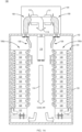
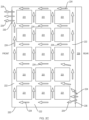
- FIG. 1A illustrates an example embodiment of a component cooling system 100 according to the invention.
- the component cooling system 100 comprises an enclosure 102, an air cooling system 104, and two equipment racks 106a, 106b.
- the air cooling system 104 may be mounted on the top of, and outside of, the enclosure 102.
- the air cooling system 104 may receive warm air 108 from the enclosure 102 through at least one warm air port 110 located at the top of the enclosure 102, and cool the received warm air 108 by passing the received warm air 108 through at least one air cooling unit 112.
- the cool air 114 produced by the air cooling unit 112 is channeled back into the enclosure 102 through at least one cool air port 116 located at the top of the enclosure 102.
- the flow of cool air 114 is shown with plain shaded arrows, while the flow of heated air 108 is shown with cross-hatched shaded arrows.
- a cool air duct 118 attached to the cool air port 116, extends at least part way down into the enclosure 102 toward the enclosure floor.
- the cool air duct 118 isolates the cooled air 114 from the warm air 108 in the upper portions of the enclosure 102 to prevent mixing of the warm air 108 and the cool air 114. This isolation of warm air from cool air may increase the overall thermal efficiency of the overall air component cooling system 100.
- the outlet of the cool air duct 118 may be disposed within a range of 40% to 60% of a floor-to-ceiling distance, although other embodiments may have the outlet of the cool air duct disposed in other floor-to-ceiling ranges.
- the cool air duct may be fabricated from a flexible material such as cloth or soft plastic. Such a flexible material may be advantageous for ensuring the safety of personnel working within the enclosure, in case the personnel inadvertently bumps into the cool air duct 118.
- Each equipment rack 106a, 106b includes two or more heat dissipating components 120 configured in a stacked arrangement.
- Each of the racks 106a, 106b includes a front opening and a rear opening. The front opening exposes the front portion of each heat dissipating component 120, and the rear opening exposes the rear portion of each heat dissipating component 120.
- the heat dissipating components 120 may comprise any device capable of dissipating heat energy.
- the heat dissipating components may include battery modules or other energy storage elements.
- Each equipment rack 106a, 106b may include three or more such battery modules.
- the heat dissipating component may comprise a battery management module for controlling, balancing and otherwise managing a set of battery modules.
- Each rack 106a, 106b further includes an air mover 122 disposed at the bottom of the rack.
- the air mover 122 may comprise a module with a footprint similar to that of a heat dissipating component, so that the air mover may be mounted to the rack with attachment hardware similar to that used to attach the heat dissipating components 120 to the equipment rack, although other form factors of the air mover 122 may alternatively be used.
- the air mover 122 may further comprise a fan having pitched blades attached to a rotatable axle as is known in the art.
- the fan may be a variable speed fan that changes a rate of air flow through the air mover 122, based upon a control input.
- the control input may respond to one or more temperature sensors within the enclosure 102 and/or the rack 106.
- the air mover 122 may alternatively comprise other mechanisms known in the art for causing air to flow across a pathway.
- the air mover 122 disposed at the bottom of each rack 106a, 106b is the only active component included in the rack to facilitate a flow of air through the heat dissipating components 120. In such embodiments, no other fans or air movers are required to be deployed within the individual heat dissipating components to facilitate or otherwise assist a flow of air through the components 120.
- the air mover 122 pulls air from the bottom portion of the enclosure (i.e., at the floor of the enclosure) and forces the air into an air plenum 124 mounted to the rear opening of the respective rack 106a, 106b.
- the air plenum 124 is a covering that creates an air channel 126 behind the stack of two or more heat dissipating components 120.
- the locations where the air plenum 124 contacts the rack 102 are configured to be air-tight or nearly air-tight, so that when the air mover 122 pressurizes the air plenum (by forcing air into the air channel 126), the only path for the pressurized air is through openings in the rear portions of the heat dissipating components 120 and through and/or around the heat dissipating components 120.
- FIGs. 1A and 1B show the racks 106a, 106b with a space between air mover 122 and the bottom of the enclosure 102, such that the air mover 122 draws air from directly underneath the rack 106a, 106b.
- the racks 106a, 106b may be situated directly on the enclosure floor, with no space beneath, so that the air mover 122 draws air from the front of the bottom of the rack rather than underneath the rack.
- FIG. 1D An example of such an alternative embodiment is shown in FIG. 1D .
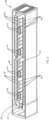
- FIG. 2A shows a perspective view of the equipment rack 106a, showing the air plenum 124 attached to the rear portion of the rack 106a.
- FIG. 2B illustrates a perspective view of the equipment rack 106a with the air plenum removed.
- the rear portion of each heat dissipating component 120 is exposed in the FIG. 2B view, with various connectors 202, control features 204 (e.g., switches, buttons) and air inlet ports 206 shown.
- control features 204 e.g., switches, buttons
- the air mover 122 may further comprise one or more air outlet ports 208, through which the air mover 122 drives cool air into the air channel 126 formed when the plenum is attached to the rack 106a.
- the air plenum 124 in the example embodiments are shown as a rectangular, box-shaped item, it should be understood that the air plenum 124 may be formed in alternative shapes, provided that the plenum creates the sealed, airtight (or nearly so) air channel 126 behind the heat dissipating components 120 as described herein. Further, it should be understood that the air plenum edge 210 (which contacts the rack 106a when the air plenum 124 is attached to the rack 106a) may include a gasket, or other sealing agent, attached thereto, to reinforce the seal between the air plenum 124 and the rack 106a.
- the air mover 122 pulls cool air, which is at enclosure-ambient pressure, from the bottom of the enclosure 102, and forces the cool air into the air channel 126 formed by the air plenum 124, thereby pressurizing the air plenum 124 to a pressure above enclosure-ambient pressure.
- the pressurized air plenum causes a flow of air through or around each heat dissipating component 120to the lower pressure region at the front portion of the heat dissipating component 120 which is in the region between the equipment racks 106a, 106b.
- the heat dissipating components 120 may be configured to include intake ports, exit ports, air channels, pathways, baffles, and other features to cause air to pass through or around the heat dissipating component 120 efficiently.
- the rear portion of the heat dissipating component may include one or more intake ports distributed across the rear face of the heat dissipating component 120.
- one or more intake ports may be disposed on one side of the rear face of the heat dissipating component, with an exit port disposed on the opposite side at the front face of the heat dissipating component 120.
- FIG. 2C illustrates a top cross-sectional view of an example embodiment of an heat dissipating component 220 containing sub-components 221.
- the view in FIG. 2C shows air channels 222 through the component 220, allowing a flow 224 of air to pass from the air plenum 226, through a rear intake port 228, through the channels 222, and to an exit port 230 to exit at the front of the heat dissipating component 220.
- air flow 224 indicators shaded arrows
- FIG. 2D illustrates a side sectional view of an example embodiment of three stacked heat dissipating components 230 in a rack, configured so that air passes between the devices from the rear of the component 230 to the front of the component.
- the view in FIG. 2D shows a flow 232 of air passing from the air plenum 234 through the channels 236 formed by a top 238 and a bottom 240 of adjacent components 230, and the rack sides (not shown) to which the components 230 are attached.
- FIGs. 2C and 2D are presented to demonstrate ways that a flow of air may be employed to cool components, and are not meant to be limiting. Other configurations of air channels and pathways associated with the components to be cooled may be used instead of or in addition to the configurations described above. Further, a configuration that passes air through the component, as in FIG. 2C , may be used in combination with a configuration that passes air along the exterior surfaces of the component, as in FIG. 2D .
- the cool air that originates from the air channel 126 may absorb heat energy dissipated from the heat dissipating component 120 (and/or sub-components within the heat dissipating component 120), as the cool air passes through the component 120, thereby raising the temperature of the air passing through the heat dissipating component 120.
- the temperature of the air exiting the heat dissipating component 120 is therefore higher than the air entering the component 120 from the air plenum.
- the air channels, pathways, baffles, and other features for conveying air through the heat dissipating component 120 may further be designed to cause heat energy to be efficiently transferred from the heat dissipating component 120 and sub-components to the air passing through the component 120.
- the warm air exiting the heat dissipating component 120 tends to rise to the top of the enclosure 102 due to thermal convection.
- the air cooling system 104 withdraws the warm air 108 at the top of the enclosure 102, through one or more warm air ports 110, and cools the warm air 108 through one or more cooling units 112 known in the art.
- each of the cooling units may be a compression/expansion refrigeration cycle system, although other cooling systems known in the art may be used instead of or in addition to a compression/expansion refrigeration cycle system.
- the cool air may flow between adjacent pairs of heat dissipating components 122, instead of (or in addition to) flowing through the heat dissipating components 122.
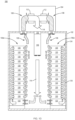
- FIG. 1A illustrates two equipment racks 106a and 106b, although it should be understood that the concepts described herein are applicable with one equipment rack, as shown in the example embodiment of FIG. 1B , or with more than two equipment racks 106a through 106f, as shown in the example embodiment of FIG. 1C .
- the embodiment of FIG. 1C includes certain pairs of racks configured back-to-back, such that the plenum of one back-to-back rack is adjacent to the plenum of the other back-to-back rack.
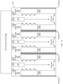
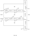
- FIG. 3 illustrates a perspective view of an embodiment consistent with the embodiment of FIG. 1A , having two parallel rows of equipment racks within an enclosure.
- a first row 302 of racks 304 is situated against one long side wall 306 of the enclosure 308, and a second row 310 of racks 304 is situated against another long side wall 312 of the enclosure 308.
- the view shown in FIG. 3 has the ceiling of the enclosure 308 and the cooling system removed, to allow the rows of racks to be seen.
- only some of the racks 304 are labeled with reference numbers. In the embodiment of FIG.
- the racks 304 within each row 302, 310 are arranged side by side with the rear portion of each rack (i.e., the plenum) adjacent to the enclosure side wall 306, 312. Pairs of cool air ducts 318, disconnected from the associated cool air ports in the enclosure ceiling, are shown extending down into the enclosure between the rows 302, 310 of racks 304.
- the concept of rows of racks within an enclosure, demonstrated in FIG. 3 can be extended to embodiments of more than two rows as depicted for example in FIG. 1C .
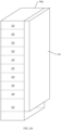
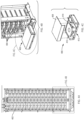
- FIG. 4A shows a front view of a single example equipment rack 402 constructed according to the invention.
- This example embodiment has 16 battery modules 404, and one battery management module 405, arranged in a stacked configuration, with a single air mover module 406 disposed at the bottom of the rack 402.
- FIG. 4B is a more detailed view of the bottom of the rack 402 shown in FIG. 4A .
- the view of FIG. 4b shows four of the battery modules 404, and the air mover module 406 is shown partially extracted from the rack 402.
- Each module 404, 406 may be individually extracted for replacement, repair or other maintenance as required.
- FIG. 4C shows the air mover module 406 partially disassembled, with the cover 408 removed, exposing the electric rotary 2fan assembly 410.
- the fan assembly 410 pulls air through a first aperture 412 in the bottom of the air mover module 406, and forces the air through a second aperture 414 and into the air plenum (not shown).
- the use of a single air mover for each rack, rather than one for each component or module, allows for a less expensive system while using a relatively high quality air mover for greater efficiency, reliability and longer life.
- the air plenum is dimensioned such that the pressure drop through the height of the air plenum is low relative to the pressure drop across each component or module.
- the resistance to air flow through the components or modules is generally the same but may be varied to control relative flow through the components or modules.
Landscapes
- Engineering & Computer Science (AREA)
- Chemical & Material Sciences (AREA)
- Chemical Kinetics & Catalysis (AREA)
- Electrochemistry (AREA)
- General Chemical & Material Sciences (AREA)
- Manufacturing & Machinery (AREA)
- Computer Hardware Design (AREA)
- General Engineering & Computer Science (AREA)
- Physics & Mathematics (AREA)
- Thermal Sciences (AREA)
- Microelectronics & Electronic Packaging (AREA)
- Cooling Or The Like Of Electrical Apparatus (AREA)
- Secondary Cells (AREA)
- Cold Air Circulating Systems And Constructional Details In Refrigerators (AREA)
Priority Applications (2)
| Application Number | Priority Date | Filing Date | Title |
|---|---|---|---|
| HRP20250854TT HRP20250854T1 (hr) | 2017-01-03 | 2017-12-18 | Sustav za hlađenje komponenata koje se nalaze u kućištu |
| RS20250702A RS67010B1 (sr) | 2017-01-03 | 2017-12-18 | Sistem za hlađenje komponenti koje su ugrađene u kućište |
Applications Claiming Priority (2)
| Application Number | Priority Date | Filing Date | Title |
|---|---|---|---|
| US15/397,256 US11978875B2 (en) | 2017-01-03 | 2017-01-03 | System for cooling components arranged within an enclosure |
| PCT/US2017/066952 WO2018128783A1 (en) | 2017-01-03 | 2017-12-18 | A system for cooling components arranged within an enclosure |
Publications (3)
| Publication Number | Publication Date |
|---|---|
| EP3545733A1 EP3545733A1 (en) | 2019-10-02 |
| EP3545733B1 true EP3545733B1 (en) | 2025-05-14 |
| EP3545733C0 EP3545733C0 (en) | 2025-05-14 |
Family
ID=61007793
Family Applications (1)
| Application Number | Title | Priority Date | Filing Date |
|---|---|---|---|
| EP17832637.7A Active EP3545733B1 (en) | 2017-01-03 | 2017-12-18 | A system for cooling components arranged within an enclosure |
Country Status (11)
| Country | Link |
|---|---|
| US (2) | US11978875B2 (enExample) |
| EP (1) | EP3545733B1 (enExample) |
| JP (2) | JP7261161B2 (enExample) |
| KR (1) | KR102579774B1 (enExample) |
| CN (1) | CN110235535A (enExample) |
| ES (1) | ES3032617T3 (enExample) |
| HR (1) | HRP20250854T1 (enExample) |
| HU (1) | HUE072295T2 (enExample) |
| PL (1) | PL3545733T3 (enExample) |
| RS (1) | RS67010B1 (enExample) |
| WO (1) | WO2018128783A1 (enExample) |
Families Citing this family (13)
| Publication number | Priority date | Publication date | Assignee | Title |
|---|---|---|---|---|
| US10993353B2 (en) * | 2014-09-29 | 2021-04-27 | Hewlett Packard Enterprise Development Lp | Fan controlled ambient air cooling of equipment in a controlled airflow environment |
| CN107710495B (zh) * | 2015-07-24 | 2020-12-01 | 松下知识产权经营株式会社 | 温度调节单元、温度调节系统、车辆 |
| US10736231B2 (en) * | 2016-06-14 | 2020-08-04 | Dell Products L.P. | Modular data center with passively-cooled utility module |
| FR3055983A1 (fr) * | 2016-09-14 | 2018-03-16 | Vernet | Dispositif de regulation thermostatique d'un fluide |
| KR102212034B1 (ko) * | 2018-12-13 | 2021-02-04 | 보성파워텍 주식회사 | 에너지 저장 시스템이 적용된 컨테이너 |
| US12100823B2 (en) * | 2019-08-09 | 2024-09-24 | Kabushiki Kaisha Toshiba | Cooling system |
| EP4147297A4 (en) * | 2020-05-04 | 2024-08-07 | Fluence Energy, LLC | ENERGY STORAGE SYSTEM WITH REMOVABLE, ADJUSTABLE AND LIGHTWEIGHT PLENUMS |
| KR102861151B1 (ko) * | 2020-10-27 | 2025-09-16 | 주식회사 엘지에너지솔루션 | 배터리 랙 및 이러한 배터리 랙을 포함하는 전력 저장 장치 |
| CN112670617A (zh) * | 2020-12-23 | 2021-04-16 | 林玉珍 | 一种新能源电池管理用散热机构 |
| EP4117406A4 (en) * | 2021-04-13 | 2023-06-21 | Contemporary Amperex Technology Co., Limited | FAN ASSEMBLY, POWER SUPPLY DEVICE AND METHOD OF MANUFACTURING FOR POWER SUPPLY DEVICE |
| CN113471574B (zh) * | 2021-09-02 | 2022-01-04 | 深圳联钜自控科技有限公司 | 一种温度控制装置及方法 |
| CN216698514U (zh) * | 2021-09-26 | 2022-06-07 | 华为数字能源技术有限公司 | 储能系统 |
| TWI805035B (zh) * | 2021-10-20 | 2023-06-11 | 利佳興業股份有限公司 | 具有散熱均溫系統的儲能櫃 |
Citations (2)
| Publication number | Priority date | Publication date | Assignee | Title |
|---|---|---|---|---|
| US20020100579A1 (en) * | 2001-01-31 | 2002-08-01 | Timo Heikkila | Cooling an apparatus cabinet |
| JP2003166729A (ja) * | 2001-11-30 | 2003-06-13 | Takasago Thermal Eng Co Ltd | 通信・情報処理機器室等の空調システム |
Family Cites Families (35)
| Publication number | Priority date | Publication date | Assignee | Title |
|---|---|---|---|---|
| JP2623742B2 (ja) | 1988-08-16 | 1997-06-25 | 日本電気株式会社 | 異常共振防止プリント基板 |
| JPH0252493U (enExample) * | 1988-10-07 | 1990-04-16 | ||
| US6330925B1 (en) * | 1997-01-31 | 2001-12-18 | Ovonic Battery Company, Inc. | Hybrid electric vehicle incorporating an integrated propulsion system |
| JP3844839B2 (ja) | 1997-03-07 | 2006-11-15 | ヤンマー株式会社 | V型ディーゼルエンジン |
| US6034873A (en) | 1998-06-02 | 2000-03-07 | Ericsson Inc | System and method for separating air flows in a cooling system |
| FR2831019B1 (fr) | 2001-10-12 | 2004-07-09 | Legrand Sa | Armoire refrigeree pour appareillage electrique ou electronique, comportant un circuit de ventilation perfectionne |
| JP4422935B2 (ja) | 2001-11-06 | 2010-03-03 | 三菱電機株式会社 | 空調システム |
| US6628520B2 (en) | 2002-02-06 | 2003-09-30 | Hewlett-Packard Development Company, L.P. | Method, apparatus, and system for cooling electronic components |
| JP4314044B2 (ja) * | 2003-03-18 | 2009-08-12 | パナソニックEvエナジー株式会社 | 電池パック |
| US7508663B2 (en) | 2003-12-29 | 2009-03-24 | Rackable Systems, Inc. | Computer rack cooling system with variable airflow impedance |
| WO2006055387A1 (en) | 2004-11-14 | 2006-05-26 | Liebert Corporation | Integrated heat exchanger(s) in a rack for vertical board style computer systems |
| ITPD20040303A1 (it) | 2004-11-30 | 2005-02-28 | Liebert Hiross Spa | Apparecchiatura di condizionamento particolarmente per racks per strumenti elettrici, elettronici, di telecomunicazioni o simili |
| US7438124B2 (en) | 2005-10-04 | 2008-10-21 | Delphi Technologies, Inc. | Evaporative cooling system for a data-communications cabinet |
| WO2007139560A1 (en) | 2006-06-01 | 2007-12-06 | Google, Inc. | Modular computing environments |
| US20070283710A1 (en) | 2006-06-12 | 2007-12-13 | Sun Microsystems, Inc. | Method and system for cooling electronic equipment |
| US7857688B1 (en) | 2006-12-11 | 2010-12-28 | Emc Corporation | Electrical cabinet having multi-channel exhaust with bleeding vents to alleviate back-pressure |
| US7430118B1 (en) * | 2007-06-04 | 2008-09-30 | Yahoo! Inc. | Cold row encapsulation for server farm cooling system |
| US8763414B2 (en) | 2008-03-31 | 2014-07-01 | Google Inc. | Warm floor data center |
| JP4951596B2 (ja) | 2008-07-31 | 2012-06-13 | 株式会社日立製作所 | 冷却システム及び電子装置 |
| JP2010061446A (ja) | 2008-09-04 | 2010-03-18 | Gac Corp | サーバークーラーシステム |
| JP2009133617A (ja) | 2009-03-11 | 2009-06-18 | Takasago Thermal Eng Co Ltd | 空調システム |
| TW201115082A (en) | 2009-10-16 | 2011-05-01 | Law Chain Comp Technology Co Ltd | Method for improving energy saving of air condition of equipment room |
| JP5496604B2 (ja) * | 2009-10-30 | 2014-05-21 | 三洋電機株式会社 | 電源装置及びこれを備える車両 |
| CN102131369B (zh) | 2010-01-20 | 2014-09-17 | 华为技术有限公司 | 一种集装箱式数据中心 |
| TW201210433A (en) | 2010-08-18 | 2012-03-01 | Hon Hai Prec Ind Co Ltd | Computer server cabinet |
| TW201214096A (en) | 2010-09-28 | 2012-04-01 | Hon Hai Prec Ind Co Ltd | Container data center and power generation system thereof |
| TW201222219A (en) | 2010-11-25 | 2012-06-01 | Hon Hai Prec Ind Co Ltd | Data center |
| CN102742375B (zh) | 2010-12-07 | 2015-06-10 | 北京纳源丰科技发展有限公司 | 一种制冷一体化机柜 |
| US20140011059A1 (en) * | 2011-03-31 | 2014-01-09 | Hiroyuki Hashimoto | Power supply device and vehicle equipped therewith |
| KR102028919B1 (ko) * | 2012-06-08 | 2019-10-07 | 에스케이이노베이션 주식회사 | 배터리 팩 |
| EP2973841B1 (en) * | 2013-03-14 | 2018-11-14 | Allison Transmission, Inc. | Fluid bath cooled energy storage system |
| JP2015125577A (ja) | 2013-12-26 | 2015-07-06 | 株式会社日立システムズ | サーバ冷却設備 |
| JP6382067B2 (ja) * | 2014-10-27 | 2018-08-29 | 株式会社協豊製作所 | 電池パック |
| WO2016196968A1 (en) | 2015-06-04 | 2016-12-08 | Nec Energy Solutions, Inc. | Utilizing a load for optimizing energy storage size and operation in power systems regulation applications |
| CN205029550U (zh) * | 2015-10-23 | 2016-02-10 | 北京天诚同创电气有限公司 | 变流器及风力发电机组 |
-
2017
- 2017-01-03 US US15/397,256 patent/US11978875B2/en active Active
- 2017-12-18 RS RS20250702A patent/RS67010B1/sr unknown
- 2017-12-18 CN CN201780082110.9A patent/CN110235535A/zh active Pending
- 2017-12-18 HU HUE17832637A patent/HUE072295T2/hu unknown
- 2017-12-18 WO PCT/US2017/066952 patent/WO2018128783A1/en not_active Ceased
- 2017-12-18 JP JP2019536221A patent/JP7261161B2/ja active Active
- 2017-12-18 HR HRP20250854TT patent/HRP20250854T1/hr unknown
- 2017-12-18 ES ES17832637T patent/ES3032617T3/es active Active
- 2017-12-18 PL PL17832637.7T patent/PL3545733T3/pl unknown
- 2017-12-18 KR KR1020197021038A patent/KR102579774B1/ko active Active
- 2017-12-18 EP EP17832637.7A patent/EP3545733B1/en active Active
-
2023
- 2023-04-07 JP JP2023062947A patent/JP7585380B2/ja active Active
-
2024
- 2024-05-06 US US18/656,096 patent/US12444786B2/en active Active
Patent Citations (2)
| Publication number | Priority date | Publication date | Assignee | Title |
|---|---|---|---|---|
| US20020100579A1 (en) * | 2001-01-31 | 2002-08-01 | Timo Heikkila | Cooling an apparatus cabinet |
| JP2003166729A (ja) * | 2001-11-30 | 2003-06-13 | Takasago Thermal Eng Co Ltd | 通信・情報処理機器室等の空調システム |
Also Published As
| Publication number | Publication date |
|---|---|
| HRP20250854T1 (hr) | 2025-09-26 |
| JP2023090735A (ja) | 2023-06-29 |
| JP7585380B2 (ja) | 2024-11-18 |
| EP3545733A1 (en) | 2019-10-02 |
| PL3545733T3 (pl) | 2025-10-06 |
| KR102579774B1 (ko) | 2023-09-19 |
| US12444786B2 (en) | 2025-10-14 |
| JP7261161B2 (ja) | 2023-04-19 |
| ES3032617T3 (en) | 2025-07-22 |
| KR20190102217A (ko) | 2019-09-03 |
| US20240291068A1 (en) | 2024-08-29 |
| HUE072295T2 (hu) | 2025-11-28 |
| US11978875B2 (en) | 2024-05-07 |
| RS67010B1 (sr) | 2025-08-29 |
| JP2020504885A (ja) | 2020-02-13 |
| WO2018128783A1 (en) | 2018-07-12 |
| US20180191043A1 (en) | 2018-07-05 |
| CN110235535A (zh) | 2019-09-13 |
| EP3545733C0 (en) | 2025-05-14 |
Similar Documents
| Publication | Publication Date | Title |
|---|---|---|
| US12444786B2 (en) | System for cooling components arranged within an enclosure | |
| US11927363B2 (en) | Air curtain containment system and assembly for data centers | |
| US7254022B2 (en) | Cooling system for equipment and network cabinets and method for cooling equipment and network cabinets | |
| US6506111B2 (en) | Cooling airflow distribution device | |
| EP1774842B2 (en) | Data center cooling | |
| US8141621B2 (en) | Apparatus and method for providing in situ cooling of computer data centers during service calls | |
| US20090061755A1 (en) | Intake Duct | |
| WO2006071987A2 (en) | Rack height cooling | |
| US10701830B1 (en) | Data center cooling device | |
| US20120100795A1 (en) | Air-conditioning system | |
| EP2362721A1 (en) | Method and system for cooling apparatus racks | |
| US20190357390A1 (en) | Fan apparatuses for chassis airflow | |
| US20190357380A1 (en) | Apparatuses to vent air therethrough | |
| GB2387716A (en) | Cooling electrical circuitry | |
| US11134588B2 (en) | Crossflow air cooling module for electronic equipment | |
| EP3046108B1 (en) | Modular ducting solution |
Legal Events
| Date | Code | Title | Description |
|---|---|---|---|
| REG | Reference to a national code |
Ref country code: HR Ref legal event code: TUEP Ref document number: P20250854T Country of ref document: HR |
|
| STAA | Information on the status of an ep patent application or granted ep patent |
Free format text: STATUS: UNKNOWN |
|
| STAA | Information on the status of an ep patent application or granted ep patent |
Free format text: STATUS: THE INTERNATIONAL PUBLICATION HAS BEEN MADE |
|
| PUAI | Public reference made under article 153(3) epc to a published international application that has entered the european phase |
Free format text: ORIGINAL CODE: 0009012 |
|
| STAA | Information on the status of an ep patent application or granted ep patent |
Free format text: STATUS: REQUEST FOR EXAMINATION WAS MADE |
|
| 17P | Request for examination filed |
Effective date: 20190628 |
|
| AK | Designated contracting states |
Kind code of ref document: A1 Designated state(s): AL AT BE BG CH CY CZ DE DK EE ES FI FR GB GR HR HU IE IS IT LI LT LU LV MC MK MT NL NO PL PT RO RS SE SI SK SM TR |
|
| AX | Request for extension of the european patent |
Extension state: BA ME |
|
| RIN1 | Information on inventor provided before grant (corrected) |
Inventor name: REITSMA, SCOTT Inventor name: TELA, JAMES S. Inventor name: NELSON, ERIK C. Inventor name: NELSON, BRYAN |
|
| DAV | Request for validation of the european patent (deleted) | ||
| DAX | Request for extension of the european patent (deleted) | ||
| STAA | Information on the status of an ep patent application or granted ep patent |
Free format text: STATUS: EXAMINATION IS IN PROGRESS |
|
| 17Q | First examination report despatched |
Effective date: 20211202 |
|
| RAP3 | Party data changed (applicant data changed or rights of an application transferred) |
Owner name: LG ENERGY SOLUTION VERTECH, INC. |
|
| GRAP | Despatch of communication of intention to grant a patent |
Free format text: ORIGINAL CODE: EPIDOSNIGR1 |
|
| STAA | Information on the status of an ep patent application or granted ep patent |
Free format text: STATUS: GRANT OF PATENT IS INTENDED |
|
| INTG | Intention to grant announced |
Effective date: 20240426 |
|
| GRAJ | Information related to disapproval of communication of intention to grant by the applicant or resumption of examination proceedings by the epo deleted |
Free format text: ORIGINAL CODE: EPIDOSDIGR1 |
|
| STAA | Information on the status of an ep patent application or granted ep patent |
Free format text: STATUS: EXAMINATION IS IN PROGRESS |
|
| GRAP | Despatch of communication of intention to grant a patent |
Free format text: ORIGINAL CODE: EPIDOSNIGR1 |
|
| STAA | Information on the status of an ep patent application or granted ep patent |
Free format text: STATUS: GRANT OF PATENT IS INTENDED |
|
| INTC | Intention to grant announced (deleted) | ||
| INTG | Intention to grant announced |
Effective date: 20240918 |
|
| GRAS | Grant fee paid |
Free format text: ORIGINAL CODE: EPIDOSNIGR3 |
|
| P01 | Opt-out of the competence of the unified patent court (upc) registered |
Free format text: CASE NUMBER: APP_65216/2024 Effective date: 20241210 |
|
| GRAA | (expected) grant |
Free format text: ORIGINAL CODE: 0009210 |
|
| STAA | Information on the status of an ep patent application or granted ep patent |
Free format text: STATUS: THE PATENT HAS BEEN GRANTED |
|
| AK | Designated contracting states |
Kind code of ref document: B1 Designated state(s): AL AT BE BG CH CY CZ DE DK EE ES FI FR GB GR HR HU IE IS IT LI LT LU LV MC MK MT NL NO PL PT RO RS SE SI SK SM TR |
|
| REG | Reference to a national code |
Ref country code: GB Ref legal event code: FG4D |
|
| REG | Reference to a national code |
Ref country code: CH Ref legal event code: EP |
|
| REG | Reference to a national code |
Ref country code: IE Ref legal event code: FG4D |
|
| REG | Reference to a national code |
Ref country code: DE Ref legal event code: R096 Ref document number: 602017089479 Country of ref document: DE |
|
| U01 | Request for unitary effect filed |
Effective date: 20250604 |
|
| P04 | Withdrawal of opt-out of the competence of the unified patent court (upc) registered |
Free format text: CASE NUMBER: APP_27227/2025 Effective date: 20250607 |
|
| U07 | Unitary effect registered |
Designated state(s): AT BE BG DE DK EE FI FR IT LT LU LV MT NL PT RO SE SI Effective date: 20250612 |
|
| REG | Reference to a national code |
Ref country code: ES Ref legal event code: FG2A Ref document number: 3032617 Country of ref document: ES Kind code of ref document: T3 Effective date: 20250722 |
|
| REG | Reference to a national code |
Ref country code: GR Ref legal event code: EP Ref document number: 20250401470 Country of ref document: GR Effective date: 20250808 |
|
| REG | Reference to a national code |
Ref country code: HR Ref legal event code: T1PR Ref document number: P20250854 Country of ref document: HR |
|
| PG25 | Lapsed in a contracting state [announced via postgrant information from national office to epo] |
Ref country code: IS Free format text: LAPSE BECAUSE OF FAILURE TO SUBMIT A TRANSLATION OF THE DESCRIPTION OR TO PAY THE FEE WITHIN THE PRESCRIBED TIME-LIMIT Effective date: 20250914 |
|
| REG | Reference to a national code |
Ref country code: HU Ref legal event code: AG4A Ref document number: E072295 Country of ref document: HU |
|
| REG | Reference to a national code |
Ref country code: SK Ref legal event code: T3 Ref document number: E 47372 Country of ref document: SK |