EP3545512B1 - Anzeigeschild - Google Patents
Anzeigeschild Download PDFInfo
- Publication number
- EP3545512B1 EP3545512B1 EP17801048.4A EP17801048A EP3545512B1 EP 3545512 B1 EP3545512 B1 EP 3545512B1 EP 17801048 A EP17801048 A EP 17801048A EP 3545512 B1 EP3545512 B1 EP 3545512B1
- Authority
- EP
- European Patent Office
- Prior art keywords
- slider
- movable body
- main body
- sign
- display
- Prior art date
- Legal status (The legal status is an assumption and is not a legal conclusion. Google has not performed a legal analysis and makes no representation as to the accuracy of the status listed.)
- Active
Links
Images


Classifications
-
- G—PHYSICS
- G09—EDUCATION; CRYPTOGRAPHY; DISPLAY; ADVERTISING; SEALS
- G09F—DISPLAYING; ADVERTISING; SIGNS; LABELS OR NAME-PLATES; SEALS
- G09F7/00—Signs, name or number plates, letters, numerals, or symbols; Panels or boards
- G09F7/02—Signs, plates, panels or boards using readily-detachable elements bearing or forming symbols
- G09F7/08—Signs, plates, panels or boards using readily-detachable elements bearing or forming symbols the elements being secured or adapted to be secured by means of grooves, rails, or slits
- G09F7/10—Signs, plates, panels or boards using readily-detachable elements bearing or forming symbols the elements being secured or adapted to be secured by means of grooves, rails, or slits and slideably mounted
-
- G—PHYSICS
- G09—EDUCATION; CRYPTOGRAPHY; DISPLAY; ADVERTISING; SEALS
- G09F—DISPLAYING; ADVERTISING; SIGNS; LABELS OR NAME-PLATES; SEALS
- G09F23/00—Advertising on or in specific articles, e.g. ashtrays, letter-boxes
- G09F23/06—Advertising on or in specific articles, e.g. ashtrays, letter-boxes the advertising matter being combined with articles for restaurants, shops or offices
-
- G—PHYSICS
- G09—EDUCATION; CRYPTOGRAPHY; DISPLAY; ADVERTISING; SEALS
- G09F—DISPLAYING; ADVERTISING; SIGNS; LABELS OR NAME-PLATES; SEALS
- G09F7/00—Signs, name or number plates, letters, numerals, or symbols; Panels or boards
- G09F7/02—Signs, plates, panels or boards using readily-detachable elements bearing or forming symbols
- G09F7/08—Signs, plates, panels or boards using readily-detachable elements bearing or forming symbols the elements being secured or adapted to be secured by means of grooves, rails, or slits
-
- G—PHYSICS
- G09—EDUCATION; CRYPTOGRAPHY; DISPLAY; ADVERTISING; SEALS
- G09F—DISPLAYING; ADVERTISING; SIGNS; LABELS OR NAME-PLATES; SEALS
- G09F7/00—Signs, name or number plates, letters, numerals, or symbols; Panels or boards
- G09F7/18—Means for attaching signs, plates, panels, or boards to a supporting structure
- G09F7/20—Means for attaching signs, plates, panels, or boards to a supporting structure for adjustably mounting
-
- G—PHYSICS
- G09—EDUCATION; CRYPTOGRAPHY; DISPLAY; ADVERTISING; SEALS
- G09F—DISPLAYING; ADVERTISING; SIGNS; LABELS OR NAME-PLATES; SEALS
- G09F7/00—Signs, name or number plates, letters, numerals, or symbols; Panels or boards
- G09F2007/007—Signs without covering windows
Definitions
- the present invention relates to a display sign, such as for an office or built environment, and especially in identifying rooms within buildings.
- US8733000 relates to an advertisement display and method of use.
- the document discloses a display having two side columns and at least one advertisement module provided therebetween.
- the module consists of a top unit and a pivoting lower unit.
- the top unit is slidable within the side columns.
- a longitudinal wall is spaced from a bottom wall of the top unit defining a utility space therebetween.
- the lower unit is locked and prevented from pivoting when the top unit with the longitudinal wall is slid into a downward position, and is allowed to pivot when the top unit with the longitudinal wall is slid upwardly unlocking the bottom unit.
- US8808006 relates to a multiplanar display system.
- the document discloses a display system that combines a dry-erase surface with an interchangeable background made to specific individual requirements so that information and/ or fields over which dry-erase markings are made become integrated with the background.
- a picture frame referred to as a snap frame, having spring-loaded movable clamps hinged to fixed frame members, which are further attached to a rigid backer board to form a composite four sided rigid member.
- the document further illustrates a snap frame where movable members are rotated outwardly to facilitate removal of a transparent cover member, from the front, in order to access a background.
- a replacement background may be positioned within the fixed frame, interposed between the backer board, and the clear cover, which protects the background once it is secured in place by snapping movable members to a closed position.
- US5657566 relates to rapid mount advertising panels.
- the document discloses advertising panels for motor vehicles, such as lorries, wherein a plurality of panels are removably attached in such a manner, that as a group they form a large bill board surface.
- the display panels are constructed and designed to resist sagging and distortion due to the effect of heat, wind, etc. when the truck is moving.
- the present invention provides a display sign according to claim 1, comprising: a main body; a display section; and a movable body, which is movable in relation to the main body and configured to provide for locking and release of the display section so as to allow for removal and/or replacement of at least part of the display section
- the main body includes a cavity and the movable body comprises a slider which is slideably disposed in the cavity of the main body characterised in that the slider includes at least one recess which is disposed adjacent at least one first engagement element of the slider, the recesses each having a width which is greater than the width of first engagement elements of the main body, such that, when the slider is moved in a first direction, the recesses in the slider can be aligned with the first engagement elements of the main body, which allows the movable body to be moved in a second direction, orthogonal to the first direction, with the first engagement elements of the main body being received in the recesses in the slider.
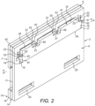
- the display sign comprises a main body 3, a display section 5 and a movable body 7, which is movable in relation to the main body 3 and configured to provide for locking and release of the display section 5 so as to allow for removal and/or replacement of at least part of the display section 5; wherein the main body 3 includes a cavity 17 and the movable body 7 comprises a slider 41 which is slideably disposed in the cavity 17 of the main body 3 characterised in that the slider 41 includes at least one recess 65 which is disposed adjacent at least one first engagement element 51 of the slider 41, the recesses 65 each having a width which is greater than the width of first engagement elements 20 of the main body 3, such that, when the slider 41 is moved in a first direction, the recesses 65 in the slider 41 can be aligned with the first engagement elements 20 of the main body 3, which allows the movable body 7 to be moved in a second direction, orthogonal to the first direction, with the first engagement elements 20 of the main body 3 being received in the recesses 65 in the slider 4.
- the main body 3 is formed of sheets or panels, here of plastics material, which are bonded, such as by adhesive.
- the main body 3 comprises a rear section 8, which is mounted to a wall or other building structure, a spacer 9 which is disposed to one, front face of the rear section 8 and spaces a face panel 43 of the movable body 7 from the rear section 8, and an engagement section 10 to which the display section 5 is engaged.
- the spacer 9 and the engagement section 10 define a recess 11 therebetween, in which the display section 5 is disposed.
- the spacer 9, as particularly illustrated in Figure 6 includes an aperture 12 which is shaped captively to retain a slider 41 of the movable body 7, but allow movement of the movable body 7 in first and second orthogonal directions X, Y.
- the engagement section 10 comprises an engagement element 14, which is attached to the front face of the rear section 8 and includes at least one recess, here a plurality of recesses 15, for receiving the display section 5, and a face panel 16, which is attached to the engagement element 14.
- the engagement section 10 provides a lower, footer to the display sign.
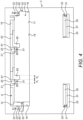
- the main body 3 includes a cavity 17, in which the slider 41 of the movable body 7 is slideable.
- the cavity 17 is substantially rectangular in profile and has opposed longitudinal sides 18 and opposed ends 19.
- the main body 3 includes at least one, here a plurality of first engagement elements 20, which are arranged in spaced relation.
- first engagement elements 20 are disposed to one, here the upper, of the longitudinal sides 18 of the cavity 17 and the other, here the lower, of the longitudinal sides 18 of the cavity 17 defines a sliding surface on which the slider 41 of the movable body 7 is slideable in the first direction X.
- first engagement elements 20 each include a detent 21, here at the distal end thereof.
- the first engagement elements 20 comprise projections which have a width d 1 and extend in the second direction Y.
- the main body 3 includes at least one, here a plurality of second engagement elements 22, which act to hold the slider 41 of the movable body 7 in a latched, open position, as will be described in more detail hereinbelow.
- the second engagement elements 22 are disposed to respective ends 19 of the cavity 17.
- the second engagement elements 22 are resilient elements, which engage corresponding engagement elements 52 on the slider 41 of the movable body 7.
- the second engagement elements 22 each include a detent 23, here in the form of a recess.
- the main body 3 includes at least one, here a plurality of openings 25, which receive hinge elements 35, 37 of the display section 5, as will be described in more detail hereinbelow.
- the display section 5 comprises a display insert 31 which bears information, and a display panel 33 which covers the display insert 31 to enclose the same.
- the display insert 31 includes at least one, here a plurality of tab elements 35, here at a lower edge thereof, which locate in the recesses 15 in the engagement section 10, and, with the movable body 7 in the unlocked position, the display section 5 allows for hinging of the display panel 33 and removal and/or replacement of the display insert 31.
- the display insert 31 is formed of paper, but could be formed of other materials, such as card or plastics sheet.
- the display panel 33 is at least partially transparent so as to allow information on the display insert 31 to be viewed.
- the display panel 33 includes at least one, here a plurality of tab elements 37, here at a lower edge thereof, which locate in the recesses 15 in the engagement section 10.
- the display section 5 could comprise only the display panel 33 which bears information.
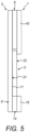
- the movable body 7 comprises a slider 41 which is captively disposed within the cavity 17 in the main body 3 and a face panel 43 which is attached to slider 41, such that the slider 41 is moved by movement of the face panel 43.
- the slider 41 is substantially rectangular in profile and has longitudinal sides 45 and ends 47.
- the slider 41 includes at least one, here a plurality of first engagement elements 51, which are arranged in spaced and counterpart relation to the first engagement elements 20 of the main body 3, and at least one, here a plurality of second engagement elements 52, which are arranged in spaced and counterpart relation to the second engagement elements 22 of the main body 3.
- first engagement elements 51 of the slider 41 are disposed to one of the longitudinal sides 45 of the slider 41 and the other of the longitudinal sides 47 of the slider 41 defines a sliding surface which engages the sliding surface of the other, lower longitudinal side 18 of the cavity 17 in the main body 3.
- first engagement elements 51 of the slider 41 each include a detent 61, here in the form of a recess, which engages the respective detent 21 on the counterpart first engagement element 20 of the main body 3.
- the first engagement elements 51 of the slider 41 are resilient elements, which allow the detents 21, 61 to be engaged and disengaged with movement of the movable body 7 in the first direction X.
- the second engagement elements 52 of the slider 41 each include a detent 62.
- the slider 41 includes at least one, here a plurality of recesses 65, which are disposed adjacent the at least one, here plurality of first engagement elements 51 of the slider 41.
- the recesses 65 each have a width d 2 which is greater than the width d 1 of the first engagement elements 20 of the main body 3, such that, when the slider 41 is moved in the first direction X, the recesses 65 in the slider 41 can be aligned with the first engagement elements 20 of the main body 3, which allows the movable body 7 to be moved in a second direction Y, orthogonal to the first direction X, with the first engagement elements 20 of the main body 3 being received in the recesses 65 in the slider 41, as will be described in more detail hereinbelow.
- the face panel 43 of the movable body 7 provides an upper, header of the display sign.
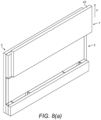
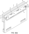
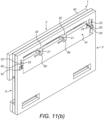
- the face panel 43 of the movable body 7 is slid in the first direction X, here laterally to the right, which causes the slider 41 to be moved in the first direction X from a locked position, releasing the detents 61 of the first engagement elements 51 of the slider 41 from the detents 21 of the first engagement elements 20 of the main body 3, to an intermediate position, in which the first engagement elements 20 of the main body 3 are aligned with the recesses 65 in the slider 41.
- the display section 5 remains locked in a locked position by engagement of the display panel 33 of the display section 5 behind the face panel 43 of the movable body 7.
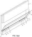
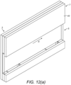
- the face panel 43 of the movable body 7 is slid in the second direction Y, here upwardly, which causes the slider 41 to be moved in the second direction Y from the intermediate position to an open position, in which the movable body 7 is latched open and the display panel 33 of the display section 5 is disengaged from the face panel 43 of the movable body 7, allowing the display section 5 to be opened for removal and replacement.
- the first engagement elements 20 of the main body 3 are received in the recesses 65 in the slider 41 of the movable body 7, and the detents 62 of the second engagement elements 52 of the slider 41 engage the detents 23 of the second engagement elements 22 of the main body 3 and latch the slider 41, and hence the movable body 7, in the open position.
- the display section 5 can be opened to allow for removal and/or replacement of at least part thereof, as illustrated in Figures 9(a) and (b) .
- the display sheet 31, which bears information, is removed and/or replaced.
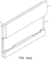
- the face panel 43 of the movable body 7 is slid in the second direction Y, here downwardly, which causes the slider 41 to be moved in the second direction Y from the open position to the intermediate position, in which the detents 62 of the second engagement elements 52 of the slider 41 are disengaged from the detents 23 of the second engagement elements 22 of the main body 3 and the first engagement elements 20 of the main body 3 are withdrawn from the recesses 65 in the slider 41 of the movable body 7.
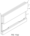
- the face panel 43 of the movable body 7 is slid in the first direction X, here laterally to the left, which causes the slider 41 to be moved in the first direction X from the intermediate position to the locked position, in which the detents 61 of the first engagement elements 51 of the slider 41 are engaged with the detents 21 of the first engagement elements 20 of the main body 3.
Landscapes
- Physics & Mathematics (AREA)
- General Physics & Mathematics (AREA)
- Engineering & Computer Science (AREA)
- Theoretical Computer Science (AREA)
- Displays For Variable Information Using Movable Means (AREA)
Claims (17)
- Anzeigeschild, umfassend:einen Hauptkörper (3);einen Anzeigeabschnitt (5); undeinen beweglichen Körper (7), der in Bezug auf den Hauptkörper (3) beweglich ist und so konfiguriert ist, dass er für eine Verriegelung und Freigabe des Anzeigeabschnitts (5) sorgt, um die Entfernung und/oder den Austausch von mindestens einem Teil des Anzeigeabschnitts (5) zu ermöglichen;wobei der Hauptkörper (3) einen Hohlraum (17) aufweist und der bewegliche Körper (7) einen Schieber (41) umfasst, der in dem Hohlraum (17) des Hauptkörpers (3) verschiebbar angeordnet ist,dadurch gekennzeichnet,dass der Hauptkörper mindestens ein erstes Eingriffselement (20) aufweist,der Schieber (41) mindestens eine Aussparung (65) aufweist, wobei die mindestens eine Aussparung (65) eine Breite hat, die größer ist als die Breite des mindestens einen ersten Eingriffselements (20) des Hauptkörpers (3), so dass, wenn der Schieber (41) in eine erste Richtung bewegt wird, die mindestens eine Aussparung (65) in dem Schieber (41) mit dem mindestens einen ersten Eingriffselement (20) des Hauptkörpers (3) ausgerichtet werden kann, wodurch der bewegliche Körper (7) in eine zweite Richtung orthogonal zu der ersten Richtung bewegt werden kann, wobei das mindestens eine erste Eingriffselement (20) des Hauptkörpers (3) in der mindestens einen Aussparung (65) in dem Schieber (4) aufgenommen wird.
- Schild nach Anspruch 1, wobei der Hauptkörper (3) aus Platten oder Paneelen gebildet ist.
- Schild nach Anspruch 1 oder 2, wobei der Hauptkörper (3) einen hinteren Abschnitt (8), der an einer Wand oder einer anderen Gebäudestruktur befestigt werden kann, und einen Eingriffsabschnitt (10) umfasst, mit dem der Anzeigeabschnitt (5) in Eingriff gebracht wird, wobei der Eingriffsabschnitt (10) ein Eingriffselement (14), das mindestens eine Aussparung zur Aufnahme mindestens eines Merkmals des Anzeigeabschnitts (5) enthält, und eine Frontplatte (16) umfasst.
- Schild nach Anspruch 3, wobei das Eingriffselement (14) an einer Vorderseite des hinteren Abschnitts (8) angebracht ist und die Frontplatte (16) an dem Eingriffselement (14) angebracht ist.
- Schild nach irgendeinem der vorhergehenden Ansprüche, wobei der Hohlraum (17) ein längliches Profil aufweist.
- Schild nach irgendeinem der vorhergehenden Ansprüche, wobei der Hauptkörper (3) und der Schieber (41) des beweglichen Körpers (7) jeweils mindestens ein erstes Eingriffselement (20) aufweisen und die ersten Eingriffselemente (20) in Eingriff stehen, wenn sich der bewegliche Körper (7) in der geschlossenen Position befindet, um den beweglichen Körper (7) in seiner Position zu verriegeln.
- Schild nach Anspruch 6, wobei die ersten Eingriffselemente (20) jeweils eine Arretierung (21) aufweisen und die Arretierungen (21) unverlierbar in Eingriff sind, wenn sich der bewegliche Körper (7) in der geschlossenen Position befindet.
- Schild nach Anspruch 6, wobei das mindestens eine erste Eingriffselement (20) des Hauptkörpers (3) an einer Längsseite (18) des Hohlraums (17) angeordnet ist und die andere Längsseite (18) des Hohlraums (17) eine Gleitfläche definiert, auf der der Schieber (41) des beweglichen Körpers (7) verschiebbar ist.
- Schild nach irgendeinem der Ansprüche 6, 7 oder 8, wobei das mindestens eine erste Eingriffselement (20) des Hauptkörpers (3) und/oder des Schiebers (41) des beweglichen Körpers (7) ein elastisch vorgespanntes Element ist.
- Schild nach irgendeinem der Ansprüche 6 bis 9, wobei der Hauptkörper (3) und der Schieber (41) des beweglichen Körpers (7) jeweils eine Vielzahl von ersten Eingriffselementen (20) aufweisen, die in einem Abstand zueinander angeordnet sind.
- Schild nach irgendeinem der Ansprüche 6 bis 10, wobei der Hauptkörper (3) und der Schieber (41) des beweglichen Körpers (7) jeweils mindestens ein zweites Eingriffselement (22) aufweisen, und die zweiten Eingriffselemente (22) in Eingriff stehen, wenn sich der bewegliche Körper (7) in der offenen Position befindet, um den beweglichen Körper (7) in der offenen Position zu verriegeln, wobei optional die zweiten Eingriffselemente (22) jeweils eine Arretierung (23) aufweisen und die Arretierungen (23) unverlierbar in Eingriff stehen, wenn sich der bewegliche Körper (7) in der offenen Position befindet, wobei optional die zweiten Eingriffselemente (22) an benachbarten Enden des Hohlraums (17) des Hauptkörpers (3) und des Schiebers (41) des beweglichen Körpers (7) angeordnet sind.
- Schild nach Anspruch 11, wobei das mindestens eine zweite Eingriffselement (22) des Hauptkörpers (3) und/oder des Gleiters (41) des beweglichen Körpers (7) ein elastisch vorgespanntes Element ist.
- Schild nach Anspruch 11 oder 12, wobei der Hauptkörper (3) und der Schieber (4) des beweglichen Körpers (7) jeweils eine Vielzahl von zweiten Eingriffselementen (22) aufweisen.
- Schild nach irgendeinem der vorhergehenden Ansprüche, wobei das mindestens eine Eingriffselement des Hauptkörpers (3) oder des Schiebers (41) des beweglichen Körpers (7) einen Vorsprung aufweist, der sich in die zweite Richtung erstreckt, und der andere Hauptkörper (7) des Schiebers (41) des beweglichen Körpers (7) mindestens eine Ausnehmung aufweist, die den Vorsprung des Hauptkörpers (3) oder des Schiebers (41) des beweglichen Körpers (7) nur dann aufnimmt, wenn der Schieber (41) des beweglichen Körpers (7) aus der Zwischenposition in die zweite Richtung bewegt wird, wodurch eine Bewegung des Schiebers (41) des beweglichen Körpers (7) in der zweiten Richtung verhindert wird, wenn sich der Schieber (41) des beweglichen Körpers (7) in einer anderen als der Zwischenposition befindet, wobei optional die mindestens eine Ausnehmung in dem anderen des Hauptkörpers (3) des Schiebers (41) des beweglichen Körpers (7) neben dem mindestens einen ersten Eingriffselement in dem einen des Hauptkörpers (3) des Schiebers (4) des beweglichen Körpers (7) angeordnet ist, wobei optional der andere des Hauptkörpers (3) des Schiebers (41) des beweglichen Körpers (7) eine Vielzahl von Ausnehmungen enthält, die in beabstandeter, entgegengesetzter Beziehung zu den ersten Eingriffselementen an dem einen des Hauptkörpers (3) und des Schiebers (41) des beweglichen Körpers (7) angeordnet sind.
- Schild nach irgendeinem der vorhergehenden Ansprüche, wobei der bewegliche Körper (7) ferner eine Frontplatte (43) umfasst, die an dem Schieber (41) desselben angebracht ist, so dass der Schieber (41) durch Bewegung der Frontplatte (43) bewegt wird, wobei die Frontplatte (43) des beweglichen Körpers (7) optional ein oberer Kopf ist, wobei der Hauptkörper (3) optional einen hinteren Abschnitt und einen Abstandshalter umfasst, der an einer vorderen Fläche des hinteren Abschnitts angeordnet ist und die Frontplatte (43) des beweglichen Körpers (7) von dem hinteren Abschnitt beabstandet, wobei optional der Abstandshalter und der Eingriffsabschnitt eine Aussparung dazwischen definieren, in der der Anzeigeabschnitt (5) angeordnet ist, wobei optional der Abstandshalter eine Öffnung enthält, die so geformt ist, dass der Schieber (41) des beweglichen Körpers (7) in dem Hohlraum des Hauptkörpers (3) festgehalten wird, aber eine Bewegung des beweglichen Körpers (7) in eine erste und eine zweite Richtung ermöglicht.
- Schild nach irgendeinem der vorhergehenden Ansprüche, wobei der Anzeigeabschnitt (5) einen Anzeigeeinsatz, der Informationen trägt, und eine Anzeigetafel (33) umfasst, die zumindest teilweise transparent ist und den Anzeigeeinsatz (31) abdeckt, um diesen zu umschließen, wobei die Abdecktafel in eine offene Position bewegt werden kann, wenn sich der bewegliche Körper (7) in der offenen Position befindet, um die Entnahme und/oder das Auswechseln des Anzeigeeinsatzes (31) zu ermöglichen, wobei die Anzeigetafel (33) optional am Hauptkörper (3) angelenkt werden kann.
- Schild nach irgendeinem der vorhergehenden Ansprüche, wobei der Anzeigeabschnitt (5) eine Anzeigetafel (33) umfasst, die Informationen trägt und in eine offene Position bewegt werden kann, wenn sich der bewegliche Körper (7) in der offenen Position befindet, so dass die Anzeigetafel (33) entfernt und/oder ausgetauscht werden kann.
Applications Claiming Priority (2)
| Application Number | Priority Date | Filing Date | Title |
|---|---|---|---|
| GB1619963.0A GB2558875B (en) | 2016-11-25 | 2016-11-25 | Display sign |
| PCT/EP2017/079965 WO2018095927A1 (en) | 2016-11-25 | 2017-11-21 | Display sign |
Publications (2)
| Publication Number | Publication Date |
|---|---|
| EP3545512A1 EP3545512A1 (de) | 2019-10-02 |
| EP3545512B1 true EP3545512B1 (de) | 2024-11-06 |
Family
ID=58073348
Family Applications (1)
| Application Number | Title | Priority Date | Filing Date |
|---|---|---|---|
| EP17801048.4A Active EP3545512B1 (de) | 2016-11-25 | 2017-11-21 | Anzeigeschild |
Country Status (5)
| Country | Link |
|---|---|
| US (1) | US10878727B2 (de) |
| EP (1) | EP3545512B1 (de) |
| DK (1) | DK3545512T3 (de) |
| GB (1) | GB2558875B (de) |
| WO (1) | WO2018095927A1 (de) |
Families Citing this family (2)
| Publication number | Priority date | Publication date | Assignee | Title |
|---|---|---|---|---|
| US10710518B2 (en) * | 2017-09-08 | 2020-07-14 | II Ronald Urbanczyk | License plate bracket |
| AT524734A1 (de) | 2021-02-10 | 2022-08-15 | Manfred Seeleitner | Anzeigetafel, insbesondere Türschild |
Family Cites Families (20)
| Publication number | Priority date | Publication date | Assignee | Title |
|---|---|---|---|---|
| GB187079A (en) * | 1921-08-19 | 1922-10-19 | Joseph Bell Bingham | Improvements relating to changeable signs, and the like |
| FR2284156A1 (fr) * | 1974-12-31 | 1976-04-02 | Cuadrado Roger | Panneau d'identification a signes interchangeables |
| US5189822A (en) * | 1990-08-24 | 1993-03-02 | Carsonite International | Tamper resistant sign |
| US5343646A (en) * | 1992-10-23 | 1994-09-06 | Apco Graphics, Inc. | Sign apparatus with improved mounting of message panels |
| DE4336906C2 (de) * | 1993-10-28 | 2000-04-27 | Thomas Walz | Vorrichtung zur Aufnahme eines Tafelelements |
| US5657566A (en) * | 1995-07-28 | 1997-08-19 | Key; Jeffrey M. | Rapid mount advertising panels |
| US7383654B2 (en) * | 1997-04-28 | 2008-06-10 | Exclusive Door Handles, Inc. | Door handle with interchangeable graphic display |
| DE29711920U1 (de) * | 1997-07-07 | 1998-07-09 | mouldtec Kunststoff GmbH, 87600 Kaufbeuren | Kennzeichenträger für Schilder |
| US6618974B2 (en) * | 2000-04-12 | 2003-09-16 | David E. Szalay | Message display apparatus |
| DE10214402B4 (de) * | 2002-03-30 | 2006-02-02 | Walz Gmbh & Co | Vorrichtung zur Aufnahme eines Tafelelements |
| EP1711929B1 (de) * | 2004-02-02 | 2008-11-05 | Durable Hunke & Jochheim GmbH & Co. KG. | Schild, insbesondere informationsschild |
| US7412791B2 (en) * | 2004-12-20 | 2008-08-19 | Lsi Industries, Inc. | Adjustable menu panel |
| US7428793B2 (en) * | 2005-08-19 | 2008-09-30 | Dwyer Michael H | Personalized wooden items and methods for fabricating same |
| US8808006B2 (en) * | 2010-12-02 | 2014-08-19 | ID Signsystems, Inc. | Multiplanar display system |
| US8733000B1 (en) * | 2012-06-01 | 2014-05-27 | Sanjay Thakker | Advertisement display and method of use |
| US8333027B1 (en) * | 2012-07-09 | 2012-12-18 | Zenith Innovation, Llc | Interchangeable address signage system |
| US8650785B1 (en) * | 2012-12-12 | 2014-02-18 | Target Brands, Inc. | Sign holder assembly and associated methods |
| US10223941B2 (en) * | 2015-09-24 | 2019-03-05 | Michael Joseph Anzalone | Nameplates and locking assemblies thereof |
| US9747818B1 (en) * | 2016-11-22 | 2017-08-29 | System 2/90, Inc. | Sign holder system |
| US10477987B2 (en) * | 2018-03-21 | 2019-11-19 | K-International, Inc. | Advertising panel and method for mounting to a surface |
-
2016
- 2016-11-25 GB GB1619963.0A patent/GB2558875B/en active Active
-
2017
- 2017-11-21 EP EP17801048.4A patent/EP3545512B1/de active Active
- 2017-11-21 WO PCT/EP2017/079965 patent/WO2018095927A1/en not_active Ceased
- 2017-11-21 US US16/463,696 patent/US10878727B2/en active Active
- 2017-11-21 DK DK17801048.4T patent/DK3545512T3/da active
Also Published As
| Publication number | Publication date |
|---|---|
| GB201619963D0 (en) | 2017-01-11 |
| US10878727B2 (en) | 2020-12-29 |
| GB2558875B (en) | 2022-01-12 |
| WO2018095927A1 (en) | 2018-05-31 |
| US20190287432A1 (en) | 2019-09-19 |
| GB2558875A (en) | 2018-07-25 |
| DK3545512T3 (da) | 2025-02-03 |
| EP3545512A1 (de) | 2019-10-02 |
Similar Documents
| Publication | Publication Date | Title |
|---|---|---|
| US8127478B2 (en) | Messaging sign having plates and reversible locking system | |
| EP3545512B1 (de) | Anzeigeschild | |
| EP3029658A1 (de) | Schautafel, verfahren zur preisauszeichnung sowie in einem kraftfahrzeug angeordnete schautafel | |
| DE69212607T2 (de) | Photoalbum und dessen herstellungsverfahren | |
| US20180015773A1 (en) | Expandable folder | |
| US10586477B2 (en) | System and associated methods for advertising from a traffic signal control cabinet | |
| US7694446B1 (en) | Modular picture frame apparatus | |
| US20210188197A1 (en) | Placard holder | |
| US9424763B2 (en) | Messaging sign having a reversible fastening system for moveable display articles | |
| US7573702B2 (en) | Display device | |
| US8347536B2 (en) | Display device | |
| DE202012007209U1 (de) | Aufklappbare Schutzhülle für elektronische Geräte mit Faltdeckel und Standfuß | |
| US20090167125A1 (en) | Magnetic Panel Systems for Decorating Metallic Locker Interior Walls | |
| US20170066281A1 (en) | Writing board | |
| JP5580033B2 (ja) | 棚用仕切具 | |
| KR101530958B1 (ko) | 시트 교체식 광고판 | |
| AU2016100276A4 (en) | A server rack blank | |
| CN212479799U (zh) | 一种门片联动卡子以及组合柜 | |
| EP1249816B1 (de) | Gesicherte Vorrichtung für ein Anzeigesystem | |
| AU2016202248B2 (en) | Writing board | |
| KR200326445Y1 (ko) | 표시판 조립체 | |
| AU2015101202A4 (en) | Panel mounting system | |
| EP1717779A1 (de) | Selbsthaltende Anzeigeeinrichtung mit auswechselbaren Beschriftungsfeldern und dazugehöriger Box deren Oberfläche für diese Anwendung adaptiert ist | |
| DE202010011896U1 (de) | Vorratsregal mit zusammensetzbaren Wandelementen | |
| AU2013203377A1 (en) | Display Device |
Legal Events
| Date | Code | Title | Description |
|---|---|---|---|
| STAA | Information on the status of an ep patent application or granted ep patent |
Free format text: STATUS: UNKNOWN |
|
| STAA | Information on the status of an ep patent application or granted ep patent |
Free format text: STATUS: THE INTERNATIONAL PUBLICATION HAS BEEN MADE |
|
| PUAI | Public reference made under article 153(3) epc to a published international application that has entered the european phase |
Free format text: ORIGINAL CODE: 0009012 |
|
| STAA | Information on the status of an ep patent application or granted ep patent |
Free format text: STATUS: REQUEST FOR EXAMINATION WAS MADE |
|
| 17P | Request for examination filed |
Effective date: 20190625 |
|
| AK | Designated contracting states |
Kind code of ref document: A1 Designated state(s): AL AT BE BG CH CY CZ DE DK EE ES FI FR GB GR HR HU IE IS IT LI LT LU LV MC MK MT NL NO PL PT RO RS SE SI SK SM TR |
|
| AX | Request for extension of the european patent |
Extension state: BA ME |
|
| DAV | Request for validation of the european patent (deleted) | ||
| DAX | Request for extension of the european patent (deleted) | ||
| REG | Reference to a national code |
Ref country code: HK Ref legal event code: DE Ref document number: 40007237 Country of ref document: HK |
|
| STAA | Information on the status of an ep patent application or granted ep patent |
Free format text: STATUS: EXAMINATION IS IN PROGRESS |
|
| 17Q | First examination report despatched |
Effective date: 20200727 |
|
| GRAP | Despatch of communication of intention to grant a patent |
Free format text: ORIGINAL CODE: EPIDOSNIGR1 |
|
| STAA | Information on the status of an ep patent application or granted ep patent |
Free format text: STATUS: GRANT OF PATENT IS INTENDED |
|
| INTG | Intention to grant announced |
Effective date: 20240603 |
|
| GRAS | Grant fee paid |
Free format text: ORIGINAL CODE: EPIDOSNIGR3 |
|
| GRAA | (expected) grant |
Free format text: ORIGINAL CODE: 0009210 |
|
| STAA | Information on the status of an ep patent application or granted ep patent |
Free format text: STATUS: THE PATENT HAS BEEN GRANTED |
|
| AK | Designated contracting states |
Kind code of ref document: B1 Designated state(s): AL AT BE BG CH CY CZ DE DK EE ES FI FR GB GR HR HU IE IS IT LI LT LU LV MC MK MT NL NO PL PT RO RS SE SI SK SM TR |
|
| REG | Reference to a national code |
Ref country code: GB Ref legal event code: FG4D |
|
| REG | Reference to a national code |
Ref country code: CH Ref legal event code: EP |
|
| REG | Reference to a national code |
Ref country code: DE Ref legal event code: R096 Ref document number: 602017085959 Country of ref document: DE |
|
| REG | Reference to a national code |
Ref country code: IE Ref legal event code: FG4D |
|
| REG | Reference to a national code |
Ref country code: DK Ref legal event code: T3 Effective date: 20250128 |
|
| REG | Reference to a national code |
Ref country code: LT Ref legal event code: MG9D |
|
| REG | Reference to a national code |
Ref country code: NL Ref legal event code: MP Effective date: 20241106 |
|
| PG25 | Lapsed in a contracting state [announced via postgrant information from national office to epo] |
Ref country code: IS Free format text: LAPSE BECAUSE OF FAILURE TO SUBMIT A TRANSLATION OF THE DESCRIPTION OR TO PAY THE FEE WITHIN THE PRESCRIBED TIME-LIMIT Effective date: 20250306 Ref country code: HR Free format text: LAPSE BECAUSE OF FAILURE TO SUBMIT A TRANSLATION OF THE DESCRIPTION OR TO PAY THE FEE WITHIN THE PRESCRIBED TIME-LIMIT Effective date: 20241106 Ref country code: PT Free format text: LAPSE BECAUSE OF FAILURE TO SUBMIT A TRANSLATION OF THE DESCRIPTION OR TO PAY THE FEE WITHIN THE PRESCRIBED TIME-LIMIT Effective date: 20250306 |
|
| PG25 | Lapsed in a contracting state [announced via postgrant information from national office to epo] |
Ref country code: NL Free format text: LAPSE BECAUSE OF FAILURE TO SUBMIT A TRANSLATION OF THE DESCRIPTION OR TO PAY THE FEE WITHIN THE PRESCRIBED TIME-LIMIT Effective date: 20241106 Ref country code: FI Free format text: LAPSE BECAUSE OF FAILURE TO SUBMIT A TRANSLATION OF THE DESCRIPTION OR TO PAY THE FEE WITHIN THE PRESCRIBED TIME-LIMIT Effective date: 20241106 |
|
| PG25 | Lapsed in a contracting state [announced via postgrant information from national office to epo] |
Ref country code: BG Free format text: LAPSE BECAUSE OF FAILURE TO SUBMIT A TRANSLATION OF THE DESCRIPTION OR TO PAY THE FEE WITHIN THE PRESCRIBED TIME-LIMIT Effective date: 20241106 |
|
| PG25 | Lapsed in a contracting state [announced via postgrant information from national office to epo] |
Ref country code: ES Free format text: LAPSE BECAUSE OF FAILURE TO SUBMIT A TRANSLATION OF THE DESCRIPTION OR TO PAY THE FEE WITHIN THE PRESCRIBED TIME-LIMIT Effective date: 20241106 |
|
| PG25 | Lapsed in a contracting state [announced via postgrant information from national office to epo] |
Ref country code: NO Free format text: LAPSE BECAUSE OF FAILURE TO SUBMIT A TRANSLATION OF THE DESCRIPTION OR TO PAY THE FEE WITHIN THE PRESCRIBED TIME-LIMIT Effective date: 20250206 |
|
| PG25 | Lapsed in a contracting state [announced via postgrant information from national office to epo] |
Ref country code: GR Free format text: LAPSE BECAUSE OF FAILURE TO SUBMIT A TRANSLATION OF THE DESCRIPTION OR TO PAY THE FEE WITHIN THE PRESCRIBED TIME-LIMIT Effective date: 20250207 Ref country code: LV Free format text: LAPSE BECAUSE OF FAILURE TO SUBMIT A TRANSLATION OF THE DESCRIPTION OR TO PAY THE FEE WITHIN THE PRESCRIBED TIME-LIMIT Effective date: 20241106 |
|
| PG25 | Lapsed in a contracting state [announced via postgrant information from national office to epo] |
Ref country code: PL Free format text: LAPSE BECAUSE OF FAILURE TO SUBMIT A TRANSLATION OF THE DESCRIPTION OR TO PAY THE FEE WITHIN THE PRESCRIBED TIME-LIMIT Effective date: 20241106 |
|
| PG25 | Lapsed in a contracting state [announced via postgrant information from national office to epo] |
Ref country code: RS Free format text: LAPSE BECAUSE OF FAILURE TO SUBMIT A TRANSLATION OF THE DESCRIPTION OR TO PAY THE FEE WITHIN THE PRESCRIBED TIME-LIMIT Effective date: 20250206 |
|
| REG | Reference to a national code |
Ref country code: CH Ref legal event code: PL |
|
| PG25 | Lapsed in a contracting state [announced via postgrant information from national office to epo] |
Ref country code: SM Free format text: LAPSE BECAUSE OF FAILURE TO SUBMIT A TRANSLATION OF THE DESCRIPTION OR TO PAY THE FEE WITHIN THE PRESCRIBED TIME-LIMIT Effective date: 20241106 |
|
| PG25 | Lapsed in a contracting state [announced via postgrant information from national office to epo] |
Ref country code: LU Free format text: LAPSE BECAUSE OF NON-PAYMENT OF DUE FEES Effective date: 20241121 |
|
| REG | Reference to a national code |
Ref country code: CH Ref legal event code: PL |
|
| PG25 | Lapsed in a contracting state [announced via postgrant information from national office to epo] |
Ref country code: EE Free format text: LAPSE BECAUSE OF FAILURE TO SUBMIT A TRANSLATION OF THE DESCRIPTION OR TO PAY THE FEE WITHIN THE PRESCRIBED TIME-LIMIT Effective date: 20241106 |
|
| PG25 | Lapsed in a contracting state [announced via postgrant information from national office to epo] |
Ref country code: CH Free format text: LAPSE BECAUSE OF NON-PAYMENT OF DUE FEES Effective date: 20241130 |
|
| PG25 | Lapsed in a contracting state [announced via postgrant information from national office to epo] |
Ref country code: RO Free format text: LAPSE BECAUSE OF FAILURE TO SUBMIT A TRANSLATION OF THE DESCRIPTION OR TO PAY THE FEE WITHIN THE PRESCRIBED TIME-LIMIT Effective date: 20241106 |
|
| PG25 | Lapsed in a contracting state [announced via postgrant information from national office to epo] |
Ref country code: SK Free format text: LAPSE BECAUSE OF FAILURE TO SUBMIT A TRANSLATION OF THE DESCRIPTION OR TO PAY THE FEE WITHIN THE PRESCRIBED TIME-LIMIT Effective date: 20241106 |
|
| PG25 | Lapsed in a contracting state [announced via postgrant information from national office to epo] |
Ref country code: CZ Free format text: LAPSE BECAUSE OF FAILURE TO SUBMIT A TRANSLATION OF THE DESCRIPTION OR TO PAY THE FEE WITHIN THE PRESCRIBED TIME-LIMIT Effective date: 20241106 |
|
| PG25 | Lapsed in a contracting state [announced via postgrant information from national office to epo] |
Ref country code: IT Free format text: LAPSE BECAUSE OF FAILURE TO SUBMIT A TRANSLATION OF THE DESCRIPTION OR TO PAY THE FEE WITHIN THE PRESCRIBED TIME-LIMIT Effective date: 20241106 |
|
| REG | Reference to a national code |
Ref country code: DE Ref legal event code: R097 Ref document number: 602017085959 Country of ref document: DE |
|
| REG | Reference to a national code |
Ref country code: BE Ref legal event code: MM Effective date: 20241130 |
|
| PG25 | Lapsed in a contracting state [announced via postgrant information from national office to epo] |
Ref country code: SE Free format text: LAPSE BECAUSE OF FAILURE TO SUBMIT A TRANSLATION OF THE DESCRIPTION OR TO PAY THE FEE WITHIN THE PRESCRIBED TIME-LIMIT Effective date: 20241106 |
|
| PLBE | No opposition filed within time limit |
Free format text: ORIGINAL CODE: 0009261 |
|
| STAA | Information on the status of an ep patent application or granted ep patent |
Free format text: STATUS: NO OPPOSITION FILED WITHIN TIME LIMIT |
|
| PG25 | Lapsed in a contracting state [announced via postgrant information from national office to epo] |
Ref country code: MC Free format text: LAPSE BECAUSE OF FAILURE TO SUBMIT A TRANSLATION OF THE DESCRIPTION OR TO PAY THE FEE WITHIN THE PRESCRIBED TIME-LIMIT Effective date: 20241106 |
|
| 26N | No opposition filed |
Effective date: 20250807 |
|
| PG25 | Lapsed in a contracting state [announced via postgrant information from national office to epo] |
Ref country code: BE Free format text: LAPSE BECAUSE OF NON-PAYMENT OF DUE FEES Effective date: 20241130 |
|
| PGFP | Annual fee paid to national office [announced via postgrant information from national office to epo] |
Ref country code: DE Payment date: 20251119 Year of fee payment: 9 |
|
| PGFP | Annual fee paid to national office [announced via postgrant information from national office to epo] |
Ref country code: GB Payment date: 20251013 Year of fee payment: 9 |
|
| PGFP | Annual fee paid to national office [announced via postgrant information from national office to epo] |
Ref country code: AT Payment date: 20251120 Year of fee payment: 9 |
|
| PGFP | Annual fee paid to national office [announced via postgrant information from national office to epo] |
Ref country code: DK Payment date: 20251125 Year of fee payment: 9 |
|
| PGFP | Annual fee paid to national office [announced via postgrant information from national office to epo] |
Ref country code: FR Payment date: 20251126 Year of fee payment: 9 |
|
| PGFP | Annual fee paid to national office [announced via postgrant information from national office to epo] |
Ref country code: IE Payment date: 20251013 Year of fee payment: 9 |