EP3545231B1 - Abdeckung für led-leuchten - Google Patents
Abdeckung für led-leuchten Download PDFInfo
- Publication number
- EP3545231B1 EP3545231B1 EP17800522.9A EP17800522A EP3545231B1 EP 3545231 B1 EP3545231 B1 EP 3545231B1 EP 17800522 A EP17800522 A EP 17800522A EP 3545231 B1 EP3545231 B1 EP 3545231B1
- Authority
- EP
- European Patent Office
- Prior art keywords
- light
- endpoint
- rounded corner
- cover
- section
- Prior art date
- Legal status (The legal status is an assumption and is not a legal conclusion. Google has not performed a legal analysis and makes no representation as to the accuracy of the status listed.)
- Active
Links
Images


Classifications
-
- F—MECHANICAL ENGINEERING; LIGHTING; HEATING; WEAPONS; BLASTING
- F21—LIGHTING
- F21V—FUNCTIONAL FEATURES OR DETAILS OF LIGHTING DEVICES OR SYSTEMS THEREOF; STRUCTURAL COMBINATIONS OF LIGHTING DEVICES WITH OTHER ARTICLES, NOT OTHERWISE PROVIDED FOR
- F21V3/00—Globes; Bowls; Cover glasses
- F21V3/02—Globes; Bowls; Cover glasses characterised by the shape
-
- F—MECHANICAL ENGINEERING; LIGHTING; HEATING; WEAPONS; BLASTING
- F21—LIGHTING
- F21K—NON-ELECTRIC LIGHT SOURCES USING LUMINESCENCE; LIGHT SOURCES USING ELECTROCHEMILUMINESCENCE; LIGHT SOURCES USING CHARGES OF COMBUSTIBLE MATERIAL; LIGHT SOURCES USING SEMICONDUCTOR DEVICES AS LIGHT-GENERATING ELEMENTS; LIGHT SOURCES NOT OTHERWISE PROVIDED FOR
- F21K9/00—Light sources using semiconductor devices as light-generating elements, e.g. using light-emitting diodes [LED] or lasers
- F21K9/20—Light sources comprising attachment means
- F21K9/27—Retrofit light sources for lighting devices with two fittings for each light source, e.g. for substitution of fluorescent tubes
-
- F—MECHANICAL ENGINEERING; LIGHTING; HEATING; WEAPONS; BLASTING
- F21—LIGHTING
- F21Y—INDEXING SCHEME ASSOCIATED WITH SUBCLASSES F21K, F21L, F21S and F21V, RELATING TO THE FORM OR THE KIND OF THE LIGHT SOURCES OR OF THE COLOUR OF THE LIGHT EMITTED
- F21Y2103/00—Elongate light sources, e.g. fluorescent tubes
- F21Y2103/10—Elongate light sources, e.g. fluorescent tubes comprising a linear array of point-like light-generating elements
-
- F—MECHANICAL ENGINEERING; LIGHTING; HEATING; WEAPONS; BLASTING
- F21—LIGHTING
- F21Y—INDEXING SCHEME ASSOCIATED WITH SUBCLASSES F21K, F21L, F21S and F21V, RELATING TO THE FORM OR THE KIND OF THE LIGHT SOURCES OR OF THE COLOUR OF THE LIGHT EMITTED
- F21Y2115/00—Light-generating elements of semiconductor light sources
- F21Y2115/10—Light-emitting diodes [LED]
Definitions
- the present invention relates to a luminaire housing comprising a light chamber delimited by a light-transmissive cover comprising at least one rounded corner section in between two further sections.
- the present invention further relates to a luminaire comprising such a luminaire housing.
- the present invention further relates to a method of designing such a luminaire housing.
- the present invention further relates to a method of manufacturing such a luminaire housing.
- Solid state lighting e.g. LED lighting
- previous generation lighting e.g. incandescent or fluorescent lighting
- new luminaires are being designed with SSL elements in mind, such that the optical performance of the luminaire is tailored to the SSL elements.
- luminaires designed for previous generation lighting are being reused with SSL elements, for example by replacing the previous generation lighting. Consequently, the luminaire may no longer exhibit the desired optical performance due to the fact that SSL elements have a distinctly different optical characteristic compared to previous generation light sources such as (tubular) incandescent or fluorescent lighting.
- waterproof luminaires such as the Philips Pacific Performer WT360C typically comprise a transparent waterproof housing including a cover, which may be removable in order to provide access to the interior of the luminaire, e.g. to replace the light source therein.
- a cover typically comprises rounded corner sections for aesthetic, mechanical and/or optical reasons as well as for health and safety reasons, e.g. to prevent injury by sharp corners.
- FIG. 1 Such a prior art luminaire is schematically depicted in FIG. 1 , in which the elongate luminaire comprises a luminaire housing 10 including a base 20 and light-transmissive polycarbonate cover 30 having rounded corner sections 31 and linear (planar) sections 33.
- the cover 20 delimits an optical chamber 15 in which one or more fluorescent light tubes 25, e.g.
- T5 tubes are mounted in a mounting region within the optical chamber 15, e.g. in fitting brackets or the like.
- optical artefacts in its luminous output can be clearly detected, in particular when the SSL elements are small relative to the diameter of the tubular body.
- Such optical artefacts include non-uniformity in the luminous distribution over the cross-section of the luminaire both in terms of colour and intensity, e.g. dark and bright lines as well as colour effects that become visible on the surfaces onto which the luminous distribution of such a luminaire is projected. Further optical artefacts may be caused by extrusion stripes in the extruded polycarbonate cover 30.
- CN203421614U discloses an LED lamp shade that is hollow and is in a shape of a long square column.
- the inner wall of the bottom of the lamp shade is a curved surface
- the inner wall surfaces of a first side edge and a second side edge which are opposite to each other of the inner wall of the side edge of the lamp shade are irregular saw-toothed refraction structures.
- the angles of saw teeth of the inner wall surfaces of the first side edge are increased gradually from the top of the inner side to the bottom of the inner side
- the angles of the saw teeth of the inner wall surfaces of the second side edge are increased gradually from the top of the inner side to the bottom of the inner side in order to achieve an even luminous distribution.
- the present invention seeks to provide a luminaire housing comprising a light chamber delimited by a light-transmissive cover comprising at least one rounded corner section in between two further linear, planar sections for which such optical artefacts have been reduced.
- the present invention further seeks to provide a luminaire comprising such a luminaire housing.
- the present invention further seeks to provide a method of designing such a luminaire housing.
- the present invention further seeks to provide a method of manufacturing such a luminaire housing.
- a luminaire housing formed by a cover or by a cover cooperating with a base and the luminaire housing comprising a light chamber at least partially delimited by a light-transmissive wall with a thickness Tw of said cover comprising at least one rounded corner section in between two further, linear, planar sections, said light chamber comprising a mounting region for mounting at least one solid state lighting element, wherein the rounded corner section has an inner surface having opposing inner endpoints and an outer surface having opposing outer endpoints, wherein a plane under critical angle ⁇ c at the inner surface at an inner endpoint does not extend through the outer surface of the rounded corner section, such that no ray of light emitted by the at least one solid state lighting element entering the light-transmissive cover via the further inner surface of the further section exits the light-transmissive cover from the outer surface of the rounded corner section wherein the light-transmissive cover comprises a pair of said rounded corner sections, wherein one of said further sections is located in between the pair of
- PMMA PolyMethylMethAcrylate
- PC PolyCarbonate
- n1 air n2 cover n1/n2 crit angle 1 1.3 0.769231 50.31037 1 1.5 0.666667 41.83152 1 1.7 0.588235 36.05015 1 2 0.5 30.01522 1 2.2 0.454545 27.0494
- the present inventors have realized that a deterioration in the optical performance of a luminaire comprising rounded corner sections upon replacement of its original light source with SSL equivalents is caused by the reduction in form factor associated with such replacement.
- the rounded corner section may be considered small relative to the overall size of the original light source, e.g. a (tubular) light bulb or the like, this consideration no longer holds when replacing the original light source with SSL elements, e.g. LEDs, which may be approximated as point light sources.
- This causes boundary artefacts at the boundary between the rounded corner section and the further sections, e.g.
- Said divergence can even be further reduced when at the endpoints a tangent to the surface of the rounded corner section is parallel to a tangent to a proximal further inner surface of its proximal further section, i.e. both the inner and outer surface have a smooth transision between the further, linear, planar section and the rounded corner section, in other words said transition is without a discontinuity, such as a kink or step.
- the light-transmissive cover comprises a pair of said rounded corner sections, for example as rounded corners of a cover having a U-shaped cross-sectional profile.
- one of said further sections e.g. a (near-)planar section, may be located in between the pair of rounded corner sections.
- the luminaire housing might have the feature that the mounting region is outside an area range between the wall and at least one of said planes alongside its proximal further section of said wall for reduing the risk of uncontrolled stray light.
- the mounting region is outside an area range between the wall and at least one of said planes alongside its proximal further section of said wall for reduing the risk of uncontrolled stray light.
- the mounting region and the rounded corner section are elongated in parallel elongation directions.
- the luminaire housing may be an elongated housing such as a tubular housing including a cover with rounded corners.
- the light-transmissive cover may in some embodiments be transparent, which has the advantage that a directional luminous output may be produced having reduced optical artefacts compared to comparable prior art covers.
- a luminaire that includes the luminaire housing of any of the herein described embodiments and that further includes at least one solid state lighting element mounted in the mounting region.
- Such a luminaire benefits from exhibiting fewer optical artefacts due to the inventive design of the luminaire housing and the light-transmissive cover in particular.
- the outer endpoints of the outer spline may be correctly positioned by calculating a ray path through the light-transmissive cover for each ray based on an angle of incidence of said ray with said inner endpoint and the defined refractive index; and positioning the corresponding outer endpoint on said ray path. This ensures that these light rays define appropriate boundary conditions such that light rays entering a further section of the material of the light-transmissive cover cannot crossover into a curved corner section of the cover, thereby avoiding optical artefacts associated with such a crossover.
- the computer-implemented method further comprises receiving an adjustment of a curvature of the second spline; calculate a degree of convergence or divergence for light rays originating from the solid state light source at exiting the rounded corner section for said adjusted curvature; and accepting the curvature adjustment if said degree of convergence or divergence exhibits an improvement compared to light rays originating from the solid state light source at exiting the rounded corner section as defined by the second spline without said adjusted curvature.
- a further section e.g.
- the optical performance of the curved corner section may be further optimized by (iteratively) adjusting the curvature of the outer surface of the curved corner section represented by the second spline.
- This further may include determining a thickness across the rounded corner section including the adjustment to the curvature of the second spline; and rejecting said curvature adjustment if said thickness exceeds a design tolerance to ensure that light-transmissive cover design can still be manufactured within defined design or manufacturing tolerances.
- the curvature of the first spline is defined by a first vector associated with the first inner endpoint and a second vector associated with the second inner endpoint;
- each spline is tangential to the further section, e.g. a (near-)planar section, it connects to ensure desirable boundary conditions between this section and its connecting rounded corner section although small deviations from such a tangential arrangement may be tolerated.
- the further section e.g. a (near-)planar section
- a method of manufacturing a light-transmissive cover for a luminaire housing comprising manufacturing a mold for the light-transmissive cover using the design specification, including generating an output of a design specification of the light-transmissive cover including wall-thickness Tw, and relative positions of inner end points and proximal outer end points and the defined first and second splines as produced by the aforementioned computer-implemented method and manufacturing the light-transmissive cover with said mold to provide a light-transmissive cover with improved optical performance as explained above.
- the light-transmissive cover may be manufactured by extrusion or a moulding technique such as injection moulding, e.g. using a suitable polymer material such as polycarbonate, poly (methyl methacrylate) and poly ethylene terephthalate for example.
- a suitable polymer material such as polycarbonate, poly (methyl methacrylate) and poly ethylene terephthalate for example.
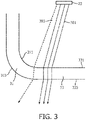
- FIG. 3 schematically depicts an aspect of a prior art light-transmissive cover 30 as depicted in FIG. 1 when equipped with SSL elements 23 as schematically depicted in FIG. 2 .
- FIG. 3 highlights a root cause of the optical artefacts that may occur in such a scenario.
- the light-transmissive cover 30 is typically designed using CAD software in which one of the inner surface 311 and the outer surface 313 of the curved corner section 31 is drawn after which an offset function in the CAD software is used to generate the other of the inner surface 311 and the outer surface 313, thereby generating opposing curved surfaces with a different radial distance (corresponding to a constant wall thickness of the cover 31) from a central point used to define these curved (arcuate) surfaces.
- the difference in radius between the inner surface 311 and the outer surface 313 is equal to the offset between the inner and outer walls of the cover.
- light rays 303 emitted by the SSL element 23 may enter the cover material via the inner surface 331 of a section 33, which may be a planar section in some embodiments or which may be slightly curved in some other embodiments, i.e. may be near-planar, but exit the cover 30 via the outer surface of the adjacent curved corner section 31, which causes the light rays 303 to diverge from light rays 301 that enter the cover material via the inner surface 331 of a section 33 and exit the cover 30 via the outer surface 333 of the section 33.
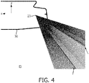
- FIG. 4 which depicts a simulated ray fan of such a cover arrangement (a cross-section of the cover 30 is schematically depicted), at the boundary between the further sections 33, e.g. planar sections or near-planar sections, and the rounded corner sections, bright lines in the luminous distribution generated with the SSL element 23 (here approximated by a point source) as indicated by the arrows appear in the ray fan, in which light rays are represented by black lines. It can be seen that the area between the arrows in FIG. 4 has fewer light rays, which is indicative of the aforementioned boundary-induced divergence.
- the luminaire housing 10 comprises an incandescent or fluorescent light source
- the light emitting area of such a light source is large relative to the distance between the light emitting area and the cover 30 such that imperfections in the shape of the tube are not visible, e.g. due to overlapping intensity peaks in case of multiple fluorescent tubes within the luminaire housing 10.
- the light emitting area of individual (square) SSL elements 23 typically is in the region of 0.2 ⁇ 0.2 mm to 1 ⁇ 1 mm, such that imperfections in the shape of the tube become visible in the luminous output of the luminaire.
- each SSL element 23 may be optically coupled to a diffuser to increase the etendue of the SSL element, thereby reducing the severity of the optical artefacts, or alternatively the light-transmissive cover 30 may be made of a diffuse material.
- the light-transmissive cover 30 having at least one rounded corner section 31 in between two further sections 33, e.g. planar sections or near-planar sections, is designed such that opposing inner endpoints of its inner surface 311 and opposing outer endpoints of its outer surface 313 are arranged such that a ray of light emitted by any solid state lighting element 23 within the optical chamber 15 passes through both the inner endpoint and its proximal outer endpoint.
- any ray of light emitted by a SSL element 23 incident on a further section 33 of the cover 30 will exit the cover 30 through the same section and any ray of light emitted by a SSL element 23 incident on a curved corner section 31 of the cover 30 will exit the cover 30 through the same curved corner section.
- the light-transmissive cover 31 may have any suitable shape, e.g. an elongate linear shape to define an elongate optical chamber 15 in which an elongation direction of the mounting region of the light source, e.g. a linear array 21 such as a strip of SSL elements 23, runs parallel to an elongation direction of the light-transmissive cover 30, e.g. to the elongation direction of an elongate planar section 33 and the elongation direction of an elongate curved corner section 31.
- a linear array 21 such as a strip of SSL elements 23
- the luminaire comprising a luminaire housing including such a light-transmitted cover 30 may be a waterproof luminaire designed to resemble elongate luminaires for receiving fluorescent tubes although it should be understood that the teachings of the present invention may be applied to other shapes of luminaires as well.
- the light-transmissive cover 30 may include at least one curved corner section 31 in between two further sections 33, which preferably are planar or near-planar, the light-transmissive cover 30 may have any suitable shape.
- the light-transmissive cover 30 may include further curved sections, e.g.
- the light-transmissive cover 30 may have a cross-section comprising a pair of opposing rounded corner sections 31 with one of the further sections 33 in between these rounded corner sections, may comprise different cross-sections at different points along an elongation direction of the light-transmissive cover 30, or may have a non-linear shape, e.g. a revolved profile.
- the luminaire including such a light-transmissive cover 30 may have a luminaire housing 10 that is formed in its entirety by the light-transmissive cover 30 or by a light-transmissive cover 30 cooperating with a base 20.
- the luminaire may include any suitable number of SSL elements 23, e.g. one or more linear arrays 21 of SSL elements 23, as well as non-linear arrangements of such SSL elements 23.
- such a luminaire may be a waterproof luminaire although alternative embodiments in which the luminaire is not waterproof are also contemplated.
- the light-transmissive cover 30 may be made of any suitable material, such as a polymer material that is (substantially) waterproof.
- suitable polymers include polycarbonate, PMMA and PET, which have the advantage that the light-transmissive cover 30 may be manufactured from such materials in a straightforward manner, e.g. by extrusion or moulding such as injection moulding.
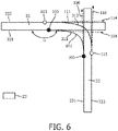
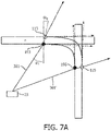
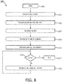
- FIGS. 5-7 schematically depict several steps and FIG. 8 depicts a flowchart of a computer-implemented method 200 of designing such a light-transmissive cover 30 in accordance with embodiments of the present invention.
- the method 200 starts in 201, e.g. by a designer launching a computer program on a computer that implements the computer-implemented method 200, after which the method 200 proceeds to 203 in which the designer specifies the mounting position of the SSL elements 23 within the optical chamber 15 of the luminaire housing 10.
- the designer may provide this specification in any suitable manner, e.g. using any suitable user interface of the computer hosting the computer-implemented method 200.
- the light-transmissive cover 30 is to be realized in a specified material having a defined refractive index.
- the refractive index of the material may be defined as the refractive index of that material at a wavelength of 550 nm.
- any refractive index of that material within the visible spectrum e.g. from 400 nm to 700 nm, may be used. It may be assumed that variations in the refractive index of the material within the visible spectrum are small enough such that they may be ignored.
- FIG. 5 The positioning of the specified SSL element 23 and further sections 33 of the light-transmissive cover 30 is schematically depicted in FIG. 5 , in which the further sections 33 (here planar sections) are represented by (overlapping) rectangles having a thickness or width corresponding to the specified thickness of the further sections 33 by way of non-limiting example.
- the method 200 generates a first spline 101 representing the inner surface 311 of the curved corner section 31 of the light-transmissive cover 30 as shown in FIG. 6 , which first spline 101 is delimited by opposing endpoints 103 and 105 defining the boundary between the curved corner section 31 and the adjacent further sections 33.
- the first endpoint 103 is associated with a first vector 104 and the second endpoint 105 is associated with a second vector 106, which vectors have a length and direction corresponding to the curvature of the first spline 101.
- An angle ⁇ between each vector and the inner surface 331 of the adjacent planar section 33 should not exceed 180°, i.e.
- the designer may adjust the positions of the first endpoint 103 and the second endpoint 105 in 209 as well as the length of the vectors 104 and 106 in order to achieve the desired curvature of the inner surface 311 of the curved corner section 31 of the light-transmissive cover 30.
- the first spline 101 may be shaped to have any shape within the aforementioned design requirements.
- the method 200 calculates a second spline 111 representing the outer surface 313 of the curved corner section 31 of the light-transmissive cover 30 in 211.
- the second spline 111 has a first outer endpoint 113 associated with a first further vector 114 and a second outer endpoint 115 associated with a second further vector 116, which further vectors have a respective length defining the curvature of the second spline 111.
- the first outer endpoint 113 and the second outer endpoint 115 define the boundary between the second spline 111 and the outer surface 333 of the adjacent further section 33.
- An angle ⁇ (not shown) between each further vector 114, 116 and the outer surface 333 of the adjacent further section 33 should not exceed 180°, i.e. the second spline 111 preferably is arranged tangentially to these outer surfaces 333.
- ⁇ i is the angle of incidence of a light ray 301, 301' with an inner endpoint 103, 105 of the first spline 101 of the light-transmissive cover 30 (with respect to a defined surface normal)
- ⁇ e is the angle of the light ray 301, 301' (with respect to a defined surface normal) within the housing material
- n is the given refraction index of the material of the housing.
- the respective positions where the light rays 301, 301' intersect the exit surface define the positions of the outer endpoints 113 and 115 of the second spline 111.
- a simulated ray fan of a resulting light-transmissive cover 30 is schematically depicted in FIG. 9 , from which the disappearance of the boundary artefacts highlighted in FIG. 4 is clearly noticeable, thereby demonstrating that the imposed boundary conditions by positioning both an inner endpoint and a proximal outer endpoint of the respective splines 101 and 111 on the same ray path significantly improves the optical performance of the luminaire housing 10 including the light-transmissive cover 30.
- PMMA PolyMethylMethAcrylate
- Said light chamber comprising a mounting region 24 for mounting at least one solid state lighting element, wherein the rounded corner section has an inner surface 311 having opposing inner endpoints 103, 105 and an outer surface 313 having opposing outer endpoints 113, 115.
- a tangent to the surface 311,313 of the rounded corner section 31 is parallel to a tangent to a proximal further inner surface 331,333 of its proximal further section 33, i.e. both the inner and outer surface have a smooth transision between the further, linear, planar section and the rounded corner section, in other words said transition is without a discontinuity such as a kink or step.
- the mounting region 24 is outside an area range between the wall 29 and at least one of said planes P1,P2 alongside its proximal further section of said wall for no ray of light 301, 301' emitted by the at least one solid state lighting element entering the light-transmissive cover via the further inner surface 331 of the further section to exits the light-transmissive cover from the outer surface of the rounded corner section.
- a ray 301, 301'entering the cover via an inner wall of a further, linear planar section, at an angle ⁇ i, exits the cover via a further, linear, planar section of the outer wall at an angle ⁇ o, wherein ⁇ i ⁇ o.
- the method 200 may check in 213 if after positioning of the outer endpoints 113, 115 of the second spline 111 as explained above the light-transmissive cover 30 has the desired optical performance.
- this for example may be achieved by optical simulation.
- optical simulation tools are well-known per se and are therefore not explained in further detail for the sake of brevity only.
- the method 200 may proceed to 215 in which the curvature of the second spline 111 may be adjusted without repositioning of its outer endpoints 113, 115, such that the boundary conditions achieved by the positioning of these outer endpoints is not affected by the adjustment of this curvature.
- the curvature of the second spline 111 may be adjusted by the designer by altering the length of at least one of the first further vector 114 and the second further vector 116.
- the designer may adjust the curvature of the first spline 101, for example by adjusting the length of at least one of the first vector 104 and the second vector 106.
- the designer may reposition at least one of the outer endpoints 113, 115 away from its adjacent further section 33, such that a light ray incident on a curved inner surface 311 of the light-transmissive cover 30 may exit the cover through the outer surface 333 of a further section 33 but no light ray incident on a planar inner surface section 331 of the light-transmissive cover 30 can exit the cover through the outer surface 313 of a curved corner section 33.
- This may further improve the optical boundary effects by blending the transition between the curved corner section 31 and an adjacent planar section 33.
- the method 200 may revert back to 213 in which it is checked if the adjusted design of the curved corner section 31 of the light-transmissive cover 30 is represented by the first spline 101 and the second spline 111 has improved optical characteristics, e.g. improved convergence or divergence of light rays originating from the SSL element 23 passing through the curved corner section 31. If this is not the case, the adjustment may be rejected by the method 200 or alternatively the method 200 may provide an indication of the change in optical characteristics, e.g. a visible indication on a display device coupled to the computer on which the method 200 is executed.
- the adjusted design of the curved corner section 31 may be checked in 213 if the adjusted design still complies with design requirements, e.g. manufacturing tolerances of the light-transmissive cover 30.
- design requirements e.g. manufacturing tolerances of the light-transmissive cover 30.
- the ability to individually adjust the curvature of the inner surface 311 and the outer surface 313 of such a curved corner section 31 may lead to a curved corner section 31 of non-constant thickness, which thickness variation may exceed design tolerances or alternatively may lead to a minimum or maximum thickness of the curved corner section 31 exceeding design tolerances.
- the method 200 may reject the design alteration as previously explained after which the method 200 may return to 215. This iterative process may be repeated until it is decided in 213 that the curved corner section 31 has the desired optical performance and complies with design requirements, after which the method 200 may terminate in 217, for example with the generation of an output comprising a design specification of the thus designed light-transmissive cover 30, e.g. a CAD file or the like.
- Such a design specification may be used to manufacture a mold or the like in which the light transmissive cover 30 may be formed, e.g. by extrusion or another suitable manufacturing method, e.g. (injection-)moulding.
- the light transmissive cover 30 may be manufactured using such a mold or the like, thereby providing at least part of a luminaire housing 10 having improved optical performance when used in conjunction with correctly positioned SSL elements 23, i.e. in a designated mounting region within the optical chamber 15, as previously explained.
- each spline 101, 111 may be defined by intermediate points in addition to opposing endpoints, e.g. to provide a higher order spline in which the curvature of the corresponding surface of the curved corner section 31 may be controlled in a more fine-grained manner.
- the inner and outer surfaces of the curved corner section 31 do not necessarily need to be represented by splines but may be represented by any suitable adjustable curved element.
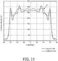
- FIG. 10 schematically depicts an aspect including a curved corner section of a prior art light-transmissive cover 30' designed in accordance with the above described prior art design method leading to identically curved inner and outer surfaces of a curved corner section 31 and a light-transmissive cover 30 designed in accordance with an embodiment of the present invention.
- the optical performance of these covers is schematically depicted in FIG. 11 , which depicts the intensity distribution of the prior art cover 30' and the cover 30 designed in accordance with an embodiment of the present invention as a function of an emission angle from a SSL element 23 placed within an optical chamber at least partially delimited by the prior art cover 30' and inventive cover 30 respectively.
- the intensity distribution of the inventive cover 30 is further highlighted by the arrow in FIG. 11 .
Landscapes
- Engineering & Computer Science (AREA)
- General Engineering & Computer Science (AREA)
- Physics & Mathematics (AREA)
- Microelectronics & Electronic Packaging (AREA)
- Optics & Photonics (AREA)
- Non-Portable Lighting Devices Or Systems Thereof (AREA)
- Fastening Of Light Sources Or Lamp Holders (AREA)
Claims (12)
- Leuchtengehäuse (10), das durch eine Abdeckung (30) oder durch eine Abdeckung in Zusammenwirkung mit einer Basis (20) gebildet ist, wobei das Leuchtengehäuse eine Lichtkammer (15) umfasst, die mindestens teilweise durch eine lichtdurchlässige Wand (29) mit einer Dicke Tw der Abdeckung (30) begrenzt ist, die mindestens einen abgerundeten Eckabschnitt (31) zwischen zwei weiteren geradlinigen, ebenen Abschnitten (33) umfasst, wobei die Lichtkammer einen Montagebereich (24) umfasst, in dem mindestens ein Festkörperbeleuchtungselement montiert ist, wobei der abgerundete Eckabschnitt eine Innenfläche (311) mit gegenüberliegenden inneren Endpunkten (103, 105) und eine Außenfläche (313) mit gegenüberliegenden äußeren Endpunkten (113, 115) aufweist, wobei die lichtdurchlässige Abdeckung (30) ein Paar der abgerundeten Eckabschnitte (31) umfasst, und wobei einer der weiteren Abschnitte (33) zwischen dem Paar der abgerundeten Eckabschnitte (31) angeordnet ist, und wobei die lichtdurchlässige Wand eine konstante Dicke aufweist, dadurch gekennzeichnet, dass- eine Ebene (P1, P2) unter dem kritischen Winkel θc an der Innenfläche (311) an einem inneren Endpunkt (103, 105) sich nicht durch die Außenfläche (313) des abgerundeten Eckabschnitts (31) erstreckt, sodass kein Lichtstrahl (301, 301'), der von dem mindestens einen Festkörperbeleuchtungselement emittiert wird, der in die lichtdurchlässige Abdeckung über die weitere Innenfläche (331) des weiteren Abschnitts eintritt, aus der lichtdurchlässigen Abdeckung an der Außenfläche des abgerundeten Eckabschnitts austritt.
- Leuchtengehäuse (10) nach Anspruch 1, wobei der Montagebereich (24) außerhalb eines Flächenbereichs zwischen der Wand (29) und mindestens einer der Ebenen (P1, P2) entlang ihres proximalen weiteren Abschnitts der Wand liegt.
- Leuchtengehäuse (10) nach Anspruch 1 oder 2, wobei jeder innere Endpunkt (103, 105) relativ zu dem äußeren Endpunkt (113, 115) proximal zu dem inneren Endpunkt positioniert ist, sodass sich ein Lichtstrahl (301, 301'), der von dem mindestens einen Festkörper-Leuchtelement (23) emittiert wird und unter einem Winkel θi in die lichtdurchlässige Abdeckung (30) durch einen solchen inneren Endpunkt eintritt, tangential zu dem äußeren Endpunkt in der Nähe des inneren Endpunkts ausbreitet.
- Leuchtengehäuse (10) nach Anspruch 1, 2 oder 3, wobei an den Endpunkten (103, 105, 112, 115) eine Tangente an die Oberfläche (311, 313) des abgerundeten Eckabschnitts (31) parallel zu einer Tangente an eine proximale weitere Innenfläche (331, 333) seines proximalen weiteren Abschnitts (33) ist.
- Leuchtengehäuse (10) nach einem der Ansprüche 1 bis 4, wobei der Montagebereich und der abgerundete Eckabschnitt (31) in parallelen Längsrichtungen langgestreckt sind.
- Computerimplementiertes Verfahren (200) zum Entwerfen einer lichtdurchlässigen Abdeckung (30) mit einem definierten Brechungsindex und umfassend mindestens einen abgerundeten Eckabschnitt (31) zwischen zwei weiteren Abschnitten (33) für ein Leuchtengehäuse, das ferner eine Lichtkammer (15) umfasst, die durch die lichtdurchlässige Abdeckung begrenzt ist, und wobei die lichtdurchlässige Abdeckung (30) ein Paar der abgerundeten Eckabschnitte (31) umfasst, wobei einer der weiteren Abschnitte (33) zwischen dem Paar der abgerundeten Eckabschnitte (31) angeordnet ist, das Verfahren umfassend:Empfangen (203) einer definierten Position einer Festkörperlichtquelle innerhalb der Lichtkammer;Empfangen (205) einer Spezifikation der Ausrichtung, Dicke und Position jedes der weiteren Abschnitte relativ zu der definierten Position;Definieren (207) eines ersten Splines (101), der eine Innenfläche des abgerundeten Eckabschnitts darstellt, wobei der erste Spline einen ersten inneren Endpunkt (103), der mit einer Innenfläche (331) des ersten weiteren Abschnitts der beiden weiteren Abschnitte verbunden ist, und einen zweiten inneren Endpunkt (105), der mit einer Innenfläche des zweiten weiteren Abschnitts der beiden weiteren Abschnitte verbunden ist, umfasst;Definieren (207) eines zweiten Splines (111), der eine Außenfläche des abgerundeten Eckprofils darstellt, wobei der zweite Spline einen ersten äußeren Endpunkt (113), der mit einer äußeren Oberfläche (333) des ersten weiteren Abschnitts verbunden ist, und einen zweiten äußeren Endpunkt (115), der mit einer äußeren Oberfläche des zweiten weiteren Abschnitts verbunden ist, umfasst, indem die Position des ersten inneren Endpunkts und des zweiten äußeren Endpunkts so berechnet wird, dass ein simulierter erster Strahl (301) der Festkörperlichtquelle, der durch den ersten inneren Endpunkt verläuft, auch durch den ersten äußeren Endpunkt verläuft, und ein simulierter zweiter Strahl (301') der Festkörperlichtquelle, der durch den zweiten inneren Endpunkt verläuft, auch durch den zweiten äußeren Endpunkt verläuft; undErzeugen (217) einer Ausgabe einer Designspezifikation der lichtdurchlässigen Abdeckung einschließlich der definierten ersten und zweiten Splines, der Wanddicke Tw und der relativen Positionen des inneren Endpunkts und des proximalen äußeren Endpunkts.
- Computerimplementiertes Verfahren (200) nach Anspruch 6, ferner umfassend:Berechnen eines Strahlengangs (301, 301') durch die lichtdurchlässige Abdeckung (30) für jeden Strahl basierend auf einem Einfallswinkel des Strahls mit dem inneren Endpunkt (103, 105) und dem definierten Brechungsindex; undPositionieren des entsprechenden äußeren Endpunkts (113, 115) auf dem Strahlengang.
- Computerimplementiertes Verfahren nach Anspruch 6 oder 7, ferner umfassend:Empfangen (215) einer Anpassung einer Krümmung des zweiten Splines (111);Berechnen eines Konvergenz- oder Divergenzgrades für Lichtstrahlen, die von der Festkörperlichtquelle (23) ausgehen und aus der Außenfläche (313) des abgerundeten Eckabschnitts (31) für die angepasste Krümmung austreten; undAkzeptieren der Krümmungsanpassung, wenn der Konvergenz- oder Divergenzgrad eine Verbesserung im Vergleich zu Lichtstrahlen aufweist, die von der Festkörperlichtquelle ausgehen und aus der Außenfläche des abgerundeten Eckabschnitts austreten, wie er durch den zweiten Spline (111) ohne die angepasste Krümmung definiert ist.
- Computerimplementiertes Verfahren (200) nach Anspruch 8, ferner umfassend:Bestimmen (213) einer Dicke über den abgerundeten Eckabschnitt (31) einschließlich der Anpassung an die Krümmung des zweiten Splines (111); undAblehnen der Krümmungsanpassung, wenn die Dicke eine Designtoleranz überschreitet.
- Computerimplementiertes Verfahren (200) nach Anspruch 8 oder 9, wobei:die Krümmung des ersten Splines (101) durch einen ersten Vektor (104), der dem ersten inneren Endpunkt (103) zugeordnet ist, und einen zweiten Vektor, der dem zweiten inneren Endpunkt zugeordnet ist, definiert ist;die Krümmung des zweiten Splines durch einen ersten weiteren Vektor, der dem ersten äußeren Endpunkt zugeordnet ist, und einen zweiten weiteren Vektor, der dem zweiten äußeren Endpunkt zugeordnet ist, definiert ist; unddas Empfangen einer Anpassung einer Krümmung des zweiten Splines das Empfangen einer Längenänderung von mindestens einem des ersten weiteren Vektors und des zweiten weiteren Vektors umfasst.
- Computerimplementiertes Verfahren nach einem der Ansprüche 6 bis 10, wobei jeder Spline tangential zu dem weiteren Abschnitt verläuft, mit dem er verbunden ist.
- Verfahren zum Herstellen einer lichtdurchlässigen Abdeckung (30) für ein Leuchtengehäuse (10), wobei die Abdeckung einen definierten Brechungsindex aufweist und mindestens einen abgerundeten Eckabschnitt (31) zwischen zwei weiteren Abschnitten (33) umfasst, wobei die Abdeckung (30) ferner ein Paar der abgerundeten Eckabschnitte (31) umfasst, wobei einer der weiteren Abschnitte (33) zwischen dem Paar der abgerundeten Eckabschnitte (31) angeordnet ist, das Verfahren umfassend:Herstellen einer Form für die lichtdurchlässige Abdeckung unter Verwendung der Designspezifikation einschließlich Erzeugen (217) einer Ausgabe einer Designspezifikation der lichtdurchlässigen Abdeckung einschließlich der Wanddicke Tw und der relativen Positionen der inneren Endpunkte und der proximalen äußeren Endpunkte und der definierten ersten und zweiten Splines, wie sie durch das computerimplementierte Verfahren (200) nach einem der Ansprüche 6 bis 11 erzeugt wurden; undHerstellen der lichtdurchlässigen Abdeckung mit der Form.
Applications Claiming Priority (2)
| Application Number | Priority Date | Filing Date | Title |
|---|---|---|---|
| EP16200018 | 2016-11-22 | ||
| PCT/EP2017/079471 WO2018095805A1 (en) | 2016-11-22 | 2017-11-16 | Cover for led luminaires |
Publications (2)
| Publication Number | Publication Date |
|---|---|
| EP3545231A1 EP3545231A1 (de) | 2019-10-02 |
| EP3545231B1 true EP3545231B1 (de) | 2022-05-18 |
Family
ID=57391833
Family Applications (1)
| Application Number | Title | Priority Date | Filing Date |
|---|---|---|---|
| EP17800522.9A Active EP3545231B1 (de) | 2016-11-22 | 2017-11-16 | Abdeckung für led-leuchten |
Country Status (5)
| Country | Link |
|---|---|
| US (1) | US10948156B2 (de) |
| EP (1) | EP3545231B1 (de) |
| CN (1) | CN109952468B (de) |
| ES (1) | ES2922648T3 (de) |
| WO (1) | WO2018095805A1 (de) |
Families Citing this family (2)
| Publication number | Priority date | Publication date | Assignee | Title |
|---|---|---|---|---|
| US12372219B2 (en) * | 2014-05-30 | 2025-07-29 | Cree Lighting Usa Llc | LED luminaire with a cavity, finned interior, and a curved outer wall extending from a surface on which the light source is mounted |
| WO2021209492A1 (en) * | 2020-04-15 | 2021-10-21 | CommScope Connectivity Belgium BV | Device and method for sealing cables in telecommunications enclosures |
Citations (2)
| Publication number | Priority date | Publication date | Assignee | Title |
|---|---|---|---|---|
| CN101684930B (zh) * | 2008-09-22 | 2011-07-20 | 义守大学 | 发光二极管灯管装置 |
| US20160195247A1 (en) * | 2013-07-23 | 2016-07-07 | Zumtobel Lighting Gmbh | Led illumination module |
Family Cites Families (20)
| Publication number | Priority date | Publication date | Assignee | Title |
|---|---|---|---|---|
| JPS59204815A (ja) | 1983-05-09 | 1984-11-20 | Yamagata Daigaku | 照明用照度平均化レンズ |
| FR2829223B1 (fr) * | 2001-08-31 | 2004-11-26 | Valeo Vision | Dispositif d'eclairage ou de signalisation pour vehicule automobile |
| DE202008014905U1 (de) | 2008-04-01 | 2009-08-13 | Zumtobel Lighting Gmbh | Lichtbandsystem |
| US20100073927A1 (en) * | 2008-09-21 | 2010-03-25 | Ian Lewin | Lens for Solid-State Light-Emitting Device |
| US9151460B2 (en) | 2009-07-21 | 2015-10-06 | 3M Innovative Properties Company | Light assembly |
| JP2011028946A (ja) | 2009-07-23 | 2011-02-10 | Atex Co Ltd | Led照明装置 |
| US8434914B2 (en) | 2009-12-11 | 2013-05-07 | Osram Sylvania Inc. | Lens generating a batwing-shaped beam distribution, and method therefor |
| CN201661991U (zh) | 2010-01-29 | 2010-12-01 | 宁波海富电器制造有限公司 | 一种节能路灯 |
| WO2012011528A1 (ja) | 2010-07-22 | 2012-01-26 | 京セラ株式会社 | 発光装置および照明装置 |
| CN201944775U (zh) | 2010-12-03 | 2011-08-24 | 张治洋 | Led灯的异形灯罩 |
| JP5660523B2 (ja) | 2010-12-13 | 2015-01-28 | コニカミノルタ株式会社 | 照射部材及び照明装置 |
| JP5825489B2 (ja) | 2012-07-30 | 2015-12-02 | 東芝ライテック株式会社 | ランプ、ランプ装置および照明器具 |
| CN104214660A (zh) | 2013-05-30 | 2014-12-17 | 海洋王(东莞)照明科技有限公司 | 灯具及灯罩 |
| US9222659B2 (en) * | 2013-06-28 | 2015-12-29 | Cree, Inc. | LED lamp |
| CN203421614U (zh) | 2013-07-24 | 2014-02-05 | 东莞市中实创半导体照明有限公司 | 一种led灯罩 |
| US9695991B2 (en) | 2013-08-30 | 2017-07-04 | Itc Incorporated | Diffused flexible LED linear light assembly |
| WO2015129671A1 (ja) | 2014-02-28 | 2015-09-03 | 三菱電機株式会社 | 照明器具、光源カバー、光制御部材、および光源ユニット |
| US10935211B2 (en) | 2014-05-30 | 2021-03-02 | Ideal Industries Lighting Llc | LED luminaire with a smooth outer dome and a cavity with a ridged inner surface |
| JP6331193B2 (ja) | 2014-06-23 | 2018-05-30 | パナソニックIpマネジメント株式会社 | Ledユニットおよびそれを用いた照明器具 |
| US20160258609A1 (en) | 2015-03-02 | 2016-09-08 | Rohm Co., Ltd. | Led lighting apparatus |
-
2017
- 2017-11-16 EP EP17800522.9A patent/EP3545231B1/de active Active
- 2017-11-16 WO PCT/EP2017/079471 patent/WO2018095805A1/en not_active Ceased
- 2017-11-16 CN CN201780071915.3A patent/CN109952468B/zh active Active
- 2017-11-16 ES ES17800522T patent/ES2922648T3/es active Active
- 2017-11-16 US US16/461,314 patent/US10948156B2/en active Active
Patent Citations (3)
| Publication number | Priority date | Publication date | Assignee | Title |
|---|---|---|---|---|
| CN101684930B (zh) * | 2008-09-22 | 2011-07-20 | 义守大学 | 发光二极管灯管装置 |
| US20160195247A1 (en) * | 2013-07-23 | 2016-07-07 | Zumtobel Lighting Gmbh | Led illumination module |
| EP3030833B1 (de) * | 2013-07-23 | 2017-05-31 | Zumtobel Lighting GmbH | Led-beleuchtungsmodul |
Also Published As
| Publication number | Publication date |
|---|---|
| US20200072437A1 (en) | 2020-03-05 |
| CN109952468B (zh) | 2021-10-12 |
| CN109952468A (zh) | 2019-06-28 |
| US10948156B2 (en) | 2021-03-16 |
| WO2018095805A1 (en) | 2018-05-31 |
| EP3545231A1 (de) | 2019-10-02 |
| ES2922648T3 (es) | 2022-09-19 |
Similar Documents
| Publication | Publication Date | Title |
|---|---|---|
| US10422943B2 (en) | Luminaire with light guide | |
| US20180149336A1 (en) | Lens array, vehicle-lamp lens group using lens array, and vehicle-lamp assembly using vehicle-lamp lens group | |
| US20090128921A1 (en) | Led collimator having spline surfaces and related methods | |
| US12136689B2 (en) | Hybrid lens for controlled light distribution | |
| EP3538932B1 (de) | Led-strahlformung | |
| JP6678524B2 (ja) | 照明装置 | |
| EP3545231B1 (de) | Abdeckung für led-leuchten | |
| US20200319379A1 (en) | Optical output device and design method | |
| JP6143976B1 (ja) | 照明器具、特に道路照明用の照明器具 | |
| CN111033349A (zh) | 用于减少眩光同时维持led光源的混色和光束控制的全内反射透镜 | |
| US20140301086A1 (en) | Optical sheet and lighting device including the same | |
| KR20110054680A (ko) | Led 조명용 확산 부재 및 이를 구비한 led 조명등 | |
| US9915411B2 (en) | Open light flow optics | |
| CN107667248B (zh) | 管状发光设备 | |
| JP6810701B2 (ja) | ライトガイドを使用する照明システム | |
| KR101629464B1 (ko) | 램프캡을 포함하는 led램프 | |
| HK40026517B (en) | Total internal reflection lens for lessening glare while maintaining color mixing and beam control of an led light source | |
| HK40026517A (en) | Total internal reflection lens for lessening glare while maintaining color mixing and beam control of an led light source |
Legal Events
| Date | Code | Title | Description |
|---|---|---|---|
| STAA | Information on the status of an ep patent application or granted ep patent |
Free format text: STATUS: UNKNOWN |
|
| STAA | Information on the status of an ep patent application or granted ep patent |
Free format text: STATUS: THE INTERNATIONAL PUBLICATION HAS BEEN MADE |
|
| PUAI | Public reference made under article 153(3) epc to a published international application that has entered the european phase |
Free format text: ORIGINAL CODE: 0009012 |
|
| STAA | Information on the status of an ep patent application or granted ep patent |
Free format text: STATUS: REQUEST FOR EXAMINATION WAS MADE |
|
| 17P | Request for examination filed |
Effective date: 20190624 |
|
| AK | Designated contracting states |
Kind code of ref document: A1 Designated state(s): AL AT BE BG CH CY CZ DE DK EE ES FI FR GB GR HR HU IE IS IT LI LT LU LV MC MK MT NL NO PL PT RO RS SE SI SK SM TR |
|
| AX | Request for extension of the european patent |
Extension state: BA ME |
|
| DAV | Request for validation of the european patent (deleted) | ||
| DAX | Request for extension of the european patent (deleted) | ||
| STAA | Information on the status of an ep patent application or granted ep patent |
Free format text: STATUS: EXAMINATION IS IN PROGRESS |
|
| 17Q | First examination report despatched |
Effective date: 20200616 |
|
| GRAP | Despatch of communication of intention to grant a patent |
Free format text: ORIGINAL CODE: EPIDOSNIGR1 |
|
| STAA | Information on the status of an ep patent application or granted ep patent |
Free format text: STATUS: GRANT OF PATENT IS INTENDED |
|
| INTG | Intention to grant announced |
Effective date: 20211208 |
|
| GRAS | Grant fee paid |
Free format text: ORIGINAL CODE: EPIDOSNIGR3 |
|
| GRAA | (expected) grant |
Free format text: ORIGINAL CODE: 0009210 |
|
| STAA | Information on the status of an ep patent application or granted ep patent |
Free format text: STATUS: THE PATENT HAS BEEN GRANTED |
|
| AK | Designated contracting states |
Kind code of ref document: B1 Designated state(s): AL AT BE BG CH CY CZ DE DK EE ES FI FR GB GR HR HU IE IS IT LI LT LU LV MC MK MT NL NO PL PT RO RS SE SI SK SM TR |
|
| REG | Reference to a national code |
Ref country code: GB Ref legal event code: FG4D |
|
| REG | Reference to a national code |
Ref country code: CH Ref legal event code: EP |
|
| REG | Reference to a national code |
Ref country code: IE Ref legal event code: FG4D |
|
| REG | Reference to a national code |
Ref country code: DE Ref legal event code: R096 Ref document number: 602017057675 Country of ref document: DE |
|
| REG | Reference to a national code |
Ref country code: AT Ref legal event code: REF Ref document number: 1493341 Country of ref document: AT Kind code of ref document: T Effective date: 20220615 |
|
| REG | Reference to a national code |
Ref country code: LT Ref legal event code: MG9D |
|
| REG | Reference to a national code |
Ref country code: ES Ref legal event code: FG2A Ref document number: 2922648 Country of ref document: ES Kind code of ref document: T3 Effective date: 20220919 |
|
| REG | Reference to a national code |
Ref country code: NL Ref legal event code: MP Effective date: 20220518 |
|
| REG | Reference to a national code |
Ref country code: AT Ref legal event code: MK05 Ref document number: 1493341 Country of ref document: AT Kind code of ref document: T Effective date: 20220518 |
|
| PG25 | Lapsed in a contracting state [announced via postgrant information from national office to epo] |
Ref country code: SE Free format text: LAPSE BECAUSE OF FAILURE TO SUBMIT A TRANSLATION OF THE DESCRIPTION OR TO PAY THE FEE WITHIN THE PRESCRIBED TIME-LIMIT Effective date: 20220518 Ref country code: PT Free format text: LAPSE BECAUSE OF FAILURE TO SUBMIT A TRANSLATION OF THE DESCRIPTION OR TO PAY THE FEE WITHIN THE PRESCRIBED TIME-LIMIT Effective date: 20220919 Ref country code: NO Free format text: LAPSE BECAUSE OF FAILURE TO SUBMIT A TRANSLATION OF THE DESCRIPTION OR TO PAY THE FEE WITHIN THE PRESCRIBED TIME-LIMIT Effective date: 20220818 Ref country code: NL Free format text: LAPSE BECAUSE OF FAILURE TO SUBMIT A TRANSLATION OF THE DESCRIPTION OR TO PAY THE FEE WITHIN THE PRESCRIBED TIME-LIMIT Effective date: 20220518 Ref country code: LT Free format text: LAPSE BECAUSE OF FAILURE TO SUBMIT A TRANSLATION OF THE DESCRIPTION OR TO PAY THE FEE WITHIN THE PRESCRIBED TIME-LIMIT Effective date: 20220518 Ref country code: HR Free format text: LAPSE BECAUSE OF FAILURE TO SUBMIT A TRANSLATION OF THE DESCRIPTION OR TO PAY THE FEE WITHIN THE PRESCRIBED TIME-LIMIT Effective date: 20220518 Ref country code: GR Free format text: LAPSE BECAUSE OF FAILURE TO SUBMIT A TRANSLATION OF THE DESCRIPTION OR TO PAY THE FEE WITHIN THE PRESCRIBED TIME-LIMIT Effective date: 20220819 Ref country code: FI Free format text: LAPSE BECAUSE OF FAILURE TO SUBMIT A TRANSLATION OF THE DESCRIPTION OR TO PAY THE FEE WITHIN THE PRESCRIBED TIME-LIMIT Effective date: 20220518 Ref country code: BG Free format text: LAPSE BECAUSE OF FAILURE TO SUBMIT A TRANSLATION OF THE DESCRIPTION OR TO PAY THE FEE WITHIN THE PRESCRIBED TIME-LIMIT Effective date: 20220818 Ref country code: AT Free format text: LAPSE BECAUSE OF FAILURE TO SUBMIT A TRANSLATION OF THE DESCRIPTION OR TO PAY THE FEE WITHIN THE PRESCRIBED TIME-LIMIT Effective date: 20220518 |
|
| PG25 | Lapsed in a contracting state [announced via postgrant information from national office to epo] |
Ref country code: RS Free format text: LAPSE BECAUSE OF FAILURE TO SUBMIT A TRANSLATION OF THE DESCRIPTION OR TO PAY THE FEE WITHIN THE PRESCRIBED TIME-LIMIT Effective date: 20220518 Ref country code: PL Free format text: LAPSE BECAUSE OF FAILURE TO SUBMIT A TRANSLATION OF THE DESCRIPTION OR TO PAY THE FEE WITHIN THE PRESCRIBED TIME-LIMIT Effective date: 20220518 Ref country code: LV Free format text: LAPSE BECAUSE OF FAILURE TO SUBMIT A TRANSLATION OF THE DESCRIPTION OR TO PAY THE FEE WITHIN THE PRESCRIBED TIME-LIMIT Effective date: 20220518 Ref country code: IS Free format text: LAPSE BECAUSE OF FAILURE TO SUBMIT A TRANSLATION OF THE DESCRIPTION OR TO PAY THE FEE WITHIN THE PRESCRIBED TIME-LIMIT Effective date: 20220918 |
|
| PG25 | Lapsed in a contracting state [announced via postgrant information from national office to epo] |
Ref country code: SM Free format text: LAPSE BECAUSE OF FAILURE TO SUBMIT A TRANSLATION OF THE DESCRIPTION OR TO PAY THE FEE WITHIN THE PRESCRIBED TIME-LIMIT Effective date: 20220518 Ref country code: SK Free format text: LAPSE BECAUSE OF FAILURE TO SUBMIT A TRANSLATION OF THE DESCRIPTION OR TO PAY THE FEE WITHIN THE PRESCRIBED TIME-LIMIT Effective date: 20220518 Ref country code: RO Free format text: LAPSE BECAUSE OF FAILURE TO SUBMIT A TRANSLATION OF THE DESCRIPTION OR TO PAY THE FEE WITHIN THE PRESCRIBED TIME-LIMIT Effective date: 20220518 Ref country code: EE Free format text: LAPSE BECAUSE OF FAILURE TO SUBMIT A TRANSLATION OF THE DESCRIPTION OR TO PAY THE FEE WITHIN THE PRESCRIBED TIME-LIMIT Effective date: 20220518 Ref country code: DK Free format text: LAPSE BECAUSE OF FAILURE TO SUBMIT A TRANSLATION OF THE DESCRIPTION OR TO PAY THE FEE WITHIN THE PRESCRIBED TIME-LIMIT Effective date: 20220518 Ref country code: CZ Free format text: LAPSE BECAUSE OF FAILURE TO SUBMIT A TRANSLATION OF THE DESCRIPTION OR TO PAY THE FEE WITHIN THE PRESCRIBED TIME-LIMIT Effective date: 20220518 |
|
| REG | Reference to a national code |
Ref country code: DE Ref legal event code: R097 Ref document number: 602017057675 Country of ref document: DE |
|
| PLBE | No opposition filed within time limit |
Free format text: ORIGINAL CODE: 0009261 |
|
| STAA | Information on the status of an ep patent application or granted ep patent |
Free format text: STATUS: NO OPPOSITION FILED WITHIN TIME LIMIT |
|
| PG25 | Lapsed in a contracting state [announced via postgrant information from national office to epo] |
Ref country code: AL Free format text: LAPSE BECAUSE OF FAILURE TO SUBMIT A TRANSLATION OF THE DESCRIPTION OR TO PAY THE FEE WITHIN THE PRESCRIBED TIME-LIMIT Effective date: 20220518 |
|
| 26N | No opposition filed |
Effective date: 20230221 |
|
| PG25 | Lapsed in a contracting state [announced via postgrant information from national office to epo] |
Ref country code: SI Free format text: LAPSE BECAUSE OF FAILURE TO SUBMIT A TRANSLATION OF THE DESCRIPTION OR TO PAY THE FEE WITHIN THE PRESCRIBED TIME-LIMIT Effective date: 20220518 |
|
| P01 | Opt-out of the competence of the unified patent court (upc) registered |
Effective date: 20230425 |
|
| PG25 | Lapsed in a contracting state [announced via postgrant information from national office to epo] |
Ref country code: MC Free format text: LAPSE BECAUSE OF FAILURE TO SUBMIT A TRANSLATION OF THE DESCRIPTION OR TO PAY THE FEE WITHIN THE PRESCRIBED TIME-LIMIT Effective date: 20220518 |
|
| REG | Reference to a national code |
Ref country code: CH Ref legal event code: PL |
|
| REG | Reference to a national code |
Ref country code: BE Ref legal event code: MM Effective date: 20221130 |
|
| PG25 | Lapsed in a contracting state [announced via postgrant information from national office to epo] |
Ref country code: LI Free format text: LAPSE BECAUSE OF NON-PAYMENT OF DUE FEES Effective date: 20221130 Ref country code: CH Free format text: LAPSE BECAUSE OF NON-PAYMENT OF DUE FEES Effective date: 20221130 |
|
| PG25 | Lapsed in a contracting state [announced via postgrant information from national office to epo] |
Ref country code: LU Free format text: LAPSE BECAUSE OF NON-PAYMENT OF DUE FEES Effective date: 20221116 |
|
| PG25 | Lapsed in a contracting state [announced via postgrant information from national office to epo] |
Ref country code: IE Free format text: LAPSE BECAUSE OF NON-PAYMENT OF DUE FEES Effective date: 20221116 |
|
| PG25 | Lapsed in a contracting state [announced via postgrant information from national office to epo] |
Ref country code: BE Free format text: LAPSE BECAUSE OF NON-PAYMENT OF DUE FEES Effective date: 20221130 |
|
| PG25 | Lapsed in a contracting state [announced via postgrant information from national office to epo] |
Ref country code: HU Free format text: LAPSE BECAUSE OF FAILURE TO SUBMIT A TRANSLATION OF THE DESCRIPTION OR TO PAY THE FEE WITHIN THE PRESCRIBED TIME-LIMIT; INVALID AB INITIO Effective date: 20171116 |
|
| PG25 | Lapsed in a contracting state [announced via postgrant information from national office to epo] |
Ref country code: CY Free format text: LAPSE BECAUSE OF FAILURE TO SUBMIT A TRANSLATION OF THE DESCRIPTION OR TO PAY THE FEE WITHIN THE PRESCRIBED TIME-LIMIT Effective date: 20220511 |
|
| PG25 | Lapsed in a contracting state [announced via postgrant information from national office to epo] |
Ref country code: MK Free format text: LAPSE BECAUSE OF FAILURE TO SUBMIT A TRANSLATION OF THE DESCRIPTION OR TO PAY THE FEE WITHIN THE PRESCRIBED TIME-LIMIT Effective date: 20220511 |
|
| PG25 | Lapsed in a contracting state [announced via postgrant information from national office to epo] |
Ref country code: MT Free format text: LAPSE BECAUSE OF FAILURE TO SUBMIT A TRANSLATION OF THE DESCRIPTION OR TO PAY THE FEE WITHIN THE PRESCRIBED TIME-LIMIT Effective date: 20220511 |
|
| PG25 | Lapsed in a contracting state [announced via postgrant information from national office to epo] |
Ref country code: BG Free format text: LAPSE BECAUSE OF FAILURE TO SUBMIT A TRANSLATION OF THE DESCRIPTION OR TO PAY THE FEE WITHIN THE PRESCRIBED TIME-LIMIT Effective date: 20220518 |
|
| PG25 | Lapsed in a contracting state [announced via postgrant information from national office to epo] |
Ref country code: BG Free format text: LAPSE BECAUSE OF FAILURE TO SUBMIT A TRANSLATION OF THE DESCRIPTION OR TO PAY THE FEE WITHIN THE PRESCRIBED TIME-LIMIT Effective date: 20220518 |
|
| PGFP | Annual fee paid to national office [announced via postgrant information from national office to epo] |
Ref country code: DE Payment date: 20250129 Year of fee payment: 8 |
|
| PG25 | Lapsed in a contracting state [announced via postgrant information from national office to epo] |
Ref country code: TR Free format text: LAPSE BECAUSE OF FAILURE TO SUBMIT A TRANSLATION OF THE DESCRIPTION OR TO PAY THE FEE WITHIN THE PRESCRIBED TIME-LIMIT Effective date: 20220518 |
|
| PGFP | Annual fee paid to national office [announced via postgrant information from national office to epo] |
Ref country code: GB Payment date: 20251125 Year of fee payment: 9 |
|
| PGFP | Annual fee paid to national office [announced via postgrant information from national office to epo] |
Ref country code: IT Payment date: 20251121 Year of fee payment: 9 |
|
| PGFP | Annual fee paid to national office [announced via postgrant information from national office to epo] |
Ref country code: FR Payment date: 20251124 Year of fee payment: 9 |
|
| PGFP | Annual fee paid to national office [announced via postgrant information from national office to epo] |
Ref country code: ES Payment date: 20251209 Year of fee payment: 9 |