EP3544809B1 - Verfahren zur herstellung einer gebogenen verbundglasscheibe mit einer dünnen glasscheibe - Google Patents
Verfahren zur herstellung einer gebogenen verbundglasscheibe mit einer dünnen glasscheibe Download PDFInfo
- Publication number
- EP3544809B1 EP3544809B1 EP17791087.4A EP17791087A EP3544809B1 EP 3544809 B1 EP3544809 B1 EP 3544809B1 EP 17791087 A EP17791087 A EP 17791087A EP 3544809 B1 EP3544809 B1 EP 3544809B1
- Authority
- EP
- European Patent Office
- Prior art keywords
- glass pane
- glass
- pane
- support
- support pins
- Prior art date
- Legal status (The legal status is an assumption and is not a legal conclusion. Google has not performed a legal analysis and makes no representation as to the accuracy of the status listed.)
- Active
Links
Images


Classifications
-
- B—PERFORMING OPERATIONS; TRANSPORTING
- B32—LAYERED PRODUCTS
- B32B—LAYERED PRODUCTS, i.e. PRODUCTS BUILT-UP OF STRATA OF FLAT OR NON-FLAT, e.g. CELLULAR OR HONEYCOMB, FORM
- B32B17/00—Layered products essentially comprising sheet glass, or glass, slag, or like fibres
- B32B17/06—Layered products essentially comprising sheet glass, or glass, slag, or like fibres comprising glass as the main or only constituent of a layer, next to another layer of a specific material
- B32B17/10—Layered products essentially comprising sheet glass, or glass, slag, or like fibres comprising glass as the main or only constituent of a layer, next to another layer of a specific material of synthetic resin
- B32B17/10005—Layered products essentially comprising sheet glass, or glass, slag, or like fibres comprising glass as the main or only constituent of a layer, next to another layer of a specific material of synthetic resin laminated safety glass or glazing
- B32B17/10807—Making laminated safety glass or glazing; Apparatus therefor
- B32B17/10889—Making laminated safety glass or glazing; Apparatus therefor shaping the sheets, e.g. by using a mould
-
- B—PERFORMING OPERATIONS; TRANSPORTING
- B32—LAYERED PRODUCTS
- B32B—LAYERED PRODUCTS, i.e. PRODUCTS BUILT-UP OF STRATA OF FLAT OR NON-FLAT, e.g. CELLULAR OR HONEYCOMB, FORM
- B32B1/00—Layered products having a non-planar shape
-
- B—PERFORMING OPERATIONS; TRANSPORTING
- B32—LAYERED PRODUCTS
- B32B—LAYERED PRODUCTS, i.e. PRODUCTS BUILT-UP OF STRATA OF FLAT OR NON-FLAT, e.g. CELLULAR OR HONEYCOMB, FORM
- B32B17/00—Layered products essentially comprising sheet glass, or glass, slag, or like fibres
- B32B17/06—Layered products essentially comprising sheet glass, or glass, slag, or like fibres comprising glass as the main or only constituent of a layer, next to another layer of a specific material
- B32B17/10—Layered products essentially comprising sheet glass, or glass, slag, or like fibres comprising glass as the main or only constituent of a layer, next to another layer of a specific material of synthetic resin
- B32B17/10005—Layered products essentially comprising sheet glass, or glass, slag, or like fibres comprising glass as the main or only constituent of a layer, next to another layer of a specific material of synthetic resin laminated safety glass or glazing
- B32B17/10009—Layered products essentially comprising sheet glass, or glass, slag, or like fibres comprising glass as the main or only constituent of a layer, next to another layer of a specific material of synthetic resin laminated safety glass or glazing characterized by the number, the constitution or treatment of glass sheets
- B32B17/10036—Layered products essentially comprising sheet glass, or glass, slag, or like fibres comprising glass as the main or only constituent of a layer, next to another layer of a specific material of synthetic resin laminated safety glass or glazing characterized by the number, the constitution or treatment of glass sheets comprising two outer glass sheets
-
- B—PERFORMING OPERATIONS; TRANSPORTING
- B32—LAYERED PRODUCTS
- B32B—LAYERED PRODUCTS, i.e. PRODUCTS BUILT-UP OF STRATA OF FLAT OR NON-FLAT, e.g. CELLULAR OR HONEYCOMB, FORM
- B32B17/00—Layered products essentially comprising sheet glass, or glass, slag, or like fibres
- B32B17/06—Layered products essentially comprising sheet glass, or glass, slag, or like fibres comprising glass as the main or only constituent of a layer, next to another layer of a specific material
- B32B17/10—Layered products essentially comprising sheet glass, or glass, slag, or like fibres comprising glass as the main or only constituent of a layer, next to another layer of a specific material of synthetic resin
- B32B17/10005—Layered products essentially comprising sheet glass, or glass, slag, or like fibres comprising glass as the main or only constituent of a layer, next to another layer of a specific material of synthetic resin laminated safety glass or glazing
- B32B17/10009—Layered products essentially comprising sheet glass, or glass, slag, or like fibres comprising glass as the main or only constituent of a layer, next to another layer of a specific material of synthetic resin laminated safety glass or glazing characterized by the number, the constitution or treatment of glass sheets
- B32B17/10082—Properties of the bulk of a glass sheet
- B32B17/10119—Properties of the bulk of a glass sheet having a composition deviating from the basic composition of soda-lime glass, e.g. borosilicate
-
- B—PERFORMING OPERATIONS; TRANSPORTING
- B32—LAYERED PRODUCTS
- B32B—LAYERED PRODUCTS, i.e. PRODUCTS BUILT-UP OF STRATA OF FLAT OR NON-FLAT, e.g. CELLULAR OR HONEYCOMB, FORM
- B32B17/00—Layered products essentially comprising sheet glass, or glass, slag, or like fibres
- B32B17/06—Layered products essentially comprising sheet glass, or glass, slag, or like fibres comprising glass as the main or only constituent of a layer, next to another layer of a specific material
- B32B17/10—Layered products essentially comprising sheet glass, or glass, slag, or like fibres comprising glass as the main or only constituent of a layer, next to another layer of a specific material of synthetic resin
- B32B17/10005—Layered products essentially comprising sheet glass, or glass, slag, or like fibres comprising glass as the main or only constituent of a layer, next to another layer of a specific material of synthetic resin laminated safety glass or glazing
- B32B17/10009—Layered products essentially comprising sheet glass, or glass, slag, or like fibres comprising glass as the main or only constituent of a layer, next to another layer of a specific material of synthetic resin laminated safety glass or glazing characterized by the number, the constitution or treatment of glass sheets
- B32B17/10128—Treatment of at least one glass sheet
- B32B17/10137—Chemical strengthening
-
- B—PERFORMING OPERATIONS; TRANSPORTING
- B32—LAYERED PRODUCTS
- B32B—LAYERED PRODUCTS, i.e. PRODUCTS BUILT-UP OF STRATA OF FLAT OR NON-FLAT, e.g. CELLULAR OR HONEYCOMB, FORM
- B32B17/00—Layered products essentially comprising sheet glass, or glass, slag, or like fibres
- B32B17/06—Layered products essentially comprising sheet glass, or glass, slag, or like fibres comprising glass as the main or only constituent of a layer, next to another layer of a specific material
- B32B17/10—Layered products essentially comprising sheet glass, or glass, slag, or like fibres comprising glass as the main or only constituent of a layer, next to another layer of a specific material of synthetic resin
- B32B17/10005—Layered products essentially comprising sheet glass, or glass, slag, or like fibres comprising glass as the main or only constituent of a layer, next to another layer of a specific material of synthetic resin laminated safety glass or glazing
- B32B17/1055—Layered products essentially comprising sheet glass, or glass, slag, or like fibres comprising glass as the main or only constituent of a layer, next to another layer of a specific material of synthetic resin laminated safety glass or glazing characterized by the resin layer, i.e. interlayer
- B32B17/10761—Layered products essentially comprising sheet glass, or glass, slag, or like fibres comprising glass as the main or only constituent of a layer, next to another layer of a specific material of synthetic resin laminated safety glass or glazing characterized by the resin layer, i.e. interlayer containing vinyl acetal
-
- B—PERFORMING OPERATIONS; TRANSPORTING
- B32—LAYERED PRODUCTS
- B32B—LAYERED PRODUCTS, i.e. PRODUCTS BUILT-UP OF STRATA OF FLAT OR NON-FLAT, e.g. CELLULAR OR HONEYCOMB, FORM
- B32B17/00—Layered products essentially comprising sheet glass, or glass, slag, or like fibres
- B32B17/06—Layered products essentially comprising sheet glass, or glass, slag, or like fibres comprising glass as the main or only constituent of a layer, next to another layer of a specific material
- B32B17/10—Layered products essentially comprising sheet glass, or glass, slag, or like fibres comprising glass as the main or only constituent of a layer, next to another layer of a specific material of synthetic resin
- B32B17/10005—Layered products essentially comprising sheet glass, or glass, slag, or like fibres comprising glass as the main or only constituent of a layer, next to another layer of a specific material of synthetic resin laminated safety glass or glazing
- B32B17/1055—Layered products essentially comprising sheet glass, or glass, slag, or like fibres comprising glass as the main or only constituent of a layer, next to another layer of a specific material of synthetic resin laminated safety glass or glazing characterized by the resin layer, i.e. interlayer
- B32B17/10788—Layered products essentially comprising sheet glass, or glass, slag, or like fibres comprising glass as the main or only constituent of a layer, next to another layer of a specific material of synthetic resin laminated safety glass or glazing characterized by the resin layer, i.e. interlayer containing ethylene vinylacetate
-
- B—PERFORMING OPERATIONS; TRANSPORTING
- B32—LAYERED PRODUCTS
- B32B—LAYERED PRODUCTS, i.e. PRODUCTS BUILT-UP OF STRATA OF FLAT OR NON-FLAT, e.g. CELLULAR OR HONEYCOMB, FORM
- B32B37/00—Methods or apparatus for laminating, e.g. by curing or by ultrasonic bonding
- B32B37/10—Methods or apparatus for laminating, e.g. by curing or by ultrasonic bonding characterised by the pressing technique, e.g. using action of vacuum or fluid pressure
- B32B37/1018—Methods or apparatus for laminating, e.g. by curing or by ultrasonic bonding characterised by the pressing technique, e.g. using action of vacuum or fluid pressure using only vacuum
-
- B—PERFORMING OPERATIONS; TRANSPORTING
- B32—LAYERED PRODUCTS
- B32B—LAYERED PRODUCTS, i.e. PRODUCTS BUILT-UP OF STRATA OF FLAT OR NON-FLAT, e.g. CELLULAR OR HONEYCOMB, FORM
- B32B37/00—Methods or apparatus for laminating, e.g. by curing or by ultrasonic bonding
- B32B37/14—Methods or apparatus for laminating, e.g. by curing or by ultrasonic bonding characterised by the properties of the layers
- B32B37/16—Methods or apparatus for laminating, e.g. by curing or by ultrasonic bonding characterised by the properties of the layers with all layers existing as coherent layers before laminating
- B32B37/18—Methods or apparatus for laminating, e.g. by curing or by ultrasonic bonding characterised by the properties of the layers with all layers existing as coherent layers before laminating involving the assembly of discrete sheets or panels only
- B32B37/182—Methods or apparatus for laminating, e.g. by curing or by ultrasonic bonding characterised by the properties of the layers with all layers existing as coherent layers before laminating involving the assembly of discrete sheets or panels only one or more of the layers being plastic
-
- B—PERFORMING OPERATIONS; TRANSPORTING
- B60—VEHICLES IN GENERAL
- B60J—WINDOWS, WINDSCREENS, NON-FIXED ROOFS, DOORS, OR SIMILAR DEVICES FOR VEHICLES; REMOVABLE EXTERNAL PROTECTIVE COVERINGS SPECIALLY ADAPTED FOR VEHICLES
- B60J1/00—Windows; Windscreens; Accessories therefor
-
- B—PERFORMING OPERATIONS; TRANSPORTING
- B29—WORKING OF PLASTICS; WORKING OF SUBSTANCES IN A PLASTIC STATE IN GENERAL
- B29C—SHAPING OR JOINING OF PLASTICS; SHAPING OF MATERIAL IN A PLASTIC STATE, NOT OTHERWISE PROVIDED FOR; AFTER-TREATMENT OF THE SHAPED PRODUCTS, e.g. REPAIRING
- B29C51/00—Shaping by thermoforming, i.e. shaping sheets or sheet like preforms after heating, e.g. shaping sheets in matched moulds or by deep-drawing; Apparatus therefor
- B29C51/10—Forming by pressure difference, e.g. vacuum
-
- B—PERFORMING OPERATIONS; TRANSPORTING
- B29—WORKING OF PLASTICS; WORKING OF SUBSTANCES IN A PLASTIC STATE IN GENERAL
- B29C—SHAPING OR JOINING OF PLASTICS; SHAPING OF MATERIAL IN A PLASTIC STATE, NOT OTHERWISE PROVIDED FOR; AFTER-TREATMENT OF THE SHAPED PRODUCTS, e.g. REPAIRING
- B29C51/00—Shaping by thermoforming, i.e. shaping sheets or sheet like preforms after heating, e.g. shaping sheets in matched moulds or by deep-drawing; Apparatus therefor
- B29C51/14—Shaping by thermoforming, i.e. shaping sheets or sheet like preforms after heating, e.g. shaping sheets in matched moulds or by deep-drawing; Apparatus therefor using multilayered preforms or sheets
-
- B—PERFORMING OPERATIONS; TRANSPORTING
- B29—WORKING OF PLASTICS; WORKING OF SUBSTANCES IN A PLASTIC STATE IN GENERAL
- B29C—SHAPING OR JOINING OF PLASTICS; SHAPING OF MATERIAL IN A PLASTIC STATE, NOT OTHERWISE PROVIDED FOR; AFTER-TREATMENT OF THE SHAPED PRODUCTS, e.g. REPAIRING
- B29C51/00—Shaping by thermoforming, i.e. shaping sheets or sheet like preforms after heating, e.g. shaping sheets in matched moulds or by deep-drawing; Apparatus therefor
- B29C51/26—Component parts, details or accessories; Auxiliary operations
- B29C51/266—Auxiliary operations after the thermoforming operation
-
- B—PERFORMING OPERATIONS; TRANSPORTING
- B29—WORKING OF PLASTICS; WORKING OF SUBSTANCES IN A PLASTIC STATE IN GENERAL
- B29C—SHAPING OR JOINING OF PLASTICS; SHAPING OF MATERIAL IN A PLASTIC STATE, NOT OTHERWISE PROVIDED FOR; AFTER-TREATMENT OF THE SHAPED PRODUCTS, e.g. REPAIRING
- B29C51/00—Shaping by thermoforming, i.e. shaping sheets or sheet like preforms after heating, e.g. shaping sheets in matched moulds or by deep-drawing; Apparatus therefor
- B29C51/26—Component parts, details or accessories; Auxiliary operations
- B29C51/42—Heating or cooling
- B29C51/421—Heating or cooling of preforms, specially adapted for thermoforming
- B29C51/425—Heating or cooling of preforms, specially adapted for thermoforming using movable heating devices
-
- B—PERFORMING OPERATIONS; TRANSPORTING
- B29—WORKING OF PLASTICS; WORKING OF SUBSTANCES IN A PLASTIC STATE IN GENERAL
- B29C—SHAPING OR JOINING OF PLASTICS; SHAPING OF MATERIAL IN A PLASTIC STATE, NOT OTHERWISE PROVIDED FOR; AFTER-TREATMENT OF THE SHAPED PRODUCTS, e.g. REPAIRING
- B29C65/00—Joining or sealing of preformed parts, e.g. welding of plastics materials; Apparatus therefor
- B29C65/02—Joining or sealing of preformed parts, e.g. welding of plastics materials; Apparatus therefor by heating, with or without pressure
- B29C65/18—Joining or sealing of preformed parts, e.g. welding of plastics materials; Apparatus therefor by heating, with or without pressure using heated tools
-
- B—PERFORMING OPERATIONS; TRANSPORTING
- B29—WORKING OF PLASTICS; WORKING OF SUBSTANCES IN A PLASTIC STATE IN GENERAL
- B29C—SHAPING OR JOINING OF PLASTICS; SHAPING OF MATERIAL IN A PLASTIC STATE, NOT OTHERWISE PROVIDED FOR; AFTER-TREATMENT OF THE SHAPED PRODUCTS, e.g. REPAIRING
- B29C65/00—Joining or sealing of preformed parts, e.g. welding of plastics materials; Apparatus therefor
- B29C65/48—Joining or sealing of preformed parts, e.g. welding of plastics materials; Apparatus therefor using adhesives, i.e. using supplementary joining material; solvent bonding
- B29C65/4805—Joining or sealing of preformed parts, e.g. welding of plastics materials; Apparatus therefor using adhesives, i.e. using supplementary joining material; solvent bonding characterised by the type of adhesives
- B29C65/481—Non-reactive adhesives, e.g. physically hardening adhesives
- B29C65/4815—Hot melt adhesives, e.g. thermoplastic adhesives
-
- B—PERFORMING OPERATIONS; TRANSPORTING
- B29—WORKING OF PLASTICS; WORKING OF SUBSTANCES IN A PLASTIC STATE IN GENERAL
- B29C—SHAPING OR JOINING OF PLASTICS; SHAPING OF MATERIAL IN A PLASTIC STATE, NOT OTHERWISE PROVIDED FOR; AFTER-TREATMENT OF THE SHAPED PRODUCTS, e.g. REPAIRING
- B29C65/00—Joining or sealing of preformed parts, e.g. welding of plastics materials; Apparatus therefor
- B29C65/48—Joining or sealing of preformed parts, e.g. welding of plastics materials; Apparatus therefor using adhesives, i.e. using supplementary joining material; solvent bonding
- B29C65/486—Joining or sealing of preformed parts, e.g. welding of plastics materials; Apparatus therefor using adhesives, i.e. using supplementary joining material; solvent bonding characterised by their physical form being non-liquid, e.g. in the form of granules or powders
-
- B—PERFORMING OPERATIONS; TRANSPORTING
- B29—WORKING OF PLASTICS; WORKING OF SUBSTANCES IN A PLASTIC STATE IN GENERAL
- B29C—SHAPING OR JOINING OF PLASTICS; SHAPING OF MATERIAL IN A PLASTIC STATE, NOT OTHERWISE PROVIDED FOR; AFTER-TREATMENT OF THE SHAPED PRODUCTS, e.g. REPAIRING
- B29C66/00—General aspects of processes or apparatus for joining preformed parts
- B29C66/01—General aspects dealing with the joint area or with the area to be joined
- B29C66/05—Particular design of joint configurations
- B29C66/301—Three-dimensional joints, i.e. the joined area being substantially non-flat
-
- B—PERFORMING OPERATIONS; TRANSPORTING
- B29—WORKING OF PLASTICS; WORKING OF SUBSTANCES IN A PLASTIC STATE IN GENERAL
- B29C—SHAPING OR JOINING OF PLASTICS; SHAPING OF MATERIAL IN A PLASTIC STATE, NOT OTHERWISE PROVIDED FOR; AFTER-TREATMENT OF THE SHAPED PRODUCTS, e.g. REPAIRING
- B29C66/00—General aspects of processes or apparatus for joining preformed parts
- B29C66/70—General aspects of processes or apparatus for joining preformed parts characterised by the composition, physical properties or the structure of the material of the parts to be joined; Joining with non-plastics material
- B29C66/71—General aspects of processes or apparatus for joining preformed parts characterised by the composition, physical properties or the structure of the material of the parts to be joined; Joining with non-plastics material characterised by the composition of the plastics material of the parts to be joined
- B29C66/712—General aspects of processes or apparatus for joining preformed parts characterised by the composition, physical properties or the structure of the material of the parts to be joined; Joining with non-plastics material characterised by the composition of the plastics material of the parts to be joined the composition of one of the parts to be joined being different from the composition of the other part
-
- B—PERFORMING OPERATIONS; TRANSPORTING
- B29—WORKING OF PLASTICS; WORKING OF SUBSTANCES IN A PLASTIC STATE IN GENERAL
- B29C—SHAPING OR JOINING OF PLASTICS; SHAPING OF MATERIAL IN A PLASTIC STATE, NOT OTHERWISE PROVIDED FOR; AFTER-TREATMENT OF THE SHAPED PRODUCTS, e.g. REPAIRING
- B29C66/00—General aspects of processes or apparatus for joining preformed parts
- B29C66/70—General aspects of processes or apparatus for joining preformed parts characterised by the composition, physical properties or the structure of the material of the parts to be joined; Joining with non-plastics material
- B29C66/73—General aspects of processes or apparatus for joining preformed parts characterised by the composition, physical properties or the structure of the material of the parts to be joined; Joining with non-plastics material characterised by the intensive physical properties of the material of the parts to be joined, by the optical properties of the material of the parts to be joined, by the extensive physical properties of the parts to be joined, by the state of the material of the parts to be joined or by the material of the parts to be joined being a thermoplastic or a thermoset
- B29C66/733—General aspects of processes or apparatus for joining preformed parts characterised by the composition, physical properties or the structure of the material of the parts to be joined; Joining with non-plastics material characterised by the intensive physical properties of the material of the parts to be joined, by the optical properties of the material of the parts to be joined, by the extensive physical properties of the parts to be joined, by the state of the material of the parts to be joined or by the material of the parts to be joined being a thermoplastic or a thermoset characterised by the optical properties of the material of the parts to be joined, e.g. fluorescence, phosphorescence
- B29C66/7336—General aspects of processes or apparatus for joining preformed parts characterised by the composition, physical properties or the structure of the material of the parts to be joined; Joining with non-plastics material characterised by the intensive physical properties of the material of the parts to be joined, by the optical properties of the material of the parts to be joined, by the extensive physical properties of the parts to be joined, by the state of the material of the parts to be joined or by the material of the parts to be joined being a thermoplastic or a thermoset characterised by the optical properties of the material of the parts to be joined, e.g. fluorescence, phosphorescence at least one of the parts to be joined being opaque, transparent or translucent to visible light
- B29C66/73365—General aspects of processes or apparatus for joining preformed parts characterised by the composition, physical properties or the structure of the material of the parts to be joined; Joining with non-plastics material characterised by the intensive physical properties of the material of the parts to be joined, by the optical properties of the material of the parts to be joined, by the extensive physical properties of the parts to be joined, by the state of the material of the parts to be joined or by the material of the parts to be joined being a thermoplastic or a thermoset characterised by the optical properties of the material of the parts to be joined, e.g. fluorescence, phosphorescence at least one of the parts to be joined being opaque, transparent or translucent to visible light at least one of the parts to be joined being transparent or translucent to visible light
- B29C66/73366—General aspects of processes or apparatus for joining preformed parts characterised by the composition, physical properties or the structure of the material of the parts to be joined; Joining with non-plastics material characterised by the intensive physical properties of the material of the parts to be joined, by the optical properties of the material of the parts to be joined, by the extensive physical properties of the parts to be joined, by the state of the material of the parts to be joined or by the material of the parts to be joined being a thermoplastic or a thermoset characterised by the optical properties of the material of the parts to be joined, e.g. fluorescence, phosphorescence at least one of the parts to be joined being opaque, transparent or translucent to visible light at least one of the parts to be joined being transparent or translucent to visible light both parts to be joined being transparent or translucent to visible light
-
- B—PERFORMING OPERATIONS; TRANSPORTING
- B29—WORKING OF PLASTICS; WORKING OF SUBSTANCES IN A PLASTIC STATE IN GENERAL
- B29C—SHAPING OR JOINING OF PLASTICS; SHAPING OF MATERIAL IN A PLASTIC STATE, NOT OTHERWISE PROVIDED FOR; AFTER-TREATMENT OF THE SHAPED PRODUCTS, e.g. REPAIRING
- B29C66/00—General aspects of processes or apparatus for joining preformed parts
- B29C66/70—General aspects of processes or apparatus for joining preformed parts characterised by the composition, physical properties or the structure of the material of the parts to be joined; Joining with non-plastics material
- B29C66/74—Joining plastics material to non-plastics material
- B29C66/746—Joining plastics material to non-plastics material to inorganic materials not provided for in groups B29C66/742 - B29C66/744
- B29C66/7465—Glass
-
- B—PERFORMING OPERATIONS; TRANSPORTING
- B29—WORKING OF PLASTICS; WORKING OF SUBSTANCES IN A PLASTIC STATE IN GENERAL
- B29C—SHAPING OR JOINING OF PLASTICS; SHAPING OF MATERIAL IN A PLASTIC STATE, NOT OTHERWISE PROVIDED FOR; AFTER-TREATMENT OF THE SHAPED PRODUCTS, e.g. REPAIRING
- B29C67/00—Shaping techniques not covered by groups B29C39/00 - B29C65/00, B29C70/00 or B29C73/00
- B29C67/0011—Shaping techniques not covered by groups B29C39/00 - B29C65/00, B29C70/00 or B29C73/00 for shaping plates or sheets
-
- B—PERFORMING OPERATIONS; TRANSPORTING
- B32—LAYERED PRODUCTS
- B32B—LAYERED PRODUCTS, i.e. PRODUCTS BUILT-UP OF STRATA OF FLAT OR NON-FLAT, e.g. CELLULAR OR HONEYCOMB, FORM
- B32B17/00—Layered products essentially comprising sheet glass, or glass, slag, or like fibres
- B32B17/06—Layered products essentially comprising sheet glass, or glass, slag, or like fibres comprising glass as the main or only constituent of a layer, next to another layer of a specific material
- B32B17/10—Layered products essentially comprising sheet glass, or glass, slag, or like fibres comprising glass as the main or only constituent of a layer, next to another layer of a specific material of synthetic resin
- B32B17/10005—Layered products essentially comprising sheet glass, or glass, slag, or like fibres comprising glass as the main or only constituent of a layer, next to another layer of a specific material of synthetic resin laminated safety glass or glazing
- B32B17/1055—Layered products essentially comprising sheet glass, or glass, slag, or like fibres comprising glass as the main or only constituent of a layer, next to another layer of a specific material of synthetic resin laminated safety glass or glazing characterized by the resin layer, i.e. interlayer
- B32B17/1077—Layered products essentially comprising sheet glass, or glass, slag, or like fibres comprising glass as the main or only constituent of a layer, next to another layer of a specific material of synthetic resin laminated safety glass or glazing characterized by the resin layer, i.e. interlayer containing polyurethane
-
- B—PERFORMING OPERATIONS; TRANSPORTING
- B32—LAYERED PRODUCTS
- B32B—LAYERED PRODUCTS, i.e. PRODUCTS BUILT-UP OF STRATA OF FLAT OR NON-FLAT, e.g. CELLULAR OR HONEYCOMB, FORM
- B32B2605/00—Vehicles
- B32B2605/006—Transparent parts other than made from inorganic glass, e.g. polycarbonate glazings
Definitions
- the invention relates to a method for producing a curved laminated glass pane, a laminated glass pane produced therewith and its use.
- Laminated glass panes are commonly used as vehicle glazing, in particular as windshields or roof panes. They consist of two panes of glass that are connected to each other via a thermoplastic intermediate layer. Typical thicknesses of the glass panes in conventional laminated glass panes are around 2 mm. Vehicle glazing is often curved. The relatively thick individual glass panes of conventional laminated glass panes are first heated to their softening temperature and then bent. After solidification, they have a dimensionally stable bend and are then laminated to form the laminated glass pane. In order to optimally match the shape of the two glass panes to be connected, they can be bent in pairs on top of each other and simultaneously congruently. Such bending methods are, for example, from EP 1 836 136 A1 , EP 1 358 131 A1 , EP 2 463 247 A1 and EP 2 463 248 A1 known.
- laminated glass panes which have a thin glass pane with a thickness of less than 1.5 mm or even less than 1 mm.
- EP 2 421 704 A1 U.S. 7,070,863 B2 , DE 3 919 290 A1 , WO 2015/058885 A1 , WO 2015/158464 A1 and WO 2016/091435 A1 referred.
- the thin glass panes can be chemically toughened.
- thin panes of glass require manufacturing processes that are adapted to them.
- Classic bending of the thin glass panes is often difficult.
- the thin panes of glass are prone to breaking during handling, on the other hand, they often have chemical compositions with high softening temperatures, which makes bending energy-intensive.
- a thin and a thick pane of glass are to be laminated together, they usually have different compositions, with the common and inexpensive soda-lime glass being used for the thick pane of glass and one for the thin pane of glass Glass composition selected for suitability for chemical toughening.
- the associated different softening temperatures of the two panes make bending in pairs difficult or impossible.
- thin panes of glass are already so flexible at room temperature that they can be cold-bent directly during lamination and the previous bending into a dimensionally stable shape can be dispensed with.
- the glass panes and the intermediate layer are simply stacked one on top of the other, the unmatched shape of the panes and the restoring force of the cold-bent thin glass pane result in a contact pressure that is not constant over the entire surface. This reduces the quality of the laminated lenses, which are prone to optical defects and delamination.
- WO 2015/158464A1 and U.S. 2014/141206 A1 disclose methods for producing a laminated glass pane in which a thin glass pane is conformed to the shape of a pre-bent thicker glass pane while being cold bent.
- EP 3 078 488 A1 discloses a method for producing a laminated glass pane, in which a pre-bent pane of glass is positioned using suction cups, a thinner pane of glass is pressed against the pre-bent pane of glass with another vacuum holder acting as a press die, and the intermediate layer is then heated with the aid of IR radiation and the two panes of glass are joined become.
- the object of the present invention is to provide an improved method for producing curved laminated glass panes with a thin glass pane.
- the aim is to dispense with hot bending of the thin glass pane and still ensure high optical quality and mechanical bond stability.
- the object of the present invention is achieved according to the invention by a method for producing a laminated glass pane according to independent claim 1 .
- Preferred embodiments emerge from the dependent claims.
- the laminated glass pane to be produced is intended for separating an interior space, in particular a vehicle interior space, from an external environment. It is therefore a window pane which is intended to be inserted into a window opening, in particular a window opening of a vehicle body. It is curved and comprises a first pane of glass and a second pane of glass bonded together by a thermoplastic interlayer.
- the first pane of glass is a thin pane of glass with a thickness of up to 1 mm.
- the second glass pane has a thickness greater than or equal to 1.5 mm, as is usual for conventional laminated glasses.
- the thicker second pane of glass is classically pre-bent into its final shape.
- the thin first pane of glass is not pre-bent (in the sense of hot bending), but rather when arranging what is to be laminated Layer stack brought well below their softening temperature from their flat initial state by mechanical pressure in the desired curved shape, that is cold-bent.
- the defined shape and a uniform contact pressure within the stack of layers are ensured by using a support mold.
- the support shape specifies the desired bending and counteracts the restoring forces of the thin, elastic glass pane, which means that the stack of layers can be handled safely and laminated with high optical and mechanical quality.
- thermoplastic film that is larger than the glass panes and protrudes beyond them, and to cut off the protruding parts of the film after lamination.
- the process steps are preferably carried out in the order given. However, modifications are also conceivable. It is thus possible first to place the thermoplastic film on the first pane of glass and then to place both together on the support mold with the first pane of glass pointing downwards. It is also possible to place the second glass pane on the thermoplastic intermediate layer and then place both of them on the first glass pane located on the support mold with the thermoplastic film pointing downwards. Of course, the entire stack of layers of first glass sheet, thermoplastic film and second glass sheet must be placed on the support mold before it is further handled and ultimately laminated.
- the support mold specifies the desired final shape of the laminated glass pane. It has a curved contact surface or contact points that span a curved surface, with the curve of the contact surface or the spanned area corresponds to the desired bending of the laminated glass pane.
- the first pane of glass and the thermoplastic film lie against the contact surface or contact points and are thus brought into the desired shape. Since this bending of the first glass pane takes place well below its softening point and preferably at ambient temperature without active heating, the bending process is referred to as cold bending. Cold bending is possible without glass breakage due to the flexibility and elastic properties of the thin glass pane.
- the support form can in principle be concave or convex, but is preferably convex.
- a laminated glass pane is produced with a convex support mold in which the surface of the thin first glass pane facing away from the intermediate layer is concave and the surface of the thicker second glass pane facing away from the intermediate layer is convex.
- the convex support shape thus allows for laminated glazing in which the thin first sheet of glass is the inner pane and the thicker second sheet of glass is the outer pane, which is usually preferred for chip and scratch resistance reasons.
- a concave support mold to produce a laminated glass pane, the outer pane of which is the thin first glass pane, should this be desired.
- the outer pane designates that glass pane which is intended to face the outside environment in the installed position.
- the inner pane refers to the glass pane that is intended to face the interior when installed. The designations outside and inside are to be understood in the same way.
- the second glass pane is already essentially in its final curved shape when it is placed on the supporting mold.
- the second pane of glass is first heated in its original planar state to at least the softening point, bent and cooled to solidify. All common glass bending processes are suitable for this, for example gravity, press or suction bending.
- the bend of second sheet of glass essentially corresponds to the curvature of the contact surface of the support mold.
- the first glass pane can be placed against the supporting mold solely under the action of pressure, either only by the weight of the second glass pane or additionally by pressure exerted mechanically from above.
- the first glass pane is sucked onto the support mold by applying a vacuum and is thereby bent.
- the support mold must be equipped with a means for generating a negative pressure or it must be able to be connected in a suitable manner.
- Negative pressure is a pressure that is lower than the ambient pressure. This can be advantageous in terms of handling or processing speed.
- the supporting mold has a bearing surface for the first glass pane.
- the first glass pane When the first glass pane is placed on the supporting mold, it is in contact with the supporting surface essentially over its entire surface. Areas of the pane can be exempt from contact with the bearing surface, for example an edge area protruding beyond the bearing surface or areas of the pane which are arranged over interruptions in the bearing surface. Such interruptions can result, for example, from openings, holes or passages in the supporting surface, which the supporting mold preferably has, in order to exert a suction effect on the first glass sheet and to suck it against the curved supporting surface for cold bending.
- the holes are connected to a means for creating a negative pressure, through which the suction effect is created.
- a means for creating a negative pressure through which the suction effect is created.
- the support surface can be padded, for example by a cover or a pad made of a fabric.
- the support mold has a plurality of support pins on which the first glass pane rests essentially at certain points.
- the support mold then has no contact surface in the actual sense, but rather a plurality of contact points which span a curved surface which corresponds to the shape of the cold-bent glass pane.
- the contact points are formed by the contact of the glass pane with the upward-pointing ends of the contact pins. They are of course not points in the strict mathematical sense, but have a finite Expansion, so that each contact pin has a small contact area, which is preferably at most 10 cm 2 , more preferably at most 4 cm 2 . However, the total of all contact surfaces is significantly smaller than the extent of the glass pane.
- the proportion of the glass pane surface that is in direct contact with the support pins is less than 10%, for example.
- the support pins can have openings through which a suction effect can be transferred to the glass pane in order to suck it onto the support pins.
- the number and spacing of the support pins can be suitably selected by those skilled in the art according to the complexity of the disk deflection. In the case of discs with a relatively simple bend, a few support pins are sufficient, while more complex bends with small local radii of curvature and a plurality of differently curved areas can be implemented using a larger number of support pins.
- the support mold should preferably have at least five support pins, four support pins being assigned to the corner regions of the glass pane and one support pin being assigned to the center of the pane. The number of support pins depends on the size and geometry of the pane in the individual case and can be selected accordingly by a person skilled in the art. Sufficient support pins should be used so that there is no local counter-bending of the glass.
- At least two of the support pins can be actively heated, preferably several support pins, particularly preferably at least three support pins and very particularly preferably at least 5 support pins.
- the support pins can be equipped with heating coils, for example.
- the stack of layers laid on can be heated in the area of the contact points by the heatable support pins.
- the two glass panes can be bonded at certain points via the thermoplastic film.
- the stack of layers is secured against slipping by gluing at two points.
- a larger number of heatable support pins further increases the stability of the layer stack. It can be advantageous to apply additional mechanical contact pressure from above.
- a pre-composite is produced in this way, which fixes the shape of the stack of layers achieved on the support mold.
- the stack of layers can then be removed from the support mold and laminated to form the laminated glass pane independently of the support mold, optionally after additional processing steps.
- the support pins over a support surface is that the same support shape can be adapted to different disc shapes and is therefore more versatile.
- the support pins can be moved independently of one another along the direction in which they extend. This allows you to change their height. It is also advantageous to design at least some of the support pins or all of the support pins to be movable in the plane perpendicular to their direction of extension. As a result, their relative position on the pane can be changed and adapted to the geometry of the laminated glass pane to be produced.
- the support pins can therefore be moved independently of one another, specifically in their direction of extension and/or perpendicular to their direction of extension.
- the support mold is preferably equipped with means for moving the support pins, for example with threaded spindles or servomotors for moving the support pins or mechanical, hydraulic or pneumatic means for raising and lowering the support pins.
- the support shape can be adjusted to a disk shape by moving the support pins so that their contact points subtend an area that conforms to the disk shape.
- the movement of the support pins can be manual or automated. So it is conceivable that as part of industrial mass production, the geometric values of the pane are read into software, which in turn controls the support pins and adapts the support shape to the pane geometry.
- the material of the support form in particular the contact surface or the support pins, as long as the support form is stable enough to support the stack of layers. Since no hot bending takes place on the support form, it does not have to be heat resistant either.
- the materials can therefore be freely selected by the person skilled in the individual case. Suitable materials are, for example, metals or alloys such as steel or aluminum, but also wood or plastics.
- the thin first glass pane preferably has a thickness of 0.2 mm to 1.0 mm, particularly preferably 0.4 mm to 0.7 mm. Such thin panes of glass are easy to cold bend.
- the first sheet of glass may be tempered to increase its resistance to breakage, making cold bending easier to handle. Since glass panes with these small thicknesses cannot be thermally prestressed, or only with great difficulty, the first glass pane is preferably chemically prestressed.
- the first pane of glass preferably consists of a type of glass that can be well chemically toughened.
- the first glass pane is therefore preferably made from aluminosilicate glass, in particular from alkali aluminosilicate glass.
- Chemical toughening occurs by exchanging smaller for larger alkali ions (e.g. sodium for potassium ions), creating depth-dependent compressive stresses.
- This type of glass is also characterized by high scratch resistance and hardness.
- the second pane of glass is preferably made of soda-lime glass, which is common as window glass and is therefore widespread and comparatively inexpensive. In principle, however, the second glass pane can also be made from other types of glass.
- the thickness of the second glass pane is preferably from 1.5 mm to 5 mm. A second pane with these thicknesses, together with the thin first glass pane, results in a laminated glass which is suitable as vehicle glazing in terms of its stability and overall thickness.
- the thermoplastic film preferably contains polyvinyl butyral (PVB), ethyl vinyl acetate (EVA) or polyurethane (PU), particularly preferably PVB. It preferably has a thickness of 0.2 to 2 mm, in particular 0.5 mm to 1.6 mm.
- PVB polyvinyl butyral
- EVA ethyl vinyl acetate
- PU polyurethane
- the glass panes can be connected via the thermoplastic intermediate layer using all common lamination processes.
- Lamination typically occurs under the action of temperature, pressure and/or vacuum.
- the lamination preferably includes venting the stack of layers, with a negative pressure being applied in order to remove air from the space between the glass panes and the thermoplastic films, and heating the stack of layers, with the thermoplastic film softening and producing the adhesive connection to the pane surface.
- vacuum bag methods can be used for venting, in which the stack of layers is arranged in a bag in which a negative pressure is then generated.
- vacuum ring methods can be used, in which the side edge is provided with a surrounding hose in which a vacuum is generated.
- the final adhesive connection can be produced in an autoclave, in which the deaerated stack of layers is preferably heated and subjected to excess pressure.
- Lamination can be done on the support form where the curved form is stabilized.
- the pane can also be removed from the support mold for lamination, provided that the curved shape is stabilized by other measures, for example by the above-described local gluing by means of heated support pins.
- the method according to the invention can be carried out with an apparatus for manufacturing a laminated glazing comprising a support mold which defines the desired final shape of the laminated glazing and a means for laminating the laminated glazing.
- the laminated glass pane produced according to the invention can be used as a window pane of a vehicle, for example as a windshield, side pane, rear pane or roof pane.
- the thin first glass pane preferably forms the inner pane of the laminated glass pane and faces the vehicle interior, while the thicker second glass pane faces the outside environment.
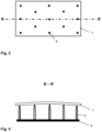
- the support form 4 has a contact surface that is essentially full-surface and is only interrupted by small openings 5 .
- a first glass pane 1 is placed on the contact surface of the support mold 4 .
- the first pane of glass 1 is, for example, a 0.6 mm thick, chemically toughened pane of aluminosilicate glass.
- the convex contact surface of the support mold 4 has a curvature that corresponds to the desired curvature of the laminated glass pane.
- the first glass pane 1 is flat in the initial state, adapts to the contact surface due to its small thickness and the associated flexibility and is bent at ambient temperature without active heating (cold-bent).
- the openings 5 can be connected to a means for generating a negative pressure, for example a fan or a vacuum pump. As a result, a suction effect can be generated, through which the first glass pane 1 is sucked onto the contact surface of the support mold 4 .
- a means for generating a negative pressure for example a fan or a vacuum pump.
- the support mold 4 does not have a large contact surface, but rather a large number of support pins 6.
- the upper ends of the support pins 6 span a curved surface whose curvature corresponds to the desired curvature of the laminated glass pane.
- a first glass pane 1 rests on each support pin 6 essentially at a point, and direct contact over a large area between the support mold and the glass pane 1 is avoided.
- the stack of layers can be glued locally in the area of the support points. In this way, a local bond can be created, so that a kind of pre-composite is created and the layer stack is stabilized in its curved shape and can be removed from the support mold 4 .
- the curvature can be changed by a vertical displacement of the support pins 6 relative to one another.
- the same supporting mold 4 can thus be used to produce different types of laminated glass panes.
- figure 5 shows a cross section through a layer stack for lamination on a support form 4 as in figure 4 .
- the stack of layers includes a thermoplastic film 3 on the first glass pane 1 and a second glass pane 2 on the thermoplastic film 3.
- the thermoplastic film 3 is, for example, a 0.76 mm thick PVB film.
- the second pane of glass 2 is, for example, a 2.1 mm thick pane of soda-lime glass. Due to its thickness, the second glass pane 2 is not sufficiently flexible to be able to be bent cold and is therefore already pre-bent into the final shape using conventional hot bending methods, for example by means of press bending.
- the support form 4 ensures an even contact pressure within the layer stack.
- the subsequent lamination leads to a laminated glass pane with high optical quality and without any critical tendencies towards delamination.
- FIG. 6 shows an exemplary embodiment of the method according to the invention for producing a laminated glass pane using a flow chart.
Landscapes
- Engineering & Computer Science (AREA)
- Mechanical Engineering (AREA)
- Physics & Mathematics (AREA)
- Fluid Mechanics (AREA)
- Chemical & Material Sciences (AREA)
- Chemical Kinetics & Catalysis (AREA)
- General Chemical & Material Sciences (AREA)
- Joining Of Glass To Other Materials (AREA)
- Laminated Bodies (AREA)
Description
- Die Erfindung betrifft ein Verfahren zur Herstellung einer gebogenen Verbundglasscheibe, eine damit hergestellte Verbundglasscheibe und deren Verwendung.
- Verbundglasscheiben sind als Fahrzeugverglasungen gebräuchlich, insbesondere als Windschutzscheiben oder Dachscheiben. Sie bestehen aus zwei Glasscheiben, die über eine thermoplastische Zwischenschicht miteinander verbunden sind. Typische Dicken der Glasscheiben in herkömmlichen Verbundglasscheiben betragen etwa 2 mm. Verglasungen im Fahrzeugbereich sind häufig gebogen. Die relativ dicken Einzelglasscheiben herkömmlicher Verbundglasscheiben werden dabei zunächst auf Erweichungstemperatur erhitzt und gebogen. Nach dem Erstarren weisen sie eine formstabile Biegung auf und werden dann zur Verbundglasscheibe laminiert. Um die Form der beiden zu verbindenden Glasscheiben optimal aufeinander abzustimmen, können sie paarweise aufeinanderliegend, simultan kongruent gebogen werden. Solche Biegeverfahren sind beispielsweise aus
EP 1 836 136 A1 ,EP 1 358 131 A1 ,EP 2 463 247 A1 undEP 2 463 248 A1 bekannt. - Um das Gewicht der Verglasungen zu reduzieren, gibt es Bemühungen, die Dicke der Einzelglasscheiben zu reduzieren, wobei trotzdem die Anforderungen an die Stabilität und Bruchfestigkeit von Fahrzeugscheiben erfüllt werden müssen. So werden vermehrt Verbundglasscheiben vorgeschlagen, die eine dünne Glasscheibe mit einer Dicke von kleiner 1,5 mm oder sogar kleiner 1 mm aufweisen. Lediglich beispielhaft sei dabei auf
EP 2 421 704 A1 ,US 7 070 863 B2 ,DE 3 919 290 A1 ,WO 2015/058885 A1 ,WO 2015/158464 A1 undWO 2016/091435 A1 verwiesen. Zur Steigerung der Stabilität können die dünnen Glasscheiben chemisch vorgespannt sein. - Die Verwendung dünner Glasscheiben macht daran angepasste Herstellungsverfahren erforderlich. Ein klassisches Biegen der dünnen Glasscheiben ist häufig schwierig. Zum einen sind die dünnen Glasscheiben bei der Handhabung bruchanfällig, zum anderen weisen sie oft chemische Zusammensetzungen mit hohen Erweichungstemperaturen auf, was das Biegen energieintensiv macht. Sollen eine dünne und eine dicke Glasscheibe miteinander laminiert werden, so weisen sie zudem in der Regel unterschiedliche Zusammensetzungen auf, wobei für die dicke Glasscheibe das verbreitete und günstige Kalk-Natron-Glas verwenden wird und für die dünne Glasscheibe dagegen eine Glaszusammensetzungen, die hinsichtlich der Eignung zum chemischen Vorspannen ausgewählt ist. Die damit einhergehenden unterschiedlichen Erweichungstemperaturen der beiden Scheiben machen ein paarweises Biegen schwierig oder unmöglich.
- Dünne Glasscheiben sind allerdings bereits bei Raumtemperatur so flexibel, dass sie direkt beim Laminieren kaltgebogen werden können und auf das vorhergehende Biegen in eine formstabile Form verzichtet werden kann. Werden die Glasscheiben und die Zwischenschicht jedoch einfach übereinander gestapelt, so resultiert aus der nicht aufeinander abgestimmten Form der Scheiben und der Rückstellkraft der kaltgebogenen dünnen Glasscheibe ein nicht über die Gesamtfläche konstanter Anpressdruck. Dies verringert die Qualität der Verbundgläser, welche zu optischen Fehlern und Delamination neigen.
-
WO 2015/158464A1 undUS 2014/141206 A1 offenbaren Verfahren zur Herstellung einer Verbundglasscheibe, wobei eine dünne Glasscheibe an die Form einer vorgebogenen dickeren Glasscheibe angepasst und dabei kaltgebogen wird. -
EP 3 078 488 A1 offenbart ein Verfahren zur Herstellung einer Verbundglasscheibe, wobei eine vorgebogene Glasscheibe mittels Saugnäpfen positioniert wird, eine dünnere Glasscheibe mit einem als Pressstempel wirkenden weiteren Unterdruckhalter an die vorgebogene Glasscheibe angepresst wird and anschließend mit Hilfe von IR-Strahlung die Zwischenschicht aufgewärmt wird und die beiden Glasscheiben verbunden werden. - Der vorliegenden Erfindung liegt die Aufgabe zugrunde, ein verbessertes Verfahren zur Herstellung von gebogenen Verbundglasscheiben mit einer dünnen Glasscheibe bereitzustellen. Dabei soll auf ein Heißbiegen der dünnen Glasscheibe verzichtet werden und dennoch eine hohe optische Qualität und mechanische Verbundstabilität gewährleistet werden.
- Die Aufgabe der vorliegenden Erfindung wird erfindungsgemäß durch ein Verfahren zur Herstellung einer Verbundglasscheibe gemäß dem unabhängigen Anspruch 1 gelöst. Bevorzugte Ausführungen gehen aus den Unteransprüchen hervor.
- Die herzustellende Verbundglasscheibe ist zur Abtrennung eines Innenraums, insbesondere eines Fahrzeuginnenraums, von einer äußeren Umgebung vorgesehen. Sie ist also eine Fensterscheibe, die dafür vorgesehen ist, in eine Fensteröffnung, insbesondere eine Fensteröffnung einer Fahrzeugkarosserie, eingesetzt zu werden. Sie ist gebogen und umfasst eine erste Glasscheibe und eine zweite Glasscheibe, die über eine thermoplastische Zwischenschicht miteinander verbunden sind. Die erste Glasscheibe ist dabei eine dünne Glasscheibe mit einer Dicke bis zu 1 mm. Die zweite Glasscheibe weist eine Dicke von größer oder gleich 1,5 mm auf, wie es für herkömmliche Verbundgläser üblich ist. Die dickere zweite Glasscheibe wird klassisch in ihre endgültige Form vorgebogen. Dazu wird sie auf mindestens ihre Erweichungstemperatur erhitzt und dann verformt, das heißt heißgebogen. Die dünne erste Glasscheibe dagegen wird nicht vorgebogen (im Sinne eines Heißbiegens), sondern beim Anordnen des zu laminierenden Schichtstapels deutlich unterhalb ihrer Erweichungstemperatur aus ihrem planen Ausgangszustand durch mechanischen Druck in die gewünschte gebogene Form gebracht, das heißt kaltgebogen. Dabei werden erfindungsgemäß die definierte Form und ein gleichmäßiger Anpressdruck innerhalb des Schichtstapels durch die Verwendung einer Stützform sichergestellt. Die Stützform gibt die gewünschte Biegung vor und wirkt Rückstellkräften der dünnen, elastischen Glasscheibe entgegen, wodurch der Schichtstapel sicher gehandhabt und mit hoher optischer und mechanischer Qualität laminiert werden kann.
- Das erfindungsgemäße Verfahren umfasst mindestens die folgenden Verfahrensschritte:
- Auflegen einer ersten Glasscheibe mit einer Dicke von kleiner oder gleich 1 mm auf eine Stützform, wobei die erste Glasscheibe in eine durch die Stützform festgelegte Form kaltgebogen wird;
- Auflegen mindestens einer thermoplastischen Folie auf die erste Glasscheibe;
- Auflegen einer gebogenen zweiten Glasscheibe mit einer Dicke von größer oder gleich 1,5 mm auf die thermoplastische Folie; und
- Verbinden der ersten Glasscheibe mit der zweiten Glasscheibe über die thermoplastische Folie zu einer Verbundglasscheibe durch Lamination.
- Das Auflegen der Glasscheiben und der Folie aufeinander erfolgt flächig kongruent, wobei es auch möglich ist, eine thermoplastische Folie zu verwenden, die größer ist als die Glasscheiben und über diese übersteht, und die überstehenden Teile der Folie nach dem Laminieren abzuschneiden. Die Verfahrensschritte werden bevorzugt in der angegebenen Reihenfolge durchgeführt. Es sind aber auch Abwandlungen denkbar. So ist es möglich, zunächst die thermoplastische Folie auf die erste Glasscheibe aufzulegen und dann beide gemeinsam mit nach unten weisender erster Glasscheibe auf die Stützform aufzulegen. Ebenso ist es möglich, die zweite Glasscheibe auf die thermoplastische Zwischenschicht aufzulegen und anschließend beide mit nach unten weisender thermoplastischer Folie auf die auf der Stützform befindliche erste Glasscheibe abzulegen. Natürlich muss der gesamte Schichtstapel aus erster Glasscheibe, thermoplastischer Folie und zweiter Glasscheibe auf der Stützform angeordnet sein, bevor er weiter gehandhabt und letztendlich laminiert wird.
- Die Stützform gibt erfindungsgemäß die gewünschte endgültige Form der Verbundglasscheibe vor. Sie weist eine gebogene Kontaktfläche auf oder Kontaktpunkte, die eine gebogene Fläche aufspannen, wobei die Biegung der Kontaktfläche beziehungsweise der aufgespannten Fläche der gewünschten Biegung der Verbundglasscheibe entspricht. Die erste Glasscheibe und die thermoplastische Folie legen sich an die Kontaktfläche oder die Kontaktpunkte an und werden so in die gewünschte Form gebracht. Da diese Biegung der ersten Glasscheibe deutlich unterhalb ihrer Erweichungstemperatur und bevorzugt bei Umgebungstemperatur ohne aktive Beheizung stattfindet, wird der Biegevorgang als Kaltbiegen bezeichnet. Das Kaltbiegen ist aufgrund der Flexibilität und der elastischen Eigenschaft der dünnen Glasscheibe ohne Glasbruch möglich.
- Die Stützform kann grundsätzlich konkav oder konvex ausgebildet sein, ist bevorzugt aber konvex ausgebildet. Das bedeutet, dass die Kontaktfläche der Stützform oder die von den Kontaktpunkten aufgespannte Fläche konvex ist, so dass die zur Stützform hingewandte Oberfläche der ersten Glasscheibe konkav und die von der Stützform abgewandte Oberfläche der ersten Glasscheibe konvex gebogen wird. Mit einer konvexen Stützform wird demnach eine Verbundglasscheibe hergestellt, bei der von der Zwischenschicht abgewandte Oberfläche der dünnen ersten Glasscheibe konkav und die von der Zwischenschicht abgewandte Oberfläche der dickeren zweiten Glasscheibe konvex ausgeformt ist. Da typische Fahrzeugverglasungen eine konvexe außenseitige Oberfläche und eine konkave innenraumseitige Oberfläche aufweisen, ermöglicht die konvexe Stützform folglich Verbundglasscheiben, bei denen die dünne erste Glasscheibe die Innenscheibe ist und die dickere zweite Glasschiebe die Außenscheibe, was üblicherweise aus Gründen der Steinschlag- und Kratzfestigkeit bevorzugt ist. Alternativ ist es aber auch möglich, unter Verwendung einer konkaven Stützform eine Verbundglasscheibe herzustellen, deren Außenscheibe die dünne erste Glasscheibe ist, sollte dies gewünscht sein. Mit Außenscheibe wird im Sinne der Erfindung diejenige Glasscheibe bezeichnet, die dafür vorgesehen ist, in Einbaulage der äußeren Umgebung zugewandt zu sein. Mit Innenscheibe wird diejenige Glasscheibe bezeichnet, die dafür vorgesehen ist, in Einbaulage dem Innenraum zugewandt zu sein. Die Bezeichnungen außenseitig und innenraumseitig sind ebenso zu verstehen.
- Die zweite Glasscheibe weist beim Auflegen auf die Stützform bereits im Wesentlichen ihre endgültige gebogene Form auf. Dazu wird die zweite Glasscheibe vorher in ihrem ursprünglichen planen Ausgangszustand mindestens auf Erweichungstemperatur erhitzt, gebogen und zum Erstarren abgekühlt. Hierzu eignen sich alle gängigen Glasbiegeverfahren, beispielsweise Schwerkraft-, Press- oder Saugbiegen. Die Biegung der zweiten Glasscheibe entspricht im Wesentlichen der Biegung der Kontaktfläche der Stützform.
- Das Anlegen der ersten Glasscheibe an die Stützform kann allein unter Druckeinwirkung erfolgen, entweder nur durch die Gewichtskraft der zweiten Glasscheibe oder zusätzlich durch mechanisch von oben ausgeübten Druck. In einer besonders vorteilhaften Ausführung wird die erste Glasscheibe durch Anlegen eines Unterdrucks an die Stützform angesaugt und dadurch gebogen. Hierzu muss die Stützform mit einem Mittel zur Erzeugung eines Unterdrucks ausgestattet oder geeignet verbindbar sein. Mit Unterdruck wird dabei ein Druck bezeichnet, welcher geringer ist als der Umgebungsdruck. Das kann hinsichtlich der Handhabung oder der Bearbeitungsgeschwindigkeit vorteilhaft sein.
- Die erfindungsgemäße Stützform kann auf verschiedene Arten ausgebildet sein. In einer bevorzugten Ausgestaltung weist die Stützform eine Auflagefläche für die erste Glasscheibe auf. Wenn die erste Glasscheibe auf die Stützform aufgelegt ist, so steht sie im Wesentlichen vollflächig mit der Auflagefläche in Kontakt. Bereiche der Scheibe können von dem Kontakt zur Auflagefläche ausgenommen sein, beispielsweise eine über die Auflagefläche überstehender Randbereich oder Bereiche der Scheibe, die über Unterbrechungen der Auflagefläche angeordnet sind. Solche Unterbrechungen können sich beispielsweise durch Öffnungen, Löcher oder Durchführungen in der Auflagefläche ergeben, über welche die Stützform bevorzugt verfügt, um eine Saugwirkung auf die erste Glasscheibe auszuüben und sie zum Kaltbiegen an die gebogene Auflagefläche anzusaugen. Die Löcher sind mit einem Mittel zur Erzeugung eines Unterdrucks verbunden, durch das die Saugwirkung erzeugt wird. Bevorzugt stehen mindestens 80 % oder sogar mindestens 90 % der Scheibenoberfläche mit der Auflagefläche in Kontakt. Die Auflagefläche kann gepolstert sein, beispielsweise durch einen Überzug oder eine Auflage aus einem Gewebe.
- In einer weiteren bevorzugten Ausgestaltung weist die Stützform eine Mehrzahl von Auflagestiften auf, auf denen die erste Glasscheibe im Wesentlichen punktuell aufliegt. Die Stützform hat dann keine Kontaktfläche im eigentlichen Sinne, sondern eine Mehrzahl von Kontaktpunkten, welche eine gebogene Fläche aufspannen, die der Form der kaltgebogenen Glasscheibe entspricht. Die Kontaktpunkte werden durch den Kontakt der Glasscheibe mit den nach oben weisenden Enden der Kontaktstifte gebildet. Sie sind natürlich keine Punkte im streng mathematischen Sinne, sondern weisen eine endliche Ausdehnung auf, so dass jeder Kontaktstift über eine kleine Kontaktfläche verfügt, die bevorzugt höchstens 10 cm2 beträgt, besonders bevorzugt höchstens 4 cm2. Die Gesamtheit aller Kontaktflächen ist aber wesentlich kleiner als die Ausdehnung der Glasscheibe. Der Anteil der Glasscheibenoberfläche, der mit den Auflagestiften in direktem Kontakt steht, beträgt beispielsweise unter 10 %. Die Auflagestifte können Öffnungen aufweisen, über die eine Saugwirkung auf die Glasscheibe übertragen werden kann, um sie an die Auflagestifte anzusaugen.
- Die Anzahl und die Abstände der Auflagestifte kann vom Fachmann gemäß der Komplexität der Scheibenbiegung geeignet gewählt werden. So sind bei Scheiben mit relativ einfacher Biegung wenige Auflagestifte ausreichend, während komplexere Biegungen mit kleinen lokalen Krümmungsradien und einer Mehrzahl unterschiedlich gekrümmter Bereiche durch eine größere Anzahl von Auflagestiften realisiert werden können. Bevorzugt sollte die Stützform mindestens fünf Auflagestifte aufweisen, wobei vier Auflagestifte den Eckbereichen der Glasscheibe zugeordnet sind und ein Auflagestift der Scheibenmitte zugeordnet ist. Die Anzahl der Auflagestifte hängt von der Größe und Geometrie der Scheibe im Einzelfall ab und kann vom Fachmann entsprechend gewählt werden. Es sollten ausreichend Auflagestifte eingesetzt werden, so dass es nicht zu einer lokalen Gegenbiegung des Glases kommt.
- In einer besonders vorteilhaften Ausgestaltung sind mindestens zwei der Auflagestifte aktiv beheizbar, bevorzugt mehrere Auflagestifte besonders bevorzugt mindestens drei Auflagestifte und ganz besonders bevorzugt mindestens 5 Auflagestifte. Die Auflagestifte können dazu beispielsweise mit Heizspulen ausgestattet sein. Durch die beheizbaren Auflagestifte kann der aufgelegte Schichtstapel im Bereich der Kontaktpunkte erhitzt werden. Bei geeigneter Temperatur kann so eine punktuelle Verklebung der beiden Glasscheiben über die thermoplastische Folie erreicht werden. Durch das Verkleben an zwei Punkten ist der Schichtstapel gegen Verrutschen gesichert. Eine größere Anzahl von beheizbaren Auflagestiften erhöht die Stabilität des Schichtstapels weiter. Es kann dabei vorteilhaft sein, einen zusätzlichen mechanischen Anpressdruck von oben auszuüben. So wird ein Vorverbund hergestellt, der die auf der Stützform erreichte Gestalt des Schichtstapels fixiert. Der Schichtstapel kann dann von der Stützform abgenommen werden und unabhängig von der Stützform, gegebenenfalls nach zusätzlichen Bearbeitungsschritten, zur Verbundglasscheibe laminiert werden.
- Ein Vorteil der Auflagestifte gegenüber einer Auflagefläche besteht darin, dass dieselbe Stützform an verschiedene Scheibenformen angepasst werden kann und daher vielseitiger einsetzbar ist. Dazu sind in einer vorteilhaften Ausgestaltung die Auflagestifte unabhängig voneinander entlang ihrer Erstreckungsrichtung bewegbar. Dadurch kann ihre Höhe verändert werden. Ebenso ist es vorteilhaft, zumindest einen Teil der Auflagestifte oder alle Auflagestifte in der Ebene senkrecht zu ihrer Erstreckungsrichtung bewegbar auszubilden. Dadurch ihre relative Position auf der Scheibe verändert und an die Geometrie der zu erzeugenden Verbundglasscheibe angepasst werden.
- Die Auflagestifte sind daher in einer bevorzugten Ausgestaltung unabhängig voneinander bewegbar, und zwar in ihrer Erstreckungsrichtung und/oder senkrecht zu ihrer Erstreckungsrichtung. Die Stützform ist bevorzugt mit Mitteln zum Bewegen der Auflagestifte ausgestattet, beispielsweise mit Gewindespindeln oder Stellmotoren zum Verschieben der Auflagestifte oder mechanische, hydraulische oder pneumatische Mittel zum Heben und Senken der Auflagestifte. Die Stützform kann auf eine Scheibenform eingestellt werden, indem die Auflagestifte so bewegt werden, dass ihre Kontaktpunkte eine Fläche aufspannen, die der Scheibenform entspricht. Die Bewegung der Auflagestifte kann manuell oder automatisiert erfolgen. So ist es denkbar, dass im Rahmen einer industriellen Massenfertigung die geometrischen Werte der Scheibe in eine Software eingelesen werden, welche ihrerseits die Auflagestifte ansteuert und die Stützform an die Scheibengeometrie anpasst.
- Hinsichtlich des Materials der Stützform, insbesondere der Kontaktfläche beziehungsweise der Auflagestifte, bestehen keine Einschränkungen, solange die Stützform stabil genug ist um den Schichtstapel zu tragen. Da keine Heißbiegung auf der Stützform stattfindet, muss sie auch nicht hitzebeständig sein. Die Materialien können daher vom Fachmann im Einzelfall frei gewählt werden. Geeignete Materialien sind beispielsweise Metalle oder Legierungen wie Stahl oder Aluminium, aber auch Holz oder Kunststoffe.
- Die dünne erste Glasscheibe weist bevorzugt eine Dicke von 0,2 mm bis 1,0 mm auf, besonders bevorzugt 0,4 mm bis 0,7 mm. So dünne Glasscheiben lassen sich gut kaltbiegen. Die erste Glasscheibe kann gehärtet sein, um ihre Bruchfestigkeit zu erhöhen, was die Handhabung beim Kaltbiegen einfacher macht. Da Glasscheiben mit diesen geringen Dicken nicht oder nur sehr schwer thermisch vorgespannt werden können, ist die erste Glasscheibe bevorzugt chemisch vorgespannt.
- Die erste Glasscheibe besteht bevorzugt aus einer Glassorte, die sich gut chemisch vorspannen lässt. Die erste Glasscheibe ist daher bevorzugt aus Aluminosilikatglas gefertigt, insbesondere aus Alkali-Aluminosilikatglas. Das chemische Vorspannen erfolgt durch Austausch kleinerer gegen größere Alkali-Ionen (beispielsweise Natrium- gegen Kaliumionen), wodurch tiefenabhängige Druckspannungen erzeugt werden. Außerdem zeichnet sich diese Glassorte durch hohe Kratzfestigkeit und Härte aus.
- Die zweite Glasscheibe ist bevorzugt aus Kalk-Natron-Glas gefertigt, das als Fensterglas üblich und daher weit verbreitet und vergleichsweise kostengünstig ist. Grundsätzlich kann die zweite Glasscheibe aber auch aus anderen Glassorten gefertigt sein. Die Dicke der zweiten Glasscheibe beträgt bevorzugt von 1,5 mm bis 5 mm. Eine zweite Scheibe mit diesen Dicken ergibt mit der dünnen ersten Glasscheibe ein Verbundglas, welches sich hinsichtlich seiner Stabilität und Gesamtdicke als Fahrzeugverglasung eignet.
- Die thermoplastische Folie enthält bevorzugt Polyvinylbutyral (PVB), Ethylvinylacetat (EVA) oder Polyurethan (PU), besonders bevorzugt PVB. Sie weist bevorzugt eine Dicke von 0,2 bis 2 mm auf, insbesondere 0,5 mm bis 1,6 mm.
- Das Verbinden der Glasscheiben über die thermoplastische Zwischenschicht kann durch alle gängigen Laminationsverfahren erfolgen. Das Laminieren erfolgt typischerweise unter Einwirkung von Temperatur, Druck und/oder Vakuum. Bevorzugt umfasst das Laminieren ein Entlüften des Schichtstapel, wobei ein Unterdruck angelegt wird, um Luft aus dem Zwischenraum zwischen den Glasscheiben und der thermoplastischen Folien zu entfernen, und ein Erwärmen des Schichtstapels, wobei die thermoplastische Folie erweicht und die adhäsive Verbindung zu den Scheibenoberfläche herstellt.
- Zum Entlüften können beispielsweise Vakuumsackverfahren angewendet werden, bei denen der Schichtstapel in einem Sack angeordnet wird, in dem dann ein Unterdruck erzeugt wird. Alternativ können Vakuumringverfahren angewendet werden, bei denen die Seitenkante mit einem umlaufenden Schlauch versehen wird, in dem ein Unterdruck erzeugt wird. Das Erzeugen der endgültigen adhäsiven Verbindung kann in einem Autoklaven erfolgen, in dem der entlüftete Schichtstapel bevorzugt erhitzt und mit Überdruck beaufschlagt wird.
- Das Laminieren kann auf der Stützform erfolgen, wo die gebogene Form stabilisiert wird. Die Scheibe kann aber auch zum Laminieren von der Stützform abgenommen werden, sofern die gebogene Form durch andere Maßnahmen stabilisiert wird, beispielsweise durch das vorstehend beschriebene lokale Verkleben durch beheizte Auflagestifte.
- Das erfindungsgemäße Verfahren kann durchgeführt werden mit einer Vorrichtung zur Herstellung einer Verbundglasscheibe, umfassend eine Stützform, welche die gewünschte endgültige Form der Verbundglasscheibe festlegt, und ein Mittel zum Laminieren der Verbundglasscheibe. Die vorstehend im Zusammenhang mit dem erfindungsgemäßen Verfahren ausgeführten vorteilhaften Ausgestaltungen gelten in gleicher Weise für die Vorrichtung.
- Die erfindungsgemäß hergestellte Verbundglasscheibe kann verwendet werden als Fensterscheibe eines Fahrzeugs, beispielsweise als Windschutzscheibe, Seitenscheibe, Rückscheibe oder Dachscheibe. Dabei bildet die dünne erste Glasscheibe bevorzugt die Innenscheibe der Verbundglasscheibe und ist dem Fahrzeuginnenraum zugewandt, während die dickere zweite Glasscheibe der äußeren Umgebung zugewandt ist.
- Die Erfindung wird anhand einer Zeichnung und Ausführungsbeispielen näher erläutert. Die Zeichnung ist eine schematische Darstellung und nicht maßstabsgetreu. Die Zeichnung schränkt die Erfindung in keiner Weise ein. Es zeigen:
- Fig. 1
- eine Draufsicht auf eine Ausgestaltung der Stützform, die beim erfindungsgemäßen Verfahren verwendet wird, mit der aufgelegten ersten Glasscheibe,
- Fig. 2
- einen Querschnitt durch die Stützform gemäß
Figur 1 , - Fig. 3
- eine Draufsicht auf eine weitere Ausgestaltung der Stützform mit der aufgelegten ersten Glasscheibe,
- Fig. 4
- einen Querschnitt durch die Stützform gemäß
Figur 3 , - Fig. 5
- einen Querschnitt durch die Stützform gemäß
Figur 3 mit dem gesamten aufgelegten Schichtstapel vor dem Laminieren, - Fig. 6
- ein Ausführungsbeispiel des erfindungsgemäßen Verfahrens anhand eines Flussdiagramms.
-
Fig. 1 und Fig. 2 zeigen je ein Detail einer Ausgestaltung der Stützform 4, die beim erfindungsgemäßen Verfahren verwendet wird. Die Stützform 4 weist eine im Wesentlichen vollflächige Kontaktfläche auf, die lediglich durch kleine Öffnungen 5 unterbrochen ist. Eine erste Glasscheibe 1 ist auf der Kontaktfläche der Stützform 4 angeordnet. Die erste Glasscheibe 1 ist beispielsweise eine 0,6 mm dicke, chemisch vorgespannte Scheibe aus Aluminosilikatglas. - Die konvexe Kontaktfläche der Stützform 4 weist eine Krümmung auf, die der gewünschten Krümmung der Verbundglasscheibe entspricht. Die erste Glasscheibe 1 ist im Ausgangszustand plan, passt sich aufgrund ihrer geringen Dicke und der damit verbundenen Flexibilität an die Kontaktfläche an und wird bei Umgebungstemperatur ohne aktive Beheizung gebogen (kaltgebogen).
- Die Öffnungen 5 können mit einem Mittel zur Erzeugung eines Unterdrucks verbunden sein, beispielsweise einem Ventilator oder einer Vakuumpumpe. Dadurch kann eine Saugwirkung erzeugt werden, durch welche die erste Glasscheibe 1 an die Kontaktfläche der Stützform 4 angesaugt wird.
-
Fig. 3 und Fig. 4 zeigen je ein Detail einer weiteren Ausgestaltung der Stützform 4. Die Stützform 4 weist in dieser Ausgestaltung keine großflächige Kontaktfläche auf, sondern eine Vielzahl von Auflagestiften 6. Die oberen Enden der Auflagestifte 6 spannen eine gekrümmte Fläche auf, deren Krümmung der gewünschten Krümmung der Verbundglasscheibe entspricht. Eine erste Glasscheibe 1 liegt auf jedem Auflagestift 6 im Wesentlichen punktuell auf, ein großflächiger direkter Kontakt zwischen Stützform und Glasscheibe 1 wird vermieden. - Sind einige oder alle Auflagestifte 6 beheizbar, so kann der Schichtstapel lokal im Bereich der Auflagepunkte verklebt werden. Dadurch kann eine lokale Verklebung erzeugt werden, so dass eine Art Vorverbund entsteht und der Schichtstapel in seiner gebogenen Form stabilisiert ist und von der Stützform 4 abgenommen werden kann.
- Durch eine vertikale Verschiebung der Auflagestifte 6 gegeneinander kann die Krümmung verändert werden. So kann dieselbe Stützform 4 zur Herstellung verschiedenartiger Verbundglasscheiben verwendet werden.
-
Fig. 5 zeigt einen Querschnitt durch einen Schichtstapel zur Lamination auf einer Stützform 4 wie inFigur 4 . Außer der ersten Glasscheibe 1 auf den Auflagestiften 6 umfasst der Schichtstapel eine thermoplastische Folie 3 auf der ersten Glasscheibe 1 und eine zweite Glasscheibe 2 auf der thermoplastischen Folie 3. Die thermoplastische Folie 3 ist beispielsweise eine 0,76 mm dicke PVB-Folie. Die zweite Glasscheibe 2 ist beispielsweise eine 2,1 mm dicke Scheibe aus Kalk-Natron-Glas. Die zweite Glasscheibe 2 ist aufgrund ihrer Dicke nicht ausreichend flexibel, um kaltgebogen werden zu können und ist daher bereits mittels herkömmlicher Heißbiegeverfahren in die endgültige Form vorgebogen, beispielsweise mittels Pressbiegen. - Durch die Stützform 4 wird ein gleichmäßiger Anpressdruck innerhalb des Schichtstapels sichergestellt. Die anschließende Laminierung führt zu einer Verbundglasscheibe mit hoher optischer Qualität und ohne kritische Tendenzen zur Delamination.
-
Fig. 6 zeigt ein Ausführungsbeispiel des erfindungsgemäßen Verfahrens zur Herstellung einer Verbundglasscheibe anhand eines Flussdiagramms. -
- (1)
- erste Glasscheibe
- (2)
- zweite Glasscheibe
- (3)
- thermoplastische Folie
- (4)
- Stützform
- (5)
- Öffnung in der Auflagefläche der Stützform 4
- (6)
- Auflagestift der Stützform 4
- A-A'
- Schnittlinie
- B-B'
- Schnittlinie
Claims (13)
- Verfahren zur Herstellung einer Verbundglasscheibe, mindestens umfassend:- Auflegen einer ersten Glasscheibe (1) mit einer Dicke von kleiner oder gleich 1 mm auf eine Stützform (4), wobei die erste Glasscheibe (1) in eine durch die Stützform (4) festgelegte Form gebogen wird;- Auflegen mindestens einer thermoplastischen Folie (3) auf die erste Glasscheibe (1);- Auflegen einer gebogenen zweiten Glasscheibe (2) mit einer Dicke von größer oder gleich 1,5 mm auf die thermoplastische Folie (3); und- Verbinden der ersten Glasscheibe (1) mit der zweiten Glasscheibe (2) über die thermoplastische Folie (3) zu einer Verbundglasscheibe durch Lamination.
- Verfahren nach Anspruch 1, wobei die Stützform (4) konvex ausgebildet ist.
- Verfahren nach Anspruch 1 oder 2, wobei die Stützform (4) eine Auflagefläche aufweist, mit der die erste Glasscheibe (1) im Wesentlichen vollflächig in Kontakt steht.
- Verfahren nach Anspruch 1 oder 2, wobei die Stützform (4) eine Mehrzahl von Auflagestiften (6) aufweist, auf denen die erste Glasscheibe (1) im Wesentlichen punktuell aufliegt.
- Verfahren nach Anspruch 4, wobei die Stützform (4) mindestens fünf Auflagestifte (6) aufweist.
- Verfahren nach Anspruch 4 oder 5, wobei mindestens zwei Auflagestifte (6) beheizbar sind.
- Verfahren nach einem der Ansprüche 4 bis 6, wobei die Auflagestifte (6) unabhängig voneinander bewegbar sind.
- Verfahren nach einem der Ansprüche 1 bis 7, wobei die erste Glasscheibe (1) durch Anlegen eines Unterdrucks an die Stützform angesaugt und dadurch gebogen wird.
- Verfahren nach einem der Ansprüche 1 bis 8, wobei die erste Glasscheibe (1) chemisch vorgespannt ist.
- Verfahren nach einem der Ansprüche 1 bis 9, wobei die erste Glasscheibe (1) aus Aluminosilikatglas und die zweite Glasscheibe (2) aus Kalk-Natron-Glas gefertigt ist.
- Verfahren nach einem der Ansprüche 1 bis 10, wobei die thermoplastische Folie (3) Polyvinylbutyral (PVB), Ethylvinylacetat (EVA) oder Polyurethan (PU) enthält.
- Verfahren nach einem der Ansprüche 1 bis 11, wobei die zweite Glasscheibe (2) eine Dicke von 1,5 mm bis 5 mm aufweist.
- Verfahren nach einem der Ansprüche 1 bis 12, wobei die erste Glasscheibe (1) eine Dicke von 0,2 mm bis 1,0 mm aufweist.
Applications Claiming Priority (2)
| Application Number | Priority Date | Filing Date | Title |
|---|---|---|---|
| EP16200376 | 2016-11-24 | ||
| PCT/EP2017/077562 WO2018095693A1 (de) | 2016-11-24 | 2017-10-27 | Verfahren zur herstellung einer gebogenen verbundglasscheibe mit einer dünnen glasscheibe |
Publications (2)
| Publication Number | Publication Date |
|---|---|
| EP3544809A1 EP3544809A1 (de) | 2019-10-02 |
| EP3544809B1 true EP3544809B1 (de) | 2023-06-14 |
Family
ID=57396304
Family Applications (1)
| Application Number | Title | Priority Date | Filing Date |
|---|---|---|---|
| EP17791087.4A Active EP3544809B1 (de) | 2016-11-24 | 2017-10-27 | Verfahren zur herstellung einer gebogenen verbundglasscheibe mit einer dünnen glasscheibe |
Country Status (11)
| Country | Link |
|---|---|
| US (1) | US11192341B2 (de) |
| EP (1) | EP3544809B1 (de) |
| JP (1) | JP6898446B2 (de) |
| KR (1) | KR102244653B1 (de) |
| CN (1) | CN108602324B (de) |
| BR (1) | BR112019000952A2 (de) |
| CA (1) | CA3042439C (de) |
| MA (1) | MA46872A (de) |
| MX (1) | MX2019006016A (de) |
| RU (1) | RU2720685C1 (de) |
| WO (1) | WO2018095693A1 (de) |
Families Citing this family (9)
| Publication number | Priority date | Publication date | Assignee | Title |
|---|---|---|---|---|
| KR102582718B1 (ko) | 2017-02-20 | 2023-09-26 | 코닝 인코포레이티드 | 형상화된 유리 적층물 및 이를 형성하는 방법 |
| CO2017009265A1 (es) * | 2017-09-13 | 2018-01-31 | Agp America Sa | Dispositivo y método para el laminado de vidrio delgado con una prensa de placa |
| WO2019079315A1 (en) | 2017-10-18 | 2019-04-25 | Corning Incorporated | METHODS OF REGULATING SEPARATION BETWEEN GLASSES DURING CO-COATING TO REDUCE FINAL ALIGNMENT DEFECT BETWEEN THESE |
| DE102019208638A1 (de) | 2018-06-20 | 2019-12-24 | Haverkamp Gmbh | Vorrichtung zum flächigen Abstützen einer gekrümmten Glasscheibe beim Herstellen einer gekrümmten Verbundglasscheibe sowie Verbundglasscheibe |
| GB201812147D0 (en) | 2018-07-25 | 2018-09-05 | Pilkington Group Ltd | Process |
| EP3953170A1 (de) * | 2019-04-11 | 2022-02-16 | Corning Incorporated | Verbesserte kantenfestigkeit mittels cte mismatch |
| EP3953172A1 (de) | 2019-04-11 | 2022-02-16 | Corning Incorporated | Verbesserte kantenbelastung mittels differentieller kühlung |
| CN112802918B (zh) * | 2021-02-01 | 2025-06-27 | 常州亚玛顿股份有限公司 | 一种冷弯成型多层玻璃制品、成型工装及其制造方法 |
| EP4566167A1 (de) * | 2022-08-02 | 2025-06-11 | Sunmaxx PVT GmbH | Formkörper und verfahren für ein photovoltaik-modul |
Family Cites Families (27)
| Publication number | Priority date | Publication date | Assignee | Title |
|---|---|---|---|---|
| SU617395A1 (ru) | 1976-09-21 | 1978-07-30 | Саратовский политехнический институт | Установка дл гнуть и закалки листового стекла |
| US4711653A (en) | 1986-12-29 | 1987-12-08 | Ppg Industries, Inc. | Innovative press bending of thermoplastic sheets |
| LU87241A1 (fr) | 1988-06-15 | 1990-02-28 | Glaverbel | Procede d'augmentation de la resistance a la penetration au travers d'une baie vitree et vitrage a resistance a l'effraction renforcee |
| GB9407609D0 (en) * | 1994-04-15 | 1994-06-08 | Pilkington Glass Ltd | Bending and tempering glass sheets |
| JP2000219544A (ja) * | 1999-01-29 | 2000-08-08 | Hanshin Glass Kogyo Kk | 曲面強化合わせガラス用の曲げガラスの製造方法 |
| WO2002007967A1 (en) | 2000-07-20 | 2002-01-31 | Glaverbel | Glazing |
| DE10105200A1 (de) | 2001-02-06 | 2002-08-14 | Saint Gobain | Verfahren und Vorrichtung zum paarweisen Biegen von Glasscheiben |
| FR2880343B1 (fr) | 2004-12-31 | 2007-06-22 | Saint Gobain | Procede de bombage de feuilles de verre par aspiration |
| US20070221313A1 (en) * | 2006-03-23 | 2007-09-27 | Centre Luxembourgeois De Recherches Pour Le Verre Et La Ceramique S.A. (C.R.V.C.) | Method of making reflector for solar collector or the like and corresponding product |
| DE102009017805B4 (de) | 2009-04-20 | 2012-05-16 | Saint-Gobain Sekurit Deutschland Gmbh & Co. Kg | Transparentes Verbundglas und dessen Verwendung |
| WO2011096447A1 (ja) * | 2010-02-03 | 2011-08-11 | 旭硝子株式会社 | ガラス板及びガラス板の製造方法 |
| EP2463247A1 (de) | 2010-12-13 | 2012-06-13 | Saint-Gobain Glass France | Verfahren und Vorrichtung zum Biegen von Scheiben |
| EP2463248A1 (de) | 2010-12-13 | 2012-06-13 | Saint-Gobain Glass France | Verfahren und Vorrichtung zum Biegen von Scheiben |
| US10035331B2 (en) | 2011-06-24 | 2018-07-31 | Corning Incorporated | Light-weight hybrid glass laminates |
| BE1020051A3 (fr) * | 2011-07-04 | 2013-04-02 | Agc Glass Europe | Vitrage automobile. |
| FR2987833B1 (fr) | 2012-03-06 | 2014-03-14 | Saint Gobain | Support de bombage a articulation |
| EP2905267A4 (de) * | 2012-10-02 | 2016-08-17 | Asahi Glass Co Ltd | Verfahren zur herstellung von beschichtetem glas |
| WO2014109237A1 (ja) * | 2013-01-11 | 2014-07-17 | 旭硝子株式会社 | 強化ガラスの製造方法及び製造装置 |
| PL67901Y1 (pl) | 2013-05-10 | 2015-07-31 | Proteh Spółka Z Ograniczoną Odpowiedzialnością | Forma do wytwarzania wielokrzywiznowej wygiętej tafli szkła |
| BR112016005950A2 (pt) | 2013-10-23 | 2017-08-01 | Saint Gobain | ?vidro compósito com pelo menos uma vidraça quimicamente temperada? |
| US20150158275A1 (en) * | 2013-12-10 | 2015-06-11 | Corning Incorporated | Non-yellowing glass laminate structure |
| GB201322240D0 (en) * | 2013-12-16 | 2014-01-29 | Pilkington Group Ltd | Laminated glazing |
| CA2944082A1 (en) * | 2014-04-15 | 2015-10-22 | Saint-Gobain Glass France | Composite glass with thin inner pane |
| MX2017007407A (es) | 2014-12-08 | 2017-11-06 | Saint Gobain | Vidrio compuesto que tiene grosor reducido para una pantalla de visualizacion frontal (hud). |
| US20160297169A1 (en) * | 2015-04-08 | 2016-10-13 | Asahi Glass Company, Limited | Laminated plate |
| JP6849650B2 (ja) * | 2015-07-10 | 2021-03-24 | コーニング インコーポレイテッド | 冷間形成積層体 |
| JP6540386B2 (ja) * | 2015-08-31 | 2019-07-10 | Agc株式会社 | 合わせ板、および合わせ板の製造方法 |
-
2017
- 2017-10-27 WO PCT/EP2017/077562 patent/WO2018095693A1/de not_active Ceased
- 2017-10-27 JP JP2019528115A patent/JP6898446B2/ja not_active Expired - Fee Related
- 2017-10-27 BR BR112019000952A patent/BR112019000952A2/pt active Search and Examination
- 2017-10-27 CA CA3042439A patent/CA3042439C/en active Active
- 2017-10-27 MA MA046872A patent/MA46872A/fr unknown
- 2017-10-27 MX MX2019006016A patent/MX2019006016A/es unknown
- 2017-10-27 EP EP17791087.4A patent/EP3544809B1/de active Active
- 2017-10-27 CN CN201780003130.2A patent/CN108602324B/zh not_active Expired - Fee Related
- 2017-10-27 US US16/463,745 patent/US11192341B2/en not_active Expired - Fee Related
- 2017-10-27 RU RU2019105061A patent/RU2720685C1/ru active
- 2017-10-27 KR KR1020197017778A patent/KR102244653B1/ko not_active Expired - Fee Related
Also Published As
| Publication number | Publication date |
|---|---|
| CA3042439A1 (en) | 2018-05-31 |
| CA3042439C (en) | 2021-02-16 |
| KR20190082946A (ko) | 2019-07-10 |
| US20190389180A1 (en) | 2019-12-26 |
| MA46872A (fr) | 2019-10-02 |
| RU2720685C1 (ru) | 2020-05-12 |
| KR102244653B1 (ko) | 2021-04-26 |
| BR112019000952A2 (pt) | 2019-06-11 |
| WO2018095693A1 (de) | 2018-05-31 |
| CN108602324A (zh) | 2018-09-28 |
| EP3544809A1 (de) | 2019-10-02 |
| JP6898446B2 (ja) | 2021-07-07 |
| JP2020513389A (ja) | 2020-05-14 |
| CN108602324B (zh) | 2021-09-10 |
| MX2019006016A (es) | 2019-08-01 |
| US11192341B2 (en) | 2021-12-07 |
Similar Documents
| Publication | Publication Date | Title |
|---|---|---|
| EP3600882B1 (de) | Vorrichtung und verfahren zum aufnehmen, verformen und ablegen einer dünnen glasscheibe | |
| WO2018095693A1 (de) | Verfahren zur herstellung einer gebogenen verbundglasscheibe mit einer dünnen glasscheibe | |
| DE602004013132T2 (de) | Verfahren zum biegen von glasscheiben durch pressen und saugen | |
| DE69421371T2 (de) | Verfahren und vorrichtung zum formen von glasscheiben und anwendung dieses verfahren zur herstellung von fenstern mit komplexer form | |
| DE60029792T2 (de) | Durchsichtiger laminierter gegenstand | |
| DE69330005T2 (de) | Verfahren zur herstellung eines gekrummten, splittersicheren glaslaminats | |
| DE202016009099U1 (de) | Kaltgeformte Laminate | |
| EP0877664B2 (de) | Verfahren zur herstellung einer von verwerfungsbedingten optischen störungen freien verbundsicherheitsglasscheibe, verwendung einer besonderen trägerfolie für die herstellung der verbundsicherheitsglasscheibe sowie für das verfahren bzw. die verwendung besonders geeignete trägerfolien | |
| EP3212585B1 (de) | Werkzeug für einen glasbiegeprozess | |
| DE202012013654U1 (de) | Leichte Hybrid-Glaslaminate | |
| EP3212584B1 (de) | Biegewerkzeug für glasscheiben | |
| EP3390042B1 (de) | Verfahren zur autoklavfreien lamination einer verbundscheibe | |
| EP3691893A1 (de) | Verbundglasscheibe mit angefastem durchgangsloch | |
| DE112020002902T5 (de) | Laminierte Verglasung mit kleinen Radien in komplexer Form | |
| DE602004002767T2 (de) | Verfahren und vorrichtung zum biegen von glasscheiben | |
| WO2023117576A1 (de) | Windschutzscheibe mit verbessertem aufprallschutz | |
| DE3315330A1 (de) | Verfahren zur herstellung eines gekruemmten glas-kunststoff-laminats | |
| WO2022063575A1 (de) | Verfahren und vorrichtung zum biegen von flachen glasscheiben | |
| EP3697612B1 (de) | Verbessertes ausrichtungs- und verbundverfahren für die herstellung von dünnem verbundglas aus glasscheiben mit fehlender passgenauigkeit | |
| WO2024002826A1 (de) | Verfahren zur herstellung einer fahrzeugverbundscheibe mit verbessertem aufprallschutz | |
| EP2647497A1 (de) | Verfahren zur Herstellung einer gewölbten Verbundscheibe mit vorgeformter Polymerfolie | |
| WO2023110546A1 (de) | Windschutzscheibe mit verbessertem aufprallschutz | |
| DE112018003400T5 (de) | Verfahren zum biegen und laminieren von dünnglas mit einer pressplatte | |
| EP3593994A2 (de) | Vorrichtung zum flächigen abstützen einer gekrümmten glasscheibe beim herstellen einer gekrümmten verbundglasscheibe sowie verbundglasscheibe | |
| EP4146604B1 (de) | Verfahren zum biegen einer glasscheibe mit einem maskierungsbereich und einem durchsichtsbereich |
Legal Events
| Date | Code | Title | Description |
|---|---|---|---|
| STAA | Information on the status of an ep patent application or granted ep patent |
Free format text: STATUS: UNKNOWN |
|
| STAA | Information on the status of an ep patent application or granted ep patent |
Free format text: STATUS: THE INTERNATIONAL PUBLICATION HAS BEEN MADE |
|
| PUAI | Public reference made under article 153(3) epc to a published international application that has entered the european phase |
Free format text: ORIGINAL CODE: 0009012 |
|
| STAA | Information on the status of an ep patent application or granted ep patent |
Free format text: STATUS: REQUEST FOR EXAMINATION WAS MADE |
|
| 17P | Request for examination filed |
Effective date: 20190425 |
|
| AK | Designated contracting states |
Kind code of ref document: A1 Designated state(s): AL AT BE BG CH CY CZ DE DK EE ES FI FR GB GR HR HU IE IS IT LI LT LU LV MC MK MT NL NO PL PT RO RS SE SI SK SM TR |
|
| AX | Request for extension of the european patent |
Extension state: BA ME |
|
| DAX | Request for extension of the european patent (deleted) | ||
| RAV | Requested validation state of the european patent: fee paid |
Extension state: MA Effective date: 20190425 |
|
| RAP1 | Party data changed (applicant data changed or rights of an application transferred) |
Owner name: SAINT-GOBAIN GLASS FRANCE |
|
| STAA | Information on the status of an ep patent application or granted ep patent |
Free format text: STATUS: EXAMINATION IS IN PROGRESS |
|
| 17Q | First examination report despatched |
Effective date: 20220816 |
|
| GRAP | Despatch of communication of intention to grant a patent |
Free format text: ORIGINAL CODE: EPIDOSNIGR1 |
|
| STAA | Information on the status of an ep patent application or granted ep patent |
Free format text: STATUS: GRANT OF PATENT IS INTENDED |
|
| GRAS | Grant fee paid |
Free format text: ORIGINAL CODE: EPIDOSNIGR3 |
|
| GRAA | (expected) grant |
Free format text: ORIGINAL CODE: 0009210 |
|
| STAA | Information on the status of an ep patent application or granted ep patent |
Free format text: STATUS: THE PATENT HAS BEEN GRANTED |
|
| RIC1 | Information provided on ipc code assigned before grant |
Ipc: C03C 27/12 20060101ALI20230412BHEP Ipc: B32B 17/10 20060101AFI20230412BHEP |
|
| INTG | Intention to grant announced |
Effective date: 20230502 |
|
| AK | Designated contracting states |
Kind code of ref document: B1 Designated state(s): AL AT BE BG CH CY CZ DE DK EE ES FI FR GB GR HR HU IE IS IT LI LT LU LV MC MK MT NL NO PL PT RO RS SE SI SK SM TR |
|
| REG | Reference to a national code |
Ref country code: CH Ref legal event code: EP |
|
| REG | Reference to a national code |
Ref country code: DE Ref legal event code: R096 Ref document number: 502017014923 Country of ref document: DE |
|
| REG | Reference to a national code |
Ref country code: AT Ref legal event code: REF Ref document number: 1578948 Country of ref document: AT Kind code of ref document: T Effective date: 20230715 |
|
| REG | Reference to a national code |
Ref country code: LT Ref legal event code: MG9D |
|
| REG | Reference to a national code |
Ref country code: NL Ref legal event code: MP Effective date: 20230614 |
|
| PG25 | Lapsed in a contracting state [announced via postgrant information from national office to epo] |
Ref country code: SE Free format text: LAPSE BECAUSE OF FAILURE TO SUBMIT A TRANSLATION OF THE DESCRIPTION OR TO PAY THE FEE WITHIN THE PRESCRIBED TIME-LIMIT Effective date: 20230614 Ref country code: NO Free format text: LAPSE BECAUSE OF FAILURE TO SUBMIT A TRANSLATION OF THE DESCRIPTION OR TO PAY THE FEE WITHIN THE PRESCRIBED TIME-LIMIT Effective date: 20230914 Ref country code: ES Free format text: LAPSE BECAUSE OF FAILURE TO SUBMIT A TRANSLATION OF THE DESCRIPTION OR TO PAY THE FEE WITHIN THE PRESCRIBED TIME-LIMIT Effective date: 20230614 |
|
| PGFP | Annual fee paid to national office [announced via postgrant information from national office to epo] |
Ref country code: GB Payment date: 20230907 Year of fee payment: 7 |
|
| PG25 | Lapsed in a contracting state [announced via postgrant information from national office to epo] |
Ref country code: RS Free format text: LAPSE BECAUSE OF FAILURE TO SUBMIT A TRANSLATION OF THE DESCRIPTION OR TO PAY THE FEE WITHIN THE PRESCRIBED TIME-LIMIT Effective date: 20230614 Ref country code: NL Free format text: LAPSE BECAUSE OF FAILURE TO SUBMIT A TRANSLATION OF THE DESCRIPTION OR TO PAY THE FEE WITHIN THE PRESCRIBED TIME-LIMIT Effective date: 20230614 Ref country code: LV Free format text: LAPSE BECAUSE OF FAILURE TO SUBMIT A TRANSLATION OF THE DESCRIPTION OR TO PAY THE FEE WITHIN THE PRESCRIBED TIME-LIMIT Effective date: 20230614 Ref country code: LT Free format text: LAPSE BECAUSE OF FAILURE TO SUBMIT A TRANSLATION OF THE DESCRIPTION OR TO PAY THE FEE WITHIN THE PRESCRIBED TIME-LIMIT Effective date: 20230614 Ref country code: HR Free format text: LAPSE BECAUSE OF FAILURE TO SUBMIT A TRANSLATION OF THE DESCRIPTION OR TO PAY THE FEE WITHIN THE PRESCRIBED TIME-LIMIT Effective date: 20230614 Ref country code: GR Free format text: LAPSE BECAUSE OF FAILURE TO SUBMIT A TRANSLATION OF THE DESCRIPTION OR TO PAY THE FEE WITHIN THE PRESCRIBED TIME-LIMIT Effective date: 20230915 |
|
| PGFP | Annual fee paid to national office [announced via postgrant information from national office to epo] |
Ref country code: FR Payment date: 20230911 Year of fee payment: 7 |
|
| PG25 | Lapsed in a contracting state [announced via postgrant information from national office to epo] |
Ref country code: FI Free format text: LAPSE BECAUSE OF FAILURE TO SUBMIT A TRANSLATION OF THE DESCRIPTION OR TO PAY THE FEE WITHIN THE PRESCRIBED TIME-LIMIT Effective date: 20230614 |
|
| PG25 | Lapsed in a contracting state [announced via postgrant information from national office to epo] |
Ref country code: SK Free format text: LAPSE BECAUSE OF FAILURE TO SUBMIT A TRANSLATION OF THE DESCRIPTION OR TO PAY THE FEE WITHIN THE PRESCRIBED TIME-LIMIT Effective date: 20230614 |
|
| PG25 | Lapsed in a contracting state [announced via postgrant information from national office to epo] |
Ref country code: IS Free format text: LAPSE BECAUSE OF FAILURE TO SUBMIT A TRANSLATION OF THE DESCRIPTION OR TO PAY THE FEE WITHIN THE PRESCRIBED TIME-LIMIT Effective date: 20231014 |
|
| PG25 | Lapsed in a contracting state [announced via postgrant information from national office to epo] |
Ref country code: SM Free format text: LAPSE BECAUSE OF FAILURE TO SUBMIT A TRANSLATION OF THE DESCRIPTION OR TO PAY THE FEE WITHIN THE PRESCRIBED TIME-LIMIT Effective date: 20230614 Ref country code: SK Free format text: LAPSE BECAUSE OF FAILURE TO SUBMIT A TRANSLATION OF THE DESCRIPTION OR TO PAY THE FEE WITHIN THE PRESCRIBED TIME-LIMIT Effective date: 20230614 Ref country code: RO Free format text: LAPSE BECAUSE OF FAILURE TO SUBMIT A TRANSLATION OF THE DESCRIPTION OR TO PAY THE FEE WITHIN THE PRESCRIBED TIME-LIMIT Effective date: 20230614 Ref country code: PT Free format text: LAPSE BECAUSE OF FAILURE TO SUBMIT A TRANSLATION OF THE DESCRIPTION OR TO PAY THE FEE WITHIN THE PRESCRIBED TIME-LIMIT Effective date: 20231016 Ref country code: IS Free format text: LAPSE BECAUSE OF FAILURE TO SUBMIT A TRANSLATION OF THE DESCRIPTION OR TO PAY THE FEE WITHIN THE PRESCRIBED TIME-LIMIT Effective date: 20231014 Ref country code: EE Free format text: LAPSE BECAUSE OF FAILURE TO SUBMIT A TRANSLATION OF THE DESCRIPTION OR TO PAY THE FEE WITHIN THE PRESCRIBED TIME-LIMIT Effective date: 20230614 Ref country code: CZ Free format text: LAPSE BECAUSE OF FAILURE TO SUBMIT A TRANSLATION OF THE DESCRIPTION OR TO PAY THE FEE WITHIN THE PRESCRIBED TIME-LIMIT Effective date: 20230614 |
|
| PGFP | Annual fee paid to national office [announced via postgrant information from national office to epo] |
Ref country code: DE Payment date: 20230830 Year of fee payment: 7 |
|
| PG25 | Lapsed in a contracting state [announced via postgrant information from national office to epo] |
Ref country code: PL Free format text: LAPSE BECAUSE OF FAILURE TO SUBMIT A TRANSLATION OF THE DESCRIPTION OR TO PAY THE FEE WITHIN THE PRESCRIBED TIME-LIMIT Effective date: 20230614 |
|
| REG | Reference to a national code |
Ref country code: DE Ref legal event code: R097 Ref document number: 502017014923 Country of ref document: DE |
|
| PLBE | No opposition filed within time limit |
Free format text: ORIGINAL CODE: 0009261 |
|
| STAA | Information on the status of an ep patent application or granted ep patent |
Free format text: STATUS: NO OPPOSITION FILED WITHIN TIME LIMIT |
|
| PG25 | Lapsed in a contracting state [announced via postgrant information from national office to epo] |
Ref country code: DK Free format text: LAPSE BECAUSE OF FAILURE TO SUBMIT A TRANSLATION OF THE DESCRIPTION OR TO PAY THE FEE WITHIN THE PRESCRIBED TIME-LIMIT Effective date: 20230614 |
|
| PG25 | Lapsed in a contracting state [announced via postgrant information from national office to epo] |
Ref country code: SI Free format text: LAPSE BECAUSE OF FAILURE TO SUBMIT A TRANSLATION OF THE DESCRIPTION OR TO PAY THE FEE WITHIN THE PRESCRIBED TIME-LIMIT Effective date: 20230614 |
|
| 26N | No opposition filed |
Effective date: 20240315 |
|
| PG25 | Lapsed in a contracting state [announced via postgrant information from national office to epo] |
Ref country code: SI Free format text: LAPSE BECAUSE OF FAILURE TO SUBMIT A TRANSLATION OF THE DESCRIPTION OR TO PAY THE FEE WITHIN THE PRESCRIBED TIME-LIMIT Effective date: 20230614 Ref country code: IT Free format text: LAPSE BECAUSE OF FAILURE TO SUBMIT A TRANSLATION OF THE DESCRIPTION OR TO PAY THE FEE WITHIN THE PRESCRIBED TIME-LIMIT Effective date: 20230614 Ref country code: MC Free format text: LAPSE BECAUSE OF FAILURE TO SUBMIT A TRANSLATION OF THE DESCRIPTION OR TO PAY THE FEE WITHIN THE PRESCRIBED TIME-LIMIT Effective date: 20230614 |
|
| REG | Reference to a national code |
Ref country code: CH Ref legal event code: PL |
|
| REG | Reference to a national code |
Ref country code: BE Ref legal event code: MM Effective date: 20231031 |
|
| PG25 | Lapsed in a contracting state [announced via postgrant information from national office to epo] |
Ref country code: LU Free format text: LAPSE BECAUSE OF NON-PAYMENT OF DUE FEES Effective date: 20231027 |
|
| PG25 | Lapsed in a contracting state [announced via postgrant information from national office to epo] |
Ref country code: LU Free format text: LAPSE BECAUSE OF NON-PAYMENT OF DUE FEES Effective date: 20231027 |
|
| PG25 | Lapsed in a contracting state [announced via postgrant information from national office to epo] |
Ref country code: CH Free format text: LAPSE BECAUSE OF NON-PAYMENT OF DUE FEES Effective date: 20231031 |
|
| PG25 | Lapsed in a contracting state [announced via postgrant information from national office to epo] |
Ref country code: CH Free format text: LAPSE BECAUSE OF NON-PAYMENT OF DUE FEES Effective date: 20231031 |
|
| PG25 | Lapsed in a contracting state [announced via postgrant information from national office to epo] |
Ref country code: BE Free format text: LAPSE BECAUSE OF NON-PAYMENT OF DUE FEES Effective date: 20231031 |
|
| PG25 | Lapsed in a contracting state [announced via postgrant information from national office to epo] |
Ref country code: IE Free format text: LAPSE BECAUSE OF NON-PAYMENT OF DUE FEES Effective date: 20231027 |
|
| PG25 | Lapsed in a contracting state [announced via postgrant information from national office to epo] |
Ref country code: IE Free format text: LAPSE BECAUSE OF NON-PAYMENT OF DUE FEES Effective date: 20231027 |
|
| PG25 | Lapsed in a contracting state [announced via postgrant information from national office to epo] |
Ref country code: BG Free format text: LAPSE BECAUSE OF FAILURE TO SUBMIT A TRANSLATION OF THE DESCRIPTION OR TO PAY THE FEE WITHIN THE PRESCRIBED TIME-LIMIT Effective date: 20230614 |
|
| PG25 | Lapsed in a contracting state [announced via postgrant information from national office to epo] |
Ref country code: BG Free format text: LAPSE BECAUSE OF FAILURE TO SUBMIT A TRANSLATION OF THE DESCRIPTION OR TO PAY THE FEE WITHIN THE PRESCRIBED TIME-LIMIT Effective date: 20230614 |
|
| REG | Reference to a national code |
Ref country code: AT Ref legal event code: MM01 Ref document number: 1578948 Country of ref document: AT Kind code of ref document: T Effective date: 20231027 |
|
| PG25 | Lapsed in a contracting state [announced via postgrant information from national office to epo] |
Ref country code: AT Free format text: LAPSE BECAUSE OF NON-PAYMENT OF DUE FEES Effective date: 20231027 |
|
| PG25 | Lapsed in a contracting state [announced via postgrant information from national office to epo] |
Ref country code: AT Free format text: LAPSE BECAUSE OF NON-PAYMENT OF DUE FEES Effective date: 20231027 |
|
| REG | Reference to a national code |
Ref country code: DE Ref legal event code: R119 Ref document number: 502017014923 Country of ref document: DE |
|
| GBPC | Gb: european patent ceased through non-payment of renewal fee |
Effective date: 20241027 |
|
| PG25 | Lapsed in a contracting state [announced via postgrant information from national office to epo] |
Ref country code: DE Free format text: LAPSE BECAUSE OF NON-PAYMENT OF DUE FEES Effective date: 20250501 |
|
| PG25 | Lapsed in a contracting state [announced via postgrant information from national office to epo] |
Ref country code: GB Free format text: LAPSE BECAUSE OF NON-PAYMENT OF DUE FEES Effective date: 20241027 |
|
| PG25 | Lapsed in a contracting state [announced via postgrant information from national office to epo] |
Ref country code: FR Free format text: LAPSE BECAUSE OF NON-PAYMENT OF DUE FEES Effective date: 20241031 |
|
| PG25 | Lapsed in a contracting state [announced via postgrant information from national office to epo] |
Ref country code: CY Free format text: LAPSE BECAUSE OF FAILURE TO SUBMIT A TRANSLATION OF THE DESCRIPTION OR TO PAY THE FEE WITHIN THE PRESCRIBED TIME-LIMIT; INVALID AB INITIO Effective date: 20171027 |
|
| PG25 | Lapsed in a contracting state [announced via postgrant information from national office to epo] |
Ref country code: HU Free format text: LAPSE BECAUSE OF FAILURE TO SUBMIT A TRANSLATION OF THE DESCRIPTION OR TO PAY THE FEE WITHIN THE PRESCRIBED TIME-LIMIT; INVALID AB INITIO Effective date: 20171027 |
|
| VS25 | Lapsed in a validation state [announced via postgrant information from nat. office to epo] |
Ref country code: MA Free format text: FAILURE TO ELECT DOMICILE IN THE NATIONAL COUNTRY Effective date: 20230915 |
|
| PG25 | Lapsed in a contracting state [announced via postgrant information from national office to epo] |
Ref country code: TR Free format text: LAPSE BECAUSE OF FAILURE TO SUBMIT A TRANSLATION OF THE DESCRIPTION OR TO PAY THE FEE WITHIN THE PRESCRIBED TIME-LIMIT Effective date: 20230614 |