EP3544152B1 - Wasserkraftgenerator mit flexibler statorbefestigung - Google Patents
Wasserkraftgenerator mit flexibler statorbefestigung Download PDFInfo
- Publication number
- EP3544152B1 EP3544152B1 EP19157336.9A EP19157336A EP3544152B1 EP 3544152 B1 EP3544152 B1 EP 3544152B1 EP 19157336 A EP19157336 A EP 19157336A EP 3544152 B1 EP3544152 B1 EP 3544152B1
- Authority
- EP
- European Patent Office
- Prior art keywords
- stator
- stiffening ring
- stator core
- hydro generator
- pressure plate
- Prior art date
- Legal status (The legal status is an assumption and is not a legal conclusion. Google has not performed a legal analysis and makes no representation as to the accuracy of the status listed.)
- Active
Links
Images

Classifications
-
- H—ELECTRICITY
- H02—GENERATION; CONVERSION OR DISTRIBUTION OF ELECTRIC POWER
- H02K—DYNAMO-ELECTRIC MACHINES
- H02K1/00—Details of the magnetic circuit
- H02K1/06—Details of the magnetic circuit characterised by the shape, form or construction
- H02K1/12—Stationary parts of the magnetic circuit
- H02K1/18—Means for mounting or fastening magnetic stationary parts on to, or to, the stator structures
- H02K1/185—Means for mounting or fastening magnetic stationary parts on to, or to, the stator structures to outer stators
-
- H—ELECTRICITY
- H02—GENERATION; CONVERSION OR DISTRIBUTION OF ELECTRIC POWER
- H02K—DYNAMO-ELECTRIC MACHINES
- H02K17/00—Asynchronous induction motors; Asynchronous induction generators
- H02K17/42—Asynchronous induction generators
-
- H—ELECTRICITY
- H02—GENERATION; CONVERSION OR DISTRIBUTION OF ELECTRIC POWER
- H02K—DYNAMO-ELECTRIC MACHINES
- H02K5/00—Casings; Enclosures; Supports
- H02K5/04—Casings or enclosures characterised by the shape, form or construction thereof
- H02K5/16—Means for supporting bearings, e.g. insulating supports or means for fitting bearings in the bearing-shields
- H02K5/161—Means for supporting bearings, e.g. insulating supports or means for fitting bearings in the bearing-shields radially supporting the rotary shaft at both ends of the rotor
-
- H—ELECTRICITY
- H02—GENERATION; CONVERSION OR DISTRIBUTION OF ELECTRIC POWER
- H02K—DYNAMO-ELECTRIC MACHINES
- H02K5/00—Casings; Enclosures; Supports
- H02K5/04—Casings or enclosures characterised by the shape, form or construction thereof
- H02K5/16—Means for supporting bearings, e.g. insulating supports or means for fitting bearings in the bearing-shields
- H02K5/167—Means for supporting bearings, e.g. insulating supports or means for fitting bearings in the bearing-shields using sliding-contact or spherical cap bearings
- H02K5/1672—Means for supporting bearings, e.g. insulating supports or means for fitting bearings in the bearing-shields using sliding-contact or spherical cap bearings radially supporting the rotary shaft at both ends of the rotor
-
- H—ELECTRICITY
- H02—GENERATION; CONVERSION OR DISTRIBUTION OF ELECTRIC POWER
- H02K—DYNAMO-ELECTRIC MACHINES
- H02K7/00—Arrangements for handling mechanical energy structurally associated with dynamo-electric machines, e.g. structural association with mechanical driving motors or auxiliary dynamo-electric machines
- H02K7/18—Structural association of electric generators with mechanical driving motors, e.g. with turbines
- H02K7/1807—Rotary generators
- H02K7/1823—Rotary generators structurally associated with turbines or similar engines
-
- H—ELECTRICITY
- H02—GENERATION; CONVERSION OR DISTRIBUTION OF ELECTRIC POWER
- H02K—DYNAMO-ELECTRIC MACHINES
- H02K2205/00—Specific aspects not provided for in the other groups of this subclass relating to casings, enclosures, supports
- H02K2205/03—Machines characterised by thrust bearings
Definitions
- the subject of this invention is a hydropower generator with a rotor with a vertical axis of rotation and with a stator surrounding the rotor.
- the stator has a stator core containing the stator winding and a stator housing which, among other things, consists of a jacket, frames and strips.
- the stator core is connected to the stator casing by means of frames, the stator casing being placed on a foundation.
- connection between the stator and the foundation must meet several criteria.
- the weight of the stator and, in certain cases, the weight of the rotating parts must be able to be introduced into the foundation via this connection.
- it must also be possible to absorb additional static and dynamic forces or torques through the connection.
- the connection must also allow radial expansion of the stator, since the stator expands radially during operation due to its heating. If such growth is not permitted, undesirable deformations of the laminated stator core and inadmissibly high foundation forces can occur.
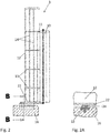
- FIG. 2 shows a schematic embodiment of the stator 3 according to the prior art.
- the strips 11 of the stator housing are connected to the stator casing 12 via annular frames 13, 22.
- the annular frames 13, 22 on the one hand ensure the connection of the stator core 10 to the stator casing 12, but on the other hand they ensure the exact cylindrical shape of the stator core 10 lowest annular frame 22 is directly connected to the stator casing 12.
- the lowermost rib 22 is connected to the foundation 16 via several sliding pieces 24 distributed over the circumference (see FIG Figure 2A ).
- the sliders 24 can slide on base plates 33 in the radial direction and thus allow the stator 3 to grow radially. In the case of different frictional forces on the sliders 24, uneven, undesirable radial deformations of the stator 3 can occur.
- the CN101267141 describes a hydropower generator with a rotor with a vertical axis of rotation according to the preamble of independent claim 1.
- the U.S. 3,988,622 discloses a stator housing in which the laminated core is clamped between two pressure plates and the pressure plate rests slidingly on the foundation.
- the invention is therefore based on the object of providing a hydropower generator in which the stator is connected to the foundation in such a way that radial growth of the stator is permitted and uneven radial deformations of the stator are prevented.
- This object is achieved by a hydropower generator according to claim 1.
- the stator casing is not connected to the foundation via a sliding connection, but rather firmly.
- a stiffening ring is provided to stabilize the stator core. However, this stiffening ring is not directly connected to the stator casing.
- the stator core expands radially during operation. Since the stiffening ring is not directly connected to the stator shell or the foundation, it can expand just like the stator core. According to the invention, the stiffening ring is over Stiffening ribs or connected to the bottom frame via pipes.
- the lower area of the stator casing is designed to be flexible so that it can accommodate the radial expansion of the stator core in the area of the ribs. At the lower end, the stator casing can end with a casing flange and / or stator feet exhibit. The lower end of the stator casing is firmly connected to the foundation. Despite the flexibility of the stator shell, the stator core is always centered.
- stator core is connected to the frames and to the stiffening ring via strips, preferably dovetail strips.
- the stator laminations are then hooked into the strips.
- the stator core preferably rests on an annular or segmented pressure plate and this pressure plate is connected to the stiffening ring.
- the pressure plate can rest on the stiffening ring. If the pressure plate has a larger radius than the stator core and thus projects beyond this, it can also be arranged below the stiffening ring.
- the pressure plate and the stiffening ring can also represent a one-piece component.
- the support bearing for the shaft train is arranged above the stator and that the weight of the rotating masses and any hydraulic axial forces that may occur are introduced into the foundation via the support bearing and the stator casing.
- the ribs are preferably connected to one another via vertical spacers, for example pipes or ribs for absorbing vertical axial forces, the lower ends of the spacers being connected to the foundation via flexible supports.
- the stator housing possibly including the stator core, can also be constructed from several circumferential segments, so that transport in parts is made possible.
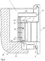
- FIG. 1 shows a section through a generator 1 according to the invention.
- a rotor 2 is arranged within a stator 3.
- the rotor 2 rotates about the vertical axis of rotation 15, the rotor shaft 5 is supported by the support bearing 6 and the two guide bearings 7 and 8.
- the turbine (not shown) is located at the lower end of the rotor shaft 5.
- the stator winding 26 is inserted into slots in the stator core 10.
- the winding head 9 is located at the upper and lower end of the stator core 10.
- the strips 11 of the stator core 10 are connected to the stator casing 12 via frames 13. Vertical spacers 14 for stiffening are arranged between the frames 13.
- the stator core 10 rests here with the pressure plate 21 on an annular stiffening ring 17.
- this stiffening ring 17 is not directly connected to the stator casing 12.
- the stiffening ring 17 is firmly connected to the strips 11; in addition, it is also connected to the lowermost frame 13 via the stiffening ribs 18.
- the stator casing 12 is firmly connected to the foundation 16 via a casing flange 23 and / or stator feet 31.
- vertical forces are introduced into the foundation 16 via the supports 19, which are flexible in the radial direction.
- the arm star 20 rests on the upper end of the stator shell 12 and here carries the guide bearing 8 for the rotor shaft 5. But it is also possible that a support bearing is used in addition to the guide bearing 8, which then the The weight of the rotating masses and the hydraulic axial force absorbs. These forces are then introduced into the foundation 16 via the arm star 20 and the spacers 14 and supports 19.
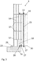
- FIG 3 shows a section through an embodiment of the stator 3 according to the invention.
- the laminated core of the stator core 10 is here clamped together between pressure plates with bolts 25 (stator press bolts).
- the lower stiffening ring 17 also serves as a pressure plate.
- the pressure fingers 30 are arranged between the stator core 10 and the stiffening ring.
- the stiffening ring 17 is also screwed to the stator core 10 with the aid of the bolts 25.
- the stiffening ring 17 is connected to the strips 11 via the screws 27.
- the deformation of the stiffening ring 17 caused by the force of weight can be counteracted by the adjusting screws 28. It is easy to see here that the stiffening ring 17 is not connected to the stator casing 12.
- the stator casing 12 is firmly connected to the foundation 16 via the casing flange 23 with the aid of screws 29 and / or bolts.
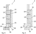
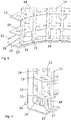
- FIGs 4 and 5 show a further exemplary embodiment of the stator 3.
- the pressure plate 21 rests on the stiffening ring 17.
- Figure 4 shows the stator 3 in the cold state and
- Figure 5 shows the same stator 3 at operating temperature.
- the deformation of the lower part of the stator shell 12 is shown. It can be seen that the stator casing 12 and the supports 19 have been deformed in the lower region of the stator 3. This deformation is caused by the thermally induced radial growth of the stator core 10. You can see here It is good that the stator core 10 can expand over its entire height in the radial direction. The radial displacement is transmitted via the ribs 13 to the stator casing 12, which can also expand.
- stator casing 12 Since the stator casing 12 is flexible in the lower area, it can be firmly connected to the foundation 16 via the screws 29 and / or bolts. The radial expansion is compensated for by the elastic deformation of the stator shell 12, flexible supports 19 that may be present being deformed at the same time. Vertical forces on the stator housing are mainly transmitted through the vertical spacers 14 which run between the frames 13. So that these vertical forces do not have to be completely introduced into the foundation 16 via the stator casing 12, supports 19 can be arranged between the lowermost ribs 13 and the foundation 16 and, like the stator casing 12, can perform a flexible movement in the radial direction. In this application, the term “radial” always relates to the vertical axis of rotation 15.
- FIG. 6 and Figure 7 show two perspective views of part of the stator 3 from FIG Figure 4 .
- the stator core 10 including the pressure plate 21 and the foundation 16 are not shown here.
- the stiffening ring 17 is only connected to the strips 11 and to the stiffening ribs 18.
- the stator casing 12 is polygonal here.
- the strips 11 are connected to the stator casing 12 via the frames 13, and spacers 14, in this example designed as tubes, are also arranged between the frames 13. So that not all of the axial forces over the Housing jacket 12 must be transferred into the foundation 16, supports 19 can be arranged below the lowermost ribs 13. These supports 19, like the stator casing 12, deform in the radial direction when the stator core 10 expands.
- the jacket flange 23 can also be seen here, which is connected to the foundation 16 via the stator feet 31.
- FIG 8 shows an embodiment of the stator according to the invention.
- the pressure plate 21 and the stiffening ring 17 are separate components.
- tubes 32 are provided.
- the strips 11 are connected to the frames 13 and the stiffening ring 17 via tabs 34.
Landscapes
- Engineering & Computer Science (AREA)
- Power Engineering (AREA)
- Iron Core Of Rotating Electric Machines (AREA)
- Motor Or Generator Frames (AREA)
Description
- Den Gegenstand dieser Erfindung bildet ein Wasserkraftgenerator mit einem Rotor mit vertikaler Rotationsachse und mit einem den Rotor umgebenden Stator. Der Stator weist einen die Statorwicklung beinhaltenden Statorkern und ein Statorgehäuse auf, welches unter anderem aus Mantel, Spanten und Leisten besteht. Der Statorkern ist mit Hilfe von Spanten mit dem Statormantel verbunden, wobei der Statormantel auf ein Fundament aufgesetzt ist.
- Bei Wasserkraftgeneratoren mit vertikaler Rotationsachse muss die Verbindung des Stators mit dem Fundament mehrere Kriterien erfüllen. So muss die Gewichtskraft des Stators und in bestimmmten Fällen auch zusätzlich die Gewichtskraft der rotierenden Teile über diese Verbindung in das Fundament eingeleitet werden können. Es müssen aber auch zusätzliche statische und dynamische Kräfte bzw. Drehmomente durch die Verbindung aufgenommen werden können. Zusätzlich muss die Verbindung auch eine radiale Ausdehnung des Stators zulassen, da sich der Stator im Betrieb auf Grund seiner Erwärmung radial ausdehnt. Wird ein derartiges Wachstum nicht zugelassen, kann es unter Umständen zu unerwünschten Verformungen des Statorblechpaketes sowie zu unzulässig hohen Fundamentkräften kommen.
-
Figur 2 zeigt eine schematische Ausführung des Stators 3 nach dem Stand der Technik. Hier sind die Leisten 11 des Statorgehäuses über ringförmige Spanten 13, 22 mit dem Statormantel 12 verbunden. Die ringförmigen Spanten 13, 22 sorgen einerseits für die Verbindung des Statorkerns 10 mit dem Statormantel 12, andererseits gewährleisten sie aber die exakte Zylinderform des Statorkerns 10. Auch die unterste ringförmige Spante 22 ist direkt mit dem Statormantel 12 verbunden. Die unterste Spante 22 ist über mehrere über den Umfang verteilte Gleitstücke 24 mit dem Fundament 16 verbunden (sieheFigur 2A ). Die Gleitstücke 24 können auf Sohlplatten 33 in radialer Richtung gleiten und somit ein radiales Wachstum des Stators 3 zulassen. Im Falle von unterschiedlichen Reibkräften an den Gleitstücken 24 kann es zu ungleichmäßigen, unerwünschten radialen Verformungen des Stators 3 kommen. - Die
CN101267141 beschreibt einen Wasserkraftgenerator mit einem Rotor mit vertikaler Rotationsachse nach der Präambel des unabhängigen Anspruchs 1. - Die
US 3,988,622 offenbart ein Statorgehäuse, bei dem das Blechpaket zwischen zwei Druckplatten eingespannt ist und wobei die unter Druckplatte gleitend am Fundament aufliegt. Der Erfindung liegt daher die Aufgabe zugrunde, einen Wasserkraftgenerator bereitzustellen, bei dem der Stator einerseits so mit dem Fundament verbunden ist, dass ein radiales Wachstum des Stators zugelassen wird und dabei ungleichmäßige radiale Verformungen des Stators unterbunden werden.
Gelöst wird diese Aufgabe durch einen Wasserkraftgenerator gemäß Patentanspruch 1. Erfindungsgemäß ist der Statormantel nicht über eine Gleitverbindung, sondern fest mit dem Fundament verbunden. Im Bereich des unteren Endes des Statorkerns ist ein Versteifungsring zur Stabilisierung des Statorkerns vorgesehen. Dieser Versteifungsring ist jedoch nicht direkt mit dem Statormantel verbunden. Während des Betriebes dehnt sich der Statorkern radial aus. Da der Versteifungsring nicht direkt mit dem Statormantel oder dem Fundament verbunden ist, kann er sich ebenso wie der Statorkern ausdehnen. Erfindungsgemäß ist der Versteifungsring über Aussteifungsrippen oder über Rohre mit der untersten Spante verbunden. Der Statormantel ist im unteren Bereich flexibel ausgeführt, sodass er die radiale Ausdehnung des Statorkerns im Bereich der Spanten mitmacht. Am unteren Ende kann der Statormantel mit einem Mantelflansch enden und/oder Statorfüße aufweisen. Der Statormantel ist am unteren Ende fest mit dem Fundament verbunden. Trotz Nachgiebigkeit des Statormantels ist der Statorkern stets zentriert. - Es ist günstig, wenn der Statorkern über Leisten, vorzugweise Schwalbenschwanzleisten, mit den Spanten und mit dem Versteifungsring verbunden ist. Die Statorbleche sind dann in die Leisten eingehängt.
- Vorzugsweise liegt der Statorkern auf einer ringförmigen oder segmentierten Druckplatte auf und diese Druckplatte ist mit dem Versteifungsring verbunden.
Beispielsweise kann die Druckplatte auf dem Versteifungsring aufliegen. Wenn die Druckplatte einen größeren Radius als der Statorkern aufweist und somit über diesen hinausragt, kann sie auch unterhalb des Versteifungsrings angeordnet sein. - Die Druckplatte und der Versteifungsring können auch ein einstückiges Bauteil darstellen.
- Es ist denkbar, dass das Traglager für den Wellenstrang oberhalb des Stators angeordnet ist und dass die Gewichtskraft der rotierenden Massen und eventuell auftretende hydraulische Axialkräfte über das Traglager und den Statormantel in das Fundament eingeleitet werden.
- Vorzugsweise sind die Spanten über vertikale Distanzstücke, etwa Rohre oder Rippen zur Aufnahme von vertikalen Axialkräften miteinander verbunden, wobei die unteren Enden der Distanzstücke über flexible Stützen mit dem Fundament verbunden sind.
- Das Statorgehäuse, gegebenenfalls samt Statorkern, kann auch aus mehreren Umfangssegmenten aufgebaut sein, sodass ein Transport in Teilstücken ermöglicht wird.
- Im Folgenden wird ein Ausführungsbeispiel der Erfindung anhand von Zeichnungen beschrieben. Es zeigen:
-
Fig. 1 einen schematischen Längsschnitt entlang der Rotorachse durch den erfindungsgemäßen Wasserkraftgenerator; -
Fig. 2 einen Schnitt durch einen Stator einer herkömmlichen Maschine (Stand der Technik); -
Fig. 2A eine Schnittansicht durchFigur 2 entlang der Linie B-B (Stand der Technik); -
Fig. 3 eine Ausführungsform eines erfindungsgemäßen Stators; -
Fig. 4 eine weitere Ausführungsform des erfindungsgemäßen Stators; -
Fig. 5 den erfindungsgemäßen Stator ausFigur 4 im betriebswarmen Zustand; -
Fig. 6 und 7 jeweils eine perspektivische Ansicht des erfindungsgemäßen Stators; -
Fig. 8 eine weitere Ausführungsform des erfindungsgemäßen Stators; -
Figur 1 zeigt einen Schnitt durch einen erfindungsgemäßen Generator 1. Hierbei ist ein Rotor 2 innerhalb eines Stators 3 angeordnet. Der Rotor 2 rotiert um die vertikale Rotationsachse 15, die Rotorwelle 5 wird durch das Traglager 6 und die beiden Führungslager 7 und 8 gelagert. Am unteren Ende der Rotorwelle 5 befindet sich die Turbine (nicht dargestellt). Zwischen dem Rotor 2 und dem Stator 3 befindet sich ein Luftspalt 4. In Nuten des Statorkerns 10 ist die Statorwicklung 26 eingelegt. Am oberen und unteren Ende des Statorkerns 10 befindet sich der Wickelkopf 9. Die Leisten 11 des Statorkerns 10 sind über Spanten 13 mit dem Statormantel 12 verbunden. Zwischen den Spanten 13 sind vertikale Distanzstücke 14 zur Aussteifung angeordnet. - Der Statorkern 10 liegt hier mit der Druckplatte 21 auf einem ringförmigen Versteifungsring 17 auf. Dieser Versteifungsring 17 ist im Gegensatz zu den Spanten 13 nicht direkt mit dem Statormantel 12 verbunden. Der Versteifungsring 17 ist mit den Leisten 11 fest verbunden, zusätzlich ist er auch über die Aussteifungsrippen 18 mit der untersten Spante 13 verbunden.
Der Statormantel 12 ist über einen Mantelflansch 23 und/oder Statorfüße 31 fest mit dem Fundament 16 verbunden. Zusätzlich werden über die in radialer Richtung flexiblen Stützen 19 Vertikalkräfte in das Fundament 16 eingeleitet. - Am oberen Ende des Statormantels 12 liegt der Armstern 20 auf, welcher hier das Führungslager 8 für die Rotorwelle 5 trägt. Es ist aber auch möglich, dass zusätzlich zum Führungslager 8 ein Traglager verwendet wird, das dann die Gewichtskraft der rotierenden Massen und die hydraulische Axialkraft aufnimmt. Diese Kräfte werden dann über den Armstern 20 und die Distanzstücke 14 und Stützen 19 in das Fundament 16 eingeleitet.
-
Figur 3 zeigt einen Schnitt durch ein Ausführungsbeispiel des erfindungsgemäßen Stators 3. Das Blechpaket des Statorkerns 10 ist hier zwischen Druckplatten mit Bolzen 25 (Statorpressbolzen) zusammengespannt. Der untere Versteifungsring 17 dient dabei gleichzeitig als Druckplatte. Zwischen dem Statorkern 10 und dem Versteifungsring sind die Druckfinger 30 angeordnet. Auch der Versteifungsring 17 ist mit Hilfe der Bolzen 25 mit dem Statorkern 10 verschraubt. Über die Schrauben 27 ist der Versteifungsring 17 mit den Leisten 11 verbunden.
Durch die Stellschrauben 28 kann der, durch die Gewichtskraft verursachten Verformung des Versteifungsringes 17 entgegengewirkt werden. Man erkennt hier gut, dass der Versteifungsring 17 nicht mit dem Statormantel 12 verbunden ist. Der Statormantel 12 ist über den Mantelflansch 23 mit Hilfe von Schrauben 29 und/oder Bolzen fest mit dem Fundament 16 verbunden. - Die
Figuren 4 und 5 zeigen ein weiteres Ausführungsbeispiel des Stators 3. Hierbei liegt die Druckplatte 21 auf dem Versteifungsring 17 auf.Figur 4 zeigt den Stator 3 im kalten Zustand undFigur 5 zeigt denselben Stator 3 im betriebswarmen Zustand. InFigur 5 ist die Verformung des unteren Teils des Statormantels 12 dargestellt. Man erkennt, dass im unteren Bereich des Stators 3 der Statormantel 12 und die Stützen 19 verformt wurden. Diese Verformung wird durch das thermisch bedingte radiale Wachstum des Statorkerns 10 hervorgerufen. Man erkennt hier gut, dass sich der Statorkern 10 über seine gesamte Höhe in radialer Richtung ausdehnen kann. Über die Spanten 13 wird die radiale Verschiebung auf den Statormantel 12 übertragen, der sich ebenfalls ausdehnen kann. Da der Statormantel 12 im unteren Bereich flexibel ist, kann er mit dem Fundament 16 über die Schrauben 29 und/oder Bolzen fest verbunden werden. Die radiale Ausdehnung wird durch die elastische Verformung des Statormantels 12 ausgeglichen, wobei allenfalls vorhandene flexible Stützen 19 mitverformt werden. Vertikale Kräfte auf das Statorgehäuse werden vorwiegend durch die vertikalen Distanzstücke 14, die zwischen den Spanten 13 verlaufen, übertragen. Damit diese vertikalen Kräfte nicht vollständig über den Statormantel 12 in das Fundament 16 eingeleitet werden müssen, können zwischen der untersten Spante 13 und dem Fundament 16 Stützen 19 angeordnet sein, die ebenso wie der Statormantel 12 eine flexible Bewegung in radialer Richtung ausführen können. Der Begriff "radial" bezieht sich in dieser Anmeldung immer auf die vertikale Rotationsachse 15. -
Figur 6 und Figur 7 zeigen zwei perspektivische Ansichten eines Teils des Stators 3 ausFigur 4 . Der Statorkern 10 samt Druckplatte 21 und das Fundament 16 sind hier nicht dargestellt. In diesen Darstellungen erkennt man den Versteifungsring 17, der nicht direkt mit dem Statormantel 12 verbunden ist. Der Versteifungsring 17 ist nur mit den Leisten 11 und mit den Aussteifungsrippen 18 verbunden. Der Statormantel 12 ist hier vieleckig ausgeführt. Die Leisten 11 sind über die Spanten 13 mit dem Statormantel 12 verbunden, außerdem sind zwischen den Spanten 13 Distanzstücke 14, in diesem Beispiel als Rohre ausgebildet, angeordnet. Damit nicht die gesamten Axialkräfte über den Gehäusemantel 12 in das Fundament 16 übertragen werden müssen, können unterhalb der untersten Spante 13 Stützen 19 angeordnet sein. Diese Stützen 19 verformen sich ebenso wie der Statormantel 12 in radialer Richtung, wenn sich der Statorkern 10 ausdehnt. Man erkennt hier auch den Mantelflansch 23, der über die Statorfüße 31 mit dem Fundament 16 verbunden ist. -
Figur 8 . zeigt eine Ausführungsform des erfindungsgemäßen Stators. Hier stellen jedoch Druckplatte 21 und Versteifungsring 17 separate Bauteile dar.
Anstatt der Aussteifungsrippen 18 sind Rohre 32 vorgesehen. Die Leisten 11 sind über Laschen 34 mit den Spanten 13 und dem Versteifungsring 17 verbunden.
Claims (10)
- Wasserkraftgenerator (1) mit einem Rotor (2) mit vertikaler Rotationsachse (15) und mit einem Stator (3), wobei der Rotor (2) innerhalb des Stators (3) angeordnet ist, wobei der Stator (3) einen die Statorwicklung (26) beinhaltenden Statorkern (10) und einen vom Statorkern (10) beabstandeten Statormantel (12) aufweist, wobei der Statorkern (10) mit Hilfe von Spanten (13), die sich vertikal zur Rotationsachse (15) erstrecken, mit dem Statormantel (12) verbunden ist, wobei zwischen den Spanten (13) vertikale Distanzstücke (14) zur Aussteifung angeordnet sind und wobei der Statormantel (12) auf ein Fundament (16) aufgesetzt ist, wobei das untere Ende des Statormantels (12) fest mit dem Fundament (16) verbunden ist und im Bereich des unteren Endes des Statorkerns (10) ein Versteifungsring (17) zur Stabilisierung des Statorkerns (10) vorgesehen ist, wobei der Versteifungsring (17) mit dem Statorkern (10) gekoppelt, jedoch vom Statormantel (12) beabstandet ist, sodass der Versteifungsring (17) nicht direkt mit dem Statormantel (12) verbunden ist, dadurch gekennzeichnet, dass der Versteifungsring (17) über Aussteifungsrippen (18) oder über Rohre (32) mit einer untersten Spante (13) verbunden ist.
- Wasserkraftgenerator (1) nach Anspruch 1, dadurch gekennzeichnet, dass der Statorkern (10) über Leisten (11) mit den Spanten (13) und mit dem Versteifungsring (17) verbunden ist.
- Wasserkraftgenerator (1) nach Anspruch 1 oder 2, dadurch gekennzeichnet, dass der Statorkern (10) auf einer ringförmigen oder segmentierten Druckplatte (21) aufliegt und dass die Druckplatte (21) mit dem Versteifungsring (17) verbunden ist.
- Wasserkraftgenerator (1) nach Anspruch 3, dadurch gekennzeichnet, dass die Druckplatte (21) auf dem Versteifungsring (17) aufliegt.
- Wasserkraftgenerator (1) nach Anspruch 3, dadurch gekennzeichnet, dass die Druckplatte (21) unterhalb des Versteifungsringes (17) angeordnet ist und durch Schrauben (27) mit dem Versteifungsring (17) und/oder den Leisten (11) verbunden ist.
- Wasserkraftgenerator (1) nach Anspruch 3, dadurch gekennzeichnet, dass die Druckplatte (21) und der Versteifungsring (17) ein einstückiges Bauteil darstellen.
- Wasserkraftgenerator (1) nach einem der Ansprüche 1 bis 6, dadurch gekennzeichnet, dass ein Traglager oberhalb des Stators (3) angeordnet ist und dass die Gewichtskraft der rotierenden Massen und der hydraulische Axialschub der Turbine über das Traglager und den Statormantel (12) in das Fundament (16) eingeleitet werden.
- Wasserkraftgenerator (1) nach einem der Ansprüche 1 bis 7, dadurch gekennzeichnet, dass die Spanten (13) über vertikale Distanzstücke (14) zur Aufnahme von Axialkräften miteinander verbunden sind und wobei die unteren Enden der Distanzstücke (14) über flexible Stützen (19) mit einem Mantelflansch (23) oder mit Statorfüßen (31) des Statormantels (12) verbunden sind.
- Wasserkraftgenerator (1) nach einem der Ansprüche 1 bis 8, dadurch gekennzeichnet, dass der Statormantel (12) und die Spanten (13) aus mehreren Segmenten aufgebaut sind, sodass ein Transport in Teilstücken ermöglicht wird.
- Wasserkraftgenerator (1) nach einem der Ansprüche 3 bis 9, dadurch gekennzeichnet, dass sich zwischen der Druckplatte (21) und dem Statorkern (10) Druckfinger (30) befinden.
Applications Claiming Priority (1)
| Application Number | Priority Date | Filing Date | Title |
|---|---|---|---|
| ATA50238/2018A AT521062B1 (de) | 2018-03-21 | 2018-03-21 | Wasserkraftgenerator mit flexibler statorbefestigung |
Publications (2)
| Publication Number | Publication Date |
|---|---|
| EP3544152A1 EP3544152A1 (de) | 2019-09-25 |
| EP3544152B1 true EP3544152B1 (de) | 2020-10-28 |
Family
ID=65443695
Family Applications (1)
| Application Number | Title | Priority Date | Filing Date |
|---|---|---|---|
| EP19157336.9A Active EP3544152B1 (de) | 2018-03-21 | 2019-02-15 | Wasserkraftgenerator mit flexibler statorbefestigung |
Country Status (2)
| Country | Link |
|---|---|
| EP (1) | EP3544152B1 (de) |
| AT (1) | AT521062B1 (de) |
Cited By (7)
| Publication number | Priority date | Publication date | Assignee | Title |
|---|---|---|---|---|
| US11834991B2 (en) | 2021-10-15 | 2023-12-05 | Rtx Corporation | Lubrication system for turbine engine electric machine |
| US11867075B2 (en) | 2021-10-15 | 2024-01-09 | Rtx Corporation | Radial outward bearing support for a rotating structure of a turbine engine |
| US11994038B2 (en) | 2021-10-15 | 2024-05-28 | Rtx Corporation | Turbine engine module with electric machine |
| US12000338B2 (en) | 2021-10-15 | 2024-06-04 | Rtx Corporation | Electric machine within a turbine engine |
| US12065974B2 (en) | 2021-10-15 | 2024-08-20 | Rtx Corporation | Double splined coupling for a turbine engine |
| US12152535B2 (en) | 2021-10-15 | 2024-11-26 | Rtx Corporation | Electric machine within a turbine engine |
| US12510026B1 (en) | 2022-02-04 | 2025-12-30 | Rtx Corporation | Lubrication system for aircraft propulsion system with electric machine |
Family Cites Families (8)
| Publication number | Priority date | Publication date | Assignee | Title |
|---|---|---|---|---|
| US3988622A (en) * | 1972-12-11 | 1976-10-26 | Bbc Brown Boveri & Company Limited | Dynamo-electric machine with prestressed laminated stator component |
| JPS52155302A (en) * | 1976-06-19 | 1977-12-23 | Mitsubishi Electric Corp | Laminated iron stator for electric rotary machine |
| DE19960278A1 (de) * | 1999-12-14 | 2001-07-12 | Siemens Ag | Maschinensatz |
| CN2927473Y (zh) * | 2006-07-25 | 2007-07-25 | 四川东风电机厂有限公司 | 一种中高速大容量水轮发电机组 |
| CN101267141A (zh) * | 2008-05-07 | 2008-09-17 | 天津市天发重型水电设备制造有限公司 | 立式水轮发电机无风扇通风冷却装置 |
| CN202696295U (zh) * | 2012-06-04 | 2013-01-23 | 杭州力源发电设备有限公司 | 水轮发电机定子的独立分块式下齿压板结构 |
| US9509182B2 (en) * | 2013-11-25 | 2016-11-29 | General Electric Company | Turbo-generator stator core suspension |
| CN204243926U (zh) * | 2014-12-05 | 2015-04-01 | 东芝水电设备(杭州)有限公司 | 立轴水轮发电机定子铁心压紧结构 |
-
2018
- 2018-03-21 AT ATA50238/2018A patent/AT521062B1/de active
-
2019
- 2019-02-15 EP EP19157336.9A patent/EP3544152B1/de active Active
Non-Patent Citations (1)
| Title |
|---|
| None * |
Cited By (7)
| Publication number | Priority date | Publication date | Assignee | Title |
|---|---|---|---|---|
| US11834991B2 (en) | 2021-10-15 | 2023-12-05 | Rtx Corporation | Lubrication system for turbine engine electric machine |
| US11867075B2 (en) | 2021-10-15 | 2024-01-09 | Rtx Corporation | Radial outward bearing support for a rotating structure of a turbine engine |
| US11994038B2 (en) | 2021-10-15 | 2024-05-28 | Rtx Corporation | Turbine engine module with electric machine |
| US12000338B2 (en) | 2021-10-15 | 2024-06-04 | Rtx Corporation | Electric machine within a turbine engine |
| US12065974B2 (en) | 2021-10-15 | 2024-08-20 | Rtx Corporation | Double splined coupling for a turbine engine |
| US12152535B2 (en) | 2021-10-15 | 2024-11-26 | Rtx Corporation | Electric machine within a turbine engine |
| US12510026B1 (en) | 2022-02-04 | 2025-12-30 | Rtx Corporation | Lubrication system for aircraft propulsion system with electric machine |
Also Published As
| Publication number | Publication date |
|---|---|
| AT521062B1 (de) | 2019-12-15 |
| AT521062A1 (de) | 2019-10-15 |
| EP3544152A1 (de) | 2019-09-25 |
Similar Documents
| Publication | Publication Date | Title |
|---|---|---|
| EP3544152B1 (de) | Wasserkraftgenerator mit flexibler statorbefestigung | |
| EP0432720B1 (de) | Statorwickelkopf, Revisionssatz hierfür und Verfahren zu dessen Umrüstung | |
| EP2508749B1 (de) | Verfahren zum Montieren einer elektrischen Maschine | |
| DE102009044089A1 (de) | Verfahren und Vorrichtung zur Anpassung der thermisch wirksamen Masse und Steifigkeit von verschraubten Teilringen | |
| CH617047A5 (de) | ||
| DE102009017865A1 (de) | Generatoranordnung für Windenergieanlage | |
| DE102008054842A1 (de) | Mischer | |
| EP3894713B1 (de) | Verfahren zum wechseln eines gleitlagerelementes einer rotorlagerung einer windkraftanlage, sowie gondel für eine windkraftanlage | |
| WO2020043421A1 (de) | Lageranordnung eines rotors einer windkraftanlage | |
| DE102012103890A1 (de) | Abstützungsanordnung für das Niederdruckgehäuse einer Dampfturbine | |
| EP3072219A1 (de) | Elektrische maschine mit rahmen und hülle | |
| DE102017119633B4 (de) | Stromgenerator | |
| EP3308449B1 (de) | Statorring für einen elektrischen generator, sowie generator und windenergieanlage mit selbigem | |
| WO2021116016A1 (de) | Lagerhalter zum aufnehmen eines lagers | |
| DE19515260A1 (de) | Vertikalachsige elektrische Wasserkraftmaschine | |
| DE112013001118B4 (de) | Lagervorrichtung | |
| EP3165772A1 (de) | Innenteil für eine turbomaschine, turbomaschine und verfahren zur montage | |
| EP1984998B1 (de) | Vorrichtung zur thermomechanischen entkoppelung von gehäuse und feststehendem teil einer rotationsmaschine | |
| DE2850573C2 (de) | Drehspeicherwärmetauscher | |
| EP3763498B1 (de) | Scheibenschneidmaschine mit motorturm und direkt angetriebenem kreismesser | |
| DE2636167C3 (de) | Anordnung zum Auswuchten von Läufern mit supraleitender Erregerwicklung | |
| EP2836707B1 (de) | Windenergieanlage mit aussenläufergenerator | |
| EP0754856A2 (de) | Rohrturbinenanlage | |
| DE2337030A1 (de) | Einheit von rotor und welle fuer zentrifugalgeblaese | |
| DE602005003727T2 (de) | Dichtungssystem |
Legal Events
| Date | Code | Title | Description |
|---|---|---|---|
| PUAI | Public reference made under article 153(3) epc to a published international application that has entered the european phase |
Free format text: ORIGINAL CODE: 0009012 |
|
| STAA | Information on the status of an ep patent application or granted ep patent |
Free format text: STATUS: THE APPLICATION HAS BEEN PUBLISHED |
|
| AK | Designated contracting states |
Kind code of ref document: A1 Designated state(s): AL AT BE BG CH CY CZ DE DK EE ES FI FR GB GR HR HU IE IS IT LI LT LU LV MC MK MT NL NO PL PT RO RS SE SI SK SM TR |
|
| AX | Request for extension of the european patent |
Extension state: BA ME |
|
| STAA | Information on the status of an ep patent application or granted ep patent |
Free format text: STATUS: REQUEST FOR EXAMINATION WAS MADE |
|
| 17P | Request for examination filed |
Effective date: 20200305 |
|
| RBV | Designated contracting states (corrected) |
Designated state(s): AL AT BE BG CH CY CZ DE DK EE ES FI FR GB GR HR HU IE IS IT LI LT LU LV MC MK MT NL NO PL PT RO RS SE SI SK SM TR |
|
| GRAP | Despatch of communication of intention to grant a patent |
Free format text: ORIGINAL CODE: EPIDOSNIGR1 |
|
| STAA | Information on the status of an ep patent application or granted ep patent |
Free format text: STATUS: GRANT OF PATENT IS INTENDED |
|
| INTG | Intention to grant announced |
Effective date: 20200811 |
|
| GRAS | Grant fee paid |
Free format text: ORIGINAL CODE: EPIDOSNIGR3 |
|
| GRAA | (expected) grant |
Free format text: ORIGINAL CODE: 0009210 |
|
| STAA | Information on the status of an ep patent application or granted ep patent |
Free format text: STATUS: THE PATENT HAS BEEN GRANTED |
|
| AK | Designated contracting states |
Kind code of ref document: B1 Designated state(s): AL AT BE BG CH CY CZ DE DK EE ES FI FR GB GR HR HU IE IS IT LI LT LU LV MC MK MT NL NO PL PT RO RS SE SI SK SM TR |
|
| REG | Reference to a national code |
Ref country code: GB Ref legal event code: FG4D Free format text: NOT ENGLISH |
|
| REG | Reference to a national code |
Ref country code: CH Ref legal event code: EP |
|
| REG | Reference to a national code |
Ref country code: AT Ref legal event code: REF Ref document number: 1329216 Country of ref document: AT Kind code of ref document: T Effective date: 20201115 |
|
| REG | Reference to a national code |
Ref country code: DE Ref legal event code: R096 Ref document number: 502019000328 Country of ref document: DE |
|
| REG | Reference to a national code |
Ref country code: IE Ref legal event code: FG4D Free format text: LANGUAGE OF EP DOCUMENT: GERMAN |
|
| REG | Reference to a national code |
Ref country code: NO Ref legal event code: T2 Effective date: 20201028 |
|
| REG | Reference to a national code |
Ref country code: SE Ref legal event code: TRGR Ref country code: FI Ref legal event code: FGE |
|
| REG | Reference to a national code |
Ref country code: NL Ref legal event code: MP Effective date: 20201028 |
|
| PG25 | Lapsed in a contracting state [announced via postgrant information from national office to epo] |
Ref country code: GR Free format text: LAPSE BECAUSE OF FAILURE TO SUBMIT A TRANSLATION OF THE DESCRIPTION OR TO PAY THE FEE WITHIN THE PRESCRIBED TIME-LIMIT Effective date: 20210129 Ref country code: RS Free format text: LAPSE BECAUSE OF FAILURE TO SUBMIT A TRANSLATION OF THE DESCRIPTION OR TO PAY THE FEE WITHIN THE PRESCRIBED TIME-LIMIT Effective date: 20201028 Ref country code: PT Free format text: LAPSE BECAUSE OF FAILURE TO SUBMIT A TRANSLATION OF THE DESCRIPTION OR TO PAY THE FEE WITHIN THE PRESCRIBED TIME-LIMIT Effective date: 20210301 |
|
| REG | Reference to a national code |
Ref country code: LT Ref legal event code: MG4D |
|
| PG25 | Lapsed in a contracting state [announced via postgrant information from national office to epo] |
Ref country code: ES Free format text: LAPSE BECAUSE OF FAILURE TO SUBMIT A TRANSLATION OF THE DESCRIPTION OR TO PAY THE FEE WITHIN THE PRESCRIBED TIME-LIMIT Effective date: 20201028 Ref country code: LV Free format text: LAPSE BECAUSE OF FAILURE TO SUBMIT A TRANSLATION OF THE DESCRIPTION OR TO PAY THE FEE WITHIN THE PRESCRIBED TIME-LIMIT Effective date: 20201028 Ref country code: PL Free format text: LAPSE BECAUSE OF FAILURE TO SUBMIT A TRANSLATION OF THE DESCRIPTION OR TO PAY THE FEE WITHIN THE PRESCRIBED TIME-LIMIT Effective date: 20201028 Ref country code: IS Free format text: LAPSE BECAUSE OF FAILURE TO SUBMIT A TRANSLATION OF THE DESCRIPTION OR TO PAY THE FEE WITHIN THE PRESCRIBED TIME-LIMIT Effective date: 20210228 Ref country code: BG Free format text: LAPSE BECAUSE OF FAILURE TO SUBMIT A TRANSLATION OF THE DESCRIPTION OR TO PAY THE FEE WITHIN THE PRESCRIBED TIME-LIMIT Effective date: 20210128 |
|
| PG25 | Lapsed in a contracting state [announced via postgrant information from national office to epo] |
Ref country code: HR Free format text: LAPSE BECAUSE OF FAILURE TO SUBMIT A TRANSLATION OF THE DESCRIPTION OR TO PAY THE FEE WITHIN THE PRESCRIBED TIME-LIMIT Effective date: 20201028 Ref country code: NL Free format text: LAPSE BECAUSE OF FAILURE TO SUBMIT A TRANSLATION OF THE DESCRIPTION OR TO PAY THE FEE WITHIN THE PRESCRIBED TIME-LIMIT Effective date: 20201028 |
|
| REG | Reference to a national code |
Ref country code: DE Ref legal event code: R097 Ref document number: 502019000328 Country of ref document: DE |
|
| PG25 | Lapsed in a contracting state [announced via postgrant information from national office to epo] |
Ref country code: LT Free format text: LAPSE BECAUSE OF FAILURE TO SUBMIT A TRANSLATION OF THE DESCRIPTION OR TO PAY THE FEE WITHIN THE PRESCRIBED TIME-LIMIT Effective date: 20201028 Ref country code: RO Free format text: LAPSE BECAUSE OF FAILURE TO SUBMIT A TRANSLATION OF THE DESCRIPTION OR TO PAY THE FEE WITHIN THE PRESCRIBED TIME-LIMIT Effective date: 20201028 Ref country code: EE Free format text: LAPSE BECAUSE OF FAILURE TO SUBMIT A TRANSLATION OF THE DESCRIPTION OR TO PAY THE FEE WITHIN THE PRESCRIBED TIME-LIMIT Effective date: 20201028 Ref country code: SM Free format text: LAPSE BECAUSE OF FAILURE TO SUBMIT A TRANSLATION OF THE DESCRIPTION OR TO PAY THE FEE WITHIN THE PRESCRIBED TIME-LIMIT Effective date: 20201028 Ref country code: SK Free format text: LAPSE BECAUSE OF FAILURE TO SUBMIT A TRANSLATION OF THE DESCRIPTION OR TO PAY THE FEE WITHIN THE PRESCRIBED TIME-LIMIT Effective date: 20201028 Ref country code: CZ Free format text: LAPSE BECAUSE OF FAILURE TO SUBMIT A TRANSLATION OF THE DESCRIPTION OR TO PAY THE FEE WITHIN THE PRESCRIBED TIME-LIMIT Effective date: 20201028 |
|
| PG25 | Lapsed in a contracting state [announced via postgrant information from national office to epo] |
Ref country code: DK Free format text: LAPSE BECAUSE OF FAILURE TO SUBMIT A TRANSLATION OF THE DESCRIPTION OR TO PAY THE FEE WITHIN THE PRESCRIBED TIME-LIMIT Effective date: 20201028 |
|
| PLBE | No opposition filed within time limit |
Free format text: ORIGINAL CODE: 0009261 |
|
| STAA | Information on the status of an ep patent application or granted ep patent |
Free format text: STATUS: NO OPPOSITION FILED WITHIN TIME LIMIT |
|
| PG25 | Lapsed in a contracting state [announced via postgrant information from national office to epo] |
Ref country code: MC Free format text: LAPSE BECAUSE OF FAILURE TO SUBMIT A TRANSLATION OF THE DESCRIPTION OR TO PAY THE FEE WITHIN THE PRESCRIBED TIME-LIMIT Effective date: 20201028 |
|
| 26N | No opposition filed |
Effective date: 20210729 |
|
| REG | Reference to a national code |
Ref country code: BE Ref legal event code: MM Effective date: 20210228 |
|
| PG25 | Lapsed in a contracting state [announced via postgrant information from national office to epo] |
Ref country code: IT Free format text: LAPSE BECAUSE OF FAILURE TO SUBMIT A TRANSLATION OF THE DESCRIPTION OR TO PAY THE FEE WITHIN THE PRESCRIBED TIME-LIMIT Effective date: 20201028 Ref country code: LU Free format text: LAPSE BECAUSE OF NON-PAYMENT OF DUE FEES Effective date: 20210215 Ref country code: AL Free format text: LAPSE BECAUSE OF FAILURE TO SUBMIT A TRANSLATION OF THE DESCRIPTION OR TO PAY THE FEE WITHIN THE PRESCRIBED TIME-LIMIT Effective date: 20201028 |
|
| PG25 | Lapsed in a contracting state [announced via postgrant information from national office to epo] |
Ref country code: SI Free format text: LAPSE BECAUSE OF FAILURE TO SUBMIT A TRANSLATION OF THE DESCRIPTION OR TO PAY THE FEE WITHIN THE PRESCRIBED TIME-LIMIT Effective date: 20201028 |
|
| PG25 | Lapsed in a contracting state [announced via postgrant information from national office to epo] |
Ref country code: IE Free format text: LAPSE BECAUSE OF NON-PAYMENT OF DUE FEES Effective date: 20210215 Ref country code: FR Free format text: LAPSE BECAUSE OF NON-PAYMENT OF DUE FEES Effective date: 20210228 |
|
| PG25 | Lapsed in a contracting state [announced via postgrant information from national office to epo] |
Ref country code: IS Free format text: LAPSE BECAUSE OF FAILURE TO SUBMIT A TRANSLATION OF THE DESCRIPTION OR TO PAY THE FEE WITHIN THE PRESCRIBED TIME-LIMIT Effective date: 20210228 |
|
| PG25 | Lapsed in a contracting state [announced via postgrant information from national office to epo] |
Ref country code: BE Free format text: LAPSE BECAUSE OF NON-PAYMENT OF DUE FEES Effective date: 20210228 |
|
| REG | Reference to a national code |
Ref country code: CH Ref legal event code: PL |
|
| PG25 | Lapsed in a contracting state [announced via postgrant information from national office to epo] |
Ref country code: LI Free format text: LAPSE BECAUSE OF NON-PAYMENT OF DUE FEES Effective date: 20220228 Ref country code: CH Free format text: LAPSE BECAUSE OF NON-PAYMENT OF DUE FEES Effective date: 20220228 |
|
| PG25 | Lapsed in a contracting state [announced via postgrant information from national office to epo] |
Ref country code: CY Free format text: LAPSE BECAUSE OF FAILURE TO SUBMIT A TRANSLATION OF THE DESCRIPTION OR TO PAY THE FEE WITHIN THE PRESCRIBED TIME-LIMIT Effective date: 20201028 |
|
| PG25 | Lapsed in a contracting state [announced via postgrant information from national office to epo] |
Ref country code: HU Free format text: LAPSE BECAUSE OF FAILURE TO SUBMIT A TRANSLATION OF THE DESCRIPTION OR TO PAY THE FEE WITHIN THE PRESCRIBED TIME-LIMIT; INVALID AB INITIO Effective date: 20190215 |
|
| GBPC | Gb: european patent ceased through non-payment of renewal fee |
Effective date: 20230215 |
|
| PG25 | Lapsed in a contracting state [announced via postgrant information from national office to epo] |
Ref country code: GB Free format text: LAPSE BECAUSE OF NON-PAYMENT OF DUE FEES Effective date: 20230215 |
|
| PG25 | Lapsed in a contracting state [announced via postgrant information from national office to epo] |
Ref country code: GB Free format text: LAPSE BECAUSE OF NON-PAYMENT OF DUE FEES Effective date: 20230215 |
|
| PG25 | Lapsed in a contracting state [announced via postgrant information from national office to epo] |
Ref country code: MK Free format text: LAPSE BECAUSE OF FAILURE TO SUBMIT A TRANSLATION OF THE DESCRIPTION OR TO PAY THE FEE WITHIN THE PRESCRIBED TIME-LIMIT Effective date: 20201028 |
|
| PG25 | Lapsed in a contracting state [announced via postgrant information from national office to epo] |
Ref country code: MT Free format text: LAPSE BECAUSE OF FAILURE TO SUBMIT A TRANSLATION OF THE DESCRIPTION OR TO PAY THE FEE WITHIN THE PRESCRIBED TIME-LIMIT Effective date: 20201028 |
|
| PGFP | Annual fee paid to national office [announced via postgrant information from national office to epo] |
Ref country code: DE Payment date: 20250218 Year of fee payment: 7 |
|
| PGFP | Annual fee paid to national office [announced via postgrant information from national office to epo] |
Ref country code: FI Payment date: 20250220 Year of fee payment: 7 |
|
| REG | Reference to a national code |
Ref country code: AT Ref legal event code: MM01 Ref document number: 1329216 Country of ref document: AT Kind code of ref document: T Effective date: 20240215 |
|
| PGFP | Annual fee paid to national office [announced via postgrant information from national office to epo] |
Ref country code: SE Payment date: 20250218 Year of fee payment: 7 |
|
| PGFP | Annual fee paid to national office [announced via postgrant information from national office to epo] |
Ref country code: NO Payment date: 20250221 Year of fee payment: 7 |
|
| PG25 | Lapsed in a contracting state [announced via postgrant information from national office to epo] |
Ref country code: AT Free format text: LAPSE BECAUSE OF NON-PAYMENT OF DUE FEES Effective date: 20240215 |
|
| PG25 | Lapsed in a contracting state [announced via postgrant information from national office to epo] |
Ref country code: TR Free format text: LAPSE BECAUSE OF FAILURE TO SUBMIT A TRANSLATION OF THE DESCRIPTION OR TO PAY THE FEE WITHIN THE PRESCRIBED TIME-LIMIT Effective date: 20201028 |