EP3544152B1 - Générateur hydraulique à fixation flexible de stator - Google Patents
Générateur hydraulique à fixation flexible de stator Download PDFInfo
- Publication number
- EP3544152B1 EP3544152B1 EP19157336.9A EP19157336A EP3544152B1 EP 3544152 B1 EP3544152 B1 EP 3544152B1 EP 19157336 A EP19157336 A EP 19157336A EP 3544152 B1 EP3544152 B1 EP 3544152B1
- Authority
- EP
- European Patent Office
- Prior art keywords
- stator
- stiffening ring
- stator core
- hydro generator
- pressure plate
- Prior art date
- Legal status (The legal status is an assumption and is not a legal conclusion. Google has not performed a legal analysis and makes no representation as to the accuracy of the status listed.)
- Active
Links
Images

Classifications
-
- H—ELECTRICITY
- H02—GENERATION; CONVERSION OR DISTRIBUTION OF ELECTRIC POWER
- H02K—DYNAMO-ELECTRIC MACHINES
- H02K1/00—Details of the magnetic circuit
- H02K1/06—Details of the magnetic circuit characterised by the shape, form or construction
- H02K1/12—Stationary parts of the magnetic circuit
- H02K1/18—Means for mounting or fastening magnetic stationary parts on to, or to, the stator structures
- H02K1/185—Means for mounting or fastening magnetic stationary parts on to, or to, the stator structures to outer stators
-
- H—ELECTRICITY
- H02—GENERATION; CONVERSION OR DISTRIBUTION OF ELECTRIC POWER
- H02K—DYNAMO-ELECTRIC MACHINES
- H02K17/00—Asynchronous induction motors; Asynchronous induction generators
- H02K17/42—Asynchronous induction generators
-
- H—ELECTRICITY
- H02—GENERATION; CONVERSION OR DISTRIBUTION OF ELECTRIC POWER
- H02K—DYNAMO-ELECTRIC MACHINES
- H02K5/00—Casings; Enclosures; Supports
- H02K5/04—Casings or enclosures characterised by the shape, form or construction thereof
- H02K5/16—Means for supporting bearings, e.g. insulating supports or means for fitting bearings in the bearing-shields
- H02K5/161—Means for supporting bearings, e.g. insulating supports or means for fitting bearings in the bearing-shields radially supporting the rotary shaft at both ends of the rotor
-
- H—ELECTRICITY
- H02—GENERATION; CONVERSION OR DISTRIBUTION OF ELECTRIC POWER
- H02K—DYNAMO-ELECTRIC MACHINES
- H02K5/00—Casings; Enclosures; Supports
- H02K5/04—Casings or enclosures characterised by the shape, form or construction thereof
- H02K5/16—Means for supporting bearings, e.g. insulating supports or means for fitting bearings in the bearing-shields
- H02K5/167—Means for supporting bearings, e.g. insulating supports or means for fitting bearings in the bearing-shields using sliding-contact or spherical cap bearings
- H02K5/1672—Means for supporting bearings, e.g. insulating supports or means for fitting bearings in the bearing-shields using sliding-contact or spherical cap bearings radially supporting the rotary shaft at both ends of the rotor
-
- H—ELECTRICITY
- H02—GENERATION; CONVERSION OR DISTRIBUTION OF ELECTRIC POWER
- H02K—DYNAMO-ELECTRIC MACHINES
- H02K7/00—Arrangements for handling mechanical energy structurally associated with dynamo-electric machines, e.g. structural association with mechanical driving motors or auxiliary dynamo-electric machines
- H02K7/18—Structural association of electric generators with mechanical driving motors, e.g. with turbines
- H02K7/1807—Rotary generators
- H02K7/1823—Rotary generators structurally associated with turbines or similar engines
-
- H—ELECTRICITY
- H02—GENERATION; CONVERSION OR DISTRIBUTION OF ELECTRIC POWER
- H02K—DYNAMO-ELECTRIC MACHINES
- H02K2205/00—Specific aspects not provided for in the other groups of this subclass relating to casings, enclosures, supports
- H02K2205/03—Machines characterised by thrust bearings
Definitions
- the subject of this invention is a hydropower generator with a rotor with a vertical axis of rotation and with a stator surrounding the rotor.
- the stator has a stator core containing the stator winding and a stator housing which, among other things, consists of a jacket, frames and strips.
- the stator core is connected to the stator casing by means of frames, the stator casing being placed on a foundation.
- connection between the stator and the foundation must meet several criteria.
- the weight of the stator and, in certain cases, the weight of the rotating parts must be able to be introduced into the foundation via this connection.
- it must also be possible to absorb additional static and dynamic forces or torques through the connection.
- the connection must also allow radial expansion of the stator, since the stator expands radially during operation due to its heating. If such growth is not permitted, undesirable deformations of the laminated stator core and inadmissibly high foundation forces can occur.
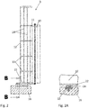
- FIG. 2 shows a schematic embodiment of the stator 3 according to the prior art.
- the strips 11 of the stator housing are connected to the stator casing 12 via annular frames 13, 22.
- the annular frames 13, 22 on the one hand ensure the connection of the stator core 10 to the stator casing 12, but on the other hand they ensure the exact cylindrical shape of the stator core 10 lowest annular frame 22 is directly connected to the stator casing 12.
- the lowermost rib 22 is connected to the foundation 16 via several sliding pieces 24 distributed over the circumference (see FIG Figure 2A ).
- the sliders 24 can slide on base plates 33 in the radial direction and thus allow the stator 3 to grow radially. In the case of different frictional forces on the sliders 24, uneven, undesirable radial deformations of the stator 3 can occur.
- the CN101267141 describes a hydropower generator with a rotor with a vertical axis of rotation according to the preamble of independent claim 1.
- the U.S. 3,988,622 discloses a stator housing in which the laminated core is clamped between two pressure plates and the pressure plate rests slidingly on the foundation.
- the invention is therefore based on the object of providing a hydropower generator in which the stator is connected to the foundation in such a way that radial growth of the stator is permitted and uneven radial deformations of the stator are prevented.
- This object is achieved by a hydropower generator according to claim 1.
- the stator casing is not connected to the foundation via a sliding connection, but rather firmly.
- a stiffening ring is provided to stabilize the stator core. However, this stiffening ring is not directly connected to the stator casing.
- the stator core expands radially during operation. Since the stiffening ring is not directly connected to the stator shell or the foundation, it can expand just like the stator core. According to the invention, the stiffening ring is over Stiffening ribs or connected to the bottom frame via pipes.
- the lower area of the stator casing is designed to be flexible so that it can accommodate the radial expansion of the stator core in the area of the ribs. At the lower end, the stator casing can end with a casing flange and / or stator feet exhibit. The lower end of the stator casing is firmly connected to the foundation. Despite the flexibility of the stator shell, the stator core is always centered.
- stator core is connected to the frames and to the stiffening ring via strips, preferably dovetail strips.
- the stator laminations are then hooked into the strips.
- the stator core preferably rests on an annular or segmented pressure plate and this pressure plate is connected to the stiffening ring.
- the pressure plate can rest on the stiffening ring. If the pressure plate has a larger radius than the stator core and thus projects beyond this, it can also be arranged below the stiffening ring.
- the pressure plate and the stiffening ring can also represent a one-piece component.
- the support bearing for the shaft train is arranged above the stator and that the weight of the rotating masses and any hydraulic axial forces that may occur are introduced into the foundation via the support bearing and the stator casing.
- the ribs are preferably connected to one another via vertical spacers, for example pipes or ribs for absorbing vertical axial forces, the lower ends of the spacers being connected to the foundation via flexible supports.
- the stator housing possibly including the stator core, can also be constructed from several circumferential segments, so that transport in parts is made possible.
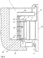
- FIG. 1 shows a section through a generator 1 according to the invention.
- a rotor 2 is arranged within a stator 3.
- the rotor 2 rotates about the vertical axis of rotation 15, the rotor shaft 5 is supported by the support bearing 6 and the two guide bearings 7 and 8.
- the turbine (not shown) is located at the lower end of the rotor shaft 5.
- the stator winding 26 is inserted into slots in the stator core 10.
- the winding head 9 is located at the upper and lower end of the stator core 10.
- the strips 11 of the stator core 10 are connected to the stator casing 12 via frames 13. Vertical spacers 14 for stiffening are arranged between the frames 13.
- the stator core 10 rests here with the pressure plate 21 on an annular stiffening ring 17.
- this stiffening ring 17 is not directly connected to the stator casing 12.
- the stiffening ring 17 is firmly connected to the strips 11; in addition, it is also connected to the lowermost frame 13 via the stiffening ribs 18.
- the stator casing 12 is firmly connected to the foundation 16 via a casing flange 23 and / or stator feet 31.
- vertical forces are introduced into the foundation 16 via the supports 19, which are flexible in the radial direction.
- the arm star 20 rests on the upper end of the stator shell 12 and here carries the guide bearing 8 for the rotor shaft 5. But it is also possible that a support bearing is used in addition to the guide bearing 8, which then the The weight of the rotating masses and the hydraulic axial force absorbs. These forces are then introduced into the foundation 16 via the arm star 20 and the spacers 14 and supports 19.
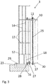
- FIG 3 shows a section through an embodiment of the stator 3 according to the invention.
- the laminated core of the stator core 10 is here clamped together between pressure plates with bolts 25 (stator press bolts).
- the lower stiffening ring 17 also serves as a pressure plate.
- the pressure fingers 30 are arranged between the stator core 10 and the stiffening ring.
- the stiffening ring 17 is also screwed to the stator core 10 with the aid of the bolts 25.
- the stiffening ring 17 is connected to the strips 11 via the screws 27.
- the deformation of the stiffening ring 17 caused by the force of weight can be counteracted by the adjusting screws 28. It is easy to see here that the stiffening ring 17 is not connected to the stator casing 12.
- the stator casing 12 is firmly connected to the foundation 16 via the casing flange 23 with the aid of screws 29 and / or bolts.
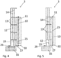
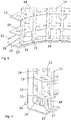
- FIGs 4 and 5 show a further exemplary embodiment of the stator 3.
- the pressure plate 21 rests on the stiffening ring 17.
- Figure 4 shows the stator 3 in the cold state and
- Figure 5 shows the same stator 3 at operating temperature.
- the deformation of the lower part of the stator shell 12 is shown. It can be seen that the stator casing 12 and the supports 19 have been deformed in the lower region of the stator 3. This deformation is caused by the thermally induced radial growth of the stator core 10. You can see here It is good that the stator core 10 can expand over its entire height in the radial direction. The radial displacement is transmitted via the ribs 13 to the stator casing 12, which can also expand.
- stator casing 12 Since the stator casing 12 is flexible in the lower area, it can be firmly connected to the foundation 16 via the screws 29 and / or bolts. The radial expansion is compensated for by the elastic deformation of the stator shell 12, flexible supports 19 that may be present being deformed at the same time. Vertical forces on the stator housing are mainly transmitted through the vertical spacers 14 which run between the frames 13. So that these vertical forces do not have to be completely introduced into the foundation 16 via the stator casing 12, supports 19 can be arranged between the lowermost ribs 13 and the foundation 16 and, like the stator casing 12, can perform a flexible movement in the radial direction. In this application, the term “radial” always relates to the vertical axis of rotation 15.
- FIG. 6 and Figure 7 show two perspective views of part of the stator 3 from FIG Figure 4 .
- the stator core 10 including the pressure plate 21 and the foundation 16 are not shown here.
- the stiffening ring 17 is only connected to the strips 11 and to the stiffening ribs 18.
- the stator casing 12 is polygonal here.
- the strips 11 are connected to the stator casing 12 via the frames 13, and spacers 14, in this example designed as tubes, are also arranged between the frames 13. So that not all of the axial forces over the Housing jacket 12 must be transferred into the foundation 16, supports 19 can be arranged below the lowermost ribs 13. These supports 19, like the stator casing 12, deform in the radial direction when the stator core 10 expands.
- the jacket flange 23 can also be seen here, which is connected to the foundation 16 via the stator feet 31.
- FIG 8 shows an embodiment of the stator according to the invention.
- the pressure plate 21 and the stiffening ring 17 are separate components.
- tubes 32 are provided.
- the strips 11 are connected to the frames 13 and the stiffening ring 17 via tabs 34.
Landscapes
- Engineering & Computer Science (AREA)
- Power Engineering (AREA)
- Iron Core Of Rotating Electric Machines (AREA)
- Motor Or Generator Frames (AREA)
Claims (10)
- Générateur hydraulique (1) comprenant un rotor (2) ayant un axe de rotation vertical (15) et un stator (3), le rotor (2) étant disposé à l'intérieur du stator (3), le stator (3) ayant un noyau de stator (10) contenant l'enroulement de stator (26) et une enveloppe de stator (12) éloignée du noyau de stator (10), le noyau de stator (10) étant relié à l'enveloppe de stator (12) à l'aide de nervures (13) qui s'étendent à la verticale de l'axe de rotation (15), des entretoises verticales (14) servant à apporter de la rigidité étant disposées entre les nervures (13), et l'enveloppe de stator (12) étant posée sur une fondation (16), la partie inférieure de l'enveloppe du stator (12) étant reliée solidement à la fondation (16) et une bague de raidissement (17) étant disposée dans la zone de l'extrémité inférieure du noyau de stator (10) pour stabiliser le noyau de stator (10), la bague de raidissement (17) étant couplée au noyau de stator (10) mais espacée à une certaine distance de l'enveloppe de stator (12) de sorte que la bague de raidissement (17) ne soit pas directement reliée à l'enveloppe de stator (12), caractérisé en ce que la bague de raidissement (17) est reliée à une nervure inférieure (13) par des raidisseurs (18) ou des tubes (32).
- Générateur hydraulique (1) selon la revendication 1, caractérisé en ce que le noyau de stator (10) est relié aux nervures (13) et à la bague de raidissement (17) par des traverses (11).
- Générateur hydraulique (1) selon la revendication 1 ou la revendication 2, caractérisé en ce que le noyau de stator (10) repose sur une plaque de pression segmentée ou annulaire (21) et en ce que la plaque de pression (21) est reliée à la bague de raidissement (17).
- Générateur hydraulique (1) selon la revendication 3, caractérisé en ce que la plaque de pression (21) repose sur la bague de raidissement (17).
- Générateur hydraulique (1) selon la revendication 3, caractérisé en ce que la plaque de pression (21) est disposée sous la bague de raidissement (17) et reliée à la bague de raidissement (17) et/ou aux traverses (11) au moyen de vis (27).
- Générateur hydraulique (1) selon la revendication 3, caractérisé en ce que la plaque de pression (21) et la bague de raidissement (17) forme un élément d'un seul tenant.
- Générateur hydraulique (1) selon l'une des revendications 1 à 6, caractérisé en ce qu'un support est disposé au-dessus du stator (3) et le poids des masses en rotation et la poussée axiale hydraulique de la turbine sont transmis à la fondation (16) par l'intermédiaire du support et de l'enveloppe de stator (12).
- Générateur hydraulique (1) selon l'une quelconque des revendications 1 à 7, caractérisé en ce que les nervures (13) sont reliées l'une à l'autre par des espaceurs verticaux (14) pour absorber la poussée axiale et les extrémités inférieures des espaceurs (14) étant reliées à une bride d'enveloppe (23) ou aux pieds de stator (31) de l'enveloppe de stator (12) par des supports souples (19).
- Générateur hydraulique (1) selon l'une des revendications 1 à 8, caractérisé en ce que l'enveloppe de stator (12) et les nervures (13) sont constituées de plusieurs segments, permettant ainsi un transport par sections.
- Générateur hydraulique (1) selon l'une des revendications 3 à 9, caractérisé en ce que des griffes de serrage (30) se situent entre la plaque de pression (21) et le noyau de stator (10).
Applications Claiming Priority (1)
| Application Number | Priority Date | Filing Date | Title |
|---|---|---|---|
| ATA50238/2018A AT521062B1 (de) | 2018-03-21 | 2018-03-21 | Wasserkraftgenerator mit flexibler statorbefestigung |
Publications (2)
| Publication Number | Publication Date |
|---|---|
| EP3544152A1 EP3544152A1 (fr) | 2019-09-25 |
| EP3544152B1 true EP3544152B1 (fr) | 2020-10-28 |
Family
ID=65443695
Family Applications (1)
| Application Number | Title | Priority Date | Filing Date |
|---|---|---|---|
| EP19157336.9A Active EP3544152B1 (fr) | 2018-03-21 | 2019-02-15 | Générateur hydraulique à fixation flexible de stator |
Country Status (2)
| Country | Link |
|---|---|
| EP (1) | EP3544152B1 (fr) |
| AT (1) | AT521062B1 (fr) |
Cited By (6)
| Publication number | Priority date | Publication date | Assignee | Title |
|---|---|---|---|---|
| US11834991B2 (en) | 2021-10-15 | 2023-12-05 | Rtx Corporation | Lubrication system for turbine engine electric machine |
| US11867075B2 (en) | 2021-10-15 | 2024-01-09 | Rtx Corporation | Radial outward bearing support for a rotating structure of a turbine engine |
| US11994038B2 (en) | 2021-10-15 | 2024-05-28 | Rtx Corporation | Turbine engine module with electric machine |
| US12000338B2 (en) | 2021-10-15 | 2024-06-04 | Rtx Corporation | Electric machine within a turbine engine |
| US12065974B2 (en) | 2021-10-15 | 2024-08-20 | Rtx Corporation | Double splined coupling for a turbine engine |
| US12152535B2 (en) | 2021-10-15 | 2024-11-26 | Rtx Corporation | Electric machine within a turbine engine |
Family Cites Families (8)
| Publication number | Priority date | Publication date | Assignee | Title |
|---|---|---|---|---|
| US3988622A (en) * | 1972-12-11 | 1976-10-26 | Bbc Brown Boveri & Company Limited | Dynamo-electric machine with prestressed laminated stator component |
| JPS52155302A (en) * | 1976-06-19 | 1977-12-23 | Mitsubishi Electric Corp | Laminated iron stator for electric rotary machine |
| DE19960278A1 (de) * | 1999-12-14 | 2001-07-12 | Siemens Ag | Maschinensatz |
| CN2927473Y (zh) * | 2006-07-25 | 2007-07-25 | 四川东风电机厂有限公司 | 一种中高速大容量水轮发电机组 |
| CN101267141A (zh) * | 2008-05-07 | 2008-09-17 | 天津市天发重型水电设备制造有限公司 | 立式水轮发电机无风扇通风冷却装置 |
| CN202696295U (zh) * | 2012-06-04 | 2013-01-23 | 杭州力源发电设备有限公司 | 水轮发电机定子的独立分块式下齿压板结构 |
| US9509182B2 (en) * | 2013-11-25 | 2016-11-29 | General Electric Company | Turbo-generator stator core suspension |
| CN204243926U (zh) * | 2014-12-05 | 2015-04-01 | 东芝水电设备(杭州)有限公司 | 立轴水轮发电机定子铁心压紧结构 |
-
2018
- 2018-03-21 AT ATA50238/2018A patent/AT521062B1/de active
-
2019
- 2019-02-15 EP EP19157336.9A patent/EP3544152B1/fr active Active
Non-Patent Citations (1)
| Title |
|---|
| None * |
Cited By (6)
| Publication number | Priority date | Publication date | Assignee | Title |
|---|---|---|---|---|
| US11834991B2 (en) | 2021-10-15 | 2023-12-05 | Rtx Corporation | Lubrication system for turbine engine electric machine |
| US11867075B2 (en) | 2021-10-15 | 2024-01-09 | Rtx Corporation | Radial outward bearing support for a rotating structure of a turbine engine |
| US11994038B2 (en) | 2021-10-15 | 2024-05-28 | Rtx Corporation | Turbine engine module with electric machine |
| US12000338B2 (en) | 2021-10-15 | 2024-06-04 | Rtx Corporation | Electric machine within a turbine engine |
| US12065974B2 (en) | 2021-10-15 | 2024-08-20 | Rtx Corporation | Double splined coupling for a turbine engine |
| US12152535B2 (en) | 2021-10-15 | 2024-11-26 | Rtx Corporation | Electric machine within a turbine engine |
Also Published As
| Publication number | Publication date |
|---|---|
| EP3544152A1 (fr) | 2019-09-25 |
| AT521062B1 (de) | 2019-12-15 |
| AT521062A1 (de) | 2019-10-15 |
Similar Documents
| Publication | Publication Date | Title |
|---|---|---|
| EP3544152B1 (fr) | Générateur hydraulique à fixation flexible de stator | |
| EP0432720B1 (fr) | Tête de bobinage de stator, ensemble de rechange pour celle-ci et méthode pour son remplacement | |
| EP2508749B1 (fr) | Procédé destiné au montage d'une machine électrique | |
| CH617047A5 (fr) | ||
| DE102009017865A1 (de) | Generatoranordnung für Windenergieanlage | |
| DE102012103890A1 (de) | Abstützungsanordnung für das Niederdruckgehäuse einer Dampfturbine | |
| EP3844410A1 (fr) | Ensemble palier d'un rotor d'éolienne | |
| DE102015114984A1 (de) | Kompressionsbanddistanzpack für einen Statorkern, ein betreffender Stator und Generator | |
| DE102011054858A1 (de) | Tragsystem für eine dynamoelektrische Maschine | |
| DE112016001455T5 (de) | Läufer für einen Asynchronmotor und Asynchronmotor | |
| DE102007060588A1 (de) | Separator mit einem Direktantrieb | |
| WO2015120914A1 (fr) | Machine électrique comprenant un châssis et une enveloppe | |
| DE102017119633B4 (de) | Stromgenerator | |
| EP3308449B1 (fr) | Anneau de stator pour générateur électrique et générateur et éolienne équipé de celui-ci | |
| EP4073395A1 (fr) | Support de palier permettant de recevoir un palier | |
| EP0740402A1 (fr) | Machine hydro-électrique à axe vertical | |
| DE112013001118B4 (de) | Lagervorrichtung | |
| CH452673A (de) | Rotor einer rotierenden elektrischen Maschine | |
| DE3531720A1 (de) | Hydrodynamisches fluidfilmlager | |
| EP3165772A1 (fr) | Partie interne pour une turbomachine, turbomachine et procédé de montage | |
| EP1984998B1 (fr) | Dispositif de decouplage thermomecanique du boitier et de la partie fixe d'une machine en rotation | |
| EP0754856B1 (fr) | Turbine bulbe | |
| DE2850573C2 (de) | Drehspeicherwärmetauscher | |
| EP3763498B1 (fr) | Machine de découpe de tranches pourvue de tour de moteur et de couteau circulaire à commande directe | |
| EP2836707B1 (fr) | Eolienne avec un generateur inversé du type outrunner |
Legal Events
| Date | Code | Title | Description |
|---|---|---|---|
| PUAI | Public reference made under article 153(3) epc to a published international application that has entered the european phase |
Free format text: ORIGINAL CODE: 0009012 |
|
| STAA | Information on the status of an ep patent application or granted ep patent |
Free format text: STATUS: THE APPLICATION HAS BEEN PUBLISHED |
|
| AK | Designated contracting states |
Kind code of ref document: A1 Designated state(s): AL AT BE BG CH CY CZ DE DK EE ES FI FR GB GR HR HU IE IS IT LI LT LU LV MC MK MT NL NO PL PT RO RS SE SI SK SM TR |
|
| AX | Request for extension of the european patent |
Extension state: BA ME |
|
| STAA | Information on the status of an ep patent application or granted ep patent |
Free format text: STATUS: REQUEST FOR EXAMINATION WAS MADE |
|
| 17P | Request for examination filed |
Effective date: 20200305 |
|
| RBV | Designated contracting states (corrected) |
Designated state(s): AL AT BE BG CH CY CZ DE DK EE ES FI FR GB GR HR HU IE IS IT LI LT LU LV MC MK MT NL NO PL PT RO RS SE SI SK SM TR |
|
| GRAP | Despatch of communication of intention to grant a patent |
Free format text: ORIGINAL CODE: EPIDOSNIGR1 |
|
| STAA | Information on the status of an ep patent application or granted ep patent |
Free format text: STATUS: GRANT OF PATENT IS INTENDED |
|
| INTG | Intention to grant announced |
Effective date: 20200811 |
|
| GRAS | Grant fee paid |
Free format text: ORIGINAL CODE: EPIDOSNIGR3 |
|
| GRAA | (expected) grant |
Free format text: ORIGINAL CODE: 0009210 |
|
| STAA | Information on the status of an ep patent application or granted ep patent |
Free format text: STATUS: THE PATENT HAS BEEN GRANTED |
|
| AK | Designated contracting states |
Kind code of ref document: B1 Designated state(s): AL AT BE BG CH CY CZ DE DK EE ES FI FR GB GR HR HU IE IS IT LI LT LU LV MC MK MT NL NO PL PT RO RS SE SI SK SM TR |
|
| REG | Reference to a national code |
Ref country code: GB Ref legal event code: FG4D Free format text: NOT ENGLISH |
|
| REG | Reference to a national code |
Ref country code: CH Ref legal event code: EP |
|
| REG | Reference to a national code |
Ref country code: AT Ref legal event code: REF Ref document number: 1329216 Country of ref document: AT Kind code of ref document: T Effective date: 20201115 |
|
| REG | Reference to a national code |
Ref country code: DE Ref legal event code: R096 Ref document number: 502019000328 Country of ref document: DE |
|
| REG | Reference to a national code |
Ref country code: IE Ref legal event code: FG4D Free format text: LANGUAGE OF EP DOCUMENT: GERMAN |
|
| REG | Reference to a national code |
Ref country code: NO Ref legal event code: T2 Effective date: 20201028 |
|
| REG | Reference to a national code |
Ref country code: SE Ref legal event code: TRGR Ref country code: FI Ref legal event code: FGE |
|
| REG | Reference to a national code |
Ref country code: NL Ref legal event code: MP Effective date: 20201028 |
|
| PG25 | Lapsed in a contracting state [announced via postgrant information from national office to epo] |
Ref country code: GR Free format text: LAPSE BECAUSE OF FAILURE TO SUBMIT A TRANSLATION OF THE DESCRIPTION OR TO PAY THE FEE WITHIN THE PRESCRIBED TIME-LIMIT Effective date: 20210129 Ref country code: RS Free format text: LAPSE BECAUSE OF FAILURE TO SUBMIT A TRANSLATION OF THE DESCRIPTION OR TO PAY THE FEE WITHIN THE PRESCRIBED TIME-LIMIT Effective date: 20201028 Ref country code: PT Free format text: LAPSE BECAUSE OF FAILURE TO SUBMIT A TRANSLATION OF THE DESCRIPTION OR TO PAY THE FEE WITHIN THE PRESCRIBED TIME-LIMIT Effective date: 20210301 |
|
| REG | Reference to a national code |
Ref country code: LT Ref legal event code: MG4D |
|
| PG25 | Lapsed in a contracting state [announced via postgrant information from national office to epo] |
Ref country code: ES Free format text: LAPSE BECAUSE OF FAILURE TO SUBMIT A TRANSLATION OF THE DESCRIPTION OR TO PAY THE FEE WITHIN THE PRESCRIBED TIME-LIMIT Effective date: 20201028 Ref country code: LV Free format text: LAPSE BECAUSE OF FAILURE TO SUBMIT A TRANSLATION OF THE DESCRIPTION OR TO PAY THE FEE WITHIN THE PRESCRIBED TIME-LIMIT Effective date: 20201028 Ref country code: PL Free format text: LAPSE BECAUSE OF FAILURE TO SUBMIT A TRANSLATION OF THE DESCRIPTION OR TO PAY THE FEE WITHIN THE PRESCRIBED TIME-LIMIT Effective date: 20201028 Ref country code: IS Free format text: LAPSE BECAUSE OF FAILURE TO SUBMIT A TRANSLATION OF THE DESCRIPTION OR TO PAY THE FEE WITHIN THE PRESCRIBED TIME-LIMIT Effective date: 20210228 Ref country code: BG Free format text: LAPSE BECAUSE OF FAILURE TO SUBMIT A TRANSLATION OF THE DESCRIPTION OR TO PAY THE FEE WITHIN THE PRESCRIBED TIME-LIMIT Effective date: 20210128 |
|
| PG25 | Lapsed in a contracting state [announced via postgrant information from national office to epo] |
Ref country code: HR Free format text: LAPSE BECAUSE OF FAILURE TO SUBMIT A TRANSLATION OF THE DESCRIPTION OR TO PAY THE FEE WITHIN THE PRESCRIBED TIME-LIMIT Effective date: 20201028 Ref country code: NL Free format text: LAPSE BECAUSE OF FAILURE TO SUBMIT A TRANSLATION OF THE DESCRIPTION OR TO PAY THE FEE WITHIN THE PRESCRIBED TIME-LIMIT Effective date: 20201028 |
|
| REG | Reference to a national code |
Ref country code: DE Ref legal event code: R097 Ref document number: 502019000328 Country of ref document: DE |
|
| PG25 | Lapsed in a contracting state [announced via postgrant information from national office to epo] |
Ref country code: LT Free format text: LAPSE BECAUSE OF FAILURE TO SUBMIT A TRANSLATION OF THE DESCRIPTION OR TO PAY THE FEE WITHIN THE PRESCRIBED TIME-LIMIT Effective date: 20201028 Ref country code: RO Free format text: LAPSE BECAUSE OF FAILURE TO SUBMIT A TRANSLATION OF THE DESCRIPTION OR TO PAY THE FEE WITHIN THE PRESCRIBED TIME-LIMIT Effective date: 20201028 Ref country code: EE Free format text: LAPSE BECAUSE OF FAILURE TO SUBMIT A TRANSLATION OF THE DESCRIPTION OR TO PAY THE FEE WITHIN THE PRESCRIBED TIME-LIMIT Effective date: 20201028 Ref country code: SM Free format text: LAPSE BECAUSE OF FAILURE TO SUBMIT A TRANSLATION OF THE DESCRIPTION OR TO PAY THE FEE WITHIN THE PRESCRIBED TIME-LIMIT Effective date: 20201028 Ref country code: SK Free format text: LAPSE BECAUSE OF FAILURE TO SUBMIT A TRANSLATION OF THE DESCRIPTION OR TO PAY THE FEE WITHIN THE PRESCRIBED TIME-LIMIT Effective date: 20201028 Ref country code: CZ Free format text: LAPSE BECAUSE OF FAILURE TO SUBMIT A TRANSLATION OF THE DESCRIPTION OR TO PAY THE FEE WITHIN THE PRESCRIBED TIME-LIMIT Effective date: 20201028 |
|
| PG25 | Lapsed in a contracting state [announced via postgrant information from national office to epo] |
Ref country code: DK Free format text: LAPSE BECAUSE OF FAILURE TO SUBMIT A TRANSLATION OF THE DESCRIPTION OR TO PAY THE FEE WITHIN THE PRESCRIBED TIME-LIMIT Effective date: 20201028 |
|
| PLBE | No opposition filed within time limit |
Free format text: ORIGINAL CODE: 0009261 |
|
| STAA | Information on the status of an ep patent application or granted ep patent |
Free format text: STATUS: NO OPPOSITION FILED WITHIN TIME LIMIT |
|
| PG25 | Lapsed in a contracting state [announced via postgrant information from national office to epo] |
Ref country code: MC Free format text: LAPSE BECAUSE OF FAILURE TO SUBMIT A TRANSLATION OF THE DESCRIPTION OR TO PAY THE FEE WITHIN THE PRESCRIBED TIME-LIMIT Effective date: 20201028 |
|
| 26N | No opposition filed |
Effective date: 20210729 |
|
| REG | Reference to a national code |
Ref country code: BE Ref legal event code: MM Effective date: 20210228 |
|
| PG25 | Lapsed in a contracting state [announced via postgrant information from national office to epo] |
Ref country code: IT Free format text: LAPSE BECAUSE OF FAILURE TO SUBMIT A TRANSLATION OF THE DESCRIPTION OR TO PAY THE FEE WITHIN THE PRESCRIBED TIME-LIMIT Effective date: 20201028 Ref country code: LU Free format text: LAPSE BECAUSE OF NON-PAYMENT OF DUE FEES Effective date: 20210215 Ref country code: AL Free format text: LAPSE BECAUSE OF FAILURE TO SUBMIT A TRANSLATION OF THE DESCRIPTION OR TO PAY THE FEE WITHIN THE PRESCRIBED TIME-LIMIT Effective date: 20201028 |
|
| PG25 | Lapsed in a contracting state [announced via postgrant information from national office to epo] |
Ref country code: SI Free format text: LAPSE BECAUSE OF FAILURE TO SUBMIT A TRANSLATION OF THE DESCRIPTION OR TO PAY THE FEE WITHIN THE PRESCRIBED TIME-LIMIT Effective date: 20201028 |
|
| PG25 | Lapsed in a contracting state [announced via postgrant information from national office to epo] |
Ref country code: IE Free format text: LAPSE BECAUSE OF NON-PAYMENT OF DUE FEES Effective date: 20210215 Ref country code: FR Free format text: LAPSE BECAUSE OF NON-PAYMENT OF DUE FEES Effective date: 20210228 |
|
| PG25 | Lapsed in a contracting state [announced via postgrant information from national office to epo] |
Ref country code: IS Free format text: LAPSE BECAUSE OF FAILURE TO SUBMIT A TRANSLATION OF THE DESCRIPTION OR TO PAY THE FEE WITHIN THE PRESCRIBED TIME-LIMIT Effective date: 20210228 |
|
| PG25 | Lapsed in a contracting state [announced via postgrant information from national office to epo] |
Ref country code: BE Free format text: LAPSE BECAUSE OF NON-PAYMENT OF DUE FEES Effective date: 20210228 |
|
| REG | Reference to a national code |
Ref country code: CH Ref legal event code: PL |
|
| PG25 | Lapsed in a contracting state [announced via postgrant information from national office to epo] |
Ref country code: LI Free format text: LAPSE BECAUSE OF NON-PAYMENT OF DUE FEES Effective date: 20220228 Ref country code: CH Free format text: LAPSE BECAUSE OF NON-PAYMENT OF DUE FEES Effective date: 20220228 |
|
| PG25 | Lapsed in a contracting state [announced via postgrant information from national office to epo] |
Ref country code: CY Free format text: LAPSE BECAUSE OF FAILURE TO SUBMIT A TRANSLATION OF THE DESCRIPTION OR TO PAY THE FEE WITHIN THE PRESCRIBED TIME-LIMIT Effective date: 20201028 |
|
| PG25 | Lapsed in a contracting state [announced via postgrant information from national office to epo] |
Ref country code: HU Free format text: LAPSE BECAUSE OF FAILURE TO SUBMIT A TRANSLATION OF THE DESCRIPTION OR TO PAY THE FEE WITHIN THE PRESCRIBED TIME-LIMIT; INVALID AB INITIO Effective date: 20190215 |
|
| GBPC | Gb: european patent ceased through non-payment of renewal fee |
Effective date: 20230215 |
|
| PG25 | Lapsed in a contracting state [announced via postgrant information from national office to epo] |
Ref country code: GB Free format text: LAPSE BECAUSE OF NON-PAYMENT OF DUE FEES Effective date: 20230215 |
|
| PG25 | Lapsed in a contracting state [announced via postgrant information from national office to epo] |
Ref country code: GB Free format text: LAPSE BECAUSE OF NON-PAYMENT OF DUE FEES Effective date: 20230215 |
|
| PG25 | Lapsed in a contracting state [announced via postgrant information from national office to epo] |
Ref country code: MK Free format text: LAPSE BECAUSE OF FAILURE TO SUBMIT A TRANSLATION OF THE DESCRIPTION OR TO PAY THE FEE WITHIN THE PRESCRIBED TIME-LIMIT Effective date: 20201028 |
|
| PG25 | Lapsed in a contracting state [announced via postgrant information from national office to epo] |
Ref country code: MT Free format text: LAPSE BECAUSE OF FAILURE TO SUBMIT A TRANSLATION OF THE DESCRIPTION OR TO PAY THE FEE WITHIN THE PRESCRIBED TIME-LIMIT Effective date: 20201028 |
|
| PGFP | Annual fee paid to national office [announced via postgrant information from national office to epo] |
Ref country code: DE Payment date: 20250218 Year of fee payment: 7 |
|
| PGFP | Annual fee paid to national office [announced via postgrant information from national office to epo] |
Ref country code: FI Payment date: 20250220 Year of fee payment: 7 |
|
| REG | Reference to a national code |
Ref country code: AT Ref legal event code: MM01 Ref document number: 1329216 Country of ref document: AT Kind code of ref document: T Effective date: 20240215 |
|
| PGFP | Annual fee paid to national office [announced via postgrant information from national office to epo] |
Ref country code: SE Payment date: 20250218 Year of fee payment: 7 |
|
| PGFP | Annual fee paid to national office [announced via postgrant information from national office to epo] |
Ref country code: NO Payment date: 20250221 Year of fee payment: 7 |
|
| PG25 | Lapsed in a contracting state [announced via postgrant information from national office to epo] |
Ref country code: AT Free format text: LAPSE BECAUSE OF NON-PAYMENT OF DUE FEES Effective date: 20240215 |