EP3544082B9 - Gehäuseanordnung zur aufnahme elektrischer speichermittel und verfahren zur herstellung einer gehäuseanordnung - Google Patents
Gehäuseanordnung zur aufnahme elektrischer speichermittel und verfahren zur herstellung einer gehäuseanordnung Download PDFInfo
- Publication number
- EP3544082B9 EP3544082B9 EP19160921.3A EP19160921A EP3544082B9 EP 3544082 B9 EP3544082 B9 EP 3544082B9 EP 19160921 A EP19160921 A EP 19160921A EP 3544082 B9 EP3544082 B9 EP 3544082B9
- Authority
- EP
- European Patent Office
- Prior art keywords
- formed part
- arrangement
- sheet metal
- housing assembly
- metal blank
- Prior art date
- Legal status (The legal status is an assumption and is not a legal conclusion. Google has not performed a legal analysis and makes no representation as to the accuracy of the status listed.)
- Active
Links
Images

Classifications
-
- B—PERFORMING OPERATIONS; TRANSPORTING
- B60—VEHICLES IN GENERAL
- B60K—ARRANGEMENT OR MOUNTING OF PROPULSION UNITS OR OF TRANSMISSIONS IN VEHICLES; ARRANGEMENT OR MOUNTING OF PLURAL DIVERSE PRIME-MOVERS IN VEHICLES; AUXILIARY DRIVES FOR VEHICLES; INSTRUMENTATION OR DASHBOARDS FOR VEHICLES; ARRANGEMENTS IN CONNECTION WITH COOLING, AIR INTAKE, GAS EXHAUST OR FUEL SUPPLY OF PROPULSION UNITS IN VEHICLES
- B60K1/00—Arrangement or mounting of electrical propulsion units
- B60K1/04—Arrangement or mounting of electrical propulsion units of the electric storage means for propulsion
-
- B—PERFORMING OPERATIONS; TRANSPORTING
- B60—VEHICLES IN GENERAL
- B60L—PROPULSION OF ELECTRICALLY-PROPELLED VEHICLES; SUPPLYING ELECTRIC POWER FOR AUXILIARY EQUIPMENT OF ELECTRICALLY-PROPELLED VEHICLES; ELECTRODYNAMIC BRAKE SYSTEMS FOR VEHICLES IN GENERAL; MAGNETIC SUSPENSION OR LEVITATION FOR VEHICLES; MONITORING OPERATING VARIABLES OF ELECTRICALLY-PROPELLED VEHICLES; ELECTRIC SAFETY DEVICES FOR ELECTRICALLY-PROPELLED VEHICLES
- B60L50/00—Electric propulsion with power supplied within the vehicle
- B60L50/50—Electric propulsion with power supplied within the vehicle using propulsion power supplied by batteries or fuel cells
- B60L50/60—Electric propulsion with power supplied within the vehicle using propulsion power supplied by batteries or fuel cells using power supplied by batteries
- B60L50/66—Arrangements of batteries
-
- H—ELECTRICITY
- H01—ELECTRIC ELEMENTS
- H01M—PROCESSES OR MEANS, e.g. BATTERIES, FOR THE DIRECT CONVERSION OF CHEMICAL ENERGY INTO ELECTRICAL ENERGY
- H01M50/00—Constructional details or processes of manufacture of the non-active parts of electrochemical cells other than fuel cells, e.g. hybrid cells
- H01M50/20—Mountings; Secondary casings or frames; Racks, modules or packs; Suspension devices; Shock absorbers; Transport or carrying devices; Holders
- H01M50/218—Mountings; Secondary casings or frames; Racks, modules or packs; Suspension devices; Shock absorbers; Transport or carrying devices; Holders characterised by the material
- H01M50/22—Mountings; Secondary casings or frames; Racks, modules or packs; Suspension devices; Shock absorbers; Transport or carrying devices; Holders characterised by the material of the casings or racks
- H01M50/222—Inorganic material
- H01M50/224—Metals
-
- H—ELECTRICITY
- H01—ELECTRIC ELEMENTS
- H01M—PROCESSES OR MEANS, e.g. BATTERIES, FOR THE DIRECT CONVERSION OF CHEMICAL ENERGY INTO ELECTRICAL ENERGY
- H01M50/00—Constructional details or processes of manufacture of the non-active parts of electrochemical cells other than fuel cells, e.g. hybrid cells
- H01M50/20—Mountings; Secondary casings or frames; Racks, modules or packs; Suspension devices; Shock absorbers; Transport or carrying devices; Holders
- H01M50/233—Mountings; Secondary casings or frames; Racks, modules or packs; Suspension devices; Shock absorbers; Transport or carrying devices; Holders characterised by physical properties of casings or racks, e.g. dimensions
- H01M50/24—Mountings; Secondary casings or frames; Racks, modules or packs; Suspension devices; Shock absorbers; Transport or carrying devices; Holders characterised by physical properties of casings or racks, e.g. dimensions adapted for protecting batteries from their environment, e.g. from corrosion
-
- H—ELECTRICITY
- H01—ELECTRIC ELEMENTS
- H01M—PROCESSES OR MEANS, e.g. BATTERIES, FOR THE DIRECT CONVERSION OF CHEMICAL ENERGY INTO ELECTRICAL ENERGY
- H01M50/00—Constructional details or processes of manufacture of the non-active parts of electrochemical cells other than fuel cells, e.g. hybrid cells
- H01M50/20—Mountings; Secondary casings or frames; Racks, modules or packs; Suspension devices; Shock absorbers; Transport or carrying devices; Holders
- H01M50/258—Modular batteries; Casings provided with means for assembling
-
- H—ELECTRICITY
- H01—ELECTRIC ELEMENTS
- H01M—PROCESSES OR MEANS, e.g. BATTERIES, FOR THE DIRECT CONVERSION OF CHEMICAL ENERGY INTO ELECTRICAL ENERGY
- H01M50/00—Constructional details or processes of manufacture of the non-active parts of electrochemical cells other than fuel cells, e.g. hybrid cells
- H01M50/20—Mountings; Secondary casings or frames; Racks, modules or packs; Suspension devices; Shock absorbers; Transport or carrying devices; Holders
- H01M50/271—Lids or covers for the racks or secondary casings
-
- B—PERFORMING OPERATIONS; TRANSPORTING
- B60—VEHICLES IN GENERAL
- B60K—ARRANGEMENT OR MOUNTING OF PROPULSION UNITS OR OF TRANSMISSIONS IN VEHICLES; ARRANGEMENT OR MOUNTING OF PLURAL DIVERSE PRIME-MOVERS IN VEHICLES; AUXILIARY DRIVES FOR VEHICLES; INSTRUMENTATION OR DASHBOARDS FOR VEHICLES; ARRANGEMENTS IN CONNECTION WITH COOLING, AIR INTAKE, GAS EXHAUST OR FUEL SUPPLY OF PROPULSION UNITS IN VEHICLES
- B60K1/00—Arrangement or mounting of electrical propulsion units
- B60K1/04—Arrangement or mounting of electrical propulsion units of the electric storage means for propulsion
- B60K2001/0405—Arrangement or mounting of electrical propulsion units of the electric storage means for propulsion characterised by their position
- B60K2001/0438—Arrangement under the floor
-
- H—ELECTRICITY
- H01—ELECTRIC ELEMENTS
- H01M—PROCESSES OR MEANS, e.g. BATTERIES, FOR THE DIRECT CONVERSION OF CHEMICAL ENERGY INTO ELECTRICAL ENERGY
- H01M2220/00—Batteries for particular applications
- H01M2220/20—Batteries in motive systems, e.g. vehicle, ship, plane
-
- Y—GENERAL TAGGING OF NEW TECHNOLOGICAL DEVELOPMENTS; GENERAL TAGGING OF CROSS-SECTIONAL TECHNOLOGIES SPANNING OVER SEVERAL SECTIONS OF THE IPC; TECHNICAL SUBJECTS COVERED BY FORMER USPC CROSS-REFERENCE ART COLLECTIONS [XRACs] AND DIGESTS
- Y02—TECHNOLOGIES OR APPLICATIONS FOR MITIGATION OR ADAPTATION AGAINST CLIMATE CHANGE
- Y02E—REDUCTION OF GREENHOUSE GAS [GHG] EMISSIONS, RELATED TO ENERGY GENERATION, TRANSMISSION OR DISTRIBUTION
- Y02E60/00—Enabling technologies; Technologies with a potential or indirect contribution to GHG emissions mitigation
- Y02E60/10—Energy storage using batteries
-
- Y—GENERAL TAGGING OF NEW TECHNOLOGICAL DEVELOPMENTS; GENERAL TAGGING OF CROSS-SECTIONAL TECHNOLOGIES SPANNING OVER SEVERAL SECTIONS OF THE IPC; TECHNICAL SUBJECTS COVERED BY FORMER USPC CROSS-REFERENCE ART COLLECTIONS [XRACs] AND DIGESTS
- Y02—TECHNOLOGIES OR APPLICATIONS FOR MITIGATION OR ADAPTATION AGAINST CLIMATE CHANGE
- Y02T—CLIMATE CHANGE MITIGATION TECHNOLOGIES RELATED TO TRANSPORTATION
- Y02T10/00—Road transport of goods or passengers
- Y02T10/60—Other road transportation technologies with climate change mitigation effect
- Y02T10/70—Energy storage systems for electromobility, e.g. batteries
Definitions
- the invention relates to a housing arrangement for accommodating electrical storage means for an electric motor-driven motor vehicle and to a method for producing such a housing arrangement.
- An electric vehicle includes, among other things, an electric machine as a drive source, which is electrically connected to electrical storage means. In drive mode, the electric machine converts electrical energy into mechanical energy to drive the motor vehicle.
- the electrical storage means which can also be referred to as a battery or accumulator, are usually housed in a battery box that is attached to the vehicle body on the underside of the vehicle.
- the mounting system comprises a base plate and a cover that can be detachably connected to it using screw connections.
- the battery base plate is flat and is made of steel material.
- the cover has an inner recess that is adapted to the battery modules to be accommodated. Two elongated sections arranged one behind the other are provided, which are separated from one another by a gap in an upper area, as well as a section that runs transversely to the elongated sections.
- the cover is made of a thermoplastic or fiber-reinforced composite material.
- a battery holder for a motor vehicle which has a base plate, a frame running around the sides and a cover.
- the base plate and the frame are made in one piece and in a trough shape from a three-layer composite steel as a sheet metal forming component.
- An inner layer is made of an acid-resistant steel alloy and an outer layer is made of a stainless steel alloy.
- the battery box for a traction battery of an electrically powered vehicle is known.
- the battery box includes side walls that are made up of a strut construction.
- a process for producing hot-formed and tempered structural components is known.
- a metal strip is produced by flexible rolling in such a way that strip sections with different strip thicknesses are achieved over the length of the metal strip, adapted to the respective loads on the component. Blanks are then taken from this metal strip and are subsequently hot-formed.
- a storage battery device which comprises: a storage battery unit having a battery stack in which a plurality of battery modules are stacked, and a metal housing for receiving the battery stack; and a holding member for holding the storage battery unit; wherein, in an orientation in which the storage battery unit is held by the holding member, the battery modules are stacked along a horizontal direction, and at least one side surface of the battery stack is in thermal contact with a part of the metal housing.
- Two metal housings with identical length and width are attached side by side to a common carrier.
- the US 2017/225558 A1 relates to a vehicle with a body that forms a passenger compartment and a chassis that supports the body.
- the chassis comprises a frame structure having a pair of side rails connected by a plurality of rigid cross rails defining a plurality of bays between the cross rails.
- a battery pack includes a plurality of electrical storage devices housed in a battery housing defining a plurality of channels.
- a fastening mechanism holds the battery housing directly to the cross rails, with a portion of the battery housing disposed in the bays and the cross rails disposed in the channels.
- a molded part with longitudinally varying wall thickness is disclosed by regions of different thickness of the battery housing, with the housing bottom of the lower housing being double-walled.
- the cross rails are designed as hollow profiles.
- a first embodiment shows a one-piece lid and pan assemblies. In the second embodiment, the pan assemblies are one-piece, while in the lid assembly with two regions, a one-piece design is provided. There is a force-fit
- a device for receiving at least one energy module for a motor vehicle comprising a housing with a first and a second receiving section for receiving at least one energy module, and a connecting section arranged between the first and the second receiving section.
- the connecting section allows a predetermined relative movement between the first and the second receiving section resulting from the deformation.
- the present invention is based on the object of proposing a housing arrangement for accommodating electrical storage means for an electric motor-driven motor vehicle, which has a low weight and good sealing properties and is simple and inexpensive to manufacture.
- the object is also to propose a corresponding method for producing such a housing arrangement.
- the objects are achieved by a housing arrangement according to claim 1 and by a method for producing a housing arrangement according to claim 12.
- the housing arrangement for accommodating electrical storage means for driving an electrically driven motor vehicle comprises: a tray arrangement into which electrical storage means can be inserted, and a cover arrangement which can be placed on the tray arrangement and detachably connected to it; wherein at least one of the tray arrangement and the cover arrangement has a first molded part and a second molded part, each of which has a base and side walls; wherein the first molded part and the second molded part are each made of flexibly rolled metallic material and have a variable sheet thickness in the longitudinal direction of the respective molded part, wherein in particular the length in the longitudinal direction of the respective molded part is greater than the width transverse to the longitudinal direction; and wherein the first molded part and the second molded part are arranged next to one another and are connected or joined to one another in a connecting region or joining region extending in the longitudinal direction.
- One advantage is that individual parts of the tray arrangement and/or the cover arrangement can be individually adapted to the requirements in terms of strength and rigidity in terms of the material thickness over the length of the respective part.
- the dimensions of the individual sections of the molded parts can be individually determined depending on the expected loads.
- material can be saved so that the housing arrangement ultimately has a low weight without compromising on the mechanical properties and can therefore be manufactured cost-effectively.
- greater strength can be achieved so that the housing arrangement can bear a high load without being destroyed.
- the base and side walls of the respective molded part are preferably designed as one piece.
- the one-piece tub shape is made from a circuit board as the starting product, for example by a forming process of the circuit board, or by cutting, bending and welding operations on the circuit board.
- the tub arrangement advantageously has a self-contained, sealed and self-supporting structure with high rigidity and strength.
- the term molded part is intended to include any metallic component that is formed from a flat metal product such as a sheet metal blank into a three-dimensional element.
- the tub arrangement and/or the lid arrangement can each be composed of several molded parts, which can also be referred to as tub parts or lid parts.
- the molded parts can be manufactured in such a way that they are first manufactured separately, including the forming process, and then subsequently connected to one another.
- the flat steel products it is also possible for the flat steel products to be first connected to one another and then formed together to form the two molded parts.
- the molded parts can be made from any technically suitable metal, in particular from a flat steel product, such as high-strength, ultra-high-strength or ultra-high-strength steels, such as dual-phase, complex-phase or TRIP steels, or from hardenable steels, such as boron-alloyed tempering steels.
- a flat steel product such as high-strength, ultra-high-strength or ultra-high-strength steels, such as dual-phase, complex-phase or TRIP steels, or from hardenable steels, such as boron-alloyed tempering steels.
- the use of light metals such as aluminum or aluminum alloys as a flat product is also possible.
- a molded part is understood to mean in particular a metallic component that is made from a hardenable steel material and has been formed as part of a forming process and has been hardened at least in some areas, preferably completely, at the same time or subsequently. After hardening, the component has a higher strength than before hardening.
- the forming and hardening can be carried out in particular by means of hot forming. For example, manganese-boron alloyed tempering steels such as 17MnB3, 22MnB5, 26MnB5 or 34MnB5 can be used.
- the starting material preferably has a tensile strength of at least 500 MPa.
- the finished molded part can have a final tensile strength of at least 1100 MPa, preferably at least 1300 MPa, particularly preferably even more than 1500 MPa, at least in some areas.
- end sections of the first and/or second molded part have a greater sheet thickness than at least one between the Intermediate section of the respective molded part located between the end sections.
- the greater sheet thickness in the end sections achieves a high level of strength, so that forces that can act on the housing arrangement due to a possible accident, for example, can be absorbed and supported in these areas.
- the end sections with greater sheet thickness can have a length of 20 mm to 200 mm, without being restricted to this.
- the sheet thickness in the end sections can be, for example, between 1.0 mm and 3.5 mm, in particular between 1.5 and 2.0 mm.
- One or more sections with a smaller sheet thickness can be provided between the end sections. These can have a sheet thickness of 0.5 mm to 1.5 mm. It is understood that the thickness values given are examples and depend on the steel material used and the technical requirements for strength.
- the first molded part and/or the second molded part has at least one reinforcement section between the end sections of the respective molded part, which has a greater sheet thickness than the intermediate sections adjacent to it.
- the molded parts can have one, two, three or more reinforcement sections with a greater sheet thickness.
- the thickened reinforcement sections run parallel to one another or parallel to the thickened end sections.
- a transition section with a variable sheet thickness is provided, with the transition sections preferably having a ramp-like course.
- the reinforcing sections of the respective molded part can be arranged in such a way that they are arranged in an adjoining area between two battery modules to be inserted into the molded part adjacent to one another. This achieves efficient use of installation space. This applies to the molded parts of the tray arrangement and/or to the molded parts of the cover arrangement. If two or more molded parts are arranged parallel to one another, it is advantageous for good force transmission if at least one reinforcing section of a first molded part and one reinforcing section of a second molded part are aligned with one another. However, the reinforcing sections can also be arranged offset from one another.
- the joining or connecting area can in particular be designed in the form of a longitudinal web that connects the two molded parts to one another. This advantageously makes it possible to dispense with a separate longitudinal web, which has a positive effect on the manufacturing and assembly effort.
- the first and second molded parts can be connected to one another in the connecting area with a butt joint, overlapping and/or by means of a reinforcing element.
- the first molded part and the second molded part are preferably welded to one another in the connecting area, although other fastening methods such as screwing and/or gluing are also possible.
- at least some of the molded parts of the tub arrangement are designed to be identical to one another. This preferably also applies to the molded parts of the lid arrangement, of which at least two are designed to be identical to one another.
- the tub arrangement and the lid arrangement can be made of the same or different materials.
- one of the arrangements, i.e. the tub or lid arrangement can be made of sheet steel, while the other arrangement, i.e. the lid or tub arrangement, is made of a different material.
- the other material can be, for example, a different steel material, a different metallic material, such as aluminum or an aluminum alloy, or a non-metallic material, in particular a fiber-reinforced plastic.
- the housing arrangement can be designed such that only the tray arrangement has molded parts designed with variable sheet thickness, or only the cover arrangement has molded parts designed with variable sheet thickness, or both, the tray arrangement and the cover arrangement, have molded parts designed with variable sheet thickness. If the tray arrangement and the cover arrangement each consist of interconnected first and second or more molded parts, it is advantageous to achieve high rigidity if the molded parts of the pan arrangement have a variable thickness in a first direction and the molded parts of the cover arrangement have a variable thickness in a second direction running transversely thereto. For example, it can be provided that the molded parts of the pan arrangement have a variable sheet thickness in the longitudinal direction of the motor vehicle and that the molded parts of the cover arrangement have a variable sheet thickness in the transverse direction of the motor vehicle.
- the solution to the above-mentioned problem further comprises the method for producing a housing arrangement comprising a tray arrangement and a cover arrangement for accommodating electrical storage means for driving an electrically driven motor vehicle, wherein at least one molded part of the housing arrangement is produced by the steps: flexibly rolling a steel strip to produce a variable thickness over the length; separating the flexibly rolled steel strip into sheet metal blanks; forming a sheet metal blank into a molded part with a base and side walls, wherein the molded part has at least one section with a greater sheet thickness that extends transversely to the longitudinal extent of the molded part.
- At least one of the elements, the trough arrangement and the lid arrangement is produced by flexibly rolling a steel strip, separating the flexibly rolled steel strip into sheet metal blanks, joining and forming a first and a second sheet metal blank in any order to form an arrangement consisting of a first and a second molded part joined together, wherein the first and second molded parts each have a base and side walls and at least one section with a greater sheet thickness which extends transversely to the longitudinal extent of the respective molded part.
- the steel strip is rolled flexibly in such a way that end sections of the first molded part have a greater sheet thickness than at least one intermediate section of the first molded part lying between the end sections, and/or that end sections of the second molded part have a greater sheet thickness than at least an intermediate section of the second molded part located between the end sections,
- the method mentioned can be used to advantageously produce housing arrangements which are adapted to the requirements in terms of their material thickness in relation to the load.
- the housing arrangements produced according to the invention can withstand the same or higher loads as box-like housings with separate stiffeners, whereby the weight and thus the manufacturing and operating costs can be reduced.
- All statements made above in connection with the product according to the invention also apply equally to the process, in particular with regard to the thickness profiles of the components, and vice versa, from the process to the product. It is understood that further manufacturing steps can be carried out before, between or after the forming. In particular, several individual sheet metal plates can be welded together before or after the forming in order to form a larger tub or lid arrangement.
- strip material with a substantially uniform sheet thickness is rolled out into strip material with a variable sheet thickness along its length by changing the roll gap during the process.
- the sections of different thicknesses produced by flexible rolling extend transversely to the longitudinal direction or the rolling direction of the strip material.
- the strip material can easily be wound back into a coil and sent for further processing elsewhere, or it can be processed directly, for example by cutting the strip material to length into individual sheet elements.
- Sheet metal blanks made from flexibly rolled strip material are also known as tailor rolled blanks.
- the separation of the flexibly rolled strip material into sheet metal blanks can be done by punching or cutting. In the simplest case, the separation step can involve cutting the strip material into pieces.
- the forming of the sheet metal blank or of a blank composite formed from several connected sheet metal blanks can, for example, comprise pressing and/or deep drawing.
- a steel strip made of a hardenable steel material in particular a manganese-boron alloyed steel material, can be used as the starting material, whereby the forming of the sheet metal blank into a molded part is preferably carried out by means of hot forming.
- Hot forming comprises the following sub-steps: heating the sheet metal blank to austenitizing temperature, then forming the heated sheet metal blank in a hot forming tool and rapid cooling so that a hardened molded part is created.
- the heating is carried out in such a way that at least a partial, preferably completely austenitic structure is present (austenitization temperature).
- the heated workpiece is then placed in a hot forming tool and formed therein and cooled so much that a hardened, martensitic structure is created. This process is also known as press hardening.
- hot forming can be carried out as an indirect process, which includes the sub-steps of cold preforming, subsequent heating of the cold preformed component to austenitizing temperature and subsequent hot forming to produce the final contour of the product.
- hot forming can also be carried out as a direct process, which is characterized by the component being heated directly to austenitizing temperature and then hot formed to the desired final contour in one step. No prior (cold) preforming takes place here.
- the steps of joining and forming the sheet metal blanks can be carried out in any order, i.e. first joining the blanks to form a blank assembly and then forming the joined blank assembly for arrangement with molded parts, or first forming the individual blanks to form molded parts and then joining the molded parts to form the arrangement.
- a possible concretization it can be provided in particular: connecting a first sheet metal blank and a second sheet metal blank arranged parallel to it to form a blank assembly, wherein a connecting region extending in the longitudinal direction is formed between the first sheet metal blank and the second sheet metal blank; and forming the blank assembly in a forming tool such that the first sheet metal element is formed into a first molded part and the second sheet metal element is formed into a second molded part, wherein the connecting region lies between the two molded parts after forming.
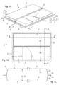
- FIGS. 1A to 1G show a housing arrangement 2 according to the invention, in which electrical storage means 3 can be accommodated, in a first embodiment.
- a housing arrangement 2 can be connected to the body of a motor vehicle.
- the electrical storage means 3 serve to store electrical energy, with which an electric motor of the electrically driven motor vehicle can be supplied with power.
- the housing arrangement 2 has a tray arrangement 4 and a cover arrangement 5, which can be detachably connected to one another, for example by means of screw or Bolt connections (not shown).
- the housing arrangement 2 has a relatively flat structure, although it is understood that other housing shapes are also possible depending on the size, shape and number of electrical storage means 3 to be accommodated.
- the length L2 and/or the width B2 of the housing arrangement 2 can be many times greater than its average height H2, in particular greater than 4 times the average height H2 (L2 > 4H2 and/or B2 > 4H2), possibly also greater than 8 times the average height H2 (L2 > 8H2 and/or B2 > 8H2).
- the tray arrangement 4 can also be referred to as the upper shell and the cover arrangement 5 can also be referred to as the lower shell.
- the trough arrangement 4 comprises a first molded part 6 and a second molded part 7, which are firmly connected or joined to one another, for example by means of welding.
- the two molded parts 6, 7 are designed identically in the present case, although it is understood that they can also be designed differently. As can be seen in particular in the Figures 1C and 1D As can be seen, the two molded parts 6, 7 are trough-shaped and each comprise a base 19 and a circumferential side wall 20, which are formed in one piece.
- the two molded parts 6, 7 are arranged next to one another and connected to one another along their length L4.
- the length L6, L7 of the molded parts 6, 7 in the present embodiment is greater than their respective width B6, B7, without being restricted thereto.
- the housing arrangement 2 can be installed in the motor vehicle such that the longitudinal extension direction x of the housing is aligned parallel to the longitudinal direction of the motor vehicle.
- the first and second molded parts 6, 7 are each made of flexibly rolled steel sheet so that they have a variable sheet thickness D6 over the length of the respective molded part 6, 7.
- a projection of the side surface of the tub part 5 is shown in Figure 1F at the end of the arrows P6 and in Figure 1G shown as a detail.
- the details described for one of the molded parts 6, 7 also apply to the other (7, 6).
- the trough part 6 has thickened end sections 8, 9. Due to the greater sheet thickness D8, D9 in the end sections 8, 9, the trough parts 6, 7 have a high strength here, so that high forces can be absorbed and supported.
- the end sections 8, 9 have a thickness D8, D9 of preferably 1.0 mm to 3.5 mm, and a Length L8, L9 preferably 20 mm to 200 mm.
- the trough parts 6, 7 are designed in such a way that they have a flat surface 14 on which the battery modules 3 rest, i.e. the change in the sheet thickness D is directed outwards.
- the reinforcing sections 11 here have a thickness D11 that is smaller than the thickness D8, D9 of the end sections D8, D9 and greater than the thickness D10 of the thinner sections 10.
- the thinner sections 10 can have a sheet thickness of 0.5 mm to 1.5 mm, for example 1.0 mm.
- the reinforcing sections 11 can, for example, have a thickness D11 of 1.0 mm to 3.5 mm.
- the reinforcement sections 11 are arranged in an adjoining area between two battery modules 3 to be inserted into the tray part 6, 7 adjacent to one another. A stiffening function is thus achieved in these adjoining areas between two battery modules 3, so that the housing arrangement 2 with batteries 3 inserted therein has a high level of rigidity overall.
- the thinner sections 10 are located between each two thickened reinforcement sections 11.
- the two tub parts 6, 7 are welded together along their inner longitudinal edges 16, 17 in a connecting area 15 running in the longitudinal direction x, which can also be referred to as a joining area.
- the longitudinal edges 16, 17 in the connecting area form the side edges of a circumferential flange section 18, 18' of the respective tub part 6, 7.
- the longitudinal edges 16, 17 of the two tub parts 6, 7 are welded together in a butt joint, as shown in Figure 1E shown schematically. It is understood that Other designs of the connection are also possible, which will be explained in more detail below.
- the joining area extends in the longitudinal direction between the two molded parts and thus forms a longitudinal web with a corresponding reinforcement function in the longitudinal direction.
- the cover arrangement 4 is constructed similarly to the tub arrangement 3 and comprises a first molded part 21 and a second molded part 22, which are firmly connected to one another in the connecting area 23.
- the two molded parts 21, 22 are designed the same in the present case, although it is understood that they can also be designed differently. Furthermore, the cover arrangement can also be made from one part. As can be seen in particular in the Figures 1C and 1D As can be seen, the two molded parts 21, 22 are designed in the shape of a trough and comprise a base 24 and a circumferential side wall 25 as well as a circumferential flange section 26, which are formed in one piece. The two molded parts 21, 22 are arranged next to one another and connected to one another over their length L5.
- the two molded parts 21, 22, which can also be referred to as cover parts, are made of sheet steel with a constant sheet thickness D21, D22, without being restricted to this.
- the cover arrangement 5 can also - like the pan arrangement - be made of sheet metal with a variable thickness or of another material, such as light metal or plastic, in particular fiber-reinforced plastic.
- the material thickness of the cover parts 21, 22 is designed as required for the strength or crash properties.
- the tray arrangement 4 and the cover arrangement 5 are firmly connected to one another after the battery modules 3 have been inserted. This can be done, for example, by means of screw connections (not shown) with which the flange sections 18, 26 of the superimposed molded parts 6, 21; 7, 22 are connected to one another. In this case, it is particularly provided that the joint between the tray arrangement 4 and the cover arrangement 5 is sealed to the outside by means of suitable sealing means, for example a circumferential sealing ring or adhesive sealing compound.
- suitable sealing means for example a circumferential sealing ring or adhesive sealing compound.
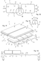
- FIGS. 2A to 2C show a housing arrangement 2 according to the invention in a further embodiment. This largely corresponds to the embodiment according to Figures 1A to 1G , so that with regard to the similarities, reference is made to the above description. The same or corresponding components are provided with the same reference numerals as in Figure 1 .
- a first difference is the design of the connection 15 between the first tub part 6 and the second tub part 7.
- the flange section 18 of the first tub part 6 and the flange section 18' of the second tub part 7 are designed such that they overlap each other in the connecting region 15. In this way, the material thickness is doubled here, so that a higher overall strength and rigidity is achieved in the longitudinal direction of the arrangement 2.
- tub parts 6, 7 each have reinforcement plates 27 welded along their outer side walls 20, which preferably extend over the entire length of the tub sections and thus also ensure increased strength or rigidity.
- FIGS 3A to 3C show a housing arrangement 2 according to the invention in a further embodiment. This largely corresponds to the embodiment according to Figures 1A to 1G , so that with regard to the similarities, reference is made to the above description. The same or corresponding components are provided with the same reference numerals as in Figure 1 .
- the flange section 18 of the first tub part 6 and the flange section 18' of the second tub part 7 are placed against each other with their edges 16, 17 and by means of a reinforcing element 28, also called a patch, connected to one another.
- the connection can be made, for example, by welding in the area of the flanges 18, 19 with the reinforcing element 28. In this way, the material thickness in the connection area 15 is doubled, so that overall a higher strength and rigidity is achieved in the longitudinal direction of the arrangement 2.
- a further special feature of the present embodiment is that both the tub parts 6, 7 - as in the embodiment according to Figure 2 - as well as the cover parts 21, 22 each have reinforcement plates 27, 29 welded along their outer side walls 20, 25, which preferably extend over the entire length of the trough-shaped mold sections and thus also ensure increased strength and rigidity in the longitudinal direction.
- connection arrangement with a butt joint of the tub parts 6, 7 as in Figure 1 shown, with a stiffening of the edge area of the tub and/or the lid as in Figure 2C 3C respectively.
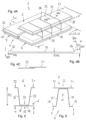
- FIGS. 4A to 4C show a housing arrangement 2 according to the invention in a further embodiment. This largely corresponds to the embodiment according to Figures 1A to 1G , so that with regard to the similarities, reference is made to the above description. The same or corresponding components are provided with the same reference numerals as in Figure 1 .
- the design of the trough arrangement 4 corresponds to the trough arrangement according to Figure 1 , so that in order to avoid repetition, the above description of the Figure 1 reference is made.
- the cover assembly 5 also includes molded parts 21 made of flexible rolled strip material, 22.
- the special feature is that the molded parts 21, 22 have a variable sheet thickness in the transverse direction y of the housing arrangement 2, i.e. perpendicular to the variable thickness profile of the trough arrangement 4.
- the molded parts 21, 22 extend over the entire width B of the housing arrangement 2, i.e. from one outer edge 35 to the other outer edge 36.
- the sheet metal plates from which the molded parts 21, 22 are made are designed identically to one another, but can also have different sheet thicknesses. As long as the two molded parts 21, 22 are designed identically, the details described for one molded part 21 also apply to the other molded part 22.
- Figure 4A It can be seen that the molded part 21 has a variable sheet thickness D21 over the length of the molded part 21.
- a projection of the side surface of the molded part 21, which can also be referred to as the cover part, is shown in Figure 4A at the end of the arrows and in Figure 4B shown as a detail. It can be seen that the cover part 21 has thickened end sections 31, 32.
- the cover parts 21, 22 Due to the greater sheet thickness D31, D32 in the end sections 31, 32, the cover parts 21, 22 have a high level of strength, so that high lateral forces can be absorbed and supported.
- the thickness profile can be individually adjusted according to the requirements in terms of strength and rigidity.
- the end section 31 on the outside has a greater thickness D31 than the inner section 32, which is connected to the adjacent cover part 22.
- the thickness of the end sections 31, 32 can be, for example, between 1.0 mm and 3.5 mm
- the width B31, B32 can be, for example, between 20 mm and 200 mm.
- a thinner section 33 is provided between the end sections 31, 32, which can have a thickness of, for example, 0.5 mm to 1.5 mm. Between the thickened end sections 31, 32 and the thinner section 33, transition sections 34 with continuously varying sheet thickness are formed.
- both the tub part 4 and the cover part 5 are tub-shaped, with a bottom 19 and top 24 respectively and a surrounding wall section 20, 25.
- a modified embodiment which is shown in Figure 5
- the trough arrangement 4 is flat in the connecting area 15 and the trough shape of the cover 5 extends over the entire height H2.
- a reverse embodiment which is shown in FIG. Figure 6
- the cover arrangement 5 is flat in the connecting region 23 and the trough shape of the trough 4 extends over the entire height H2.
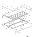
- the Figure 7 shows a housing arrangement 2 according to the invention in a further embodiment. This largely corresponds to the embodiment according to Figures 1A to 1G , or the embodiment according to Figures 4A to 4C , to whose description reference is made with regard to the similarities. Identical or corresponding components are provided with the same reference numerals as in the above figures.
- the cover arrangement 5 is made of several sheet metal plates made of flexibly rolled strip material.
- the end-side molded parts 21, 21' have a first sheet thickness profile, the projection of which can be seen at the end of the arrows P21.
- the molded part 22 lying between the end molded parts 21, 21' has a second sheet thickness profile, the projection of which can be seen at the end of the arrows P22.
- All molded parts 21, 22 of the cover 5 have a variable sheet thickness in the transverse direction y of the housing arrangement 2, i.e. perpendicular to the variable thickness profile of the trough arrangement 4.
- the molded parts 21, 22 each extend over the entire width B2 of the housing arrangement 2, i.e. from one outer edge 35 to the other outer edge 36.
- the sheet metal plates from which the end-side molded parts 21, 21' are made are designed identically to one another in the present case, but can also have different sheet thicknesses.
- the cover part 21 has thickened end sections 31, 32, to which thinner intermediate sections 33 are connected in the direction of the connecting section 23, with a thickening 42, 43 being provided in the central area of each trough-shaped depression. Between the two thickenings 42, 43 there is again a central section 33 with a small sheet thickness D33, which is connected to the connecting section 15 of the trough arrangement 4 in the assembled state.
- the end-side thickenings 31, 32 provide increased strength against lateral impact forces.
- the central thickenings 42, 43 increase the load-bearing capacity in the longitudinal direction x of the housing arrangement 2.
- the thickness of the sheet metal plate from which the middle cover part 22 is made is similar to that in the embodiment according to Figure 4
- the end sections 31, 32 are thickened, whereby the thickness can be set in particular as in the case of the end sections of the end plates 21, 21'.
- An intermediate section 33 with a constant, smaller sheet thickness D33 is provided between the end sections 31, 32.
- the width B22 of the central plate 22 is greater than the width B21, B21' of the end plates 21, 21'.
- the adjacent plates 21, 22; 22, 21' can be connected to one another in a butt joint or overlapping manner.
- One or more of the molded parts 21, 22, 21' can be provided with stiffening beads 44, 45, 44'.
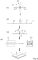
- FIG 8 an example of a method according to the invention for producing a tray or cover section 4, 5 for a housing arrangement 2 according to the invention is shown in a possible embodiment.
- the strip material 50 which is wound on a coil 51 in the initial state, is rolled using flexible rolling.
- the strip material 50 which has a largely constant sheet thickness along its length before flexible rolling, is rolled using rollers 52 in such a way that it has a variable sheet thickness along the rolling direction.
- the process is monitored and controlled, with the data determined by a sheet thickness measurement being used as an input signal for controlling the rollers 52.
- the strip material 50 has regions of different thicknesses that extend transversely to the rolling direction.
- the strip material is wound back into a coil so that it can be fed to the next process step.
- process step V2 the flexibly rolled steel strip is separated into sheet metal blanks 53, 53'.
- two sheet metal plates 53, 53' are connected to one another, in particular welded, to form a plate assembly 54.
- the connection is made along the longest length of the sheet metal plates 53, 53 ⁇ , i.e. transversely to the individual thick and thin sections of the plates.
- the blank assembly 54 is formed by means of hot forming.
- the hot forming comprises the sub-steps of heating in a furnace 56, transfer into the hot forming tool 57, where the blank assembly 54 is formed into a tub arrangement 4 or cover arrangement 5 and hardened.
Landscapes
- Chemical & Material Sciences (AREA)
- Chemical Kinetics & Catalysis (AREA)
- Electrochemistry (AREA)
- General Chemical & Material Sciences (AREA)
- Engineering & Computer Science (AREA)
- Inorganic Chemistry (AREA)
- Mechanical Engineering (AREA)
- Transportation (AREA)
- Sustainable Energy (AREA)
- Power Engineering (AREA)
- Sustainable Development (AREA)
- Life Sciences & Earth Sciences (AREA)
- Combustion & Propulsion (AREA)
- Battery Mounting, Suspending (AREA)
- Pallets (AREA)
- Casings For Electric Apparatus (AREA)
Applications Claiming Priority (1)
| Application Number | Priority Date | Filing Date | Title |
|---|---|---|---|
| DE102018106399.7A DE102018106399A1 (de) | 2018-03-19 | 2018-03-19 | Gehäuseanordnung zur Aufnahme elektrischer Speichermittel und Verfahren zur Herstellung einer Gehäuseanordnung |
Publications (4)
| Publication Number | Publication Date |
|---|---|
| EP3544082A1 EP3544082A1 (de) | 2019-09-25 |
| EP3544082B1 EP3544082B1 (de) | 2024-07-03 |
| EP3544082C0 EP3544082C0 (de) | 2024-07-03 |
| EP3544082B9 true EP3544082B9 (de) | 2024-12-11 |
Family
ID=65729102
Family Applications (1)
| Application Number | Title | Priority Date | Filing Date |
|---|---|---|---|
| EP19160921.3A Active EP3544082B9 (de) | 2018-03-19 | 2019-03-05 | Gehäuseanordnung zur aufnahme elektrischer speichermittel und verfahren zur herstellung einer gehäuseanordnung |
Country Status (7)
| Country | Link |
|---|---|
| US (1) | US11091014B2 (pl) |
| EP (1) | EP3544082B9 (pl) |
| CN (1) | CN110289375B (pl) |
| DE (1) | DE102018106399A1 (pl) |
| ES (1) | ES2992826T3 (pl) |
| HU (1) | HUE069043T2 (pl) |
| PL (1) | PL3544082T3 (pl) |
Families Citing this family (10)
| Publication number | Priority date | Publication date | Assignee | Title |
|---|---|---|---|---|
| DE102018132171A1 (de) * | 2018-12-13 | 2020-06-18 | Thyssenkrupp Steel Europe Ag | Batteriegehäuse und Verwendung |
| DE102019210400A1 (de) * | 2019-07-15 | 2021-01-21 | Muhr Und Bender Kg | Gehäuseanordnung zur Aufnahme elektrischer Speichermittel |
| DE102019210398A1 (de) * | 2019-07-15 | 2021-01-21 | Muhr Und Bender Kg | Gehäuseanordnung zur Aufnahme elektrischer Speichermittel |
| CN112701408B (zh) * | 2020-12-25 | 2022-12-09 | 孚能科技(赣州)股份有限公司 | 箱体底盘的底板结构、箱体底盘、电池包和汽车 |
| DE102021122913A1 (de) | 2021-09-03 | 2023-03-09 | Muhr Und Bender Kg | Batteriekühlvorrichtung für ein elektrisches Batteriemodul eines Elektroantriebs |
| DE102021122902A1 (de) | 2021-09-03 | 2023-03-09 | Muhr Und Bender Kg | Gehäuseanordnung |
| DE102021132283A1 (de) * | 2021-12-08 | 2023-06-15 | Bayerische Motoren Werke Aktiengesellschaft | Energiespeichergehäuse, Kraftfahrzeug, elektrischer Energiespeicher sowie Baureihe |
| EP4318760A1 (de) * | 2022-08-03 | 2024-02-07 | Benteler Automobiltechnik GmbH | Verfahren zur herstellung einer batteriewanne für ein kraftfahrzeug |
| DE102022127777A1 (de) * | 2022-10-20 | 2024-04-25 | Friedrich Boysen GmbH & Co KG. | Batteriegehäuse |
| WO2025214575A1 (de) * | 2024-04-08 | 2025-10-16 | Benteler Automobiltechnik Gmbh | Batterieeinhausung |
Family Cites Families (41)
| Publication number | Priority date | Publication date | Assignee | Title |
|---|---|---|---|---|
| US5501289A (en) * | 1993-01-22 | 1996-03-26 | Nissan Motor Co., Ltd. | Floor structure of electric vehicle |
| DE10246164B4 (de) * | 2002-10-02 | 2014-03-20 | Benteler Automobiltechnik Gmbh | Verfahren zum Herstellen von Strukturbauteilen |
| JP5151363B2 (ja) * | 2007-09-28 | 2013-02-27 | 三菱自動車工業株式会社 | 電気自動車用バッテリケース |
| US8110300B2 (en) * | 2008-06-30 | 2012-02-07 | Lg Chem, Ltd. | Battery mounting system |
| JP5408440B2 (ja) * | 2010-01-18 | 2014-02-05 | 三菱自動車工業株式会社 | 車両用バッテリケース |
| KR20120044853A (ko) * | 2010-10-28 | 2012-05-08 | 현대자동차주식회사 | 플라스틱 복합재를 이용한 전기자동차용 배터리팩 케이스 어셈블리 |
| JP5360041B2 (ja) * | 2010-12-15 | 2013-12-04 | 三菱自動車工業株式会社 | バッテリケース |
| DE102011051698A1 (de) * | 2011-07-08 | 2013-01-10 | Thyssenkrupp Steel Europe Ag | Bodenstruktur für ein Fahrzeug |
| JP5364767B2 (ja) * | 2011-09-26 | 2013-12-11 | 富士重工業株式会社 | 車両用バッテリ支持構造 |
| JP5734453B2 (ja) * | 2011-11-14 | 2015-06-17 | 本田技研工業株式会社 | バッテリの車載構造 |
| JP5692019B2 (ja) * | 2011-11-22 | 2015-04-01 | トヨタ自動車株式会社 | サービスホールカバー取付構造、及びこれを備えた車両用電池搭載構造 |
| KR101315741B1 (ko) * | 2012-03-23 | 2013-10-10 | 현대자동차주식회사 | 치수안정성이 우수한 전기자동차용 배터리 팩 케이스 어셈블리와 그 제조 방법 |
| WO2014061109A1 (ja) * | 2012-10-16 | 2014-04-24 | トヨタ自動車株式会社 | 車両用電池搭載構造 |
| DE102013215436A1 (de) * | 2013-08-06 | 2015-03-05 | Bayerische Motoren Werke Aktiengesellschaft | Vorrichtung zur Aufnahme zumindest eines Energiemoduls für ein Kraftfahrzeug |
| DE102013224924B4 (de) * | 2013-12-04 | 2022-05-05 | Muhr Und Bender Kg | Container und Verfahren zur Herstellung eines Containers |
| JP6304587B2 (ja) * | 2014-03-06 | 2018-04-04 | 三菱自動車工業株式会社 | 電動車両用の電池パック |
| WO2015151866A1 (ja) * | 2014-03-31 | 2015-10-08 | 日本電気株式会社 | 蓄電池装置 |
| DE102014216225A1 (de) * | 2014-08-14 | 2016-02-18 | Muhr Und Bender Kg | Strukturbauteil und Verfahren zur Herstellung eines Strukturbauteils |
| DE102014226566B3 (de) | 2014-12-19 | 2016-04-28 | Volkswagen Aktiengesellschaft | Batteriekasten für eine Traktionsbatterie in Kraftfahrzeugen |
| JP6615196B2 (ja) * | 2015-06-04 | 2019-12-04 | 本田技研工業株式会社 | 車両用バッテリユニット |
| JP6118381B2 (ja) * | 2015-09-30 | 2017-04-19 | 富士重工業株式会社 | 車載用バッテリー |
| PL3181248T3 (pl) * | 2015-12-18 | 2018-06-29 | Muhr Und Bender Kg | Sposób i układ do wytwarzania arkusza blaszanego |
| US10017037B2 (en) * | 2016-02-09 | 2018-07-10 | Nio Usa, Inc. | Vehicle having a battery pack directly attached to the cross rails of a frame structure |
| JP6520808B2 (ja) * | 2016-04-21 | 2019-05-29 | トヨタ自動車株式会社 | 車両のバッテリ搭載構造 |
| DE102016108849B3 (de) * | 2016-05-12 | 2017-04-20 | Benteler Automobiltechnik Gmbh | Batteriehalter für ein Kraftfahrzeug |
| US10381621B2 (en) * | 2016-11-01 | 2019-08-13 | Ford Global Technologies, Llc | Traction battery energy absorbing method and assembly |
| US10431791B2 (en) * | 2016-11-01 | 2019-10-01 | Ford Global Technologies, Llc | Traction battery pack shield and shielding method |
| DE102016120826B4 (de) * | 2016-11-02 | 2018-08-23 | Kirchhoff Automotive Deutschland Gmbh | Batteriegehäuse |
| JP6555244B2 (ja) * | 2016-12-19 | 2019-08-07 | トヨタ自動車株式会社 | 車両 |
| DE102017102699B4 (de) * | 2017-02-10 | 2021-01-28 | Benteler Automobiltechnik Gmbh | Batterieträger mit verbesserten Crasheigenschaften |
| JP6523355B2 (ja) * | 2017-02-17 | 2019-05-29 | 本田技研工業株式会社 | 車体の下部構造 |
| JP6514248B2 (ja) * | 2017-02-17 | 2019-05-15 | 本田技研工業株式会社 | 車体の下部構造 |
| JP7020804B2 (ja) * | 2017-06-19 | 2022-02-16 | 本田技研工業株式会社 | バッテリパック |
| JP7095307B2 (ja) * | 2018-02-23 | 2022-07-05 | トヨタ自動車株式会社 | 車両下部構造 |
| JP7067142B2 (ja) * | 2018-03-09 | 2022-05-16 | トヨタ自動車株式会社 | 車両下部構造 |
| JP7110648B2 (ja) * | 2018-03-22 | 2022-08-02 | トヨタ自動車株式会社 | 車両 |
| JP7059737B2 (ja) * | 2018-03-22 | 2022-04-26 | トヨタ自動車株式会社 | 電池パック |
| KR102575355B1 (ko) * | 2018-04-26 | 2023-09-07 | 현대자동차주식회사 | 차량용 배터리 케이스 |
| US10559793B2 (en) * | 2018-05-17 | 2020-02-11 | Ford Global Technologies, Llc | Battery array retention method and assembly |
| JP7168346B2 (ja) * | 2018-05-25 | 2022-11-09 | 矢崎総業株式会社 | バッテリモジュール |
| US10822039B2 (en) * | 2019-02-18 | 2020-11-03 | GM Global Technology Operations LLC | Body rocker, battery cross-bar, and body cross-bar configuration for load distribution between vehicle body and under-vehicle battery |
-
2018
- 2018-03-19 DE DE102018106399.7A patent/DE102018106399A1/de active Pending
-
2019
- 2019-03-05 PL PL19160921.3T patent/PL3544082T3/pl unknown
- 2019-03-05 HU HUE19160921A patent/HUE069043T2/hu unknown
- 2019-03-05 EP EP19160921.3A patent/EP3544082B9/de active Active
- 2019-03-05 ES ES19160921T patent/ES2992826T3/es active Active
- 2019-03-07 US US16/295,119 patent/US11091014B2/en active Active
- 2019-03-18 CN CN201910211018.9A patent/CN110289375B/zh not_active Expired - Fee Related
Also Published As
| Publication number | Publication date |
|---|---|
| PL3544082T3 (pl) | 2024-11-25 |
| EP3544082B1 (de) | 2024-07-03 |
| HUE069043T2 (hu) | 2025-02-28 |
| CN110289375A (zh) | 2019-09-27 |
| CN110289375B (zh) | 2023-07-25 |
| US20190283562A1 (en) | 2019-09-19 |
| EP3544082C0 (de) | 2024-07-03 |
| US11091014B2 (en) | 2021-08-17 |
| EP3544082A1 (de) | 2019-09-25 |
| ES2992826T3 (en) | 2024-12-18 |
| DE102018106399A1 (de) | 2019-09-19 |
Similar Documents
| Publication | Publication Date | Title |
|---|---|---|
| EP3544082B9 (de) | Gehäuseanordnung zur aufnahme elektrischer speichermittel und verfahren zur herstellung einer gehäuseanordnung | |
| WO2018158363A1 (de) | Batteriegehäuse | |
| DE102019210400A1 (de) | Gehäuseanordnung zur Aufnahme elektrischer Speichermittel | |
| DE69817149T2 (de) | Ladeplattform eines fahrzeuges | |
| EP3465795A1 (de) | Gehäuse für eine fahrzeugbatterie sowie verfahren zur herstellung eines solchen gehäuses | |
| DE102018120268A1 (de) | Batteriekasten mit Verstärkungselement | |
| WO2018166895A1 (de) | Batterieaufnahme mit verstärkungsstruktur und verwendung | |
| DE102017126949A1 (de) | Batterieeinrichtung für ein wenigstens teilweise elektrisch betriebenes Kraftfahrzeug | |
| EP2881339B1 (de) | Container und Verfahren zur Herstellung eines Containers | |
| DE102022122358A1 (de) | Tragende baugruppe mit gemusterten tafeln | |
| DE202016104744U1 (de) | Bodengruppe für eine Batteriemodulaufnahme | |
| DE102022108960A1 (de) | Blechbaugruppe mit verstärkungselementen mit vorgegebener ziehtiefe | |
| EP4396894B1 (de) | Gehäuseanordnung | |
| DE102022109383A1 (de) | Strukturanordnung mit gemusterten platten | |
| DE102013011951A1 (de) | Verfahren zum Fertigen von Kraftfahrzeug-Karosserieteilen | |
| DE102006055657A1 (de) | Bauteil aus einem Flachmaterial und Verfahren zu seiner Herstellung | |
| DE102021122913A1 (de) | Batteriekühlvorrichtung für ein elektrisches Batteriemodul eines Elektroantriebs | |
| EP3999260A1 (de) | Gehäuseanordnung zur aufnahme elektrischer speichermittel | |
| EP3909864B1 (de) | Verfahren zur fertigung eines strukturbauteils für ein fahrzeug, insbesondere ein luft- oder raumfahrzeug | |
| DE102016008830A1 (de) | Verbund-Metallteil und Herstellungsverfahren dafür | |
| EP4167329B1 (de) | Batterieträger für ein elektrisch angetriebenes fahrzeug und verfahren zum herstellen eines solchen batterieträgers | |
| EP4663446A1 (de) | Batterieträger für ein elektrofahrzeug | |
| EP4126410B1 (de) | Abstandsstruktur, sandwich-konstruktion mit einer solchen abstandsstruktur und verfahren zur herstellung einer solchen abstandsstruktur | |
| DE102018219197A1 (de) | Batteriegehäuse für ein Fahrzeug und Verfahren zu seiner Herstellung | |
| EP3501952B1 (de) | Toleranzausgleich bei montageteilen in baugruppen durch elastische elemente |
Legal Events
| Date | Code | Title | Description |
|---|---|---|---|
| PUAI | Public reference made under article 153(3) epc to a published international application that has entered the european phase |
Free format text: ORIGINAL CODE: 0009012 |
|
| STAA | Information on the status of an ep patent application or granted ep patent |
Free format text: STATUS: THE APPLICATION HAS BEEN PUBLISHED |
|
| AK | Designated contracting states |
Kind code of ref document: A1 Designated state(s): AL AT BE BG CH CY CZ DE DK EE ES FI FR GB GR HR HU IE IS IT LI LT LU LV MC MK MT NL NO PL PT RO RS SE SI SK SM TR |
|
| AX | Request for extension of the european patent |
Extension state: BA ME |
|
| STAA | Information on the status of an ep patent application or granted ep patent |
Free format text: STATUS: REQUEST FOR EXAMINATION WAS MADE |
|
| 17P | Request for examination filed |
Effective date: 20200306 |
|
| RBV | Designated contracting states (corrected) |
Designated state(s): AL AT BE BG CH CY CZ DE DK EE ES FI FR GB GR HR HU IE IS IT LI LT LU LV MC MK MT NL NO PL PT RO RS SE SI SK SM TR |
|
| STAA | Information on the status of an ep patent application or granted ep patent |
Free format text: STATUS: EXAMINATION IS IN PROGRESS |
|
| 17Q | First examination report despatched |
Effective date: 20200915 |
|
| REG | Reference to a national code |
Ref country code: DE Ref legal event code: R079 Free format text: PREVIOUS MAIN CLASS: H01M0002100000 Ipc: H01M0050240000 Ref country code: DE Ref legal event code: R079 Ref document number: 502019011541 Country of ref document: DE Free format text: PREVIOUS MAIN CLASS: H01M0002100000 Ipc: H01M0050240000 |
|
| GRAP | Despatch of communication of intention to grant a patent |
Free format text: ORIGINAL CODE: EPIDOSNIGR1 |
|
| STAA | Information on the status of an ep patent application or granted ep patent |
Free format text: STATUS: GRANT OF PATENT IS INTENDED |
|
| RIC1 | Information provided on ipc code assigned before grant |
Ipc: H01M 50/271 20210101ALI20240116BHEP Ipc: H01M 50/224 20210101ALI20240116BHEP Ipc: H01M 50/24 20210101AFI20240116BHEP |
|
| INTG | Intention to grant announced |
Effective date: 20240212 |
|
| GRAS | Grant fee paid |
Free format text: ORIGINAL CODE: EPIDOSNIGR3 |
|
| GRAA | (expected) grant |
Free format text: ORIGINAL CODE: 0009210 |
|
| STAA | Information on the status of an ep patent application or granted ep patent |
Free format text: STATUS: THE PATENT HAS BEEN GRANTED |
|
| AK | Designated contracting states |
Kind code of ref document: B1 Designated state(s): AL AT BE BG CH CY CZ DE DK EE ES FI FR GB GR HR HU IE IS IT LI LT LU LV MC MK MT NL NO PL PT RO RS SE SI SK SM TR |
|
| REG | Reference to a national code |
Ref country code: CH Ref legal event code: EP |
|
| REG | Reference to a national code |
Ref country code: DE Ref legal event code: R096 Ref document number: 502019011541 Country of ref document: DE |
|
| U01 | Request for unitary effect filed |
Effective date: 20240724 |
|
| U07 | Unitary effect registered |
Designated state(s): AT BE BG DE DK EE FI FR IT LT LU LV MT NL PT SE SI Effective date: 20240809 |
|
| REG | Reference to a national code |
Ref country code: SK Ref legal event code: T3 Ref document number: E 44894 Country of ref document: SK |
|
| REG | Reference to a national code |
Ref country code: CH Ref legal event code: PK Free format text: BERICHTIGUNG B9 |
|
| REG | Reference to a national code |
Ref country code: ES Ref legal event code: FG2A Ref document number: 2992826 Country of ref document: ES Kind code of ref document: T3 Effective date: 20241218 |
|
| PG25 | Lapsed in a contracting state [announced via postgrant information from national office to epo] |
Ref country code: NO Free format text: LAPSE BECAUSE OF FAILURE TO SUBMIT A TRANSLATION OF THE DESCRIPTION OR TO PAY THE FEE WITHIN THE PRESCRIBED TIME-LIMIT Effective date: 20241003 |
|
| PG25 | Lapsed in a contracting state [announced via postgrant information from national office to epo] |
Ref country code: GR Free format text: LAPSE BECAUSE OF FAILURE TO SUBMIT A TRANSLATION OF THE DESCRIPTION OR TO PAY THE FEE WITHIN THE PRESCRIBED TIME-LIMIT Effective date: 20241004 |
|
| PG25 | Lapsed in a contracting state [announced via postgrant information from national office to epo] |
Ref country code: IS Free format text: LAPSE BECAUSE OF FAILURE TO SUBMIT A TRANSLATION OF THE DESCRIPTION OR TO PAY THE FEE WITHIN THE PRESCRIBED TIME-LIMIT Effective date: 20241103 |
|
| PG25 | Lapsed in a contracting state [announced via postgrant information from national office to epo] |
Ref country code: HR Free format text: LAPSE BECAUSE OF FAILURE TO SUBMIT A TRANSLATION OF THE DESCRIPTION OR TO PAY THE FEE WITHIN THE PRESCRIBED TIME-LIMIT Effective date: 20240703 |
|
| PG25 | Lapsed in a contracting state [announced via postgrant information from national office to epo] |
Ref country code: RS Free format text: LAPSE BECAUSE OF FAILURE TO SUBMIT A TRANSLATION OF THE DESCRIPTION OR TO PAY THE FEE WITHIN THE PRESCRIBED TIME-LIMIT Effective date: 20241003 |
|
| PG25 | Lapsed in a contracting state [announced via postgrant information from national office to epo] |
Ref country code: RS Free format text: LAPSE BECAUSE OF FAILURE TO SUBMIT A TRANSLATION OF THE DESCRIPTION OR TO PAY THE FEE WITHIN THE PRESCRIBED TIME-LIMIT Effective date: 20241003 Ref country code: NO Free format text: LAPSE BECAUSE OF FAILURE TO SUBMIT A TRANSLATION OF THE DESCRIPTION OR TO PAY THE FEE WITHIN THE PRESCRIBED TIME-LIMIT Effective date: 20241003 Ref country code: IS Free format text: LAPSE BECAUSE OF FAILURE TO SUBMIT A TRANSLATION OF THE DESCRIPTION OR TO PAY THE FEE WITHIN THE PRESCRIBED TIME-LIMIT Effective date: 20241103 Ref country code: HR Free format text: LAPSE BECAUSE OF FAILURE TO SUBMIT A TRANSLATION OF THE DESCRIPTION OR TO PAY THE FEE WITHIN THE PRESCRIBED TIME-LIMIT Effective date: 20240703 Ref country code: GR Free format text: LAPSE BECAUSE OF FAILURE TO SUBMIT A TRANSLATION OF THE DESCRIPTION OR TO PAY THE FEE WITHIN THE PRESCRIBED TIME-LIMIT Effective date: 20241004 |
|
| REG | Reference to a national code |
Ref country code: SK Ref legal event code: T4 Ref document number: E 44894 Country of ref document: SK |
|
| REG | Reference to a national code |
Ref country code: HU Ref legal event code: AG4A Ref document number: E069043 Country of ref document: HU |
|
| PG25 | Lapsed in a contracting state [announced via postgrant information from national office to epo] |
Ref country code: SM Free format text: LAPSE BECAUSE OF FAILURE TO SUBMIT A TRANSLATION OF THE DESCRIPTION OR TO PAY THE FEE WITHIN THE PRESCRIBED TIME-LIMIT Effective date: 20240703 |
|
| U20 | Renewal fee for the european patent with unitary effect paid |
Year of fee payment: 7 Effective date: 20250307 |
|
| PGFP | Annual fee paid to national office [announced via postgrant information from national office to epo] |
Ref country code: HU Payment date: 20250214 Year of fee payment: 7 |
|
| PGFP | Annual fee paid to national office [announced via postgrant information from national office to epo] |
Ref country code: CZ Payment date: 20250214 Year of fee payment: 7 Ref country code: PL Payment date: 20250227 Year of fee payment: 7 |
|
| PGFP | Annual fee paid to national office [announced via postgrant information from national office to epo] |
Ref country code: SK Payment date: 20250214 Year of fee payment: 7 Ref country code: GB Payment date: 20250324 Year of fee payment: 7 |
|
| PLBE | No opposition filed within time limit |
Free format text: ORIGINAL CODE: 0009261 |
|
| STAA | Information on the status of an ep patent application or granted ep patent |
Free format text: STATUS: NO OPPOSITION FILED WITHIN TIME LIMIT |
|
| 26N | No opposition filed |
Effective date: 20250404 |
|
| PGFP | Annual fee paid to national office [announced via postgrant information from national office to epo] |
Ref country code: ES Payment date: 20250404 Year of fee payment: 7 |
|
| PGFP | Annual fee paid to national office [announced via postgrant information from national office to epo] |
Ref country code: CH Payment date: 20250401 Year of fee payment: 7 |
|
| PG25 | Lapsed in a contracting state [announced via postgrant information from national office to epo] |
Ref country code: MC Free format text: LAPSE BECAUSE OF FAILURE TO SUBMIT A TRANSLATION OF THE DESCRIPTION OR TO PAY THE FEE WITHIN THE PRESCRIBED TIME-LIMIT Effective date: 20240703 |