EP3543688A1 - Inspection method - Google Patents
Inspection method Download PDFInfo
- Publication number
- EP3543688A1 EP3543688A1 EP17892411.4A EP17892411A EP3543688A1 EP 3543688 A1 EP3543688 A1 EP 3543688A1 EP 17892411 A EP17892411 A EP 17892411A EP 3543688 A1 EP3543688 A1 EP 3543688A1
- Authority
- EP
- European Patent Office
- Prior art keywords
- wedge
- test object
- ultrasound
- transmitter
- surface waves
- Prior art date
- Legal status (The legal status is an assumption and is not a legal conclusion. Google has not performed a legal analysis and makes no representation as to the accuracy of the status listed.)
- Withdrawn
Links
Images




Classifications
-
- G—PHYSICS
- G01—MEASURING; TESTING
- G01N—INVESTIGATING OR ANALYSING MATERIALS BY DETERMINING THEIR CHEMICAL OR PHYSICAL PROPERTIES
- G01N29/00—Investigating or analysing materials by the use of ultrasonic, sonic or infrasonic waves; Visualisation of the interior of objects by transmitting ultrasonic or sonic waves through the object
- G01N29/04—Analysing solids
- G01N29/07—Analysing solids by measuring propagation velocity or propagation time of acoustic waves
-
- G—PHYSICS
- G01—MEASURING; TESTING
- G01N—INVESTIGATING OR ANALYSING MATERIALS BY DETERMINING THEIR CHEMICAL OR PHYSICAL PROPERTIES
- G01N29/00—Investigating or analysing materials by the use of ultrasonic, sonic or infrasonic waves; Visualisation of the interior of objects by transmitting ultrasonic or sonic waves through the object
- G01N29/04—Analysing solids
- G01N29/041—Analysing solids on the surface of the material, e.g. using Lamb, Rayleigh or shear waves
-
- G—PHYSICS
- G01—MEASURING; TESTING
- G01N—INVESTIGATING OR ANALYSING MATERIALS BY DETERMINING THEIR CHEMICAL OR PHYSICAL PROPERTIES
- G01N29/00—Investigating or analysing materials by the use of ultrasonic, sonic or infrasonic waves; Visualisation of the interior of objects by transmitting ultrasonic or sonic waves through the object
- G01N29/22—Details, e.g. general constructional or apparatus details
- G01N29/221—Arrangements for directing or focusing the acoustical waves
-
- G—PHYSICS
- G01—MEASURING; TESTING
- G01N—INVESTIGATING OR ANALYSING MATERIALS BY DETERMINING THEIR CHEMICAL OR PHYSICAL PROPERTIES
- G01N29/00—Investigating or analysing materials by the use of ultrasonic, sonic or infrasonic waves; Visualisation of the interior of objects by transmitting ultrasonic or sonic waves through the object
- G01N29/22—Details, e.g. general constructional or apparatus details
- G01N29/223—Supports, positioning or alignment in fixed situation
-
- G—PHYSICS
- G01—MEASURING; TESTING
- G01N—INVESTIGATING OR ANALYSING MATERIALS BY DETERMINING THEIR CHEMICAL OR PHYSICAL PROPERTIES
- G01N29/00—Investigating or analysing materials by the use of ultrasonic, sonic or infrasonic waves; Visualisation of the interior of objects by transmitting ultrasonic or sonic waves through the object
- G01N29/22—Details, e.g. general constructional or apparatus details
- G01N29/28—Details, e.g. general constructional or apparatus details providing acoustic coupling, e.g. water
-
- G—PHYSICS
- G01—MEASURING; TESTING
- G01N—INVESTIGATING OR ANALYSING MATERIALS BY DETERMINING THEIR CHEMICAL OR PHYSICAL PROPERTIES
- G01N2291/00—Indexing codes associated with group G01N29/00
- G01N2291/01—Indexing codes associated with the measuring variable
- G01N2291/011—Velocity or travel time
-
- G—PHYSICS
- G01—MEASURING; TESTING
- G01N—INVESTIGATING OR ANALYSING MATERIALS BY DETERMINING THEIR CHEMICAL OR PHYSICAL PROPERTIES
- G01N2291/00—Indexing codes associated with group G01N29/00
- G01N2291/02—Indexing codes associated with the analysed material
- G01N2291/023—Solids
- G01N2291/0234—Metals, e.g. steel
-
- G—PHYSICS
- G01—MEASURING; TESTING
- G01N—INVESTIGATING OR ANALYSING MATERIALS BY DETERMINING THEIR CHEMICAL OR PHYSICAL PROPERTIES
- G01N2291/00—Indexing codes associated with group G01N29/00
- G01N2291/04—Wave modes and trajectories
- G01N2291/042—Wave modes
- G01N2291/0423—Surface waves, e.g. Rayleigh waves, Love waves
-
- G—PHYSICS
- G01—MEASURING; TESTING
- G01N—INVESTIGATING OR ANALYSING MATERIALS BY DETERMINING THEIR CHEMICAL OR PHYSICAL PROPERTIES
- G01N2291/00—Indexing codes associated with group G01N29/00
- G01N2291/04—Wave modes and trajectories
- G01N2291/044—Internal reflections (echoes), e.g. on walls or defects
-
- G—PHYSICS
- G01—MEASURING; TESTING
- G01N—INVESTIGATING OR ANALYSING MATERIALS BY DETERMINING THEIR CHEMICAL OR PHYSICAL PROPERTIES
- G01N2291/00—Indexing codes associated with group G01N29/00
- G01N2291/04—Wave modes and trajectories
- G01N2291/045—External reflections, e.g. on reflectors
-
- G—PHYSICS
- G01—MEASURING; TESTING
- G01N—INVESTIGATING OR ANALYSING MATERIALS BY DETERMINING THEIR CHEMICAL OR PHYSICAL PROPERTIES
- G01N2291/00—Indexing codes associated with group G01N29/00
- G01N2291/04—Wave modes and trajectories
- G01N2291/057—Angular incidence, parallel to surface propagation
-
- G—PHYSICS
- G01—MEASURING; TESTING
- G01N—INVESTIGATING OR ANALYSING MATERIALS BY DETERMINING THEIR CHEMICAL OR PHYSICAL PROPERTIES
- G01N2291/00—Indexing codes associated with group G01N29/00
- G01N2291/10—Number of transducers
- G01N2291/101—Number of transducers one transducer
Definitions
- the present invention relates to a method for inspecting a test object for defects using an ultrasonic probe.
- Patent Literature 1 discloses a method for inspecting a test object for defects present in a surface area (including the surface and near-surface) of the test object using an ultrasonic probe that includes a transducer having a transmitter and a receiver of ultrasound and a wedge holding the transducer. Specifically, the wedge holds the transmitter at an angle allowing the ultrasound transmitted from the transmitter to propagate as surface waves along the surface area of the test object.
- the receiver receives an ultrasonic echo produced by the reflection of the surface waves by a defect present in the surface area of the test object, thereby allowing detection of the defect.
- the surface area refers to an area with a depth equal to about once or twice the wavelength of the surface waves from the surface of the test object.
- the surface waves may also be reflected by a couplant, such as oil, or a foreign matter adhered to the part of the surface of a test object that lies in front of the wedge in the propagation direction of the surface waves.
- the produced ultrasonic echo will be received by the receiver as a signal.
- it is difficult to determine whether an ultrasonic echo received by the receiver is based on a defect or any foreign matter on the surface which can lead to an increase in false detections of defects.
- such a conventional inspection method requires cleaning of the surface of the inspection zone during the inspection. This makes the supply of couplant troublesome and thus makes it difficult to obtain a reliable defect detection accuracy.
- Patent Literature 1 Japanese Unexamined Patent Publication No. 2010-54497
- An inspection method is a method for inspecting a test object for defects using an ultrasonic probe that includes a transmitter for transmitting ultrasound, a wedge holding the transmitter at an angle allowing the ultrasound transmitted from the transmitter to propagate as surface waves along a surface area of the test object, and a receiver for receiving an ultrasonic echo produced by reflection of the ultrasound, the method comprising the steps of: placing the ultrasonic probe on the test object; transmitting the ultrasound from the transmitter into the wedge such that the surface waves propagate along the surface area of the test object; and determining that there is a defect in a part of the test object overlapped with the wedge when the receiver receives the ultrasonic echo, after the transmission of the ultrasound by the transmitter, in a time shorter than a time required to receive a front end-reflected ultrasonic echo produced by reflection of the surface waves at a front end of the wedge in a propagation direction of the surface waves.
- the present inspection method uses surface waves S to detect a defect present on the surface and near-surface (hereinafter, referred to as "surface area") of a test object T, such as a steel material.
- the surface area refers to an area with a depth equal to about once or twice the wavelength of the surface waves S from the surface of the test object T.
- the inspection method uses an ultrasonic probe 1 that includes a transducer 10, a wedge 20, and a casing 30 housing the transducer 10 and the wedge 20, as shown in Fig. 1 .
- the transducer 10 includes a transmitter for transmitting ultrasound and a receiver for receiving an ultrasonic echo produced by reflection of the ultrasound.
- the wedge 20 holds the transducer 10 at an angle allowing the ultrasound transmitted from the transmitter to propagate as surface waves S (in the form of Rayleigh waves or SH waves) along the surface area of the test object T.
- the wedge 20 is preferably made of polyetherimide or acrylic resin, and more preferably made of polyetherimide.
- the present inspection method includes a placement step, an ultrasound transmission step, and a determination step.
- the ultrasonic probe 1 is placed on the test object T.
- the gap between the contact surfaces of the test object T and the ultrasonic probe 1 is filled with a couplant, such as oil, where the ultrasonic probe 1 is pressed against the test object T such that the couplant forms a uniform thin film between the bottom surface of the ultrasonic probe 1 and the test object T.
- the transmitter of the transducer 10 transmits ultrasound (shown by the dotted arrow in Fig. 1 ).
- Part of the ultrasound travels straight through the wedge 20 and reaches an incident point P (i.e. the point of incidence at which the part of the ultrasound emitted from the center of the transducer 10 enters the surface of the test object T).
- the part of the ultrasound propagates as surface waves S from the incident point P along the surface area of the test object T.
- the couplant is between the ultrasonic probe 1 and the test object T, it is in the form of a uniform thin film between the ultrasonic probe 1 and the test object T.
- the couplant reflects almost no ultrasound.
- the determination step it is determined whether there is a defect f in the part of the test object T overlapped with the wedge 20 (directly under the wedge 20). Specifically, at the determination step, it is determined that there is a defect f in the part of the test object T overlapped with the wedge 20 when the receiver receives an ultrasonic echo W1, after the transmission of ultrasound by the transmitter, in a time shorter than the time required to receive a front end-reflected ultrasonic echo W2 (an ultrasonic echo produced by reflection of the surface waves S at a front end 22 of the wedge 20 in the propagation direction of the surface waves S). The reason why this determination is possible will be described with reference to Fig. 2 .
- Fig. 2 illustrates a reception signal A1 that is detected when the receiver receives the ultrasonic echo W1 produced by the reflection of the surface waves S by the defect f and a reception signal A2 that is detected when the receiver receives the front end-reflected ultrasonic echo W2.
- the reception signal A1 is detected earlier than the reception signal A2 by the receiver.
- the time required to detect the reception signal A2 is measured in advance. This makes it possible to determine, when the receiver receives the reception signal A1 in a time shorter than the detection time for the reception signal A2 (i.e. the signal based on the front end-reflected ultrasonic echo W2), that the reception signal A1 is a signal based on the ultrasonic echo W2 produced by the reflection of the surface waves S by the defect f present directly under the wedge 20.
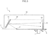
- the wedge 20 preferably includes an absorber 25 disposed at the front end 22 thereof for absorbing ultrasound, as shown in Fig. 3 .
- the use of the wedge 20 including the absorber 25 will reduce the reflection of ultrasound (i.e. ultrasound or surface waves S having propagated through the wedge 20 and reached the front end 22 of the wedge 20) at the front end 22 of the wedge 20, or ultrasonic echoes.
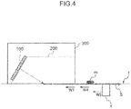
- the conventional inspection method uses an ultrasonic probe including a transducer 100, a wedge 200, and a casing 300.
- the ultrasonic probe is configured substantially the same as in the above-described embodiment except for the wedge length in a propagation direction of surface waves S.
- a receiver of the transducer 100 receives an ultrasonic echo W5 produced by reflection of the surface waves S by a defect f present in the part of a test object T in front of the wedge 200 in the propagation direction of the surface waves S.
- a couplant m such as oil
- W4 ultrasonic echo
- the receiver of the conventional inspection method receives a reception signal A3 based on an ultrasonic echo W3 produced by reflection of the ultrasound at a front end of the wedge 200, a reception signal A4 based on the ultrasonic echo W4 produced by the reflection of the surface waves S by the couplant m, and a reception signal A5 based on the ultrasonic echo W5 produced by the reflection of the surface waves S by the defect f.
- the inspection method according to the present embodiment detects the defect f present in the part of the surface area of the test object T overlapped with the wedge 20 (directly under the wedge).
- This allows a couplant m on the part of the surface of the test object T outside the part directly under the wedge to cause an ultrasonic echo (noise) that is to be detected outside the inspection zone.
- an ultrasonic echo noise
- the detection accuracy of the defect f is enhanced by the use of the wedge 20 including the absorber 25, as shown in Fig. 3 .
- the ultrasonic echo W1 is produced at the defect f before the surface waves S reach the front end 22 of the wedge 20, and therefore the absorber 25 hardly affects the production of the ultrasonic echo W1 caused by the defect f.
- the use of a wedge including an absorber would reduce the surface waves S propagating beyond the wedge. Consequently, the ultrasonic echo produced at the defect f would become considerably weaker.
- the use of the wedge 20 including the absorber 25 is particularly effective in the present inspection method of detecting the defect f present in the part directly under the wedge 20.
- a transducer including a transmitter and a transducer including a receiver may be configured as separate units.
- an ultrasonic probe 1 including an absorber 25 was used in the example.
- a wedge 20 has a dimension D of 10 mm from an incident point P to a front end 22.
- a transmitter transmitted ultrasound with a frequency of 2 MHz for four consecutive cycles.
- the reception signals detected at that time is shown in Fig. 7 .
- negative values of the detection signals are reflected as positive values.
- the wavelength ⁇ of surface waves S was about 1.5 mm.
- the signal ⁇ indicates transducer reverberations
- the signal ⁇ indicates a reception signal detected when a receiver received the front end-reflected ultrasonic echo W2.
- the inspection zone ranges from the signal ⁇ to the signal ⁇ (over about seven consecutive cycles in the example).
- a signal ⁇ was clearly detected in the inspection zone, the signal ⁇ indicating the reception by the receiver of an ultrasonic echo produced by reflection of the surface waves S by the horizontal hole.
- the wavelength of the ultrasound transmitted by the transmitter is desired to have a value falling in the range between the signal ⁇ and the signal ⁇ .
- the dimension D is set such that the inspection zone is equal to or greater than the wavelength of the ultrasound transmitted by the transmitter.
- the inspection zone is desired to have a length equal to or greater than the sum of the length of a pulse (four wavelength cycles in the example) transmitted by the transmitter and one wavelength.
- the inspection method is a method for inspecting a test object for defects using an ultrasonic probe that includes a transmitter for transmitting ultrasound, a wedge holding the transmitter at an angle allowing the ultrasound transmitted from the transmitter to propagate as surface waves along a surface area of the test object, and a receiver for receiving an ultrasonic echo produced by reflection of the ultrasound, the method comprising the steps of: placing the ultrasonic probe on the test object; transmitting the ultrasound from the transmitter into the wedge such that the surface waves propagate along the surface area of the test object; and determining that there is a defect in a part of the test object overlapped with the wedge when the receiver receives the ultrasonic echo, after the transmission of the ultrasound by the transmitter, in a time shorter than a time required to receive a front end-reflected ultrasonic echo produced by reflection of the surface waves at a front end of the wedge in a propagation direction of the surface waves.
- the present inspection method detects a defect present in the part of the surface area overlapped with the wedge (directly under the wedge).
- a couplant such as oil
- the couplant is in the form of a uniform film between the wedge and the test object.
- the couplant reflects almost no ultrasound.
- the time required before the receiver receives the front end-reflected ultrasonic echo can be uniquely determined by the structure of the ultrasonic probe.
- the present inspection method can reduce the ultrasonic echo (noise) caused by the couplant applied on the surface of the test object. This reduces false detections, thus improving the defect detection accuracy.
- the wedge in the wedge placing step, includes an absorber disposed at the front end thereof in the propagation direction for absorbing the ultrasound.
- the ultrasound transmitted from the transmitter propagates through the wedge and is reflected by the front end of the wedge to thereby also produce an ultrasonic echo.
- the ultrasound propagating through the wedge is liable to be detected as noise, because it is faster than the surface waves used for the inspection.
- the placement of the absorber at the front end reduces the noise, thus enhancing the defect detection accuracy.
- an ultrasonic echo is produced at the defect before the surface waves reach the front end of the wedge, and therefore the absorber hardly affects the production of the ultrasonic echo caused by the defect.
- use of a wedge including an absorber would reduce the surface waves propagating beyond the wedge. Consequently, the ultrasonic echo produced at the defect would become considerably weaker.
- the use of the wedge including the absorber is particularly effective in the present inspection method of detecting a defect present in the part directly under the wedge.
- the wedge is made of polyetherimide.
- the ultrasound propagates a long distance through the wedge, and is therefore greatly attenuated by the wedge.
- the wedge is preferably made of a material capable of preventing ultrasound attenuation.
- the material is also desired to have a high wear resistance. It is therefore desired to use a wedge made of polyetherimide meeting these conditions.
Landscapes
- Physics & Mathematics (AREA)
- Health & Medical Sciences (AREA)
- Life Sciences & Earth Sciences (AREA)
- Chemical & Material Sciences (AREA)
- Analytical Chemistry (AREA)
- Biochemistry (AREA)
- General Health & Medical Sciences (AREA)
- General Physics & Mathematics (AREA)
- Immunology (AREA)
- Pathology (AREA)
- Acoustics & Sound (AREA)
- Investigating Or Analyzing Materials By The Use Of Ultrasonic Waves (AREA)
Abstract
Description
- The present invention relates to a method for inspecting a test object for defects using an ultrasonic probe.
- Conventional nondestructive methods for inspecting a test object for defects include those using an ultrasonic probe. For example,
Patent Literature 1 discloses a method for inspecting a test object for defects present in a surface area (including the surface and near-surface) of the test object using an ultrasonic probe that includes a transducer having a transmitter and a receiver of ultrasound and a wedge holding the transducer. Specifically, the wedge holds the transmitter at an angle allowing the ultrasound transmitted from the transmitter to propagate as surface waves along the surface area of the test object. In this inspection method, the receiver receives an ultrasonic echo produced by the reflection of the surface waves by a defect present in the surface area of the test object, thereby allowing detection of the defect. The surface area refers to an area with a depth equal to about once or twice the wavelength of the surface waves from the surface of the test object. - In inspection methods such as the one described in
Patent Literature 1, the surface waves may also be reflected by a couplant, such as oil, or a foreign matter adhered to the part of the surface of a test object that lies in front of the wedge in the propagation direction of the surface waves. The produced ultrasonic echo will be received by the receiver as a signal. Thus, it is difficult to determine whether an ultrasonic echo received by the receiver is based on a defect or any foreign matter on the surface, which can lead to an increase in false detections of defects. In other words, such a conventional inspection method requires cleaning of the surface of the inspection zone during the inspection. This makes the supply of couplant troublesome and thus makes it difficult to obtain a reliable defect detection accuracy. - Patent Literature 1: Japanese Unexamined Patent Publication No.
2010-54497 - It is an object of the present invention to provide an inspection method that allows reliable inspection while improving the accuracy of detecting a defect present in a surface area of a test object.
- An inspection method according to an aspect of the present invention is a method for inspecting a test object for defects using an ultrasonic probe that includes a transmitter for transmitting ultrasound, a wedge holding the transmitter at an angle allowing the ultrasound transmitted from the transmitter to propagate as surface waves along a surface area of the test object, and a receiver for receiving an ultrasonic echo produced by reflection of the ultrasound, the method comprising the steps of: placing the ultrasonic probe on the test object; transmitting the ultrasound from the transmitter into the wedge such that the surface waves propagate along the surface area of the test object; and determining that there is a defect in a part of the test object overlapped with the wedge when the receiver receives the ultrasonic echo, after the transmission of the ultrasound by the transmitter, in a time shorter than a time required to receive a front end-reflected ultrasonic echo produced by reflection of the surface waves at a front end of the wedge in a propagation direction of the surface waves.
-
-
Fig. 1 is a schematic diagram of an inspection method according to an embodiment of the present invention. -
Fig. 2 is a diagram illustrating reception signals A1 and A2. -
Fig. 3 is a diagram showing a modification of the inspection method shown inFig. 1 . -
Fig. 4 is a schematic diagram of a conventional inspection method. -
Fig. 5 is a diagram illustrating reception signals A3, A4, and A5. -
Fig. 6 is a schematic diagram showing an ultrasonic probe and a test object in an example. -
Fig. 7 is a graph showing an inspection result of the example. - An inspection method according to an embodiment of the present invention will be described with reference to
Figs. 1 to 3 . The present inspection method uses surface waves S to detect a defect present on the surface and near-surface (hereinafter, referred to as "surface area") of a test object T, such as a steel material. The surface area refers to an area with a depth equal to about once or twice the wavelength of the surface waves S from the surface of the test object T. Specifically, the inspection method uses anultrasonic probe 1 that includes atransducer 10, awedge 20, and acasing 30 housing thetransducer 10 and thewedge 20, as shown inFig. 1 . - The
transducer 10 includes a transmitter for transmitting ultrasound and a receiver for receiving an ultrasonic echo produced by reflection of the ultrasound. - The
wedge 20 holds thetransducer 10 at an angle allowing the ultrasound transmitted from the transmitter to propagate as surface waves S (in the form of Rayleigh waves or SH waves) along the surface area of the test object T. Thewedge 20 is preferably made of polyetherimide or acrylic resin, and more preferably made of polyetherimide. - The present inspection method includes a placement step, an ultrasound transmission step, and a determination step.
- In the placement step, the
ultrasonic probe 1 is placed on the test object T. At this time, the gap between the contact surfaces of the test object T and theultrasonic probe 1 is filled with a couplant, such as oil, where theultrasonic probe 1 is pressed against the test object T such that the couplant forms a uniform thin film between the bottom surface of theultrasonic probe 1 and the test object T. - In the ultrasound transmission step, the transmitter of the
transducer 10 transmits ultrasound (shown by the dotted arrow inFig. 1 ). Part of the ultrasound travels straight through thewedge 20 and reaches an incident point P (i.e. the point of incidence at which the part of the ultrasound emitted from the center of thetransducer 10 enters the surface of the test object T). Subsequently, the part of the ultrasound propagates as surface waves S from the incident point P along the surface area of the test object T. Even when the couplant is between theultrasonic probe 1 and the test object T, it is in the form of a uniform thin film between theultrasonic probe 1 and the test object T. Thus, the couplant reflects almost no ultrasound. - In the determination step, it is determined whether there is a defect f in the part of the test object T overlapped with the wedge 20 (directly under the wedge 20). Specifically, at the determination step, it is determined that there is a defect f in the part of the test object T overlapped with the
wedge 20 when the receiver receives an ultrasonic echo W1, after the transmission of ultrasound by the transmitter, in a time shorter than the time required to receive a front end-reflected ultrasonic echo W2 (an ultrasonic echo produced by reflection of the surface waves S at afront end 22 of thewedge 20 in the propagation direction of the surface waves S). The reason why this determination is possible will be described with reference toFig. 2 . -
Fig. 2 illustrates a reception signal A1 that is detected when the receiver receives the ultrasonic echo W1 produced by the reflection of the surface waves S by the defect f and a reception signal A2 that is detected when the receiver receives the front end-reflected ultrasonic echo W2. As shown inFig. 2 , the reception signal A1 is detected earlier than the reception signal A2 by the receiver. Here, the time required to detect the reception signal A2 is measured in advance. This makes it possible to determine, when the receiver receives the reception signal A1 in a time shorter than the detection time for the reception signal A2 (i.e. the signal based on the front end-reflected ultrasonic echo W2), that the reception signal A1 is a signal based on the ultrasonic echo W2 produced by the reflection of the surface waves S by the defect f present directly under thewedge 20. - In the wedge placement step, the
wedge 20 preferably includes anabsorber 25 disposed at thefront end 22 thereof for absorbing ultrasound, as shown inFig. 3 . The use of thewedge 20 including theabsorber 25 will reduce the reflection of ultrasound (i.e. ultrasound or surface waves S having propagated through thewedge 20 and reached thefront end 22 of the wedge 20) at thefront end 22 of thewedge 20, or ultrasonic echoes. - Now, a conventional inspection method for detecting defects will be described with reference to
Figs. 4 and5 . - The conventional inspection method uses an ultrasonic probe including a
transducer 100, awedge 200, and acasing 300. The ultrasonic probe is configured substantially the same as in the above-described embodiment except for the wedge length in a propagation direction of surface waves S. In the conventional inspection method, a receiver of thetransducer 100 receives an ultrasonic echo W5 produced by reflection of the surface waves S by a defect f present in the part of a test object T in front of thewedge 200 in the propagation direction of the surface waves S. Here, on the surface of the test object T, there may also be a couplant m, such as oil, in front of thewedge 200 in the propagation direction of the surface waves S, in which case the receiver will also receive an ultrasonic echo W4 (noise) produced by reflection of the surface waves S by the couplant m. In other words, as shown inFig. 5 , the receiver of the conventional inspection method receives a reception signal A3 based on an ultrasonic echo W3 produced by reflection of the ultrasound at a front end of thewedge 200, a reception signal A4 based on the ultrasonic echo W4 produced by the reflection of the surface waves S by the couplant m, and a reception signal A5 based on the ultrasonic echo W5 produced by the reflection of the surface waves S by the defect f. This makes it difficult to determine whether a signal received by the receiver is based on the ultrasonic echo W5 caused by the defect f or the ultrasonic echo W4 caused by the couplant m. - In contrast to such a conventional method, the inspection method according to the present embodiment detects the defect f present in the part of the surface area of the test object T overlapped with the wedge 20 (directly under the wedge). This allows a couplant m on the part of the surface of the test object T outside the part directly under the wedge to cause an ultrasonic echo (noise) that is to be detected outside the inspection zone. Thus, it is possible to improve the accuracy of detecting the defect f present in the surface area of the test object T.
- In addition, the detection accuracy of the defect f is enhanced by the use of the
wedge 20 including theabsorber 25, as shown inFig. 3 . Specifically, in the present inspection method, the ultrasonic echo W1 is produced at the defect f before the surface waves S reach thefront end 22 of thewedge 20, and therefore the absorber 25 hardly affects the production of the ultrasonic echo W1 caused by the defect f. However, in the case of detecting the defect f in front of thewedge 200 in the propagation direction as in the above-described conventional method, use of a wedge including an absorber would reduce the surface waves S propagating beyond the wedge. Consequently, the ultrasonic echo produced at the defect f would become considerably weaker. Thus, the use of thewedge 20 including theabsorber 25 is particularly effective in the present inspection method of detecting the defect f present in the part directly under thewedge 20. - The disclosed embodiment is exemplary in all respects and should not be regarded as restrictive. The scope of the present invention is indicated by the scope of the claims and not by the description of the embodiment provided above, and includes all modifications within the same sense and scope as the claims.
- For example, a transducer including a transmitter and a transducer including a receiver may be configured as separate units.
- Now, an example of the present inspection method will be described with reference to
Figs. 6 and7 . - As shown in
Fig. 6 , anultrasonic probe 1 including anabsorber 25 was used in the example. Awedge 20 has a dimension D of 10 mm from an incident point P to afront end 22. A steel material, having a horizontal hole (flat bottom hole) as a defect f, was used as a test object T. In the example, a transmitter transmitted ultrasound with a frequency of 2 MHz for four consecutive cycles. The reception signals detected at that time is shown inFig. 7 . InFig. 7 , negative values of the detection signals are reflected as positive values. In the example, because the test object T was a steel material, the wavelength λ of surface waves S was about 1.5 mm. - In
Fig. 7 , the signal α indicates transducer reverberations, and the signal γ indicates a reception signal detected when a receiver received the front end-reflected ultrasonic echo W2. Thus, the inspection zone ranges from the signal α to the signal γ (over about seven consecutive cycles in the example). In the example, a signal β was clearly detected in the inspection zone, the signal β indicating the reception by the receiver of an ultrasonic echo produced by reflection of the surface waves S by the horizontal hole. - As can be seen from the above result, the wavelength of the ultrasound transmitted by the transmitter is desired to have a value falling in the range between the signal α and the signal γ. In other words, the dimension D is set such that the inspection zone is equal to or greater than the wavelength of the ultrasound transmitted by the transmitter. The inspection zone is desired to have a length equal to or greater than the sum of the length of a pulse (four wavelength cycles in the example) transmitted by the transmitter and one wavelength.
- The described embodiment will now be summarized.
- The inspection method according to the above-described embodiment is a method for inspecting a test object for defects using an ultrasonic probe that includes a transmitter for transmitting ultrasound, a wedge holding the transmitter at an angle allowing the ultrasound transmitted from the transmitter to propagate as surface waves along a surface area of the test object, and a receiver for receiving an ultrasonic echo produced by reflection of the ultrasound, the method comprising the steps of: placing the ultrasonic probe on the test object; transmitting the ultrasound from the transmitter into the wedge such that the surface waves propagate along the surface area of the test object; and determining that there is a defect in a part of the test object overlapped with the wedge when the receiver receives the ultrasonic echo, after the transmission of the ultrasound by the transmitter, in a time shorter than a time required to receive a front end-reflected ultrasonic echo produced by reflection of the surface waves at a front end of the wedge in a propagation direction of the surface waves.
- Unlike the conventional method which detects a defect present in the part of the surface area of the test object in front of the wedge in the propagation direction of the surface waves, the present inspection method detects a defect present in the part of the surface area overlapped with the wedge (directly under the wedge). Here, even when a couplant, such as oil, is between the wedge and the test object, the couplant is in the form of a uniform film between the wedge and the test object. Thus, the couplant reflects almost no ultrasound. In addition, the time required before the receiver receives the front end-reflected ultrasonic echo can be uniquely determined by the structure of the ultrasonic probe. This makes it possible, when the receiver receives an ultrasonic echo, after the transmission of ultrasound by the transmitter, in a time shorter than the time required to receive the front end-reflected ultrasonic echo, to determine that the ultrasonic echo has been produced by reflection of the surface waves by the defect present directly under the wedge, i.e. there is a defect in the part of the test object overlapped with the wedge. As can be seen from the above, the present inspection method can reduce the ultrasonic echo (noise) caused by the couplant applied on the surface of the test object. This reduces false detections, thus improving the defect detection accuracy.
- In this case, it is preferred that in the wedge placing step, the wedge includes an absorber disposed at the front end thereof in the propagation direction for absorbing the ultrasound.
- The ultrasound transmitted from the transmitter propagates through the wedge and is reflected by the front end of the wedge to thereby also produce an ultrasonic echo. The ultrasound propagating through the wedge is liable to be detected as noise, because it is faster than the surface waves used for the inspection. However, the placement of the absorber at the front end reduces the noise, thus enhancing the defect detection accuracy. Specifically, in the present inspection method, an ultrasonic echo is produced at the defect before the surface waves reach the front end of the wedge, and therefore the absorber hardly affects the production of the ultrasonic echo caused by the defect. However, in the case of detecting a defect in front of the wedge in the propagation direction as in the conventional method, use of a wedge including an absorber would reduce the surface waves propagating beyond the wedge. Consequently, the ultrasonic echo produced at the defect would become considerably weaker. Thus, the use of the wedge including the absorber is particularly effective in the present inspection method of detecting a defect present in the part directly under the wedge.
- It is also preferred in the above-described inspection method that in the wedge placing step, the wedge is made of polyetherimide.
- In the method according to the present invention, the ultrasound propagates a long distance through the wedge, and is therefore greatly attenuated by the wedge. Thus, the wedge is preferably made of a material capable of preventing ultrasound attenuation. For the contact inspection method, the material is also desired to have a high wear resistance. It is therefore desired to use a wedge made of polyetherimide meeting these conditions.
Claims (3)
- A method for inspecting a test object for defects using an ultrasonic probe that includes a transmitter for transmitting ultrasound, a wedge holding the transmitter at an angle allowing the ultrasound transmitted from the transmitter to propagate as surface waves along a surface area of the test object, and a receiver for receiving an ultrasonic echo produced by reflection of the ultrasound, the method comprising the steps of:placing the ultrasonic probe on the test object;transmitting the ultrasound from the transmitter into the wedge such that the surface waves propagate along the surface area of the test object; anddetermining that there is a defect in a part of the test object overlapped with the wedge when the receiver receives the ultrasonic echo, after the transmission of the ultrasound by the transmitter, in a time shorter than a time required to receive a front end-reflected ultrasonic echo produced by reflection of the surface waves at a front end of the wedge in a propagation direction of the surface waves.
- The method according to claim 1, wherein
in the wedge placing step, the wedge includes an absorber disposed at the front end thereof in the propagation direction for absorbing the ultrasound. - The method according to claims 1 or 2, wherein
in the wedge placing step, the wedge is made of polyetherimide.
Applications Claiming Priority (2)
| Application Number | Priority Date | Filing Date | Title |
|---|---|---|---|
| JP2017007431A JP6731863B2 (en) | 2017-01-19 | 2017-01-19 | Inspection method |
| PCT/JP2017/046352 WO2018135242A1 (en) | 2017-01-19 | 2017-12-25 | Inspection method |
Publications (2)
| Publication Number | Publication Date |
|---|---|
| EP3543688A1 true EP3543688A1 (en) | 2019-09-25 |
| EP3543688A4 EP3543688A4 (en) | 2020-07-01 |
Family
ID=62908945
Family Applications (1)
| Application Number | Title | Priority Date | Filing Date |
|---|---|---|---|
| EP17892411.4A Withdrawn EP3543688A4 (en) | 2017-01-19 | 2017-12-25 | VERIFICATION PROCEDURE |
Country Status (4)
| Country | Link |
|---|---|
| US (1) | US11054399B2 (en) |
| EP (1) | EP3543688A4 (en) |
| JP (1) | JP6731863B2 (en) |
| WO (1) | WO2018135242A1 (en) |
Families Citing this family (1)
| Publication number | Priority date | Publication date | Assignee | Title |
|---|---|---|---|---|
| CN111781274B (en) * | 2020-07-22 | 2023-07-11 | 长沙理工大学 | A Leaky Surface Wave Ultrasonic Imaging Method Based on Block Scanning and Attenuation Compensation |
Family Cites Families (24)
| Publication number | Priority date | Publication date | Assignee | Title |
|---|---|---|---|---|
| US2667780A (en) * | 1951-07-26 | 1954-02-02 | Sperry Prod Inc | Ultrasonic inspection device |
| US3996791A (en) * | 1975-04-24 | 1976-12-14 | Krautkramer-Branson, Incorporated | Ultrasonic test method and apparatus utilizing scattered signals |
| US4289030A (en) * | 1979-08-01 | 1981-09-15 | Rockwell International Corporation | Nondestructive testing utilizing horizontally polarized shear waves |
| JPS57171512U (en) * | 1981-04-23 | 1982-10-28 | ||
| US4658649A (en) * | 1985-06-06 | 1987-04-21 | Combustion Engineering, Inc. | Ultrasonic method and device for detecting and measuring defects in metal media |
| JPS63261151A (en) * | 1987-04-17 | 1988-10-27 | Ishikawajima Harima Heavy Ind Co Ltd | Ultrasonic probe |
| JP3052550B2 (en) * | 1992-03-30 | 2000-06-12 | 関東特殊製鋼株式会社 | Bevel probe for ultrasonic flaw detection |
| JPH11133005A (en) * | 1997-10-31 | 1999-05-21 | Kawasaki Steel Corp | Surface wave probe for roll inspection and its incident angle setting method |
| JP3724231B2 (en) * | 1997-12-01 | 2005-12-07 | Jfeスチール株式会社 | Ultrasonic flaw detection method and apparatus for cylindrical body, and roll grinding method using the same |
| JPH11326289A (en) * | 1998-05-12 | 1999-11-26 | Kawasaki Steel Corp | Ultrasonic flaw detection method and apparatus for cylindrical body |
| DE19849102C1 (en) * | 1998-10-24 | 2000-07-20 | Nukem Nutronik Gmbh | Method and device for the non-destructive testing of objects for open and / or near-surface defects |
| JP2002277447A (en) * | 2001-03-19 | 2002-09-25 | Kawasaki Steel Corp | Ultrasonic flaw detection method and apparatus |
| JP2003161613A (en) * | 2001-11-27 | 2003-06-06 | Nisshin Kogyo Kk | Defect detection method for concrete structures |
| JP2005156333A (en) * | 2003-11-25 | 2005-06-16 | Nisshin Kogyo Kk | Defect detection method for cylindrical structures |
| JP4885631B2 (en) * | 2006-07-10 | 2012-02-29 | 三菱電機株式会社 | Ultrasonic flaw detection apparatus and ultrasonic flaw detection method |
| AU2009223322B2 (en) * | 2008-03-14 | 2014-08-14 | Expro Meters, Inc. | Method and apparatus for determining pipewall thickness using one or more ultrasonic sensors |
| JP5235112B2 (en) * | 2008-07-25 | 2013-07-10 | 古野電気株式会社 | Shape detection device, shape detection method, and bone strength diagnosis device using shape detection device |
| JP5633059B2 (en) | 2008-07-31 | 2014-12-03 | 三菱電機株式会社 | Ultrasonic flaw detection sensitivity setting method and ultrasonic flaw detection apparatus |
| GB0903232D0 (en) * | 2009-02-25 | 2009-04-08 | Saipem Spa | A method for testing pipeline welds |
| JP5420525B2 (en) * | 2010-11-30 | 2014-02-19 | 株式会社神戸製鋼所 | Apparatus and method for ultrasonic inspection of small diameter tube |
| JP5627563B2 (en) * | 2011-12-14 | 2014-11-19 | 株式会社神戸製鋼所 | Surface flaw detection apparatus and surface flaw detection method |
| JP5642248B2 (en) * | 2013-02-14 | 2014-12-17 | 株式会社神戸製鋼所 | Ultrasonic probe |
| FR3011637B1 (en) * | 2013-10-07 | 2015-12-11 | Centre Nat Etd Spatiales | ACOUSTIC DETECTOR OF A PEA MEASURING CELL; CELL AND METHOD THEREFOR. |
| US9964526B2 (en) * | 2015-03-31 | 2018-05-08 | Olympus Scientific Solutions Americas Inc. | Phased-array probe and a phased-array search unit |
-
2017
- 2017-01-19 JP JP2017007431A patent/JP6731863B2/en active Active
- 2017-12-25 EP EP17892411.4A patent/EP3543688A4/en not_active Withdrawn
- 2017-12-25 WO PCT/JP2017/046352 patent/WO2018135242A1/en not_active Ceased
- 2017-12-25 US US16/466,081 patent/US11054399B2/en active Active
Also Published As
| Publication number | Publication date |
|---|---|
| JP6731863B2 (en) | 2020-07-29 |
| JP2018115979A (en) | 2018-07-26 |
| WO2018135242A1 (en) | 2018-07-26 |
| EP3543688A4 (en) | 2020-07-01 |
| US11054399B2 (en) | 2021-07-06 |
| US20200064309A1 (en) | 2020-02-27 |
Similar Documents
| Publication | Publication Date | Title |
|---|---|---|
| US10481131B2 (en) | Ultrasonic test system, ultrasonic test method and method of manufacturing aircraft part | |
| US20130179098A1 (en) | Processing signals acquired during guided wave testing | |
| CN106596725B (en) | An Ultrasonic Identification Method for R-Zone Defects in Composite Material Structures | |
| EP1271097A2 (en) | Method for inspecting clad pipe | |
| EP3543689A1 (en) | Ultrasonic probe | |
| US11054399B2 (en) | Inspection method | |
| WO2019150952A1 (en) | Defect detecting method | |
| JP6830630B2 (en) | Ultrasonic inspection method and ultrasonic inspection equipment | |
| KR101113095B1 (en) | Ultrasonic measuring apparatus for nondestructive inspection | |
| JP2006023215A (en) | Ultrasonic inspection method, ultrasonic inspection apparatus, and guide wave transducer of the apparatus | |
| JP2002277447A (en) | Ultrasonic flaw detection method and apparatus | |
| JP3810661B2 (en) | Defect detection method for piping | |
| JP2006177872A (en) | Ultrasonic flaw detection method and ultrasonic flaw detection apparatus | |
| RU2791670C1 (en) | Method for checking quality of acoustic contact between ultrasonic transducer and ceramic product during ultrasonic flaw detection | |
| JPH1151909A (en) | Ultrasonic flaw detection method | |
| RU2789814C1 (en) | Method for defect determination of hydro-acoustic coating applied on underwater object | |
| JP2922508B1 (en) | Automatic ultrasonic flaw detector | |
| JP4143527B2 (en) | Thin plate ultrasonic flaw detector | |
| JP2005181170A (en) | Method for evaluating adhesion of coating materials | |
| JP2019132748A (en) | Ultrasonic probe | |
| CA3044105A1 (en) | Method and device for checking an object for flaws | |
| EP4086620A1 (en) | Method and device for checking the wall of a pipeline for flaws | |
| JP6016759B2 (en) | Ultrasonic flaw detector | |
| RU2614195C2 (en) | Methods of measuring ultrasonic signal parameters in presence of interference | |
| KR20100073849A (en) | System and method for detecting damage of gear tooth using ultrasonic |
Legal Events
| Date | Code | Title | Description |
|---|---|---|---|
| STAA | Information on the status of an ep patent application or granted ep patent |
Free format text: STATUS: THE INTERNATIONAL PUBLICATION HAS BEEN MADE |
|
| PUAI | Public reference made under article 153(3) epc to a published international application that has entered the european phase |
Free format text: ORIGINAL CODE: 0009012 |
|
| STAA | Information on the status of an ep patent application or granted ep patent |
Free format text: STATUS: REQUEST FOR EXAMINATION WAS MADE |
|
| 17P | Request for examination filed |
Effective date: 20190618 |
|
| AK | Designated contracting states |
Kind code of ref document: A1 Designated state(s): AL AT BE BG CH CY CZ DE DK EE ES FI FR GB GR HR HU IE IS IT LI LT LU LV MC MK MT NL NO PL PT RO RS SE SI SK SM TR |
|
| AX | Request for extension of the european patent |
Extension state: BA ME |
|
| DAV | Request for validation of the european patent (deleted) | ||
| DAX | Request for extension of the european patent (deleted) | ||
| A4 | Supplementary search report drawn up and despatched |
Effective date: 20200529 |
|
| RIC1 | Information provided on ipc code assigned before grant |
Ipc: G01N 29/28 20060101ALI20200525BHEP Ipc: G01N 29/22 20060101ALI20200525BHEP Ipc: G01N 29/07 20060101AFI20200525BHEP Ipc: G01N 29/04 20060101ALI20200525BHEP |
|
| STAA | Information on the status of an ep patent application or granted ep patent |
Free format text: STATUS: EXAMINATION IS IN PROGRESS |
|
| 17Q | First examination report despatched |
Effective date: 20221103 |
|
| GRAP | Despatch of communication of intention to grant a patent |
Free format text: ORIGINAL CODE: EPIDOSNIGR1 |
|
| STAA | Information on the status of an ep patent application or granted ep patent |
Free format text: STATUS: GRANT OF PATENT IS INTENDED |
|
| INTG | Intention to grant announced |
Effective date: 20250129 |
|
| STAA | Information on the status of an ep patent application or granted ep patent |
Free format text: STATUS: THE APPLICATION IS DEEMED TO BE WITHDRAWN |
|
| 18D | Application deemed to be withdrawn |
Effective date: 20250531 |