EP3543153B1 - Machine a emballer sous vide des produits alimentaires dans des sacs - Google Patents
Machine a emballer sous vide des produits alimentaires dans des sacs Download PDFInfo
- Publication number
- EP3543153B1 EP3543153B1 EP19163839.4A EP19163839A EP3543153B1 EP 3543153 B1 EP3543153 B1 EP 3543153B1 EP 19163839 A EP19163839 A EP 19163839A EP 3543153 B1 EP3543153 B1 EP 3543153B1
- Authority
- EP
- European Patent Office
- Prior art keywords
- seat
- engagement pin
- engagement
- machine according
- lid
- Prior art date
- Legal status (The legal status is an assumption and is not a legal conclusion. Google has not performed a legal analysis and makes no representation as to the accuracy of the status listed.)
- Active
Links
- 235000013305 food Nutrition 0.000 title claims description 15
- 238000004806 packaging method and process Methods 0.000 title claims description 11
- 230000008878 coupling Effects 0.000 claims description 31
- 238000010168 coupling process Methods 0.000 claims description 31
- 238000005859 coupling reaction Methods 0.000 claims description 31
- 238000003780 insertion Methods 0.000 claims description 18
- 230000037431 insertion Effects 0.000 claims description 18
- 230000013011 mating Effects 0.000 claims description 18
- 230000014759 maintenance of location Effects 0.000 claims description 17
- 238000007789 sealing Methods 0.000 claims description 12
- 238000009461 vacuum packaging Methods 0.000 claims description 7
- 238000013519 translation Methods 0.000 claims description 4
- XAGFODPZIPBFFR-UHFFFAOYSA-N aluminium Chemical compound [Al] XAGFODPZIPBFFR-UHFFFAOYSA-N 0.000 description 4
- 239000000463 material Substances 0.000 description 4
- 229910052782 aluminium Inorganic materials 0.000 description 3
- 238000004140 cleaning Methods 0.000 description 3
- 239000007769 metal material Substances 0.000 description 3
- 229920003023 plastic Polymers 0.000 description 3
- 125000006850 spacer group Chemical group 0.000 description 3
- 238000004873 anchoring Methods 0.000 description 2
- 239000007788 liquid Substances 0.000 description 2
- 238000012423 maintenance Methods 0.000 description 2
- 230000036961 partial effect Effects 0.000 description 2
- 239000004033 plastic Substances 0.000 description 2
- 229920003229 poly(methyl methacrylate) Polymers 0.000 description 2
- 239000004926 polymethyl methacrylate Substances 0.000 description 2
- 230000007704 transition Effects 0.000 description 2
- 229910000838 Al alloy Inorganic materials 0.000 description 1
- 229910001297 Zn alloy Inorganic materials 0.000 description 1
- 230000004308 accommodation Effects 0.000 description 1
- 230000009471 action Effects 0.000 description 1
- 230000004913 activation Effects 0.000 description 1
- 239000000853 adhesive Substances 0.000 description 1
- 230000001070 adhesive effect Effects 0.000 description 1
- 238000009835 boiling Methods 0.000 description 1
- 230000002860 competitive effect Effects 0.000 description 1
- 230000001419 dependent effect Effects 0.000 description 1
- 230000008021 deposition Effects 0.000 description 1
- 238000000605 extraction Methods 0.000 description 1
- 238000007373 indentation Methods 0.000 description 1
- 230000010354 integration Effects 0.000 description 1
- 230000000670 limiting effect Effects 0.000 description 1
- 235000021056 liquid food Nutrition 0.000 description 1
- 238000012986 modification Methods 0.000 description 1
- 230000004048 modification Effects 0.000 description 1
- 238000012544 monitoring process Methods 0.000 description 1
- 230000000717 retained effect Effects 0.000 description 1
- 238000011012 sanitization Methods 0.000 description 1
- 239000010935 stainless steel Substances 0.000 description 1
- 229910001220 stainless steel Inorganic materials 0.000 description 1
- 239000012815 thermoplastic material Substances 0.000 description 1
Images


Classifications
-
- B—PERFORMING OPERATIONS; TRANSPORTING
- B65—CONVEYING; PACKING; STORING; HANDLING THIN OR FILAMENTARY MATERIAL
- B65B—MACHINES, APPARATUS OR DEVICES FOR, OR METHODS OF, PACKAGING ARTICLES OR MATERIALS; UNPACKING
- B65B31/00—Packaging articles or materials under special atmospheric or gaseous conditions; Adding propellants to aerosol containers
- B65B31/02—Filling, closing, or filling and closing, containers or wrappers in chambers maintained under vacuum or superatmospheric pressure or containing a special atmosphere, e.g. of inert gas
- B65B31/024—Filling, closing, or filling and closing, containers or wrappers in chambers maintained under vacuum or superatmospheric pressure or containing a special atmosphere, e.g. of inert gas specially adapted for wrappers or bags
-
- B—PERFORMING OPERATIONS; TRANSPORTING
- B29—WORKING OF PLASTICS; WORKING OF SUBSTANCES IN A PLASTIC STATE IN GENERAL
- B29C—SHAPING OR JOINING OF PLASTICS; SHAPING OF MATERIAL IN A PLASTIC STATE, NOT OTHERWISE PROVIDED FOR; AFTER-TREATMENT OF THE SHAPED PRODUCTS, e.g. REPAIRING
- B29C65/00—Joining or sealing of preformed parts, e.g. welding of plastics materials; Apparatus therefor
- B29C65/02—Joining or sealing of preformed parts, e.g. welding of plastics materials; Apparatus therefor by heating, with or without pressure
-
- B—PERFORMING OPERATIONS; TRANSPORTING
- B29—WORKING OF PLASTICS; WORKING OF SUBSTANCES IN A PLASTIC STATE IN GENERAL
- B29C—SHAPING OR JOINING OF PLASTICS; SHAPING OF MATERIAL IN A PLASTIC STATE, NOT OTHERWISE PROVIDED FOR; AFTER-TREATMENT OF THE SHAPED PRODUCTS, e.g. REPAIRING
- B29C66/00—General aspects of processes or apparatus for joining preformed parts
- B29C66/01—General aspects dealing with the joint area or with the area to be joined
- B29C66/05—Particular design of joint configurations
- B29C66/10—Particular design of joint configurations particular design of the joint cross-sections
- B29C66/11—Joint cross-sections comprising a single joint-segment, i.e. one of the parts to be joined comprising a single joint-segment in the joint cross-section
- B29C66/112—Single lapped joints
- B29C66/1122—Single lap to lap joints, i.e. overlap joints
-
- B—PERFORMING OPERATIONS; TRANSPORTING
- B29—WORKING OF PLASTICS; WORKING OF SUBSTANCES IN A PLASTIC STATE IN GENERAL
- B29C—SHAPING OR JOINING OF PLASTICS; SHAPING OF MATERIAL IN A PLASTIC STATE, NOT OTHERWISE PROVIDED FOR; AFTER-TREATMENT OF THE SHAPED PRODUCTS, e.g. REPAIRING
- B29C66/00—General aspects of processes or apparatus for joining preformed parts
- B29C66/40—General aspects of joining substantially flat articles, e.g. plates, sheets or web-like materials; Making flat seams in tubular or hollow articles; Joining single elements to substantially flat surfaces
- B29C66/41—Joining substantially flat articles ; Making flat seams in tubular or hollow articles
- B29C66/43—Joining a relatively small portion of the surface of said articles
- B29C66/431—Joining the articles to themselves
- B29C66/4312—Joining the articles to themselves for making flat seams in tubular or hollow articles, e.g. transversal seams
- B29C66/43121—Closing the ends of tubular or hollow single articles, e.g. closing the ends of bags
-
- B—PERFORMING OPERATIONS; TRANSPORTING
- B29—WORKING OF PLASTICS; WORKING OF SUBSTANCES IN A PLASTIC STATE IN GENERAL
- B29C—SHAPING OR JOINING OF PLASTICS; SHAPING OF MATERIAL IN A PLASTIC STATE, NOT OTHERWISE PROVIDED FOR; AFTER-TREATMENT OF THE SHAPED PRODUCTS, e.g. REPAIRING
- B29C66/00—General aspects of processes or apparatus for joining preformed parts
- B29C66/80—General aspects of machine operations or constructions and parts thereof
- B29C66/81—General aspects of the pressing elements, i.e. the elements applying pressure on the parts to be joined in the area to be joined, e.g. the welding jaws or clamps
- B29C66/816—General aspects of the pressing elements, i.e. the elements applying pressure on the parts to be joined in the area to be joined, e.g. the welding jaws or clamps characterised by the mounting of the pressing elements, e.g. of the welding jaws or clamps
- B29C66/8167—Quick change joining tools or surfaces
-
- B—PERFORMING OPERATIONS; TRANSPORTING
- B29—WORKING OF PLASTICS; WORKING OF SUBSTANCES IN A PLASTIC STATE IN GENERAL
- B29C—SHAPING OR JOINING OF PLASTICS; SHAPING OF MATERIAL IN A PLASTIC STATE, NOT OTHERWISE PROVIDED FOR; AFTER-TREATMENT OF THE SHAPED PRODUCTS, e.g. REPAIRING
- B29C66/00—General aspects of processes or apparatus for joining preformed parts
- B29C66/80—General aspects of machine operations or constructions and parts thereof
- B29C66/82—Pressure application arrangements, e.g. transmission or actuating mechanisms for joining tools or clamps
- B29C66/822—Transmission mechanisms
- B29C66/8221—Scissor or lever mechanisms, i.e. involving a pivot point
-
- B—PERFORMING OPERATIONS; TRANSPORTING
- B29—WORKING OF PLASTICS; WORKING OF SUBSTANCES IN A PLASTIC STATE IN GENERAL
- B29C—SHAPING OR JOINING OF PLASTICS; SHAPING OF MATERIAL IN A PLASTIC STATE, NOT OTHERWISE PROVIDED FOR; AFTER-TREATMENT OF THE SHAPED PRODUCTS, e.g. REPAIRING
- B29C66/00—General aspects of processes or apparatus for joining preformed parts
- B29C66/80—General aspects of machine operations or constructions and parts thereof
- B29C66/83—General aspects of machine operations or constructions and parts thereof characterised by the movement of the joining or pressing tools
- B29C66/832—Reciprocating joining or pressing tools
- B29C66/8324—Joining or pressing tools pivoting around one axis
-
- B—PERFORMING OPERATIONS; TRANSPORTING
- B29—WORKING OF PLASTICS; WORKING OF SUBSTANCES IN A PLASTIC STATE IN GENERAL
- B29C—SHAPING OR JOINING OF PLASTICS; SHAPING OF MATERIAL IN A PLASTIC STATE, NOT OTHERWISE PROVIDED FOR; AFTER-TREATMENT OF THE SHAPED PRODUCTS, e.g. REPAIRING
- B29C66/00—General aspects of processes or apparatus for joining preformed parts
- B29C66/80—General aspects of machine operations or constructions and parts thereof
- B29C66/84—Specific machine types or machines suitable for specific applications
- B29C66/849—Packaging machines
-
- B—PERFORMING OPERATIONS; TRANSPORTING
- B65—CONVEYING; PACKING; STORING; HANDLING THIN OR FILAMENTARY MATERIAL
- B65B—MACHINES, APPARATUS OR DEVICES FOR, OR METHODS OF, PACKAGING ARTICLES OR MATERIALS; UNPACKING
- B65B51/00—Devices for, or methods of, sealing or securing package folds or closures; Devices for gathering or twisting wrappers, or necks of bags
- B65B51/10—Applying or generating heat or pressure or combinations thereof
- B65B51/14—Applying or generating heat or pressure or combinations thereof by reciprocating or oscillating members
- B65B51/146—Closing bags
-
- B—PERFORMING OPERATIONS; TRANSPORTING
- B65—CONVEYING; PACKING; STORING; HANDLING THIN OR FILAMENTARY MATERIAL
- B65B—MACHINES, APPARATUS OR DEVICES FOR, OR METHODS OF, PACKAGING ARTICLES OR MATERIALS; UNPACKING
- B65B59/00—Arrangements to enable machines to handle articles of different sizes, to produce packages of different sizes, to vary the contents of packages, to handle different types of packaging material, or to give access for cleaning or maintenance purposes
- B65B59/04—Machines constructed with readily-detachable units or assemblies, e.g. to facilitate maintenance
Definitions
- the present invention relates to a machine for packaging food products in vacuum bags.
- vacuum packaging machines are commercially available which have a base structure in which there is a vacuum chamber, which can be closed by means of a lid and in which a suitable container is placed which is constituted generally by a sealable bag, formed by sheets of plastic material, in which food products to be vacuum packaged are inserted.
- vacuum is created in the vacuum chamber by means of the activation of a vacuum pump.
- a heat-sealing bar constituted typically by a heat-sealing bar, usually supported by the base structure of the machine, and by a contrast bar, in turn supported by the lid, between which it is possible to interpose a portion of the bag.
- the heat-sealing bag is provided with an electric resistance heater and can move in the direction of the contrast bar, so as to be able to press the bag against the contrast bar, and allows to be able to seal it subsequently, by heat-sealing its sheets made of plastic material, as a consequence of the electric power supply of its electric resistance heater
- An exemplary prior art vacuum packaging machine is disclosed in document WO02/10017 .
- the lid of the vacuum chamber can be made of transparent plastic material, such as for example polymethyl methacrylate (PMMA), or of metallic material, such as stainless steel or aluminum.
- PMMA polymethyl methacrylate
- metallic material such as stainless steel or aluminum.
- the lid is sometimes provided with windows for monitoring the packaging cycle.
- the contrast bars are mounted on the lids in a nonremovable manner by means of screws and adhesive elements or by means of their integration in the body of the lid.
- the aim of the present invention is to provide a machine for packaging food products in vacuum bags that is capable of improving the background art in one or more of the aspects indicated above.
- an object of the invention is to provide a machine for packaging food products in vacuum bags that is capable of meeting in a simple and practical manner the cleaning and maintenance requirements of the machine.
- Another object of the invention is to provide a vacuum packaging machine that is convenient and easy to use.
- a further object of the invention is to provide a machine for packaging food products in vacuum bags that is capable of giving the greatest assurances of reliability and safety in use.
- a further object of the present invention is to overcome the drawbacks of the background art in a manner that is alternative to any existing solutions.
- Another object of the invention is to provide a machine for packaging food products in vacuum bags that is constructively simple to provide and can be obtained at highly competitive costs.
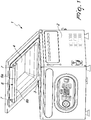
- the machine for packaging food products in vacuum bags designated generally by the reference numeral 1, comprises a base structure 2 in which there is a vacuum chamber 3 which is designed to accommodate a bag for the vacuum packaging of food products and can be closed by means of a lid 4, conveniently hinged to the base structure 2.
- the machine is further provided with means for sealing the bag, which comprise a heat-sealing bar 5, associated with the base structure 2, and a contrast bar 6, associated with the lid 4, between which it is possible to interpose a portion of the bag, in particular its portion proximate to its access mouth, so as to be able to seal it by heat-sealing.
- means for sealing the bag which comprise a heat-sealing bar 5, associated with the base structure 2, and a contrast bar 6, associated with the lid 4, between which it is possible to interpose a portion of the bag, in particular its portion proximate to its access mouth, so as to be able to seal it by heat-sealing.
- the contrast bar 6 is associated with the lid 4 detachably by means of at least one quick coupling/uncoupling device 7.
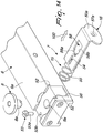
- the contrast bar 6 can be provided by means of a profiled element 6a, made of metallic material, such as for example aluminum, and having a transverse cross-section that is contoured to accommodate a contrast body 6b, made of elastically flexible material, such as rubber or the like, and designed to make contact with the portion of the bag to be sealed.
- a profiled element 6a made of metallic material, such as for example aluminum, and having a transverse cross-section that is contoured to accommodate a contrast body 6b, made of elastically flexible material, such as rubber or the like, and designed to make contact with the portion of the bag to be sealed.
- Each one of the quick coupling/uncoupling devices 7 comprises male mating means 8, which can engage female mating means 9, and retention means 10, which allowed to keep the male mating means 8 engaged with the female mating means 9.
- Each quick coupling/uncoupling device 7 is furthermore provided with actuation means 11 which can be activated by the user to deactivate the retention means 10 and thus allow the disengagement of the male mating means 8 from the female mating means 9.
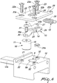
- the female mating means 9 comprise a seat 9a which is formed in a coupling body 12 arranged on the contrast bar 6.
- the coupling body 12 may be provided as a separate part with respect to the contrast bar 6, as in the example of Figures 1 to 10 , and in this case it is conveniently made of metallic material, such as for example aluminum or aluminum and zinc alloys, or of thermoplastic material with high mechanical strength and is advantageously coupled to the profiled element 6a for example by means of the axial insertion of a mating portion 12a thereof within the profiled element 6a, and rigidly anchored thereto by virtue of fixing means which are constituted for example by screws 12b or the like, which pass through the coupling body 12 to be screwed at the end to the contrast bar 6, at respective engagement portions formed on the profiled element 6a, and allow to optionally fix also a terminal closure plate 13 of the profiled element 6a.
- metallic material such as for example aluminum or aluminum and zinc alloys
- thermoplastic material with high mechanical strength
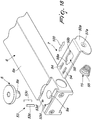
- the coupling body 12 can also be provided monolithically with respect to the contrast bar 6, as in the constructive variation shown in Figures 11 and 12 .
- the male mating means 8 comprise an engagement pin 8a, which is connected to the lid 4 and can be engaged detachably with the seat 9a.
- the retention means 10 comprise, at the seat 9a, a retention element 14, which is pushed by elastic means 15 in order to retain the engagement pin 8a in the seat 9a and can move in contrast with the elastic means 15 in order to allow the insertion of the engagement pin 8a in the seat 9a.
- the actuation means 11 comprise a button 16, which can be actuated by the user to actuate the movement of the retention element 14 in disengagement from the engagement pin 8a, so as to allow the disengagement of the engagement pin 8a from the seat 9a.
- the engagement pin 8a has, on its lateral surface, a groove 17, for example having an annular extension, which can be engaged by the retention element 14 in order to prevent the disengagement of the engagement pin 8a from the seat 9a.
- the retention element 14 is conveniently constituted by a lever body 18, which can rotate with respect to the contrast bar 6 and more particularly with respect to the coupling body 12.
- the button 16 comprises an actuation end 18a of the lever body 18, to which a maneuvering pin 19, which is conveniently knurled, is fixed.
- the lever body 18 has a through opening 20 and can be moved between a locking position, in which it affects, with at least one portion thereof, the seat 9a, and a release position, in which the through opening 20 is substantially aligned with the seat 9a.
- the lever body 18 is provided by a plate-like element accommodated in a hollow 21, which is formed on the face of the coupling body 12 that is crossed by the seat 9a and is closed, on its side that is opposite with respect to the coupling body 12, by a closure plate 22, which faces the lever body 18 and is fixed to the coupling body 12.
- the through opening 20 which passes through the plate-like element that constitutes the lever body 18 conveniently has the shape of a semicircle or of a portion of a circle and is arranged substantially at the center of the lever body 18.
- the lever body 18 is in turn articulated to the coupling body 12 by means of an articulation pivot 23, which is advantageously constituted by a screw 23a, which passes through an engagement hole 24, formed in the lever body 18, proximate to the through opening 20, so as to provide a fulcrum around which the lever body 18 is free to rotate, for example through an angle of approximately 20°.
- a guiding bush 24a for the articulation pivot 23 is accommodated within the engagement hole 24.
- a passage opening 25 which can be crossed by the engagement pin 8a, and a through hole 26, which accommodates the screw 23a which provides the articulation pivot 23.
- the passage opening 25 of the closure plate 22 is aligned with the seat 9a formed in the coupling body 12.
- the coupling body 12 in order to fix the closure plate 22 to the coupling body 12 there are for example in the coupling body 12 three threaded holes 32, in which respectively the screw 23a and two other fixing screws 32a and 32b are screwed, the screw 23a providing the articulation pivot 23 of the lever body 18 and the fixing screws 32a and 32b passing through respective engagement holes 33a and 33b formed in the closure plate 22, allowing to retain the closure plate 22, so as to keep the lever body 18 accommodated in the hollow 21 of the coupling body 12.
- the passage opening 25 of the closure plate 22 and the seat 9a of the coupling body 12 are smaller than the through opening 20 that is present in the lever body 18.
- the lever body 18 when the spiral spring 28 is in the inactive condition, the lever body 18 is in the locking position, in which it partially blocks the passage opening 25 of the closure plate 22 and the seat 9a of the coupling body 12, and is able to engage, with a portion of the edge of its through opening 20, in the groove 17 that is present on the engagement pin 8a, when the latter is inserted in the seat 9a, so as to lock the engagement pin 8a in the seat 9a.
- buttons 16 and the quick coupling/uncoupling devices 7 and therefore the corresponding maneuvering pins 19 can be arranged on mutually opposite sides with respect to the longitudinal axis of the contrast bar 6, as in the illustrated examples.
- the engagement pin 8a has, at its free end, a guiding head 32, with side walls that are inclined with respect to the axis of the engagement pin 8a, so as to allow, following the sliding engagement of the guiding head on the lever body 18, upon the insertion of the engagement pin 8a in the seat 9a, the automatic transition of the lever body 18 from the locking position to the release position in contrast with the action of the elastic means 15.
- each engagement pin 8a can be connected to the lid 4 by virtue of the interposition of adjustment means, which allow to adjust its axial position, and consequently the position of the contrast bar 6, as a function of the depth of the vacuum chamber 3 and of the distance of the heat-sealing bar 5 from the bottom of the vacuum chamber 3.
- These adjustment means can for example comprise spacers 35 arranged between the engagement pins 8a and the lid 4.
- each one of the engagement pins 8a can be conveniently connected to the lid 4 by means of a sealing screw 36, which passes through an accommodation hole 37 formed in the lid 4 and engages the external face of the lid 4 with its head 36a, advantageously provided with an O-ring gasket 36b.
- the sealing screw 36 is provided axially with a threaded engagement seat 38 for a captive screw 39, on which it is possible to screw a female thread 40, formed axially in the corresponding engagement pin 8a.
- a suitable spacer 35 between the engagement pin 8a and the internal face of the lid 4.
- the invention achieves the intended aim and objects, providing a machine for packaging food products in vacuum which is provided with a contrast bar that can be easily and quickly removed from the lid of the machine itself, so as to allow valid cleaning and maintenance.
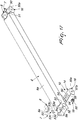
- the retention element 14 can be provided, as an alternative, by means of a plate-like body 50 which is fitted so that it can translate, with respect to said contrast bar 6, along a movement direction 100, which is substantially perpendicular to the axis of the engagement pin 8a.
- the plate-like body 50 lies conveniently on a plane that is substantially perpendicular to the axis of the seat 9a and engages slidingly, with its own mutually opposite longitudinal edges, a pair of guiding seats 52, which are extended along said movement direction 100 and are formed in the profiled element 6a of the contrast bar 6.
- the extraction of the plate-like body 50 from the guiding seats 52 is prevented by at least one abutment element 53, which also allows to delimit the stroke of the plate-like body 50 along the movement direction 100.
- the abutment element 53 is fixed to the contrast bar 6 and engages a respective elongated opening 54, which is formed in the plate-like body and is extended substantially parallel to the guiding seats 52.
- each abutment element 53 can be optionally provided, as in the embodiment of Figures 12-16 , by a screw 53a, which is screwed into a complementarily threaded hole 53b provided in the profiled element 6a of the contrast body 6 or, as in the variation of Figures 17 and 18 , by pins 53c, which are engaged by interference in respective interlocking holes 53d, which are again formed in the profiled element 6a of the contrast body 6.
- the plate-like body 50 has a folded end 50a which in practice forms the button 16 for the actuation in motion of the plate-like body 50.
- the elastic means 15 are conveniently provided by a return spring 55, which is advantageously retained in a position that is interposed between the contrast bar 6 and the folded end 50a of the plate-like body 50 by an abutment seat 56, which is formed in the contrast bar 6, and an engagement protrusion 57, which is provided on the folded end 50a of the plate-like body 50 by means of an indentation 57a.
- the through slot 58 has at least two communicating portions, respectively an engagement portion 58a and an insertion portion 58b, which are arranged in succession along the longitudinal extension of the through slot 58. More particularly, the insertion portion 58b has, transversely to the longitudinal extension of the through slot 58, a larger space occupation than the engagement portion 58a.
- the engagement pin 8a is capable of passing through the insertion portion 58b but not through the engagement portion 58a of the through slot 51.
- the plate-like body 50 is in a locking position, in which it is capable of preventing the disengagement of the engagement pin 8a from the seat 9a, while when the insertion portion 58b is located at the seat 9a the plate-like body 50 is in a release position, in which it allows the insertion and exit of the engagement pin 8a with respect to the seat 9a.
- the return spring 55 acts in the sense of keeping the plate-like body 50 in the locking position, so that the transition of the plate-like body 50 from the locking position to the release position can occur as a consequence of the application, on the part of the user, on the folded end 50a of the plate-like body 50, of a thrust that is capable of overcoming the force applied by the return spring 55.
- the engagement pin 8a can be engaged with the engagement portion 58a of the through slot 51, following the crossing, on the part of the engagement pin 8a, of the insertion portion 58b, which is arranged beforehand by the user at the seat 9a, by virtue of a movement of the plate-like body 50 in the release position, and following the insertion of the engagement pin 8a in the seat 9a, with subsequent translation of the plate-like body 50, along its movement direction, from the release position to the locking position, due to the elastic return of the return spring 54, so to achieve the placement of the engagement portion 58a at the seat 9a and in engagement with the portion of the engagement pin 8a that is affected by the groove 17.
Landscapes
- Engineering & Computer Science (AREA)
- Mechanical Engineering (AREA)
- Chemical & Material Sciences (AREA)
- Dispersion Chemistry (AREA)
- Vacuum Packaging (AREA)
- Closures For Containers (AREA)
Claims (10)
- Machine (1) destinée à emballer des produits alimentaires dans des sacs sous vide, comportant une structure de base (2) avec une chambre à vide (3) formée dans celle-ci qui peut être fermée au moyen d'un couvercle (4) et est conçue pour recevoir un sac pour l'emballage sous vide de produits alimentaires, des moyens étant prévus pour sceller ledit sac qui comportent une barre de thermoscellage (5), associée à ladite structure de base (2), et une barre en opposition (6), associée audit couvercle (4), caractérisée en ce que ladite barre en opposition (6) est associée audit couvercle (4) de manière détachable au moyen d'au moins un dispositif de couplage/découplage rapide (7), et en ce que ledit au moins un dispositif de couplage/découplage rapide (7) comporte des moyens d'appariement mâle (9) dans lesquels peuvent s'engager des moyens d'appariement femelle (9), des moyens (10) pour retenir lesdits moyens d'appariement mâle (8) engagés dans lesdits moyens d'appariement femelle (9), et des moyens d'actionnement (11) qui peuvent être activés par l'utilisateur pour désactiver lesdits moyens de retenue (10) et permettre le désengagement desdits moyens d'appariement mâle (8) desdits moyens d'appariement femelle (9).
- Machine selon la revendication 1, caractérisée en ce que lesdits moyens d'appariement femelle (9) comportent un logement (9a) qui est formé sur ladite barre en opposition (6), lesdits moyens d'appariement mâle (8) comportant un ergot d'engagement (8a), qui est relié audit couvercle (4) et peut s'engager dans ledit logement (9a) de manière détachable.
- Machine selon la revendication 2, caractérisée en ce que lesdits moyens de retenue (10) comportent, sur ledit logement (9a), un élément de retenue (14), qui est poussé par des moyens élastiques (15) afin de retenir ledit ergot d'engagement (8a) dans ledit logement (9a) et peut se déplacer en opposition auxdits moyens élastiques (15) afin de permettre l'insertion dudit ergot d'engagement (8a) dans ledit logement (9a), lesdits moyens d'actionnement comportant un bouton (16) qui est adapté pour actionner le mouvement dudit élément de retenue (14) en désengagement dudit ergot d'engagement (8a) afin de permettre le désengagement dudit ergot d'engagement (8a) dudit logement (9a).
- Machine selon la revendication 3, caractérisée en ce que ledit ergot d'engagement (8a) a, sur sa surface latérale, une rainure (17) dans laquelle peut s'engager ledit élément de retenue (14).
- Machine selon la revendication 3, caractérisée en ce que ledit élément de retenue (14) comporte un corps de levier (18) qui peut tourner par rapport à ladite barre en opposition (6), ledit bouton (16) comportant une extrémité (18a) pour l'actionnement dudit corps de levier (18).
- Machine selon la revendication 5, caractérisée en ce que ledit corps de levier (18) a une ouverture traversante (20) et peut être déplacé entre une position de blocage, dans laquelle il affecte, avec au moins une de ses parties, ledit logement (9a), et une position de libération, dans laquelle ladite ouverture traversante (20) est sensiblement alignée avec ledit logement (9a).
- Machine selon la revendication 3, caractérisée en ce que ledit élément de retenue (14) comporte un corps analogue à une plaque (50) qui est monté de sorte qu'il peut se déplacer en translation, par rapport à ladite barre en opposition (6), le long d'une direction de mouvement (100) qui est sensiblement perpendiculaire à l'axe dudit ergot d'engagement (8a).
- Machine selon la revendication 7, caractérisée en ce qu'une fente traversante (51) est formée dans ledit corps analogue à une plaque (50), s'étend de manière sensiblement parallèle à ladite direction de mouvement (100) et a au moins deux parties en communication, respectivement une partie d'engagement (58a) et une partie d'insertion (58b), qui sont agencées successivement le long de l'extension longitudinale de ladite fente traversante (51), ladite partie d'insertion (58b) ayant, transversalement à l'extension longitudinale de ladite fente traversante (51), une occupation d'espace plus grande que ladite partie d'engagement (58a), ladite partie d'engagement (58a) et ladite partie d'insertion (58b) pouvant être sélectivement agencées sur ledit logement (9a) au moyen d'une translation dudit corps analogue à une plaque (50) le long de ladite direction de mouvement (100), ledit ergot d'engagement (8a) étant adapté pour passer à travers ladite partie d'insertion (58b) mais pas à travers ladite partie d'engagement (58a) de ladite fente traversante (51), ledit ergot d'engagement (8a) pouvant s'engager dans ladite partie d'engagement (58a) de ladite fente traversante (51) après le croisement de ladite partie d'insertion (58b), agencée sur ledit logement (9a), par ledit ergot d'engagement (8a) et après l'insertion dudit ergot d'engagement dans ledit logement (9a), avec une translation ultérieure dudit corps analogue à une plaque (50) le long de ladite direction de mouvement (100), afin d'amener ladite partie d'engagement (58a) sur ledit logement (9a) et en engagement dans la partie dudit ergot d'engagement (8a) qui est affectée par ladite rainure (17).
- Machine selon la revendication 2, caractérisée en ce que ledit ergot d'engagement (8a) est relié audit couvercle (4) du fait de l'interposition de moyens pour régler sa position axiale.
- Machine selon la revendication 1, caractérisée en ce qu'elle comporte une paire de dispositifs de couplage/découplage rapide (7) qui sont agencés aux extrémités de ladite barre en opposition (6).
Applications Claiming Priority (1)
| Application Number | Priority Date | Filing Date | Title |
|---|---|---|---|
| IT102018000003801A IT201800003801A1 (it) | 2018-03-21 | 2018-03-21 | Macchina confezionatrice di prodotti alimentari in sacchetti sottovuoto. |
Publications (2)
| Publication Number | Publication Date |
|---|---|
| EP3543153A1 EP3543153A1 (fr) | 2019-09-25 |
| EP3543153B1 true EP3543153B1 (fr) | 2021-04-07 |
Family
ID=62530482
Family Applications (1)
| Application Number | Title | Priority Date | Filing Date |
|---|---|---|---|
| EP19163839.4A Active EP3543153B1 (fr) | 2018-03-21 | 2019-03-19 | Machine a emballer sous vide des produits alimentaires dans des sacs |
Country Status (3)
| Country | Link |
|---|---|
| EP (1) | EP3543153B1 (fr) |
| ES (1) | ES2873965T3 (fr) |
| IT (1) | IT201800003801A1 (fr) |
Families Citing this family (1)
| Publication number | Priority date | Publication date | Assignee | Title |
|---|---|---|---|---|
| CN115973534B (zh) * | 2023-03-23 | 2023-05-30 | 山东瓦鲁智能科技股份有限公司 | 一种农产品包装用真空包装设备 |
Family Cites Families (3)
| Publication number | Priority date | Publication date | Assignee | Title |
|---|---|---|---|---|
| AU2001279192A1 (en) * | 2000-08-02 | 2002-02-13 | Koch Equipment Llc | Injection-molded vacuum packaging machine |
| US20140202115A1 (en) * | 2013-01-22 | 2014-07-24 | Sheng-Nan Kuo | Sealing Module of a Vacuum Packing Machine |
| US10513362B2 (en) * | 2015-03-20 | 2019-12-24 | Dyco, Inc. | Sealing jaws for bagging apparatus |
-
2018
- 2018-03-21 IT IT102018000003801A patent/IT201800003801A1/it unknown
-
2019
- 2019-03-19 ES ES19163839T patent/ES2873965T3/es active Active
- 2019-03-19 EP EP19163839.4A patent/EP3543153B1/fr active Active
Non-Patent Citations (1)
| Title |
|---|
| None * |
Also Published As
| Publication number | Publication date |
|---|---|
| EP3543153A1 (fr) | 2019-09-25 |
| IT201800003801A1 (it) | 2019-09-21 |
| ES2873965T3 (es) | 2021-11-04 |
Similar Documents
| Publication | Publication Date | Title |
|---|---|---|
| EP3009053B1 (fr) | Ensemble couvercle et récipient pour boire comprenant celui-ci | |
| EP1721553B1 (fr) | Ensemble d'infusion pour appareil de préparation de boissons | |
| KR101018018B1 (ko) | 회전식 락킹/언락킹 제어 장치를 구비한 압력 조리 기구 | |
| EP1938717B1 (fr) | Appareil de cuisson sous pression muni d'un verrou | |
| WO2017071654A1 (fr) | Couvercle auto-ouvrant et récipient le comprenant | |
| KR101243835B1 (ko) | 안전수단을 갖는 락요소에 의하여 밀폐되는 냄비. | |
| EP3543153B1 (fr) | Machine a emballer sous vide des produits alimentaires dans des sacs | |
| KR20190053900A (ko) | 뚜껑의 용이한 개폐를 위한 기구를 갖는 전열 압력 기기 | |
| EP2859821B1 (fr) | Dispositif de verrouillage et machine à café à capsule équipée de celui-ci | |
| US10612686B2 (en) | Safety faucet for hot water | |
| US3130881A (en) | Tea kettle with closure lid, handle, and pouring spout | |
| FR2796541A1 (fr) | Dispositif de fermeture/ouverture pour un autocuiseur a couvercle rentrant | |
| NO781115L (no) | Anordning til lett tillukning av plastposer | |
| CN111236774A (zh) | 烹饪电器及其锁止机构 | |
| KR101520176B1 (ko) | 음료 용기의 마개체 | |
| EP1295552B1 (fr) | Soupape de commande de pression | |
| KR101147113B1 (ko) | 조리용기용 분리형 손잡이 | |
| EP2096967B1 (fr) | Appareil de cuisson sous pression | |
| JP6279278B2 (ja) | 蓋部材及び容器 | |
| EP2904949B1 (fr) | Autocuiseur à trou d'homme à fermeture facilitée | |
| KR102139567B1 (ko) | 압력솥 뚜껑의 잠금장치 | |
| EP2124686B1 (fr) | Appareil de cuisson sous pression a effort d'ouverture / fermeture variable | |
| KR100406348B1 (ko) | 압력솥뚜껑 안전개폐장치 | |
| CN108338655B (zh) | 烹饪器具 | |
| KR960000233Y1 (ko) | 편수손잡이 압력밥솥의 안전개폐장치 |
Legal Events
| Date | Code | Title | Description |
|---|---|---|---|
| PUAI | Public reference made under article 153(3) epc to a published international application that has entered the european phase |
Free format text: ORIGINAL CODE: 0009012 |
|
| STAA | Information on the status of an ep patent application or granted ep patent |
Free format text: STATUS: THE APPLICATION HAS BEEN PUBLISHED |
|
| AK | Designated contracting states |
Kind code of ref document: A1 Designated state(s): AL AT BE BG CH CY CZ DE DK EE ES FI FR GB GR HR HU IE IS IT LI LT LU LV MC MK MT NL NO PL PT RO RS SE SI SK SM TR |
|
| AX | Request for extension of the european patent |
Extension state: BA ME |
|
| STAA | Information on the status of an ep patent application or granted ep patent |
Free format text: STATUS: REQUEST FOR EXAMINATION WAS MADE |
|
| 17P | Request for examination filed |
Effective date: 20191126 |
|
| RBV | Designated contracting states (corrected) |
Designated state(s): AL AT BE BG CH CY CZ DE DK EE ES FI FR GB GR HR HU IE IS IT LI LT LU LV MC MK MT NL NO PL PT RO RS SE SI SK SM TR |
|
| GRAP | Despatch of communication of intention to grant a patent |
Free format text: ORIGINAL CODE: EPIDOSNIGR1 |
|
| STAA | Information on the status of an ep patent application or granted ep patent |
Free format text: STATUS: GRANT OF PATENT IS INTENDED |
|
| RIC1 | Information provided on ipc code assigned before grant |
Ipc: B65B 31/02 20060101AFI20200923BHEP Ipc: B29C 65/02 20060101ALI20200923BHEP Ipc: B65B 51/14 20060101ALI20200923BHEP Ipc: B65B 59/04 20060101ALI20200923BHEP |
|
| INTG | Intention to grant announced |
Effective date: 20201026 |
|
| GRAS | Grant fee paid |
Free format text: ORIGINAL CODE: EPIDOSNIGR3 |
|
| GRAA | (expected) grant |
Free format text: ORIGINAL CODE: 0009210 |
|
| STAA | Information on the status of an ep patent application or granted ep patent |
Free format text: STATUS: THE PATENT HAS BEEN GRANTED |
|
| AK | Designated contracting states |
Kind code of ref document: B1 Designated state(s): AL AT BE BG CH CY CZ DE DK EE ES FI FR GB GR HR HU IE IS IT LI LT LU LV MC MK MT NL NO PL PT RO RS SE SI SK SM TR |
|
| REG | Reference to a national code |
Ref country code: GB Ref legal event code: FG4D |
|
| REG | Reference to a national code |
Ref country code: AT Ref legal event code: REF Ref document number: 1379404 Country of ref document: AT Kind code of ref document: T Effective date: 20210415 Ref country code: CH Ref legal event code: EP |
|
| REG | Reference to a national code |
Ref country code: DE Ref legal event code: R096 Ref document number: 602019003680 Country of ref document: DE |
|
| REG | Reference to a national code |
Ref country code: IE Ref legal event code: FG4D |
|
| REG | Reference to a national code |
Ref country code: LT Ref legal event code: MG9D |
|
| REG | Reference to a national code |
Ref country code: NL Ref legal event code: MP Effective date: 20210407 Ref country code: AT Ref legal event code: MK05 Ref document number: 1379404 Country of ref document: AT Kind code of ref document: T Effective date: 20210407 |
|
| PG25 | Lapsed in a contracting state [announced via postgrant information from national office to epo] |
Ref country code: NL Free format text: LAPSE BECAUSE OF FAILURE TO SUBMIT A TRANSLATION OF THE DESCRIPTION OR TO PAY THE FEE WITHIN THE PRESCRIBED TIME-LIMIT Effective date: 20210407 Ref country code: BG Free format text: LAPSE BECAUSE OF FAILURE TO SUBMIT A TRANSLATION OF THE DESCRIPTION OR TO PAY THE FEE WITHIN THE PRESCRIBED TIME-LIMIT Effective date: 20210707 Ref country code: AT Free format text: LAPSE BECAUSE OF FAILURE TO SUBMIT A TRANSLATION OF THE DESCRIPTION OR TO PAY THE FEE WITHIN THE PRESCRIBED TIME-LIMIT Effective date: 20210407 Ref country code: FI Free format text: LAPSE BECAUSE OF FAILURE TO SUBMIT A TRANSLATION OF THE DESCRIPTION OR TO PAY THE FEE WITHIN THE PRESCRIBED TIME-LIMIT Effective date: 20210407 Ref country code: HR Free format text: LAPSE BECAUSE OF FAILURE TO SUBMIT A TRANSLATION OF THE DESCRIPTION OR TO PAY THE FEE WITHIN THE PRESCRIBED TIME-LIMIT Effective date: 20210407 Ref country code: LT Free format text: LAPSE BECAUSE OF FAILURE TO SUBMIT A TRANSLATION OF THE DESCRIPTION OR TO PAY THE FEE WITHIN THE PRESCRIBED TIME-LIMIT Effective date: 20210407 |
|
| PG25 | Lapsed in a contracting state [announced via postgrant information from national office to epo] |
Ref country code: GR Free format text: LAPSE BECAUSE OF FAILURE TO SUBMIT A TRANSLATION OF THE DESCRIPTION OR TO PAY THE FEE WITHIN THE PRESCRIBED TIME-LIMIT Effective date: 20210708 Ref country code: IS Free format text: LAPSE BECAUSE OF FAILURE TO SUBMIT A TRANSLATION OF THE DESCRIPTION OR TO PAY THE FEE WITHIN THE PRESCRIBED TIME-LIMIT Effective date: 20210807 Ref country code: PL Free format text: LAPSE BECAUSE OF FAILURE TO SUBMIT A TRANSLATION OF THE DESCRIPTION OR TO PAY THE FEE WITHIN THE PRESCRIBED TIME-LIMIT Effective date: 20210407 Ref country code: LV Free format text: LAPSE BECAUSE OF FAILURE TO SUBMIT A TRANSLATION OF THE DESCRIPTION OR TO PAY THE FEE WITHIN THE PRESCRIBED TIME-LIMIT Effective date: 20210407 Ref country code: NO Free format text: LAPSE BECAUSE OF FAILURE TO SUBMIT A TRANSLATION OF THE DESCRIPTION OR TO PAY THE FEE WITHIN THE PRESCRIBED TIME-LIMIT Effective date: 20210707 Ref country code: SE Free format text: LAPSE BECAUSE OF FAILURE TO SUBMIT A TRANSLATION OF THE DESCRIPTION OR TO PAY THE FEE WITHIN THE PRESCRIBED TIME-LIMIT Effective date: 20210407 Ref country code: PT Free format text: LAPSE BECAUSE OF FAILURE TO SUBMIT A TRANSLATION OF THE DESCRIPTION OR TO PAY THE FEE WITHIN THE PRESCRIBED TIME-LIMIT Effective date: 20210809 Ref country code: RS Free format text: LAPSE BECAUSE OF FAILURE TO SUBMIT A TRANSLATION OF THE DESCRIPTION OR TO PAY THE FEE WITHIN THE PRESCRIBED TIME-LIMIT Effective date: 20210407 |
|
| REG | Reference to a national code |
Ref country code: DE Ref legal event code: R097 Ref document number: 602019003680 Country of ref document: DE |
|
| PG25 | Lapsed in a contracting state [announced via postgrant information from national office to epo] |
Ref country code: EE Free format text: LAPSE BECAUSE OF FAILURE TO SUBMIT A TRANSLATION OF THE DESCRIPTION OR TO PAY THE FEE WITHIN THE PRESCRIBED TIME-LIMIT Effective date: 20210407 Ref country code: SK Free format text: LAPSE BECAUSE OF FAILURE TO SUBMIT A TRANSLATION OF THE DESCRIPTION OR TO PAY THE FEE WITHIN THE PRESCRIBED TIME-LIMIT Effective date: 20210407 Ref country code: CZ Free format text: LAPSE BECAUSE OF FAILURE TO SUBMIT A TRANSLATION OF THE DESCRIPTION OR TO PAY THE FEE WITHIN THE PRESCRIBED TIME-LIMIT Effective date: 20210407 Ref country code: DK Free format text: LAPSE BECAUSE OF FAILURE TO SUBMIT A TRANSLATION OF THE DESCRIPTION OR TO PAY THE FEE WITHIN THE PRESCRIBED TIME-LIMIT Effective date: 20210407 Ref country code: SM Free format text: LAPSE BECAUSE OF FAILURE TO SUBMIT A TRANSLATION OF THE DESCRIPTION OR TO PAY THE FEE WITHIN THE PRESCRIBED TIME-LIMIT Effective date: 20210407 Ref country code: RO Free format text: LAPSE BECAUSE OF FAILURE TO SUBMIT A TRANSLATION OF THE DESCRIPTION OR TO PAY THE FEE WITHIN THE PRESCRIBED TIME-LIMIT Effective date: 20210407 |
|
| PLBE | No opposition filed within time limit |
Free format text: ORIGINAL CODE: 0009261 |
|
| STAA | Information on the status of an ep patent application or granted ep patent |
Free format text: STATUS: NO OPPOSITION FILED WITHIN TIME LIMIT |
|
| 26N | No opposition filed |
Effective date: 20220110 |
|
| PG25 | Lapsed in a contracting state [announced via postgrant information from national office to epo] |
Ref country code: IS Free format text: LAPSE BECAUSE OF FAILURE TO SUBMIT A TRANSLATION OF THE DESCRIPTION OR TO PAY THE FEE WITHIN THE PRESCRIBED TIME-LIMIT Effective date: 20210807 Ref country code: AL Free format text: LAPSE BECAUSE OF FAILURE TO SUBMIT A TRANSLATION OF THE DESCRIPTION OR TO PAY THE FEE WITHIN THE PRESCRIBED TIME-LIMIT Effective date: 20210407 |
|
| PG25 | Lapsed in a contracting state [announced via postgrant information from national office to epo] |
Ref country code: MC Free format text: LAPSE BECAUSE OF FAILURE TO SUBMIT A TRANSLATION OF THE DESCRIPTION OR TO PAY THE FEE WITHIN THE PRESCRIBED TIME-LIMIT Effective date: 20210407 |
|
| REG | Reference to a national code |
Ref country code: CH Ref legal event code: PL |
|
| REG | Reference to a national code |
Ref country code: BE Ref legal event code: MM Effective date: 20220331 |
|
| PG25 | Lapsed in a contracting state [announced via postgrant information from national office to epo] |
Ref country code: LU Free format text: LAPSE BECAUSE OF NON-PAYMENT OF DUE FEES Effective date: 20220319 Ref country code: LI Free format text: LAPSE BECAUSE OF NON-PAYMENT OF DUE FEES Effective date: 20220331 Ref country code: IE Free format text: LAPSE BECAUSE OF NON-PAYMENT OF DUE FEES Effective date: 20220319 Ref country code: CH Free format text: LAPSE BECAUSE OF NON-PAYMENT OF DUE FEES Effective date: 20220331 |
|
| PG25 | Lapsed in a contracting state [announced via postgrant information from national office to epo] |
Ref country code: BE Free format text: LAPSE BECAUSE OF NON-PAYMENT OF DUE FEES Effective date: 20220331 |
|
| P01 | Opt-out of the competence of the unified patent court (upc) registered |
Effective date: 20230529 |
|
| PG25 | Lapsed in a contracting state [announced via postgrant information from national office to epo] |
Ref country code: MK Free format text: LAPSE BECAUSE OF FAILURE TO SUBMIT A TRANSLATION OF THE DESCRIPTION OR TO PAY THE FEE WITHIN THE PRESCRIBED TIME-LIMIT Effective date: 20210407 Ref country code: CY Free format text: LAPSE BECAUSE OF FAILURE TO SUBMIT A TRANSLATION OF THE DESCRIPTION OR TO PAY THE FEE WITHIN THE PRESCRIBED TIME-LIMIT Effective date: 20210407 |
|
| PGFP | Annual fee paid to national office [announced via postgrant information from national office to epo] |
Ref country code: DE Payment date: 20240321 Year of fee payment: 6 Ref country code: GB Payment date: 20240318 Year of fee payment: 6 |
|
| PG25 | Lapsed in a contracting state [announced via postgrant information from national office to epo] |
Ref country code: HU Free format text: LAPSE BECAUSE OF FAILURE TO SUBMIT A TRANSLATION OF THE DESCRIPTION OR TO PAY THE FEE WITHIN THE PRESCRIBED TIME-LIMIT; INVALID AB INITIO Effective date: 20190319 |
|
| PGFP | Annual fee paid to national office [announced via postgrant information from national office to epo] |
Ref country code: IT Payment date: 20240320 Year of fee payment: 6 Ref country code: FR Payment date: 20240318 Year of fee payment: 6 |
|
| PG25 | Lapsed in a contracting state [announced via postgrant information from national office to epo] |
Ref country code: TR Free format text: LAPSE BECAUSE OF FAILURE TO SUBMIT A TRANSLATION OF THE DESCRIPTION OR TO PAY THE FEE WITHIN THE PRESCRIBED TIME-LIMIT Effective date: 20210407 |
|
| PGFP | Annual fee paid to national office [announced via postgrant information from national office to epo] |
Ref country code: ES Payment date: 20240411 Year of fee payment: 6 |
|
| PG25 | Lapsed in a contracting state [announced via postgrant information from national office to epo] |
Ref country code: MT Free format text: LAPSE BECAUSE OF FAILURE TO SUBMIT A TRANSLATION OF THE DESCRIPTION OR TO PAY THE FEE WITHIN THE PRESCRIBED TIME-LIMIT Effective date: 20210407 |