EP3543059A1 - Method for calculating the insertion of additional information for display on a display unit, device for carrying out the method, motor vehicle and computer program - Google Patents
Method for calculating the insertion of additional information for display on a display unit, device for carrying out the method, motor vehicle and computer program Download PDFInfo
- Publication number
- EP3543059A1 EP3543059A1 EP19157312.0A EP19157312A EP3543059A1 EP 3543059 A1 EP3543059 A1 EP 3543059A1 EP 19157312 A EP19157312 A EP 19157312A EP 3543059 A1 EP3543059 A1 EP 3543059A1
- Authority
- EP
- European Patent Office
- Prior art keywords
- vehicle
- calculated
- display
- preceding vehicle
- distance
- Prior art date
- Legal status (The legal status is an assumption and is not a legal conclusion. Google has not performed a legal analysis and makes no representation as to the accuracy of the status listed.)
- Granted
Links
- 238000000034 method Methods 0.000 title claims abstract description 41
- 238000003780 insertion Methods 0.000 title claims abstract description 12
- 230000037431 insertion Effects 0.000 title claims abstract description 12
- 238000004590 computer program Methods 0.000 title claims description 7
- 230000003190 augmentative effect Effects 0.000 claims abstract description 10
- 239000011521 glass Substances 0.000 claims abstract description 9
- 230000000694 effects Effects 0.000 claims description 35
- 238000013459 approach Methods 0.000 claims description 15
- 230000033228 biological regulation Effects 0.000 claims description 14
- 238000004364 calculation method Methods 0.000 claims description 10
- 238000001514 detection method Methods 0.000 claims description 9
- 230000004438 eyesight Effects 0.000 claims description 8
- 230000001105 regulatory effect Effects 0.000 claims description 7
- 238000012545 processing Methods 0.000 claims description 4
- 230000033001 locomotion Effects 0.000 claims description 3
- 230000006870 function Effects 0.000 description 14
- 238000004891 communication Methods 0.000 description 10
- 230000008901 benefit Effects 0.000 description 8
- 239000010432 diamond Substances 0.000 description 7
- 229910003460 diamond Inorganic materials 0.000 description 6
- 238000005516 engineering process Methods 0.000 description 6
- 230000008569 process Effects 0.000 description 6
- 238000010586 diagram Methods 0.000 description 4
- 230000008859 change Effects 0.000 description 3
- 230000007774 longterm Effects 0.000 description 3
- 238000012544 monitoring process Methods 0.000 description 3
- 230000007935 neutral effect Effects 0.000 description 3
- 230000008447 perception Effects 0.000 description 3
- 238000011161 development Methods 0.000 description 2
- 230000018109 developmental process Effects 0.000 description 2
- 238000000605 extraction Methods 0.000 description 2
- 230000006872 improvement Effects 0.000 description 2
- 239000007937 lozenge Substances 0.000 description 2
- 230000001404 mediated effect Effects 0.000 description 2
- 238000010295 mobile communication Methods 0.000 description 2
- 230000035515 penetration Effects 0.000 description 2
- 230000011664 signaling Effects 0.000 description 2
- 238000012549 training Methods 0.000 description 2
- 230000007704 transition Effects 0.000 description 2
- 238000012800 visualization Methods 0.000 description 2
- 240000006829 Ficus sundaica Species 0.000 description 1
- 230000001133 acceleration Effects 0.000 description 1
- 230000004308 accommodation Effects 0.000 description 1
- 230000003044 adaptive effect Effects 0.000 description 1
- 238000004378 air conditioning Methods 0.000 description 1
- 238000003491 array Methods 0.000 description 1
- 230000006399 behavior Effects 0.000 description 1
- 230000005540 biological transmission Effects 0.000 description 1
- 230000001149 cognitive effect Effects 0.000 description 1
- 230000001427 coherent effect Effects 0.000 description 1
- 238000012790 confirmation Methods 0.000 description 1
- 238000010276 construction Methods 0.000 description 1
- 230000001276 controlling effect Effects 0.000 description 1
- 230000001419 dependent effect Effects 0.000 description 1
- 238000013461 design Methods 0.000 description 1
- 238000006073 displacement reaction Methods 0.000 description 1
- 238000011156 evaluation Methods 0.000 description 1
- 238000007667 floating Methods 0.000 description 1
- 239000012530 fluid Substances 0.000 description 1
- 238000009472 formulation Methods 0.000 description 1
- 230000003993 interaction Effects 0.000 description 1
- 230000000873 masking effect Effects 0.000 description 1
- 239000000203 mixture Substances 0.000 description 1
- 238000012986 modification Methods 0.000 description 1
- 230000004048 modification Effects 0.000 description 1
- 239000013307 optical fiber Substances 0.000 description 1
- 230000008520 organization Effects 0.000 description 1
- 230000009467 reduction Effects 0.000 description 1
- 238000011160 research Methods 0.000 description 1
- 230000004044 response Effects 0.000 description 1
- 239000003826 tablet Substances 0.000 description 1
- 101150060058 tag-335 gene Proteins 0.000 description 1
Images


Classifications
-
- G—PHYSICS
- G06—COMPUTING; CALCULATING OR COUNTING
- G06V—IMAGE OR VIDEO RECOGNITION OR UNDERSTANDING
- G06V20/00—Scenes; Scene-specific elements
- G06V20/50—Context or environment of the image
- G06V20/56—Context or environment of the image exterior to a vehicle by using sensors mounted on the vehicle
- G06V20/58—Recognition of moving objects or obstacles, e.g. vehicles or pedestrians; Recognition of traffic objects, e.g. traffic signs, traffic lights or roads
-
- B—PERFORMING OPERATIONS; TRANSPORTING
- B60—VEHICLES IN GENERAL
- B60W—CONJOINT CONTROL OF VEHICLE SUB-UNITS OF DIFFERENT TYPE OR DIFFERENT FUNCTION; CONTROL SYSTEMS SPECIALLY ADAPTED FOR HYBRID VEHICLES; ROAD VEHICLE DRIVE CONTROL SYSTEMS FOR PURPOSES NOT RELATED TO THE CONTROL OF A PARTICULAR SUB-UNIT
- B60W30/00—Purposes of road vehicle drive control systems not related to the control of a particular sub-unit, e.g. of systems using conjoint control of vehicle sub-units, or advanced driver assistance systems for ensuring comfort, stability and safety or drive control systems for propelling or retarding the vehicle
- B60W30/08—Active safety systems predicting or avoiding probable or impending collision or attempting to minimise its consequences
-
- B—PERFORMING OPERATIONS; TRANSPORTING
- B60—VEHICLES IN GENERAL
- B60K—ARRANGEMENT OR MOUNTING OF PROPULSION UNITS OR OF TRANSMISSIONS IN VEHICLES; ARRANGEMENT OR MOUNTING OF PLURAL DIVERSE PRIME-MOVERS IN VEHICLES; AUXILIARY DRIVES FOR VEHICLES; INSTRUMENTATION OR DASHBOARDS FOR VEHICLES; ARRANGEMENTS IN CONNECTION WITH COOLING, AIR INTAKE, GAS EXHAUST OR FUEL SUPPLY OF PROPULSION UNITS IN VEHICLES
- B60K35/00—Arrangement of adaptations of instruments
-
- B60K35/23—
-
- B60K35/28—
-
- B60K35/29—
-
- B—PERFORMING OPERATIONS; TRANSPORTING
- B60—VEHICLES IN GENERAL
- B60W—CONJOINT CONTROL OF VEHICLE SUB-UNITS OF DIFFERENT TYPE OR DIFFERENT FUNCTION; CONTROL SYSTEMS SPECIALLY ADAPTED FOR HYBRID VEHICLES; ROAD VEHICLE DRIVE CONTROL SYSTEMS FOR PURPOSES NOT RELATED TO THE CONTROL OF A PARTICULAR SUB-UNIT
- B60W30/00—Purposes of road vehicle drive control systems not related to the control of a particular sub-unit, e.g. of systems using conjoint control of vehicle sub-units, or advanced driver assistance systems for ensuring comfort, stability and safety or drive control systems for propelling or retarding the vehicle
- B60W30/14—Adaptive cruise control
-
- B—PERFORMING OPERATIONS; TRANSPORTING
- B60—VEHICLES IN GENERAL
- B60W—CONJOINT CONTROL OF VEHICLE SUB-UNITS OF DIFFERENT TYPE OR DIFFERENT FUNCTION; CONTROL SYSTEMS SPECIALLY ADAPTED FOR HYBRID VEHICLES; ROAD VEHICLE DRIVE CONTROL SYSTEMS FOR PURPOSES NOT RELATED TO THE CONTROL OF A PARTICULAR SUB-UNIT
- B60W50/00—Details of control systems for road vehicle drive control not related to the control of a particular sub-unit, e.g. process diagnostic or vehicle driver interfaces
- B60W50/08—Interaction between the driver and the control system
- B60W50/14—Means for informing the driver, warning the driver or prompting a driver intervention
-
- G—PHYSICS
- G01—MEASURING; TESTING
- G01C—MEASURING DISTANCES, LEVELS OR BEARINGS; SURVEYING; NAVIGATION; GYROSCOPIC INSTRUMENTS; PHOTOGRAMMETRY OR VIDEOGRAMMETRY
- G01C21/00—Navigation; Navigational instruments not provided for in groups G01C1/00 - G01C19/00
- G01C21/26—Navigation; Navigational instruments not provided for in groups G01C1/00 - G01C19/00 specially adapted for navigation in a road network
- G01C21/34—Route searching; Route guidance
- G01C21/36—Input/output arrangements for on-board computers
- G01C21/3626—Details of the output of route guidance instructions
- G01C21/365—Guidance using head up displays or projectors, e.g. virtual vehicles or arrows projected on the windscreen or on the road itself
-
- G—PHYSICS
- G02—OPTICS
- G02B—OPTICAL ELEMENTS, SYSTEMS OR APPARATUS
- G02B27/00—Optical systems or apparatus not provided for by any of the groups G02B1/00 - G02B26/00, G02B30/00
- G02B27/01—Head-up displays
-
- G—PHYSICS
- G02—OPTICS
- G02B—OPTICAL ELEMENTS, SYSTEMS OR APPARATUS
- G02B27/00—Optical systems or apparatus not provided for by any of the groups G02B1/00 - G02B26/00, G02B30/00
- G02B27/01—Head-up displays
- G02B27/0101—Head-up displays characterised by optical features
-
- G—PHYSICS
- G06—COMPUTING; CALCULATING OR COUNTING
- G06T—IMAGE DATA PROCESSING OR GENERATION, IN GENERAL
- G06T19/00—Manipulating 3D models or images for computer graphics
- G06T19/006—Mixed reality
-
- G—PHYSICS
- G06—COMPUTING; CALCULATING OR COUNTING
- G06V—IMAGE OR VIDEO RECOGNITION OR UNDERSTANDING
- G06V20/00—Scenes; Scene-specific elements
- G06V20/20—Scenes; Scene-specific elements in augmented reality scenes
-
- G—PHYSICS
- G08—SIGNALLING
- G08G—TRAFFIC CONTROL SYSTEMS
- G08G1/00—Traffic control systems for road vehicles
- G08G1/16—Anti-collision systems
-
- B60K2360/177—
-
- B60K2360/178—
-
- B60K2360/179—
-
- B60K2360/191—
-
- B60K2360/334—
-
- B—PERFORMING OPERATIONS; TRANSPORTING
- B60—VEHICLES IN GENERAL
- B60W—CONJOINT CONTROL OF VEHICLE SUB-UNITS OF DIFFERENT TYPE OR DIFFERENT FUNCTION; CONTROL SYSTEMS SPECIALLY ADAPTED FOR HYBRID VEHICLES; ROAD VEHICLE DRIVE CONTROL SYSTEMS FOR PURPOSES NOT RELATED TO THE CONTROL OF A PARTICULAR SUB-UNIT
- B60W50/00—Details of control systems for road vehicle drive control not related to the control of a particular sub-unit, e.g. process diagnostic or vehicle driver interfaces
- B60W50/08—Interaction between the driver and the control system
- B60W50/14—Means for informing the driver, warning the driver or prompting a driver intervention
- B60W2050/146—Display means
-
- G—PHYSICS
- G02—OPTICS
- G02B—OPTICAL ELEMENTS, SYSTEMS OR APPARATUS
- G02B27/00—Optical systems or apparatus not provided for by any of the groups G02B1/00 - G02B26/00, G02B30/00
- G02B27/01—Head-up displays
- G02B27/0101—Head-up displays characterised by optical features
- G02B2027/014—Head-up displays characterised by optical features comprising information/image processing systems
-
- G—PHYSICS
- G02—OPTICS
- G02B—OPTICAL ELEMENTS, SYSTEMS OR APPARATUS
- G02B27/00—Optical systems or apparatus not provided for by any of the groups G02B1/00 - G02B26/00, G02B30/00
- G02B27/01—Head-up displays
- G02B27/0101—Head-up displays characterised by optical features
- G02B2027/0141—Head-up displays characterised by optical features characterised by the informative content of the display
-
- G—PHYSICS
- G02—OPTICS
- G02B—OPTICAL ELEMENTS, SYSTEMS OR APPARATUS
- G02B27/00—Optical systems or apparatus not provided for by any of the groups G02B1/00 - G02B26/00, G02B30/00
- G02B27/01—Head-up displays
- G02B27/0179—Display position adjusting means not related to the information to be displayed
- G02B2027/0185—Displaying image at variable distance
Definitions
- the proposal concerns the technical field of driver information systems, also known as infotainment systems. Such systems are used primarily in vehicles. But there is also the possibility of using the invention in pedestrians, cyclists, etc. with data glasses.
- the proposal further relates to a correspondingly designed device for carrying out the method and to a motor vehicle and a computer program.
- HUD Head-Up Display
- LTE V2X Long Term Evolution
- WLAN p wireless technology based systems for direct vehicle communication available, in particular the system according to WLAN p.
- a future vision in the automotive industry is to be able to record the windscreen of one's own vehicle with virtual elements, in order to offer the driver some advantages.
- the so-called "augmented reality” technology (AR) is used. Less familiar is the corresponding German-language term of "augmented reality”.
- the real environment is enriched with virtual elements. This has the advantage that due to the positionally accurate location of the virtual elements in the real environment, a lesser cognitive effort on the part of the driver is achieved, since no interpretation of an abstracting graphic must be made, but an intuitive understanding in the sense of normal perception habits can take place. With regard to automatic driving, an added value can also be generated.
- HUD Head-Up Displays
- the "image" projected by the HUD is composed as follows: it is less a virtual display, but rather a kind of "keyhole” in the virtual world.
- the virtual environment is theoretically placed over the real world and contains the virtual objects that support and inform the driver while driving.
- the limited display area of the HUD has the consequence that a section of it can be seen. So you look through the display area of the HUD on the section of the virtual world. Since this virtual environment complements the real environment, one speaks in this case of a "mixed reality".
- a method for marking a relevant point for a driver of a vehicle is known.
- the position of a relevant point in an apron of the vehicle is determined. This point is highlighted in a step of the method with a mark contact analog.
- the display mode of the marking is selected depending on the distance between the vehicle and the position of the relevant point.
- a device and a method for a vehicle which is designed for automatic longitudinal control.
- the following steps are performed: detecting a leading vehicle, wherein the leading vehicle is a vehicle running in front of the vehicle. Determining a current one of at least two states describing a current response of the vehicle to the leading vehicle. Representing the current state distinguishable from other states in animated form on a display.
- a method for providing a driver assistance system with automatic longitudinal regulation for a vehicle in which the preceding route section is visualized on a display surface, wherein at least one graphic object, which is assigned to a function of the automatic longitudinal control, is displayed in the visualized route section.
- the method for providing a driver assistance system with automatic longitudinal regulation is characterized in that a video image sequence is recorded on the preceding route segment and reproduced in real time on the display surface, and the at least one graphic object is superimposed on the video image sequence.
- the superimposed representation of a graphic object for vehicle longitudinal control with a video image sequence of the preceding route section in real time supports the driver in a holistic acquisition of the current driving situation.
- a method for displaying distance information on a display device of a vehicle is known.
- the process is remarkable characterized in that with camera a real image of the lane in front of the vehicle is recorded, and in dependence on at least one vehicle dynamic size of the vehicle, a safety distance to the vehicle in front is determined.
- the real image is extended by a virtual image portion in the form of a crossbar, which indicates the safety distance in the correct position to the vehicle in front.
- AR augmented reality
- classic navigation displays in conventional HUDs typically display schematics (for example, a right-sided arrow indicating that you want to turn right at the next opportunity
- AR displays are much more effective Environment, "extremely fast and intuitive interpretations are possible for the user, but the approaches known so far also present various problems for which no solutions are known at the present time.
- the invention sets itself the task of finding such an approach.
- This object is achieved by a method for calculating a display of additional information for a display on a display unit, in particular a head-up display (HUD) of a vehicle or a data glasses according to claim 1, an apparatus for performing the method according to claim 8 and a motor vehicle according to Claim 11 and a computer program according to claim 12.
- the insertion of additional information serves the purpose of assisting the driver in the longitudinal guidance of the vehicle.
- the solution according to the invention is based on calculating the display of the additional information in the manner of the augmented reality in accordance with "augmented reality" contact analogous to a vehicle in front. For this, the position of the vehicle in front is recorded.
- the method is characterized in that, when approaching the vehicle in front, an animation graphic is calculated in such a way that, starting from the observer vehicle, the animation graphics are optionally displayed periodically repeating sections by means of a display unit. This alerts the driver that a driver assistance function has detected a preceding vehicle and initiates a control function with respect to the preceding vehicle.
- an AR overlay is calculated such that at least one object identification mark is set at the end of the preceding vehicle in contact-analogous to the vehicle ahead. This provides the driver of the vehicle with an indication that the longitudinal guidance system has been set up and that it has recognized a preceding vehicle and is now operating relative to it.
- the AR overlay is calculated such that two object identification marks are set, wherein an object identification mark is calculated such that it marks the end of the area on the floor behind the vehicle and the other object identification mark marks the rear of the preceding vehicle.
- This procedure should make the driver understand the correct object perception and produce a transparency of the technical processes necessary for the confidence training.
- This variant should exploit the advantage that the mark is not in the vertical axis on the vehicle, but discreet on the ground. On the other hand, positioning errors are less noticeable (if the object tag is not exactly in the middle of the vehicle).
- the mark on the floor can be better accessed or manipulated by any animation of the animated graphics lying on the floor. An example is the displacement of the object tag.
- a control activity flag is calculated, which is calculated so that it approaches the vehicle ahead as an arrow towards the vehicle in front is displayed between the observer vehicle and the vehicle ahead, and at the distance from the vehicle in front as an arrow away from the vehicle in front between the observer vehicle and the vehicle ahead. This measure provides information about the control activity of the driving function.
- control activity flag is calculated to approach the preceding vehicle as it approaches the preceding vehicle, and when the target distance or speed is reached, the control activity flag is calculated to match the end of the animation graphic. reached at the position of the vehicle in front. The calculation then takes place in such a way that the control activity mark is merged with the object identification mark, wherein at least one side part of the control activity mark attaches contact-analogously next to the object identification mark.
- the regulation activity mark is calculated in such a way that it indicates the regulation activity of the longitudinal guidance system. At least three different states are distinguished, with an arrow pointing in the direction of travel is formed when the target speed of the longitudinal guide system is even greater than the instantaneous speed of the observer vehicle or the distance to the vehicle in front is still greater than the desired distance, with a backward arrow formed when the target speed of the cruise control system is less than the instantaneous speed of the observer vehicle, or the distance to the vehicle in front is still smaller than the target distance, and wherein the sides of the regulatory activity flag are positioned to form a line-like control engage mark when the actual Speed coincides with the target speed of the cruise control system or the distance coincides with the desired distance.
- This solution offers the driver a lot of information with only one AR overlay.
- the type of control activity flag indicates whether approach or departure to the vehicle in front is taking place. Also, the neutral phase, in which the vehicle in front is followed, as in the procession is so mediated. With this symbolism, the driver is informed that the vehicle from now on will keep the distance to the vehicle in front constant.
- the positioning of the regulation activity mark between the vehicle in front and the observer vehicle provides information about compliance with the nominal distance.
- the animation graphic is calculated in raster form.
- the grid consists of a plurality of raster elements.
- the raster form offers little obstruction of the environment and at the same time sufficient fault tolerance that the human perceptive apparatus can effortlessly understand the individual display elements as a coherent reference due to the evolutionary biological prerequisites. Particularly important here are to avoid unwanted masking effects that can occur with AR displays. This is achieved on the one hand by using the grid shape and on the other hand by calculation in such a way that the grid extends only to the vehicle in front. This bypasses the problem of "penetration" in AR overlays.
- “Penetration” is understood to mean display cases in which an AR display is displayed (e.g., a navigation path), but from the viewpoint of the user, "pass through” objects in front of the vehicle. These effects occur, among other things, when another vehicle drives in front of its own.
- the display unit of the device is designed as a head-up display.
- a data goggles or a monitor can be used in the device as a display unit, on which a camera image is displayed, in which the animation graphics is displayed.
- the device according to the invention can be used in a motor vehicle.
- the invention is preferably realized so that the display unit is permanently installed in the vehicle, e.g. in the form of a head-up display. Nevertheless, a possible form of realization would also be possible with the aid of data glasses, if the use of data glasses by the driver would be permitted in the future.
- the use on a mobile device such as a smartphone or tablet computer would be considered.
- the invention can also be advantageously used if the display unit corresponds to data glasses. Then the method according to the invention can be used even by pedestrians, cyclists, bikers, etc.
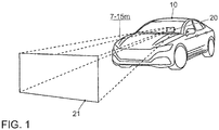
- Fig. 1 illustrates the basic operation of a head-up display.
- the head-up display 20 is mounted in the vehicle 10 below / behind the instrument cluster in the dashboard area.
- additional information is displayed in the driver's field of vision.
- This additional information appears as if it were projected onto a projection surface 21 at a distance of 7 - 15 m in front of the vehicle 10.
- the additional information displayed creates a kind of virtual environment.
- the virtual environment is theoretically placed over the real world and contains the virtual objects that support and inform the driver while driving. However, it is only projected onto a part of the windshield, so that the additional information can not be arbitrarily arranged in the field of vision of the driver.
- Fig. 2 shows the cockpit of the vehicle 10. Shown is a passenger car. As a vehicle 10, however, any other vehicles would also be considered. Examples of other vehicles are: buses, commercial vehicles, especially trucks trucks, agricultural machinery, construction machinery, rail vehicles, etc. The use of the invention would be generally in land vehicles, rail vehicles, watercraft and aircraft possible.
- the cockpit three display units of an infotainment system are shown. It is the head-up display 20 and a touch-sensitive screen 30 which is mounted in the center console.
- the center console When driving, the center console is not in the driver's field of vision. Therefore, the additional information is not displayed on the display unit 30 while driving.
- the touch-sensitive screen 30 serves, in particular, to operate functions of the vehicle 10.
- a radio for example, a radio, a navigation system, a playback of stored music pieces and / or an air-conditioning system, other electronic devices or other comfort functions or applications of the vehicle 10 can be controlled.
- infotainment system An infotainment system referred to in motor vehicles, especially cars, the merger of car radio, navigation system, speakerphone, driver assistance systems and other functions in a central control unit.
- infotainment is a portmanteau word composed of the words Information and entertainment (entertainment).
- touch screen 30 To operate the infotainment system mainly the touch-sensitive screen 30 ("touch screen”) is used, this screen 30 can be well viewed and operated in particular by a driver of the vehicle 10, but also by a passenger of the vehicle 10.
- mechanical operating elements for example keys, rotary encoders or combinations thereof, such as, for example, a push-dial regulator, can be arranged in an input unit 50.
- This unit is not shown separately, but is considered part of the input unit 50.
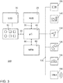
- Fig. 3 schematically shows a block diagram of the infotainment system 200 and, by way of example, some subsystems or applications of the infotainment system.
- the operation device includes the touch-sensitive display unit 30, a calculator 40, an input unit 50, and a memory 60.
- the display unit 30 includes both a display area for displaying variable graphic information and a user interface (touch-sensitive layer) for inputting commands through the display area User.
- the display unit 30 is connected to the computing device 40 via a data line 70.
- the data line can be designed according to the LVDS standard, corresponding to Low Voltage Differential Signaling.
- the display unit 30 receives control data for driving the display surface of the touch screen 30 from the computing device 40.
- Control data of the input commands are also transmitted from the touch screen 30 to the computing device 40 via the data line 70.
- Reference numeral 50 denotes the input unit. It includes the already mentioned control elements such as buttons, knobs, sliders, or rotary pushbuttons, with the help of which the operator can make inputs via the menu. Input is generally understood as selecting a selected menu item, as well as changing a parameter, turning a function on and off, and so on.
- the memory device 60 is connected to the computing device 40 via a data line 80.
- a pictogram directory and / or symbol directory is stored with the pictograms and / or symbols for the possible overlays of additional information.
- the points / symbols can be stored, which serve as the basis for the calculation of the raster overlay.
- the other parts of the infotainment system camera 150, radio 140, navigation device 130, telephone 120 and instrument cluster 110 are connected via the data bus 100 with the device for operating the infotainment system.
- data bus 100 is the high-speed variant of the CAN bus according to ISO standard 11898-2 into consideration.
- Ethernet-based bus system such as BroadR-Reach in question.
- Bus systems in which the data is transmitted via optical fibers can also be used. Examples are the MOST Bus (Media Oriented System Transport) or the D2B Bus (Domestic Digital Bus).
- the camera 150 can be designed as a conventional video camera. In this case, it will record 25 frames / s, which is equivalent to 50 fields / s in the interlace recording mode.
- the vehicle 10 is equipped with a communications module 160.
- This module is often referred to as an on-board unit. It can be used for mobile communication, e.g. according to LTE standard, according to Long Term Evolution. It can also be designed for WLAN communication, according to wireless LAN, whether for communication with in-vehicle devices or for vehicle-to-vehicle communication, etc.
- the basis of the display according to the invention of the longitudinal guidance function of the vehicle 10 on the HUD 20 is the display of a virtual grid which is displayed at a distance above the actual road or without distance to the road.
- the road is located as a real road course in the field of vision of the driver.
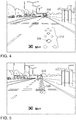
- the AR insertion by means of the HUD 20 is done as in Fig. 4 shown.
- the grid is projected to be on the road or "floating in space” at a distance from the road. It is shown that a grid is displayed along the roadway course. This extends to the preceding vehicle.
- Fig. 4 is shown that at the time shown only the first portion 310 of the grid is displayed.
- the second portion 320 of the grid is then faded in at a second time, s. Fig.
- the grid 22 could be divided into further sections that are displayed one after the other. This would make a more fluid movement of the beacon visible.
- a driver assistance system for longitudinal guidance of the vehicle 10 is used.
- Examples of such assistance systems are an automatic distance control ACC, corresponding to Adaptive Cruise Control and a cruise control system GRA, corresponding cruise control system.
- the invention would also be used in the same way, if the vehicle 10 would be controlled fully automatically.
- the following describes what steps are taken when the vehicle 10 with the longitudinal guidance system activated, here an ACC system, approaches the preceding vehicle 300, detects it and adapts its speed to the preceding vehicle 300. This is done so that a previously entered safety distance is maintained.
- the longitudinal guide system has already left the set-up mode and has switched to a control mode.
- the setup mode was visualized using the beacon display.
- the change from the device mode to the control mode is visualized as follows.
- the beacon display is exited and instead an AR overlay is calculated for the display of an object tag.
- even two object recognition marks 330 and 335 are calculated.
- the detection flag 330 becomes so calculates that it is displayed at the rear of the preceding vehicle 300 and marks the rear of the preceding vehicle 300.
- the driver is thereby signaled relative to which vehicle the longitudinal guidance system regulates the distance and / or the speed.
- the second detection mark 335 is set at the end of the previously displayed grid.
- both dog tags 330, 335 are diamond symbols. This procedure should make the driver understand the correct object perception and produce a transparency of the technical processes necessary for the confidence training.
- a second AR fade is calculated for the display of a control activity flag 340, which is intended to provide information about the control activity of the longitudinal guidance system.
- a control activity flag 340 three diamond symbols are used in the example shown, which are arranged differently depending on the regulatory activity.
- Fig. 6 It is shown that the vehicle 10 approaches the preceding vehicle 300. The instantaneous speed of the preceding vehicle 300 is thus even smaller than the setpoint speed entered in the observer vehicle 10, which in the case shown is likewise superimposed on the driver's field of vision and is indicated at 30 km / h. The instantaneous speed is also indicated at 30 km / h. Both speeds are shown at the bottom of the screen. The instantaneous speed is displayed larger than the setpoint speed.
- the regulation activity flag 340 has in Fig. 6 the shape of a forward arrow, which may also be referred to as a "forward arrow".
- a forward arrow In the right picture of Fig. 6 a later date is shown. At this time, the observer vehicle 10 has approached the preceding vehicle. This is signaled to the driver that the regulation activity mark 335 is displayed closer to the vehicle in front 300.
- the regulation activity flag 335 consists of three diamond symbols. If the two lateral diamond symbols are moved backwards in relation to the middle diamond symbol, the mentioned "forward arrow" is created.
- Three states are provided for the visualization of the regulatory activity (as described above). If the system accelerates or approaches a preceding vehicle due to an even higher setting speed (reduction of the distance), the arrow pointing to the front is used as an AR overlay. If the distance is kept constant, a line-like neutral symbol appears as an AR overlay. If the distance is increased because either a lower speed has been selected by the driver or a greater desired distance has been set, this is done by an arrow directed towards the driver "Backward arrow" visualized. In this case, from the driver's point of view, the regulation activity flag 340 is still "behind" the preceding vehicle 300 and then travels "through” the preceding vehicle to the object mark 335.
- Fig. 7 the mentioned variants of a regulation activity mark 340 are shown.
- the "forward arrow” is shown in the left part of the picture.
- a corresponding “backward arrow” is in the right part of Fig. 7 shown.
- "forward arrow” and “backward arrow” each consist of five diamond symbols.
- the neutral symbol is still shown, which is referred to below as a control latch symbol 350. It consists of only 3 diamond symbols arranged in a line.
- the ads described above do not have to be permanently displayed, but can also be hidden or displayed with significantly increased transparency.
- the longitudinal guidance system reduces the distance to the vehicle in front 300 until the set in the system or for the speed appropriate and calculated variable safety distance to the vehicle in front is reached.
- the AR overlay is calculated so that when the middle lozenge of the control activity flag 340 is congruent with the recognition flag 335 displayed on the floor, the two rear lozenges of the control activity flag 340 are positioned forward and laterally aligned with the middle rhombus , As soon as the middle rhombus ("Arrowhead") covers the identification mark ("snaps”), the repositioning of the lateral rhombus symbols occurs. By doing so, a "line" behind the preceding vehicle 300 follows the preceding vehicle 300. The driver of the observer vehicle 10 is mediated by this AR display that the vehicle 10 from now on, the distance to the vehicle in front 300 will keep constant.
- Fig. 8 the moment is shown in which the rule activity flag 340 just reaches the object mark 335.
- Fig. 9 shows the moment when a forward lock icon 350 has emerged from the forward arrow.
- a computer program for the calculation of the AR-impressions is explained.
- the program is processed in the arithmetic unit 40.
- the program start is designated by the reference numeral 405.
- program step 410 the detection of a preceding vehicle takes place.
- the images supplied by the camera 150 are evaluated with the object recognition algorithms provided for this purpose.
- Program step 415 the calculation of the grid for the still following AR block overlay.
- the grid is calculated in perspective. The calculation continues to be such that the grid expands to the vehicle 300 in front. Then, the extraction of the 1st section of the calculated grid is performed in step 420.
- program step 425 the extracted data for the 1st section is transmitted to the head-up display 20. This performs the insertion of the 1st section of the grid, as in Fig. 4 to see.
- Program steps 430 and 435 relate to the extraction of the 2nd section of the calculated grid and the transmission of the extracted data to the HUD 20. The HUD 20 will then fade in the second section of the grid. The successive insertion of the 1st section and the 2nd section leads to the emergence of the beam effect previously described.
- a loop is now formed in which steps 415-435 are repeated 3 times. Thereafter, the program continues with program step 440. Therein, the calculation of the object marks 330, 335 and control activity mark 340 takes place.
- the calculation takes place taking into account the instantaneous speed of the observer vehicle 10, the instantaneous speed of the preceding vehicle 300 and the calculated or set safety distance.
- the instantaneous speed of the preceding vehicle can be estimated by continuous image evaluation of the images supplied by the camera 150.
- the instantaneous speed may be transmitted via car-2-car communication from the preceding vehicle to the observer vehicle 300.
- step 445 the data calculated for the AR display of the control activity flag 340 is transmitted to the HUD 20.
- steps 440 and 445 a loop is again formed in the program, which loop is executed until a state change takes place. The state transition is given when the regulation activity flag 340 has reached the object mark 335. So if the situation exists, as in Fig. 8 shown.
- the calculation of the AR data for the control engage mark 350 takes place.
- This data is then transferred to the HUD 20 in program step 455.
- This fades in the control click mark 350, as in FIG Fig. 8 shown.
- the program steps 450 and 455 are then continually repeated as long as the tracking of the preceding vehicle 300 continues in the set / calculated distance. If this state is exited, the program is terminated in program step 460. If the driver intervenes and leaves the comfort function, the program can be terminated at any time.
- the proposed method and apparatus may be implemented in various forms of hardware, software, firmware, special purpose processors, or a combination thereof.
- Special purpose processors may include Application Specific Integrated Circuits (ASICs), Reduced Instruction Set Computer (RISC), and / or Field Programmable Gate Arrays (FPGAs).
- ASICs Application Specific Integrated Circuits
- RISC Reduced Instruction Set Computer
- FPGAs Field Programmable Gate Arrays
- the proposed method and apparatus is implemented as a combination of hardware and software.
- the software is preferably installed as an application program on a program storage device. Typically, it is a machine platform based on a computer platform that includes hardware, such as one or more central processing units (CPU), random access memory (RAM), and one or more input / output (I / O) interface (s).
- CPU central processing units
- RAM random access memory
- I / O input / output
- the computer platform also typically installs an operating system.
- the various processes and functions described herein may be part of the application program or part that
- the invention can always be used when the field of view of a driver, an operator or even just a person with data glasses can be enriched with AR impressions.
Abstract
Die Erfindung betrifft ein Verfahren zur Berechnung einer Einblendung von Zusatzinformationen für eine Anzeige auf einer Anzeigeeinheit (20), insbesondere ein Head-Up Display (HUD) eines Fahrzeuges (10) oder eine Datenbrille. Dabei dient die Einblendung von Zusatzinformationen dem Zweck der Unterstützung des Fahrers bei der Längsführung eines Fahrzeuges (10). Die Einblendung der Zusatzinformation geschieht nach Art der erweiterten Realität so, dass sie kontaktanalog zu einem oder mehreren Objekten in der Umwelt des Fahrzeuges (10) berechnet wird. Dabei wird die Lage eines vorausfahrenden Fahrzeuges (300) erfasst. Bei Annäherung des Beobachterfahrzeuges (10) an das vorausfahrende Fahrzeug (300) wird eine Animationsgrafik so berechnet, dass ausgehend vom Beobachterfahrzeug (10) die Animationsgrafik optional periodisch wiederholend abschnittsweise eingeblendet wird.The invention relates to a method for calculating a display of additional information for a display on a display unit (20), in particular a head-up display (HUD) of a vehicle (10) or a data glasses. The insertion of additional information serves the purpose of assisting the driver in the longitudinal guidance of a vehicle (10). The insertion of the additional information is done in the manner of augmented reality so that it is calculated contact analogous to one or more objects in the environment of the vehicle (10). In this case, the position of a preceding vehicle (300) is detected. When approaching the observer vehicle (10) to the preceding vehicle (300), an animation graphic is calculated so that starting from the observer vehicle (10), the animation graphics is optionally displayed periodically repeating sections.
Description
Der Vorschlag betrifft das technische Gebiet von Fahrerinformationssystemen, die auch unter dem Begriff Infotainmentsystem bekannt sind. Solche Systeme werden vor allem in Fahrzeugen eingesetzt. Es besteht aber auch die Möglichkeit des Einsatzes der Erfindung bei Fußgängern, Radfahrern, etc. mit Datenbrille. Der Vorschlag betrifft weiterhin eine entsprechend ausgelegte Vorrichtung zur Durchführung des Verfahrens sowie ein Kraftfahrzeug und ein Computerprogramm.The proposal concerns the technical field of driver information systems, also known as infotainment systems. Such systems are used primarily in vehicles. But there is also the possibility of using the invention in pedestrians, cyclists, etc. with data glasses. The proposal further relates to a correspondingly designed device for carrying out the method and to a motor vehicle and a computer program.
Zur Zeit wird intensiv an Technologien gearbeitet, die später ein autonomes Fahren ermöglichen sollen. Ein erster Ansatz ist dabei, den Fahrer nicht komplett von seinen Aufgaben zu entlasten, sondern dafür Sorge zu tragen, dass der Fahrer jederzeit die Steuerung des Fahrzeuges übernehmen kann. Der Fahrer nimmt außerdem Überwachungsfunktionen wahr. Durch neuere Technologien im Bereich der Fahrerinformationssysteme wie Head-Up Display (HUD) ist es möglich, den Fahrer besser über das Geschehen im Umfeld seines Fahrzeuges zu informieren.At present, intensive work is being done on technologies that will later enable autonomous driving. A first approach is not to completely relieve the driver of his duties, but to ensure that the driver can always take control of the vehicle. The driver also performs monitoring functions. Newer technologies in driver information systems such as Head-Up Display (HUD) make it possible to better inform the driver about what is happening around his vehicle.
Für die nahe Zukunft ist deshalb davon auszugehen, dass systemseitig durch den Einsatz neuerer Technologien (Fahrzeug-zu-Fahrzeug-Kommunikation, Einsatz von Datenbanken, Fahrzeugsensorik, etc.) umfassende Informationen über Objekte (insb. Fahrzeuge) im direkten Umfeld des eigenen Fahrzeugs verfügbar sein werden. Im Bereich Fahrzeugsensorik werden insbesondere die folgenden Komponenten genannt, die eine Umfeldbeobachtung ermöglichen: RADAR-Geräte entsprechend Radio Detection and Ranging, LIDAR-Geräte, entsprechend Light Detection and Ranging, hauptsächlich für den Bereich Abstandserfassung / -warnung, und Kameras mit entsprechender Bildverarbeitung für den Bereich der Objekterkennung. Diese Daten über die Umwelt können als Basis für systemseitige Fahrempfehlungen, Warnungen, etc. herangezogen werden. Beispielsweise sind so Anzeigen / Warnungen darüber denkbar, in welche Richtung (möglicherweise in die eigene Trajektorie) ein anderes, umgebendes Fahrzeug abbiegen will.For the near future, it can therefore be assumed that system-wide information on objects (in particular vehicles) in the immediate vicinity of one's own vehicle becomes available through the use of newer technologies (vehicle-to-vehicle communication, use of databases, vehicle sensors, etc.) will be. In the field of vehicle sensors, in particular the following components are called, which enable an environment observation: RADAR devices according to Radio Detection and Ranging, LIDAR devices, according to Light Detection and Ranging, mainly for the range distance detection / warning, and cameras with appropriate image processing for the Area of object recognition. This data on the environment can be used as a basis for system-side driving recommendations, warnings, etc. For example, it is conceivable to display / warn in which direction (possibly in the own trajectory) another, surrounding vehicle wants to turn.
Die Fahrzeug-zu-Fahrzeug-Kommunikation ist mittlerweile auch mittels Mobilkommunikation mit Systemen wie LTE entsprechend Long Term Evolution möglich. Hier wurde von der Organisation 3GPP eine Spezifikation mit Namen LTE V2X verabschiedet. Als Alternative stehen auf WLAN-Technologie beruhende Systeme für die Fahrzeug-Direktkommunikation zur Verfügung, insbesondere das System nach WLAN p.The vehicle-to-vehicle communication is now also possible by means of mobile communication with systems such as LTE according to Long Term Evolution. Here, a specification called LTE V2X was adopted by the 3GPP organization. As alternative are based on wireless technology based systems for direct vehicle communication available, in particular the system according to WLAN p.
Der Begriff "autonomes Fahren" wird in der Literatur teilweise unterschiedlich benutzt.The term "autonomous driving" is sometimes used differently in the literature.
Zur Klärung dieses Begriffs wird deshalb hier noch folgender Einschub präsentiert. Unter autonomem Fahren (manchmal auch automatisches Fahren, automatisiertes Fahren oder pilotiertes Fahren genannt) ist die Fortbewegung von Fahrzeugen, mobilen Robotern und fahrerlosen Transportsystemen zu verstehen, die sich weitgehend autonom verhalten. Es gibt verschiedene Abstufungen des Begriffs autonomes Fahren. Dabei wird auf bestimmten Stufen auch dann von autonomen Fahren gesprochen, wenn noch ein Fahrer im Fahrzeug befindlich ist, der ggfs. nur noch die Überwachung des automatischen Fahrvorgangs übernimmt. In Europa haben die verschiedenen Verkehrsministerien (in Deutschland war die Bundesanstalt für Straßenwesen beteiligt) zusammengearbeitet und die folgenden Autonomiestufen definiert.
- Level 0: "Driver only", der Fahrer fährt selbst, lenkt, gibt Gas, bremst etc.
- Level 1: Bestimmte Assistenzsysteme helfen bei der Fahrzeugbedienung (u.a. ein Abstandsregelsystem - Automatic Cruise Control ACC).
- Level 2: Teilautomatisierung. U.a. automatisches Einparken, Spurhaltefunktion, allgemeine Längsführung, Beschleunigen, Abbremsen etc. werden von den Assistenzsystemen übernommen (u.a. Stauassistent).
- Level 3: Hochautomatisierung. Der Fahrer muss das System nicht dauernd überwachen. Das Fahrzeug führt selbstständig Funktionen wie das Auslösen des Blinkers, Spurwechsel und Spurhalten durch. Der Fahrer kann sich anderen Dingen zuwenden, wird aber bei Bedarf innerhalb einer Vorwarnzeit vom System aufgefordert, die Führung zu übernehmen. Diese Form der Autonomie ist auf Autobahnen technisch machbar. Der Gesetzgeber arbeitet darauf hin, Level 3-Fahrzeuge zuzulassen. Die gesetzlichen Rahmenbedingungen wurden dafür bereits geschaffen.
- Level 4: Vollautomatisierung. Die Führung des Fahrzeugs wird dauerhaft vom System übernommen. Werden die Fahraufgaben vom System nicht mehr bewältigt, kann der Fahrer aufgefordert werden, die Führung zu übernehmen.
- Level 5: Kein Fahrer erforderlich. Außer dem Festlegen des Ziels und dem Starten des Systems ist kein menschliches Eingreifen erforderlich.
- Level 0: "Driver only", the driver drives himself, steers, accelerates, brakes, etc.
- Level 1: Certain assistance systems help with vehicle operation (including a distance control system - Automatic Cruise Control ACC).
- Level 2: partial automation. Automatic parking, lane keeping, general longitudinal guidance, acceleration, deceleration etc. are taken over by the assistance systems (eg traffic jam assistant).
- Level 3: high automation. The driver does not have to constantly monitor the system. The vehicle autonomously performs functions such as triggering the turn signal, lane change and lane keeping. The driver can turn to other things, but is prompted by the system if necessary within a warning time to take the lead. This form of autonomy is technically feasible on motorways. Legislators are working to allow Level 3 vehicles. The legal framework has already been created for this purpose.
- Level 4: full automation. The guidance of the vehicle is permanently taken over by the system. If the system no longer copes with the driving tasks, the driver can be asked to take the lead.
- Level 5: No driver required. There is no human intervention beyond setting the goal and starting the system.
Automatisierte Fahrfunktionen ab Stufe 3 nehmen dem Fahrer die Verantwortung für die Steuerung des Fahrzeugs ab.Automated driving functions as of level 3 relieve the driver of responsibility for controlling the vehicle.
Aufgrund der derzeitigen Entwicklung hin zu höheren Autonomiestufen, wo aber viele Fahrzeuge nach wie vor noch vom Fahrer gesteuert werden, ist davon auszugehen, dass entsprechende zusätzliche Informationen mittelfristig bereits für manuell geführte Fahrzeuge und nicht erst langfristig für hochautomatisierte Systeme genutzt werden können. Dabei kann die im Folgenden noch näher beschriebene Lösung sowohl für manuell gesteuerte als auch für automatisch gesteuerte Fahrzeuge eingesetzt werden.Due to the current trend towards higher levels of autonomy, but where many vehicles are still controlled by the driver, it can be assumed that corresponding additional information can already be used in the medium term for manually-operated vehicles and not for long-term highly automated systems. In this case, the solution described in more detail below can be used both for manually controlled and for automatically controlled vehicles.
Für die Fahrer-Fahrzeug-Interaktion stellt sich hierbei die Frage, wie diese Informationen so dargestellt werden können, dass ein echter Mehrwert für den menschlichen Fahrer entsteht und er die bereitgestellten Informationen auch schnell, respektive intuitiv, verorten kann. Folgende Lösungen in diesem Bereich sind dabei schon aus dem Stand der Technik bekannt.For the driver-vehicle interaction, this raises the question of how this information can be presented in such a way that real added value for the human driver is created and he can also locate the information provided quickly or intuitively. The following solutions in this area are already known from the prior art.
Eine Zukunftsvision in der Automobilbranche ist es, die Windschutzscheibe des eigenen Fahrzeugs mit virtuellen Elementen bespielen zu können, um dem Fahrer einige Vorteile zu ermöglichen. Genutzt wird die sogenannte "Augmented Reality"-Technologie (AR). Weniger geläufig ist der entsprechende deutschsprachige Begriff der "erweiterten Realität". Dabei wird die reale Umgebung mit virtuellen Elementen angereichert. Das hat den Vorteil, dass durch die positionsgenaue Verortung der virtuellen Elemente in der realen Umwelt ein geringerer kognitiver Aufwand seitens des Fahrers erreicht wird, da keine Interpretation einer abstrahierenden Grafik erfolgen muss, sondern ein intuitives Verständnis im Sinne der normalen Wahrnehmungsgewohnheiten stattfinden kann. Hinsichtlich des automatischen Fahrens kann ebenfalls ein Mehrwert erzeugt werden.A future vision in the automotive industry is to be able to record the windscreen of one's own vehicle with virtual elements, in order to offer the driver some advantages. The so-called "augmented reality" technology (AR) is used. Less familiar is the corresponding German-language term of "augmented reality". The real environment is enriched with virtual elements. This has the advantage that due to the positionally accurate location of the virtual elements in the real environment, a lesser cognitive effort on the part of the driver is achieved, since no interpretation of an abstracting graphic must be made, but an intuitive understanding in the sense of normal perception habits can take place. With regard to automatic driving, an added value can also be generated.
Zurzeit werden Head-Up Displays (HUD) in den Fahrzeugen eingesetzt. Diese haben auch den Vorteil, dass das Bild des HUD näher an der realen Umwelt erscheint. Bei diesen Displays handelt es sich eigentlich um Projektionseinheiten, die ein Bild auf die Windschutzscheibe projizieren. Dieses Bild befindet sich jedoch aus der Sicht des Fahrers je nach Bauart des Moduls wenige Meter bis 15 Meter vor dem Fahrzeug. Dies hat den Vorteil, dass die eingeblendeten Informationen so präsentiert werden, dass die Augen des Fahrer selbst von Akkommodationstätigkeit entlastet werden.Currently Head-Up Displays (HUD) are used in the vehicles. These also have the advantage that the image of the HUD appears closer to the real environment. These displays are actually projection units that project an image onto the windshield. However, from the driver's point of view, this image is located a few meters to 15 meters in front of the vehicle, depending on the design of the module. This has the advantage that the displayed information is presented in such a way that the eyes of the driver are even relieved of accommodation activity.
Bei der AR-Technologie setzt sich das durch das HUD projizierte "Bild" dabei folgendermaßen zusammen: Es handelt sich dabei weniger um ein virtuelles Display, sondern eher um eine Art "Schlüsselloch" in die virtuelle Welt. Die virtuelle Umgebung wird theoretisch über die reale Welt gelegt und enthält die virtuellen Objekte, die den Fahrer bei der Fahrt unterstützen und informieren. Die begrenzte Anzeigefläche des HUD hat zur Folge, dass davon ein Ausschnitt gesehen werden kann. Man schaut also durch die Anzeigefläche des HUD auf den Ausschnitt der virtuellen Welt. Da diese virtuelle Umgebung die reale Umgebung ergänzt, spricht man in diesem Fall auch von einer "Mixed Reality".In AR technology, the "image" projected by the HUD is composed as follows: it is less a virtual display, but rather a kind of "keyhole" in the virtual world. The virtual environment is theoretically placed over the real world and contains the virtual objects that support and inform the driver while driving. The limited display area of the HUD has the consequence that a section of it can be seen. So you look through the display area of the HUD on the section of the virtual world. Since this virtual environment complements the real environment, one speaks in this case of a "mixed reality".
Aus der
Aus der
Aus der
Aus der
Ein großer Vorteil der bisher bekannten "Augmented Reality"-Anzeigen (AR-Anzeigen) besteht darin, die entsprechenden Anzeigen direkt innerhalb bzw. als Teil der Umwelt darzustellen. Relativ naheliegende Beispiele beziehen sich meist auf den Bereich der Navigation. Während klassische Navigationsanzeigen (in herkömmlichen HUD) in der Regel schematische Darstellungen anzeigen (z.B. einen rechtwinklig verlaufenden Pfeil nach rechts als Zeichen dafür, dass bei nächster Gelegenheit rechts abgebogen werden soll, bieten AR-Anzeigen wesentlich effektivere Möglichkeiten. Da die Anzeigen als "Teil der Umwelt" dargestellt werden können, sind äußerst schnelle und intuitive Interpretationen für den Nutzer möglich. Dennoch weisen die bisher bekannten Ansätze auch verschiedene Probleme auf, für die zum jetzigen Zeitpunkt keine Lösungen bekannt sind.A major advantage of the so-called "augmented reality" (AR) displays is that they display the corresponding ads directly within or as part of the environment. Relatively obvious examples mostly relate to the field of navigation. While classic navigation displays (in conventional HUDs) typically display schematics (for example, a right-sided arrow indicating that you want to turn right at the next opportunity, AR displays are much more effective Environment, "extremely fast and intuitive interpretations are possible for the user, but the approaches known so far also present various problems for which no solutions are known at the present time.
Die bekannten Lösungen sind mit verschiedenen Nachteilen behaftet. Dies wurde im Rahmen der Erfindung erkannt. Bei den bekannten Lösungen besteht das Problem, dass dem Fahrer nicht klar genug vermittelt wird, ob das System zur Längsführung des Fahrzeuges aktiv ist und ob es das vorausfahrende Fahrzeug erkannt hat und selbsttätig die Längsführung relativ zum vorausfahrenden Fahrzeug vornimmt.The known solutions are associated with various disadvantages. This was recognized within the scope of the invention. In the known solutions, there is the problem that the driver is not clearly enough conveys whether the system for longitudinal guidance of the vehicle is active and whether it has recognized the vehicle ahead and automatically performs the longitudinal guidance relative to the vehicle in front.
Es besteht also der Bedarf für weitere Verbesserungen bei der Längsführung eines Fahrzeuges und der diesbezüglichen Rückmeldung zum Fahrer über das Infotainment-System.Thus, there is a need for further improvements in the longitudinal guidance of a vehicle and the related feedback to the driver via the infotainment system.
Die Erfindung setzt sich zur Aufgabe, einen solchen Ansatz zu finden.The invention sets itself the task of finding such an approach.
Diese Aufgabe wird durch ein Verfahren zur Berechnung einer Einblendung von Zusatzinformationen für eine Anzeige auf einer Anzeigeeinheit, insbesondere ein Head-Up Display (HUD) eines Fahrzeuges oder eine Datenbrille gemäß Anspruch 1, eine Vorrichtung zur Durchführung des Verfahrens gemäß Anspruch 8 sowie ein Kraftfahrzeug gemäß Anspruch 11 und ein Computerprogramm gemäß Anspruch 12 gelöst. Dabei dient die Einblendung von Zusatzinformationen dem Zweck der Unterstützung des Fahrers bei der Längsführung des Fahrzeuges.This object is achieved by a method for calculating a display of additional information for a display on a display unit, in particular a head-up display (HUD) of a vehicle or a data glasses according to
Die abhängigen Ansprüche beinhalten vorteilhafte Weiterbildungen und Verbesserungen der Erfindung entsprechend der nachfolgenden Beschreibung dieser Maßnahmen.The dependent claims contain advantageous developments and improvements of the invention according to the following description of these measures.
Die Lösung gemäß der Erfindung beruht darauf, die Einblendung der Zusatzinformation nach Art der erweiterten Realität entsprechend "augmented reality" kontaktanalog zu einem vorausfahrenden Fahrzeug zu berechnen. Dafür wird auch die Lage des vorausfahrenden Fahrzeuges erfasst. Das Verfahren ist dadurch gekennzeichnet, dass bei Annäherung an das vorausfahrende Fahrzeug eine Animationsgrafik so berechnet wird, dass ausgehend vom Beobachterfahrzeug die Animationsgrafik optional periodisch wiederholend abschnittsweise eingeblendet wird mit Hilfe einer Anzeigeeinheit. Dies macht den Fahrer darauf aufmerksam, dass eine Fahrerassistenzfunktion ein vorausfahrendes Fahrzeug erkannt hat und eine Regelungsfunktion in Bezug auf das vorausfahrende Fahrzeug einleitet.The solution according to the invention is based on calculating the display of the additional information in the manner of the augmented reality in accordance with "augmented reality" contact analogous to a vehicle in front. For this, the position of the vehicle in front is recorded. The method is characterized in that, when approaching the vehicle in front, an animation graphic is calculated in such a way that, starting from the observer vehicle, the animation graphics are optionally displayed periodically repeating sections by means of a display unit. This alerts the driver that a driver assistance function has detected a preceding vehicle and initiates a control function with respect to the preceding vehicle.
In einer Ausgestaltung des erfindungsgemäßen Verfahrens wird bei dem ersten oder einem wiederkehrenden Einblenden des Endes der Animationsgrafik eine AR-Einblendung so berechnet, dass am Ende des vorausfahrenden Fahrzeuges kontaktanalog zum vorausfahrenden Fahrzeug wenigstens eine Objekterkennungsmarke gesetzt wird. Dies liefert dem Fahrer des Fahrzeuges den Hinweis, dass das Längsführungssystem eingerichtet ist und es ein vorausfahrendes Fahrzeug erkannt hat und relativ zu diesem jetzt arbeitet.In one embodiment of the method according to the invention, in the first or a recurring insertion of the end of the animation graphic, an AR overlay is calculated such that at least one object identification mark is set at the end of the preceding vehicle in contact-analogous to the vehicle ahead. This provides the driver of the vehicle with an indication that the longitudinal guidance system has been set up and that it has recognized a preceding vehicle and is now operating relative to it.
Dabei wird in einer vorteilhaften Variante die AR-Einblendung so berechnet, dass zwei Objekterkennungsmarken gesetzt werden, wobei eine Objekterkennungsmarke so berechnet wird, dass sie das Ende des Bereichs auf dem Boden hinter dem Fahrzeug markiert und die andere Objekterkennungsmarke das Heck des vorausfahrenden Fahrzeuges markiert. Dieses Vorgehen soll dem Fahrer die korrekte Objektwahrnehmung verständlich machen und eine für die Vertrauensausbildung notwendige Transparenz der technischen Prozesse herstellen. Diese Variante soll den Vorteil ausnutzen, dass die Markierung nicht in der Hochachse auf dem Fahrzeug liegt, sondern dezenter auf dem Untergrund. Zum anderen fallen so Positionierungsfehler nicht so stark auf (wenn die Objekterkennungsmarke nicht genau in der Mitte des Fahrzeugs liegt). Darüber hinaus kann die auf dem Boden liegende Markierung durch jegliche Animation der auf dem Boden liegenden Animationsgrafik besser erreicht werden bzw. manipuliert werden. Ein Beispiel ist die Verschiebung der Objekterkennungsmarke.In this case, in an advantageous variant, the AR overlay is calculated such that two object identification marks are set, wherein an object identification mark is calculated such that it marks the end of the area on the floor behind the vehicle and the other object identification mark marks the rear of the preceding vehicle. This procedure should make the driver understand the correct object perception and produce a transparency of the technical processes necessary for the confidence training. This variant should exploit the advantage that the mark is not in the vertical axis on the vehicle, but discreet on the ground. On the other hand, positioning errors are less noticeable (if the object tag is not exactly in the middle of the vehicle). In addition, the mark on the floor can be better accessed or manipulated by any animation of the animated graphics lying on the floor. An example is the displacement of the object tag.
Zur Kenntlichmachung einer Annäherung oder Entfernung an das vorausfahrende Fahrzeug wird eine Regelungsaktivitätsmarke berechnet, die so berechnet wird, dass sie bei Annäherung zum vorausfahrenden Fahrzeug als Pfeil hin zum vorausfahrenden Fahrzeug zwischen Beobachterfahrzeug und vorausfahrendem Fahrzeug eingeblendet wird, und bei Entfernung vom vorausfahrenden Fahrzeug als Pfeil weg vom vorausfahrenden Fahrzeug zwischen Beobachterfahrzeug und vorausfahrendem Fahrzeug eingeblendet wird. Durch diese Maßnahme wird Auskunft über die Regelungsaktivität der Fahrfunktion gegeben.In order to identify an approach or a distance to the preceding vehicle, a control activity flag is calculated, which is calculated so that it approaches the vehicle ahead as an arrow towards the vehicle in front is displayed between the observer vehicle and the vehicle ahead, and at the distance from the vehicle in front as an arrow away from the vehicle in front between the observer vehicle and the vehicle ahead. This measure provides information about the control activity of the driving function.
In einem Längsführungssystem zur Abstandsregelung oder Geschwindigkeitsregelung wird die Regelungsaktivitätsmarke so berechnet, dass sie bei einer Annäherung an das vorausfahrende Fahrzeug sich auf das vorausfahrende Fahrzeug hinzubewegt, wobei bei Erreichen des Sollabstandes oder der Sollgeschwindigkeit die Regelungsaktivitätsmarke so berechnet wird, dass sie das Ende der Animationsgrafik, an der Position des vorausfahrenden Fahrzeuges erreicht. Dann erfolgt die Berechnung so, dass die Regelungsaktivitätsmarke mit der Objekterkennungsmarke verschmolzen wird, wobei wenigstens ein Seitenteil der Regelungsaktivitätsmarke sich neben der Objekterkennungsmarke kontaktanalog anlagert.In a longitudinal guidance system for distance control or cruise control, the control activity flag is calculated to approach the preceding vehicle as it approaches the preceding vehicle, and when the target distance or speed is reached, the control activity flag is calculated to match the end of the animation graphic. reached at the position of the vehicle in front. The calculation then takes place in such a way that the control activity mark is merged with the object identification mark, wherein at least one side part of the control activity mark attaches contact-analogously next to the object identification mark.
In einer Weiterbildung des Vorschlages wird die Regelungsaktivitätsmarke so berechnet, dass sie die Regelungsaktivität des Längsführungssystems anzeigt. Dabei werden wenigstens drei verschiedene Zustände unterschieden, wobei ein in Fahrtrichtung gerichteter Pfeil gebildet wird, wenn die Sollgeschwindigkeit des Längsführungssystems noch größer ist als die Momentangeschwindigkeit des Beobachterfahrzeuges oder die Entfernung zum vorausfahrenden Fahrzeug noch größer ist als der Sollabstand, wobei ein nach hinten gerichteter Pfeil gebildet wird, wenn die Sollgeschwindigkeit des Geschwindigkeitsregelungssystems kleiner ist als die Momentangeschwindigkeit des Beobachterfahrzeuges, oder die Entfernung zum vorausfahrenden Fahrzeug noch kleiner ist als der Sollabstand, und wobei die Seitenteile der Regelungsaktivitätsmarke so positioniert werden, dass eine linienartige Regelungs-Einrastmarke gebildet wird, wenn die Ist-Geschwindigkeit mit der Sollgeschwindigkeit des Geschwindigkeitsregelungssystems übereinstimmt oder die Entfernung mit dem Sollabstand übereinstimmt. Diese Lösung bietet dem Fahrer vielerlei Informationen mit nur einer AR-Einblendung. Der Typ der Regelungsaktivitätsmarke zeigt ob Annäherung oder Entfernung zum vorausfahrenden Fahrzeug stattfindet. Auch die Neutralphase, bei der dem vorausfahrenden Fahrzeug gefolgt wird, wie beim Kolonnenfahren wird so vermittelt. Dem Fahrer wird durch diese Symbolik vermittelt, dass das Fahrzeug von jetzt an die Distanz zum vorausfahrenden Fahrzeug konstant halten wird. Die Positionierung der Regelungsaktivitätsmarke zwischen vorausfahrendem Fahrzeug und Beobachterfahrzeug gibt Aufschluss über das Einhalten des Sollabstandes.In a further development of the proposal, the regulation activity mark is calculated in such a way that it indicates the regulation activity of the longitudinal guidance system. At least three different states are distinguished, with an arrow pointing in the direction of travel is formed when the target speed of the longitudinal guide system is even greater than the instantaneous speed of the observer vehicle or the distance to the vehicle in front is still greater than the desired distance, with a backward arrow formed when the target speed of the cruise control system is less than the instantaneous speed of the observer vehicle, or the distance to the vehicle in front is still smaller than the target distance, and wherein the sides of the regulatory activity flag are positioned to form a line-like control engage mark when the actual Speed coincides with the target speed of the cruise control system or the distance coincides with the desired distance. This solution offers the driver a lot of information with only one AR overlay. The type of control activity flag indicates whether approach or departure to the vehicle in front is taking place. Also, the neutral phase, in which the vehicle in front is followed, as in the procession is so mediated. With this symbolism, the driver is informed that the vehicle from now on will keep the distance to the vehicle in front constant. The positioning of the regulation activity mark between the vehicle in front and the observer vehicle provides information about compliance with the nominal distance.
In einer besonders vorteilhaften Variante wird die Animationsgrafik in Rasterform berechnet. Dabei besteht das Raster aus einer Vielzahl von Rasterelementen. Die Rasterform bietet neben der Erfüllung der Anforderungen geringe Verdeckung der Umwelt und zeitgleich eine ausreichende Fehlertoleranz, dass der menschliche Wahrnehmungsapparat aufgrund der evolutionsbiologischen Voraussetzungen mühelos in der Lage ist, die einzelnen Anzeigeelemente als zusammenhängenden Hinweis zu verstehen. Besonders relevant sind hierbei unerwünschte Verdeckungseffekte zu vermeiden, die mit AR-Anzeigen auftreten können. Dies gelingt einerseits durch Verwendung der Rasterform und andererseits durch Berechnung in der Art, dass sich das Raster lediglich bis zum vorausfahrenden Fahrzeug erstreckt. Auf diese Weise wird das Problem der "Durchdringung" bei AR-Einblendungen umgangen. Unter "Durchdringung" werden Darstellungsfälle verstanden, in denen eine AR-Anzeige eingeblendet wird (z.B. ein Navigationspfad), diese aber aus Sicht des Nutzers durch Objekte vor dem Fahrzeug "hindurchlaufen". Diese Effekte treten unter anderem dann auf, wenn ein anderes Fahrzeug vor dem eigenen fährt.In a particularly advantageous variant, the animation graphic is calculated in raster form. In this case, the grid consists of a plurality of raster elements. In addition to satisfying the requirements, the raster form offers little obstruction of the environment and at the same time sufficient fault tolerance that the human perceptive apparatus can effortlessly understand the individual display elements as a coherent reference due to the evolutionary biological prerequisites. Particularly important here are to avoid unwanted masking effects that can occur with AR displays. This is achieved on the one hand by using the grid shape and on the other hand by calculation in such a way that the grid extends only to the vehicle in front. This bypasses the problem of "penetration" in AR overlays. "Penetration" is understood to mean display cases in which an AR display is displayed (e.g., a navigation path), but from the viewpoint of the user, "pass through" objects in front of the vehicle. These effects occur, among other things, when another vehicle drives in front of its own.
Für eine Vorrichtung zur Durchführung des Verfahrens gelten mit der entsprechend programmierten Recheneinheit die gleichen Vorteile, wie bei den entsprechenden Verfahrensschritte erwähnt.For a device for carrying out the method, the same advantages apply to the correspondingly programmed arithmetic unit, as mentioned in the corresponding method steps.
Besonders vorteilhaft ist, wenn die Anzeigeeinheit der Vorrichtung als Head-Up Display ausgeführt ist. Statt eines Head-Up Displays kann in der Vorrichtung als Anzeigeeinheit eine Datenbrille oder ein Monitor eingesetzt werden, auf dem ein Kamerabild angezeigt wird, in das die Animationsgrafik eingeblendet wird.It is particularly advantageous if the display unit of the device is designed as a head-up display. Instead of a head-up display, a data goggles or a monitor can be used in the device as a display unit, on which a camera image is displayed, in which the animation graphics is displayed.
In vorteilhafter Weise kann die erfindungsgemäße Vorrichtung in einem Kraftfahrzeug eingesetzt werden. Im Fahrzeug wird die Erfindung vorzugsweise so realisiert, dass die Anzeigeeinheit im Fahrzeug fest installiert ist, z.B. in Form eines Head-Up Displays. Trotzdem wäre eine mögliche Realisierungsform auch mit Hilfe einer Datenbrille möglich, wenn der Einsatz der Datenbrille beim Fahrer in Zukunft erlaubt wäre. Auch der Einsatz auf einem Mobile Device wie einem Smartphone oder Tablet-Computer käme in Betracht.Advantageously, the device according to the invention can be used in a motor vehicle. In the vehicle, the invention is preferably realized so that the display unit is permanently installed in the vehicle, e.g. in the form of a head-up display. Nevertheless, a possible form of realization would also be possible with the aid of data glasses, if the use of data glasses by the driver would be permitted in the future. The use on a mobile device such as a smartphone or tablet computer would be considered.
Wie erwähnt, kann die Erfindung in vorteilhafter Weise auch eingesetzt werden, wenn die Anzeigeeinheit einer Datenbrille entspricht. Dann lässt sich das erfindungsgemäße Verfahren selbst bei Fußgängern, Radfahrern, Kradfahrern usw. einsetzen.As mentioned, the invention can also be advantageously used if the display unit corresponds to data glasses. Then the method according to the invention can be used even by pedestrians, cyclists, bikers, etc.
Für ein Computerprogramm, das in der Recheneinheit der Vorrichtung zur Abarbeitung kommt, um das erfindungsgemäße Verfahren durchzuführen, gelten die entsprechenden Vorteile wie zu dem erfindungsgemäßen Verfahren beschrieben.For a computer program that comes in the arithmetic unit of the device for processing to perform the inventive method, the corresponding advantages apply as described for the inventive method.
Ausführungsbeispiele der Erfindung sind in den Zeichnungen dargestellt und werden nachfolgend anhand der Figuren näher erläutert.Embodiments of the invention are illustrated in the drawings and are explained in more detail with reference to FIGS.
Es zeigen:
- Fig. 1
- das Prinzip der Einblendung von Informationen in das Sichtfeld des Fahrers eines Fahrzeuges während der Fahrt mit Hilfe eines Head-Up Displays;
- Fig. 2
- das typische Cockpit eines Fahrzeuges;
- Fig. 3
- das Blockschaltbild des Infotainment-Systems des Fahrzeuges;
- Fig. 4
- eine Darstellung einer ersten Rastereinblendung für die Anzeige der Phase des Einrichtens eines Längsführungssystems zum geschwindigkeitsrichtigen oder abstandsrichtigen Verfolgen eines vorausfahrenden Fahrzeuges;
- Fig. 5
- eine Darstellung einer zweiten Rastereinblendung für die Anzeige der Phase des Einrichtens eines Längsführungssystems zum geschwindigkeitsrichtigen oder abstandsrichtigen Verfolgen eines vorausfahrenden Fahrzeuges;
- Fig. 6
- eine Darstellung einer AR-Einblendung zur Bestätigung an den Fahrer, dass das Längsführungssystem aktiv ist und relativ zum vorausfahrenden Fahrzeug regelt;
- Fig. 7
- eine Darstellung von den drei grundlegenden AR-Einblendungen für die Visualisierung der Regelungsaktivität des Längsführungssystems;
- Fig. 8
- eine Darstellung einer AR-Einblendung für den Moment kurz bevor das Längsführungssystem durch die Regelungsaktivität den Sollabstand oder die Sollgeschwindigkeit bei der Verfolgung des vorausfahrenden Fahrzeuges erreicht hat;
- Fig. 9
- eine Darstellung einer AR-Einblendung für den Moment in dem das Längsführungssystem durch die Regelungsaktivität den Sollabstand oder die Sollgeschwindigkeit bei der Verfolgung des vorausfahrenden Fahrzeuges erreicht hat; und
- Fig. 10
- ein Flussdiagramm für ein Programm zur Berechnung von AR-Einblendungen für die Anzeige der verschiedenen Phasen des Einrichtens und der Regelungsaktivität eines Längsführungssystems zum geschwindigkeitsrichtigen oder abstandsrichtigen Verfolgen eines vorausfahrenden Fahrzeuges gemäß eines Ausführungsbeispiels der Erfindung.
- Fig. 1
- the principle of the insertion of information into the field of vision of the driver of a vehicle while driving with the aid of a head-up display;
- Fig. 2
- the typical cockpit of a vehicle;
- Fig. 3
- the block diagram of the infotainment system of the vehicle;
- Fig. 4
- a representation of a first grid overlay for the display of the phase of establishing a longitudinal guide system for the correct speed or distance correct tracking of a preceding vehicle;
- Fig. 5
- a representation of a second grid overlay for the display of the phase of establishing a longitudinal guide system for the correct speed or distance correct tracking a preceding vehicle;
- Fig. 6
- a representation of an AR overlay for confirmation to the driver that the longitudinal guidance system is active and controls relative to the vehicle in front;
- Fig. 7
- a representation of the three basic AR overlays for the visualization of the control activity of the longitudinal guidance system;
- Fig. 8
- a representation of an AR display for the moment just before the longitudinal guidance system has achieved by the regulatory activity of the target distance or the target speed in the pursuit of the preceding vehicle;
- Fig. 9
- a representation of an AR display for the moment in which the longitudinal guidance system has achieved by the regulatory activity the target distance or the target speed in the pursuit of the preceding vehicle; and
- Fig. 10
- a flowchart for a program for calculating AR inserts for the display of the various phases of setting up and the control activity of a longitudinal guidance system for the correct speed or distance correct tracking a preceding vehicle according to an embodiment of the invention.
Die vorliegende Beschreibung veranschaulicht die Prinzipien der erfindungsgemäßen Offenbarung. Es versteht sich somit, dass Fachleute in der Lage sein werden, verschiedene Anordnungen zu konzipieren, die zwar hier nicht explizit beschrieben werden, die aber Prinzipien der erfindungsgemäßen Offenbarung verkörpern und in ihrem Umfang ebenfalls geschützt sein sollen.The present description illustrates the principles of the disclosure of the invention. It is therefore understood that professionals will be able to use different ones Although not explicitly described here, but embodying principles of the disclosure of the invention and should also be protected in its scope arrangements.
In dem Cockpit sind drei Anzeigeeinheiten eines Infotainment-Systems dargestellt. Es handelt sich um das Head-Up-Display 20 und einen berührungsempfindlichen Bildschirm 30, der in der Mittelkonsole angebracht ist. Bei der Fahrt liegt die Mittelkonsole nicht im Sichtfeld des Fahrers. Deshalb werden die Zusatzinformationen während der Fahrt nicht auf der Anzeigeeinheit 30 eingeblendet.In the cockpit three display units of an infotainment system are shown. It is the head-up
Der berührungsempfindliche Bildschirm 30 dient dabei insbesondere zur Bedienung von Funktionen des Fahrzeugs 10. Beispielsweise können darüber ein Radio, ein Navigationssystem, eine Wiedergabe von gespeicherten Musikstücken und/oder eine Klimaanlage, andere elektronische Einrichtungen oder andere Komfortfunktionen oder Applikationen des Fahrzeugs 10 gesteuert werden. Zusammengefasst wird häufig von einem "Infotainment-System" gesprochen. Ein Infotainment-System bezeichnet bei Kraftfahrzeugen, speziell Pkw, die Zusammenführung von Autoradio, Navigationssystem, Freisprecheinrichtung, Fahrerassistenzsystemen und weiterer Funktionen in einer zentralen Bedieneinheit. Der Begriff Infotainment ist ein Kofferwort, zusammengesetzt aus den Worten Information und Entertainment (Unterhaltung). Zur Bedienung des Infotainment-Systems wird hauptsächlich der berührungsempfindliche Bildschirm 30 ("Touchscreen") benutzt, wobei dieser Bildschirm 30 insbesondere von einem Fahrer des Fahrzeugs 10, aber auch von einem Beifahrer des Fahrzeugs 10 gut eingesehen und bedient werden kann. Unterhalb des Bildschirms 30 können zudem mechanische Bedienelemente, beispielsweise Tasten, Drehregler oder Kombinationen hiervon, wie beispielsweise Drückdrehregler, in einer Eingabeeinheit 50 angeordnet sein. Typischerweise ist auch eine Lenkradbedienung von Teilen des Infotainmentsystems möglich. Diese Einheit ist nicht separat dargestellt, sondern wird als Teil der Eingabeeinheit 50 betrachtet.The touch-
Die Anzeigeeinheit 30 ist über eine Datenleitung 70 mit der Recheneinrichtung 40 verbunden. Die Datenleitung kann nach dem LVDS-Standard ausgelegt sein, entsprechend Low Voltage Differential Signalling. Über die Datenleitung 70 empfängt die Anzeigeeinheit 30 Steuerdaten zum Ansteuern der Anzeigefläche des Touchscreens 30 von der Recheneinrichtung 40. Über die Datenleitung 70 werden auch Steuerdaten der eingegebenen Befehle von dem Touchscreen 30 zu der Recheneinrichtung 40 übertragen. Mit der Bezugszahl 50 ist die Eingabeeinheit bezeichnet. Ihr zugehörig sind die schon erwähnten Bedienelemente wie Tasten, Drehregler, Schieberegler, oder Drehdrückregler, mit deren Hilfe die Bedienperson über die Menüführung Eingaben machen kann. Unter Eingabe wird allgemein das Anwählen einer ausgewählten Menüoption verstanden, wie auch das Ändern eines Parameters, das Ein- und Ausschalten einer Funktion usw.The
Die Speichereinrichtung 60 ist über eine Datenleitung 80 mit der Recheneinrichtung 40 verbunden. In dem Speicher 60 ist ein Piktogrammverzeichnis und/oder Symbolverzeichnis hinterlegt mit den Piktogrammen und/oder Symbolen für die möglichen Einblendungen von Zusatzinformationen. Hier können auch die Punkte / Symbole abgelegt sein, die für die Berechnung der Raster-Einblendung als Grundlage dienen.The
Die weiteren Teile des Infotainment-Systems Kamera 150, Radio 140, Navigationsgerät 130, Telefon 120 und Kombiinstrument 110 sind über den Datenbus 100 mit der Vorrichtung zur Bedienung des Infotainment-Systems verbunden. Als Datenbus 100 kommt die Highspeed-Variante des CAN-Bus nach ISO Standard 11898-2 in Betracht. Alternativ käme z.B. auch der Einsatz eines auf Ethernet-Technologie beruhenden Bussystems wie BroadR-Reach in Frage. Auch Bussysteme, bei denen die Datenübertragung über Lichtwellenleiter geschieht, sind einsetzbar. Als Beispiele werden genannt der MOST Bus (Media Oriented System Transport) oder der D2B Bus (Domestic Digital Bus). Hier wird noch erwähnt, dass die Kamera 150 als konventionelle Videokamera ausgelegt sein kann. In diesem Fall nimmt sie 25 Vollbilder/s auf, was bei dem Interlace-Aufnahmemodus 50 Halbbilder/s entspricht. Alternativ kann eine Spezialkamera eingesetzt werden, die mehr Bilder/s aufnimmt, um die Genauigkeit der Objekterkennung bei sich schneller bewegenden Objekten zu erhöhen. Es können mehrere Kameras zur Umfeldbeobachtung eingesetzt werden. Daneben könnten auch die schon erwähnten RADAR- oder LIDAR-Systeme ergänzend oder alternativ eingesetzt werden, um die Umfeldbeobachtung durchzuführen oder zu erweitern. Für die drahtlose Kommunikation nach innen und außen ist das Fahrzeug 10 mit einem Kommunikationsmodul 160 ausgestattet. Dieses Modul wird oft auch als On-Board Unit bezeichnet. Es kann für die Mobilfunk-Kommunikation, z.B. nach LTE Standard, entsprechend Long Term Evolution, ausgelegt sein. Ebenfalls kann es für WLAN-Kommunikation, entsprechend Wireless LAN, ausgelegt sein, sei es für die Kommunikation zu Geräten der Insassen im Fahrzeug oder für die Fahrzeug-zu-Fahrzeug Kommunikation etc.The other parts of the
Das erfindungsgemäße Verfahren zur Berechnung einer Einblendung von Zusatzinformationen für eine Anzeige auf einer Anzeigeeinheit 20 wird im Folgenden anhand eines Ausführungsbeispiels erläutert.The inventive method for calculating a display of additional information for a display on a
Für die weiteren Figuren gilt, dass gleiche Bezugszahlen die gleichen Felder und Symbole bezeichnen wie bei der Beschreibung der
Grundlage der erfindungsgemäßen Anzeige der Längsführungsfunktion des Fahrzeuges 10 auf dem HUD 20 ist die Anzeige eines virtuellen Rasters, das in einem Abstand über der tatsächlichen Straße oder ohne Abstand zur Straße dargestellt wird. Dabei liegt die Straße als realer Fahrbahnverlauf im Sichtfeld des Fahrers. Die AR-Einblendung mittels des HUD 20 geschieht so, wie in
Die Einteilung des Rasters in lediglich zwei Abschnitte wurde beispielhaft gewählt. In anderen Ausführungsformen könnte das Raster 22 in weitere Abschnitte eingeteilt werden, die nacheinander eingeblendet werden. Dadurch würde eine flüssigere Bewegung des Leitstrahls sichtbar werden.The division of the grid into only two sections was chosen as an example. In other embodiments, the grid 22 could be divided into further sections that are displayed one after the other. This would make a more fluid movement of the beacon visible.
Bei der nachfolgenden Beschreibung der Erfindung wird davon ausgegangen, dass der Fahrer das Fahrzeug 10 führt, aber durch ein Fahrerassistenzsystem unterstützt wird. Es wird ein Fahrerassistenzsystem zur Längsführung des Fahrzeuges 10 eingesetzt. Beispiele solcher Assistenzsysteme sind eine automatische Distanzregelung ACC, entsprechend Adaptive Cruise Control und ein Geschwindigkeitsregelungssystem GRA, entsprechend Geschwindigkeitsregelanlage. Die Erfindung wäre aber auch in gleicher Weise einsetzbar, wenn das Fahrzeug 10 vollautomatisch gesteuert werden würde. Im Folgenden wird beschrieben, welche Schritte unternommen werden, wenn sich das Fahrzeug 10 mit aktiviertem Längsführungssystem, hier ein ACC-System dem vorausfahrenden Fahrzeug 300 nähert, dieses detektiert und seine Geschwindigkeit an das vorausfahrende Fahrzeug 300 anpasst. Dies geschieht so, dass ein zuvor eingegebener Sicherheitsabstand eingehalten wird.In the following description of the invention, it is assumed that the driver is driving the
In der
Darüber hinaus wird eine zweite AR-Einblendung für die Anzeige einer Regelungsaktivitätsmarke 340 berechnet, die Auskunft über die Regelungsaktivität des Längsführungssystems geben soll. Als Regelungsaktivitätsmarke 340 werden im dargestellten Beispiel drei Rauten-Symbole verwendet, die je nach Regelungsaktivität unterschiedlich angeordnet werden. In
Für die Visualisierung der Regelungsaktivität werden drei Zustände vorgesehen (wie oben beschrieben). Beschleunigt das System bzw. nähert es sich aufgrund einer noch höheren Setzgeschwindigkeit einem vorausfahrenden Fahrzeug an (Verringerung der Distanz), wird der nach vorne gerichtete Pfeil als AR-Einblendung eingesetzt. Wird die Distanz konstant gehalten, erscheint ein linienartiges Neutral-Symbol als AR-Einblendung. Wird die Distanz vergrößert, weil entweder eine niedrigere Geschwindigkeit vom Fahrer gewählt oder eine größere Wunschdistanz eingestellt wurde, wird dies durch einen zum Fahrer gerichteten Pfeil "Rückwärtspfeil" visualisiert. In diesem Fall befindet sich die Regelungsaktivitätsmarke 340 aus Sicht des Fahrers noch "hinter" dem vorausfahrenden Fahrzeug 300 und wandert dann "durch" das vorausfahrende Fahrzeug zur Objektmarke 335.Three states are provided for the visualization of the regulatory activity (as described above). If the system accelerates or approaches a preceding vehicle due to an even higher setting speed (reduction of the distance), the arrow pointing to the front is used as an AR overlay. If the distance is kept constant, a line-like neutral symbol appears as an AR overlay. If the distance is increased because either a lower speed has been selected by the driver or a greater desired distance has been set, this is done by an arrow directed towards the driver "Backward arrow" visualized. In this case, from the driver's point of view, the
In
Das Längsführungssystem verringert den Abstand zum vorausfahrenden Fahrzeug 300 solange, bis der im System eingestellte oder ein für die Geschwindigkeit angemessener und berechneter variabler Sicherheitsabstand zum vorausfahrenden Fahrzeug erreicht ist. Die AR-Einblendung wird so berechnet, dass dann, wenn die mittlere Raute der Regelungsaktivitätsmarke 340 mit der auf dem Boden angezeigten Erkennungsmarke 335 kongruent ist, die beiden hinteren Rauten der Regelungsaktivitätsmarke 340 nach vorne positioniert werden und seitlich der mittleren Raute auf einer Linie angeordnet werden. Sobald die mittlere Raute ("Pfeilspitze") die Erkennungsmarke überdeckt ("einrastet"), geschieht die Neupositionierung der seitlichen Rauten-Symbole. Durch dieses Vorgehen entsteht eine "Linie" hinter dem vorausfahrenden Fahrzeug 300, die dem vorausfahrenden Fahrzeug 300 folgt. Dem Fahrer des Beobachterfahrzeuges 10 wird durch diese AR-Einblendung vermittelt, dass das Fahrzeug 10 von jetzt an den Abstand zum vorausfahrenden Fahrzeug 300 konstant halten wird.The longitudinal guidance system reduces the distance to the vehicle in
In
Anhand von
Alle hierin erwähnten Beispiele wie auch bedingte Formulierungen sind ohne Einschränkung auf solche speziell angeführten Beispiele zu verstehen. So wird es zum Beispiel von Fachleuten anerkannt, dass das hier dargestellte Blockdiagramm eine konzeptionelle Ansicht einer beispielhaften Schaltungsanordnung darstellt. In ähnlicher Weise ist zu erkennen, dass ein dargestelltes Flussdiagramm, Zustandsübergangsdiagramm, Pseudocode und dergleichen verschiedene Varianten zur Darstellung von Prozessen darstellen, die im Wesentlichen in computerlesbaren Medien gespeichert und somit von einem Computer oder Prozessor ausgeführt werden können. Das in den Patentansprüchen genannte Objekt kann ausdrücklich auch eine Person sein.All examples mentioned herein as well as conditional formulations are to be understood without limitation to such specifically mentioned examples. This is how it is done, for example Those skilled in the art will recognize that the block diagram presented here represents a conceptual view of exemplary circuitry. Similarly, it will be appreciated that an illustrated flowchart, state transition diagram, pseudocode, and the like are various variants for representing processes that may be stored substantially in computer-readable media and thus executed by a computer or processor. The object mentioned in the claims can expressly also be a person.
Es sollte verstanden werden, dass das vorgeschlagene Verfahren und die zugehörigen Vorrichtungen in verschiedenen Formen von Hardware, Software, Firmware, Spezialprozessoren oder einer Kombination davon implementiert werden können. Spezialprozessoren können anwendungsspezifische integrierte Schaltungen (ASICs), Reduced Instruction Set Computer (RISC) und / oder Field Programmable Gate Arrays (FPGAs) umfassen. Vorzugsweise wird das vorgeschlagene Verfahren und die Vorrichtung als eine Kombination von Hardware und Software implementiert. Die Software wird vorzugsweise als ein Anwendungsprogramm auf einer Programmspeichervorrichtung installiert. Typischerweise handelt es sich um eine Maschine auf Basis einer Computerplattform, die Hardware aufweist, wie beispielsweise eine oder mehrere Zentraleinheiten (CPU), einen Direktzugriffsspeicher (RAM) und eine oder mehrere Eingabe/Ausgabe (I/O) Schnittstelle(n). Auf der Computerplattform wird typischerweise außerdem ein Betriebssystem installiert. Die verschiedenen Prozesse und Funktionen, die hier beschrieben wurden, können Teil des Anwendungsprogramms sein oder ein Teil, der über das Betriebssystem ausgeführt wird.It should be understood that the proposed method and apparatus may be implemented in various forms of hardware, software, firmware, special purpose processors, or a combination thereof. Special purpose processors may include Application Specific Integrated Circuits (ASICs), Reduced Instruction Set Computer (RISC), and / or Field Programmable Gate Arrays (FPGAs). Preferably, the proposed method and apparatus is implemented as a combination of hardware and software. The software is preferably installed as an application program on a program storage device. Typically, it is a machine platform based on a computer platform that includes hardware, such as one or more central processing units (CPU), random access memory (RAM), and one or more input / output (I / O) interface (s). The computer platform also typically installs an operating system. The various processes and functions described herein may be part of the application program or part that is executed via the operating system.
Die Offenbarung ist nicht auf die hier beschriebenen Ausführungsbeispiele beschränkt. Es gibt Raum für verschiedene Anpassungen und Modifikationen, die der Fachmann aufgrund seines Fachwissens als auch zu der Offenbarung zugehörend in Betracht ziehen würde.The disclosure is not limited to the embodiments described herein. There is room for various adjustments and modifications that would be considered by those skilled in the art, as well as to the disclosure.
Die Erfindung wird in den Ausführungsbeispielen am Beispiel des Einsatzes in Fahrzeugen genauer erläutert. Hier wird auch auf die Einsatzmöglichkeit bei Flugzeugen und Helikoptern zum Beispiel bei Landemanövern oder Sucheinsätzen etc. hingewiesen.The invention will be explained in more detail in the embodiments using the example of the use in vehicles. Here is also referred to the use of aircraft and helicopters, for example, in landing maneuvers or search missions, etc.
Es wird aber darauf hingewiesen, dass der Einsatz nicht darauf beschränkt ist. Die Erfindung kann immer dann eingesetzt werden, wenn mit AR-Einblendungen das Sichtfeld eines Fahrers, einer Bedienperson oder auch einfach nur einer Person mit Datenbrille angereichert werden kann.It should be noted, however, that the use is not limited to this. The invention can always be used when the field of view of a driver, an operator or even just a person with data glasses can be enriched with AR impressions.
Auch bei ferngesteuerten Geräten wie Robotern, bei denen die Fernsteuerung über einen Monitor erfolgt, auf dem ein Kamerabild wiedergegeben wird, können AR Einblendungen die Bedienung erleichtern. Also besteht hier auch eine Einsatzmöglichkeit.Even with remote-controlled devices such as robots, in which the remote control via a monitor on which a camera image is played, AR displays can facilitate the operation. So there is also an application here.
- 1010
- Fahrzeugvehicle
- 2020
- Head-Up Display HUDHead-Up Display HUD
- 2121
- virtuelle Projektionsflächevirtual projection screen
- 3030
- berührungsempfindliche Anzeigeeinheittouch-sensitive display unit
- 4040
- Recheneinheitcomputer unit
- 5050
- Eingabeeinheitinput unit
- 6060
- Speichereinheitstorage unit
- 7070
- Datenleitung zur AnzeigeeinheitData line to the display unit
- 8080
- Datenleitung zur SpeichereinheitData line to the storage unit
- 9090
- Datenleitung zur EingabeeinheitData line to the input unit
- 100100
- Datenbusbus
- 110110
- Kombiinstrumentinstrument cluster
- 120120
- Telefonphone
- 130130
- Navigationsgerätnavigation device
- 140140
- Radioradio
- 150150
- Kameracamera
- 160160
- Kommunikationsmodulcommunication module
- 200200
- Infotainment-SystemInfotainment system
- 300300
- vorausfahrendes Fahrzeugpreceding vehicle
- 305305
- Rastersymbolgrid icon
- 310310
- Raster (1. Abschnitt)Grid (1st section)
- 320320
- Raster (2. Abschnitt)Grid (2nd section)
- 330330
- 1. Objekterkennungsmarke1. Property tag
- 335335
- 2. Objekterkennungsmarke2. Object identification tag
- 340340
- RegelungsaktivitätsmarkeControl activity brand
- 350350
- Regelungs-EinrastmarkeSettlement LOCK flag
- 405 -405 -
- verschiedenevarious
- 460460
- Programmschritteprogram steps
Claims (12)
Applications Claiming Priority (1)
| Application Number | Priority Date | Filing Date | Title |
|---|---|---|---|
| DE102018204254.3A DE102018204254B4 (en) | 2018-03-20 | 2018-03-20 | Method for calculating a display of additional information for a display on a display unit, device for carrying out the method as well as motor vehicle and computer program |
Publications (2)
| Publication Number | Publication Date |
|---|---|
| EP3543059A1 true EP3543059A1 (en) | 2019-09-25 |
| EP3543059B1 EP3543059B1 (en) | 2021-07-14 |
Family
ID=65443686
Family Applications (1)
| Application Number | Title | Priority Date | Filing Date |
|---|---|---|---|
| EP19157312.0A Active EP3543059B1 (en) | 2018-03-20 | 2019-02-14 | Method for calculating the insertion of additional information for display on a display unit, device for carrying out the method, motor vehicle and computer program |
Country Status (6)
| Country | Link |
|---|---|
| US (1) | US10789490B2 (en) |
| EP (1) | EP3543059B1 (en) |
| KR (1) | KR102276096B1 (en) |
| CN (1) | CN110304052B (en) |
| DE (1) | DE102018204254B4 (en) |
| ES (1) | ES2887103T3 (en) |
Cited By (1)
| Publication number | Priority date | Publication date | Assignee | Title |
|---|---|---|---|---|
| FR3127165A1 (en) | 2021-09-22 | 2023-03-24 | Psa Automobiles Sa | Method and device for aiding driving in augmented reality |
Families Citing this family (14)
| Publication number | Priority date | Publication date | Assignee | Title |
|---|---|---|---|---|
| KR101803521B1 (en) * | 2016-03-30 | 2017-11-30 | 지엠 글로벌 테크놀러지 오퍼레이션스 엘엘씨 | Method for controlling in-vehicle infotainment system |
| DE102018203462A1 (en) * | 2018-03-07 | 2019-09-12 | Volkswagen Aktiengesellschaft | Method for calculating a display of additional information for a display on a display unit, device for carrying out the method and motor vehicle and computer program |
| CN113170016A (en) * | 2018-09-21 | 2021-07-23 | Lg电子株式会社 | Mobile terminal and control method thereof |
| KR102116783B1 (en) * | 2018-10-10 | 2020-05-29 | 네이버랩스 주식회사 | Three dimentional head-up display for augmented reality at the driver's view point by positioning images on the ground |
| US11393197B2 (en) * | 2019-05-03 | 2022-07-19 | Cvent, Inc. | System and method for quantifying augmented reality interaction |
| DE102019206490B3 (en) * | 2019-05-06 | 2020-03-26 | Volkswagen Aktiengesellschaft | Parking assistance system for a motor vehicle, method for parking assistance for a motor vehicle, computer program and computer-readable storage medium |
| EP4209401A4 (en) * | 2020-09-02 | 2024-04-03 | Lg Electronics Inc | System for vehicle ar screen image, and method for providing vehicle ar screen image service |
| DE102020214843A1 (en) | 2020-11-26 | 2022-06-02 | Volkswagen Aktiengesellschaft | Method for representing a virtual element |
| JP2022126240A (en) * | 2021-02-18 | 2022-08-30 | トヨタ自動車株式会社 | Display device for vehicle |
| DE102021202246A1 (en) * | 2021-03-09 | 2022-09-15 | Volkswagen Aktiengesellschaft | Improved visualization with an AR HUD |
| JP2023054632A (en) * | 2021-10-04 | 2023-04-14 | トヨタ自動車株式会社 | Display device for vehicle, vehicle, display processing method and program |
| CN113815415A (en) * | 2021-10-12 | 2021-12-21 | 上海仙塔智能科技有限公司 | Driving guide processing method and device, electronic equipment and storage medium |
| WO2023092375A1 (en) * | 2021-11-25 | 2023-06-01 | Citrix Systems, Inc. | Computing device with live background and related method |
| CN114839782B (en) * | 2022-06-07 | 2023-08-18 | 上汽大众汽车有限公司 | Vehicle-mounted enhanced display system for vehicle control and information display |
Citations (4)
| Publication number | Priority date | Publication date | Assignee | Title |
|---|---|---|---|---|
| US20160052394A1 (en) * | 2014-08-22 | 2016-02-25 | Toyota Jidosha Kabushiki Kaisha | In-vehicle device, control method of in-vehicle device, and computer- readable storage medium |
| EP3031655A1 (en) * | 2014-12-10 | 2016-06-15 | Ricoh Company, Ltd. | Information provision device, information provision method, and carrier medium storing information provision program |
| EP3147149A1 (en) * | 2014-05-23 | 2017-03-29 | Nippon Seiki Co., Ltd. | Display device |
| US20180023970A1 (en) * | 2015-02-09 | 2018-01-25 | Denso Corporation | Vehicle display control device and vehicle display control method |
Family Cites Families (20)
| Publication number | Priority date | Publication date | Assignee | Title |
|---|---|---|---|---|
| DE102011007329A1 (en) * | 2011-04-13 | 2012-10-18 | Robert Bosch Gmbh | Method for operating motor vehicle, involves representing visual evidence of window pane of motor vehicle in contact-analog manner in display unit, and controlling speed or distance to target vehicle traveling ahead in detection area |
| DE102011112943B4 (en) * | 2011-09-13 | 2020-08-27 | Volkswagen Aktiengesellschaft | Method for providing a driver assistance system with automatic longitudinal control for a vehicle and a driver assistance system for this |
| DE102011082609A1 (en) * | 2011-09-13 | 2013-03-14 | Robert Bosch Gmbh | Method for marking e.g. building for driver of vehicle e.g. passenger car, involves generating display signal for displaying mark in display mode as contact analog virtual representation related to position |
| DE102011121763B4 (en) * | 2011-12-21 | 2023-04-06 | Volkswagen Aktiengesellschaft | Method for displaying distance information on a display device of a vehicle and display device |
| US20150031448A1 (en) * | 2013-07-29 | 2015-01-29 | Edward Sekol | Rear mounted speedometer with panic deceleration and stopped vehicle warning device |
| EP2857247B1 (en) * | 2013-10-01 | 2018-09-26 | Volkswagen Aktiengesellschaft | Method and device for a vehicle designed for automatic linear guidance |
| JP6481846B2 (en) * | 2014-03-27 | 2019-03-13 | 日本精機株式会社 | Vehicle alarm device |
| DE102014113512A1 (en) * | 2014-09-18 | 2016-03-24 | E-Lead Electronic Co., Ltd. | Device for the simultaneous display of navigation and driving safety information |
| EP3031656B1 (en) * | 2014-12-10 | 2018-01-03 | Ricoh Company, Ltd. | Information provision device, information provision method, and carrier medium storing information provision program |
| JP6520668B2 (en) * | 2015-02-09 | 2019-05-29 | 株式会社デンソー | Display control device for vehicle and display unit for vehicle |
| JP6642972B2 (en) * | 2015-03-26 | 2020-02-12 | 修一 田山 | Vehicle image display system and method |
| WO2016166887A1 (en) * | 2015-04-17 | 2016-10-20 | 三菱電機株式会社 | Display control apparatus, display system, display control method, and display control program |
| DE102015214761A1 (en) * | 2015-08-03 | 2017-02-09 | Volkswagen Aktiengesellschaft | Apparatus and method for assisting a guide of a means of locomotion |
| CN108136906B (en) * | 2015-09-28 | 2019-10-01 | 日产自动车株式会社 | Display apparatus and vehicle display methods |
| US10422655B2 (en) * | 2015-10-09 | 2019-09-24 | Nissan Motor Co., Ltd. | Vehicular display device and vehicular display method |
| JP2017105259A (en) * | 2015-12-07 | 2017-06-15 | トヨタ自動車株式会社 | Vehicular information display apparatus |
| US10315566B2 (en) * | 2016-03-07 | 2019-06-11 | Lg Electronics Inc. | Vehicle control device mounted on vehicle and method for controlling the vehicle |
| US20170287217A1 (en) * | 2016-03-30 | 2017-10-05 | Kahyun Kim | Preceding traffic alert system and method |
| JP6861375B2 (en) * | 2017-06-30 | 2021-04-21 | パナソニックIpマネジメント株式会社 | Display system, information presentation system, display system control method, program, and mobile |
| KR102306790B1 (en) * | 2017-11-08 | 2021-09-30 | 삼성전자주식회사 | Device and method to visualize content |
-
2018
- 2018-03-20 DE DE102018204254.3A patent/DE102018204254B4/en not_active Expired - Fee Related
-
2019
- 2019-02-14 ES ES19157312T patent/ES2887103T3/en active Active
- 2019-02-14 EP EP19157312.0A patent/EP3543059B1/en active Active
- 2019-03-16 US US16/355,736 patent/US10789490B2/en active Active
- 2019-03-20 CN CN201910212171.3A patent/CN110304052B/en active Active
- 2019-03-20 KR KR1020190031847A patent/KR102276096B1/en active IP Right Grant
Patent Citations (4)
| Publication number | Priority date | Publication date | Assignee | Title |
|---|---|---|---|---|
| EP3147149A1 (en) * | 2014-05-23 | 2017-03-29 | Nippon Seiki Co., Ltd. | Display device |
| US20160052394A1 (en) * | 2014-08-22 | 2016-02-25 | Toyota Jidosha Kabushiki Kaisha | In-vehicle device, control method of in-vehicle device, and computer- readable storage medium |
| EP3031655A1 (en) * | 2014-12-10 | 2016-06-15 | Ricoh Company, Ltd. | Information provision device, information provision method, and carrier medium storing information provision program |
| US20180023970A1 (en) * | 2015-02-09 | 2018-01-25 | Denso Corporation | Vehicle display control device and vehicle display control method |
Cited By (1)
| Publication number | Priority date | Publication date | Assignee | Title |
|---|---|---|---|---|
| FR3127165A1 (en) | 2021-09-22 | 2023-03-24 | Psa Automobiles Sa | Method and device for aiding driving in augmented reality |
Also Published As
| Publication number | Publication date |
|---|---|
| ES2887103T3 (en) | 2021-12-21 |
| US10789490B2 (en) | 2020-09-29 |
| EP3543059B1 (en) | 2021-07-14 |
| KR20190110482A (en) | 2019-09-30 |
| CN110304052A (en) | 2019-10-08 |
| CN110304052B (en) | 2022-09-13 |
| US20190294895A1 (en) | 2019-09-26 |
| DE102018204254A1 (en) | 2019-09-26 |
| KR102276096B1 (en) | 2021-07-14 |
| DE102018204254B4 (en) | 2020-12-03 |
Similar Documents
| Publication | Publication Date | Title |
|---|---|---|
| EP3543059B1 (en) | Method for calculating the insertion of additional information for display on a display unit, device for carrying out the method, motor vehicle and computer program | |
| DE102017221191B4 (en) | Method for displaying the course of a safety zone in front of a vehicle or an object with a display unit, device for carrying out the method and motor vehicle and computer program | |
| WO2019170387A1 (en) | Overlaying additional information on a display unit | |
| EP3164311B1 (en) | Method for operating a motor vehicle in different driving modes, and motor vehicle | |
| EP2720929B1 (en) | Method and device for assisting a driver in performing lateral guidance of a vehicle on a carriageway | |
| EP3426535B1 (en) | Method for operating a driver assistance system, and driver assistance system | |
| EP2655119B1 (en) | Display device for a motor vehicle | |
| DE102017212367B4 (en) | Device for displaying the course of a trajectory in front of a vehicle or an object with a display unit and motor vehicle | |
| DE102018203121B4 (en) | Method for calculating an AR overlay of additional information for a display on a display unit, device for carrying out the method, motor vehicle and computer program | |
| EP3425442B1 (en) | Method for enriching a field of view of a driver of a vehicle with additional information, device for use in an observers' vehicle and motor vehicle | |
| WO2019228779A1 (en) | Method for calculating an "augmented reality" overlay for displaying a navigation route on an ar display unit, device for carrying out the method, motor vehicle and computer program | |
| EP3717954B1 (en) | Method for displaying the course of a trajectory in front of a vehicle or an object by means of a display unit, and device for carrying out the method | |
| DE102019202581B4 (en) | Method for operating a driver information system in an ego vehicle and driver information system | |
| EP3570225A1 (en) | Method for calculating augmented reality integration for displaying a navigation route on an ar display unit, device for implementing the method and motor vehicle and computer program | |
| EP3569465A1 (en) | System and method for providing an automation function for a vehicle | |
| WO2015000882A1 (en) | Assistance system and assistance method for support when controlling a motor vehicle | |
| DE102019202588A1 (en) | Method for operating a driver information system in an ego vehicle and driver information system | |
| DE102019202578A1 (en) | Method for operating a driver information system in an ego vehicle and driver information system | |
| EP2756490B1 (en) | Method and device for presenting traffic sign information | |
| DE102017003399A1 (en) | Technology for issuing vehicle messages | |
| EP3931030B1 (en) | Method for operating a driver information system in an ego-vehicle and driver information system | |
| EP3931025B1 (en) | Method for operating a driver information system in an ego-vehicle and driver information system | |
| DE112019001620T5 (en) | Driver assistance system, driver assistance device and driver assistance method | |
| DE102020213949A1 (en) | Method for controlling a motor vehicle, control device and motor vehicle with a control device | |
| DE102021121666A1 (en) | DISPLAY CONTROL DEVICE, DISPLAY CONTROL METHOD AND DISPLAY CONTROL PROGRAM |
Legal Events
| Date | Code | Title | Description |
|---|---|---|---|
| PUAI | Public reference made under article 153(3) epc to a published international application that has entered the european phase |
Free format text: ORIGINAL CODE: 0009012 |
|
| STAA | Information on the status of an ep patent application or granted ep patent |
Free format text: STATUS: THE APPLICATION HAS BEEN PUBLISHED |
|
| AK | Designated contracting states |
Kind code of ref document: A1 Designated state(s): AL AT BE BG CH CY CZ DE DK EE ES FI FR GB GR HR HU IE IS IT LI LT LU LV MC MK MT NL NO PL PT RO RS SE SI SK SM TR |
|
| AX | Request for extension of the european patent |
Extension state: BA ME |
|
| STAA | Information on the status of an ep patent application or granted ep patent |
Free format text: STATUS: REQUEST FOR EXAMINATION WAS MADE |
|
| 17P | Request for examination filed |
Effective date: 20200325 |
|
| RBV | Designated contracting states (corrected) |
Designated state(s): AL AT BE BG CH CY CZ DE DK EE ES FI FR GB GR HR HU IE IS IT LI LT LU LV MC MK MT NL NO PL PT RO RS SE SI SK SM TR |
|
| RIC1 | Information provided on ipc code assigned before grant |
Ipc: B60K 35/00 20060101AFI20201218BHEP Ipc: G02B 27/01 20060101ALI20201218BHEP Ipc: B60W 30/14 20060101ALI20201218BHEP |
|
| GRAP | Despatch of communication of intention to grant a patent |
Free format text: ORIGINAL CODE: EPIDOSNIGR1 |
|
| STAA | Information on the status of an ep patent application or granted ep patent |
Free format text: STATUS: GRANT OF PATENT IS INTENDED |
|
| INTG | Intention to grant announced |
Effective date: 20210209 |
|
| GRAJ | Information related to disapproval of communication of intention to grant by the applicant or resumption of examination proceedings by the epo deleted |
Free format text: ORIGINAL CODE: EPIDOSDIGR1 |
|
| STAA | Information on the status of an ep patent application or granted ep patent |
Free format text: STATUS: REQUEST FOR EXAMINATION WAS MADE |
|
| GRAP | Despatch of communication of intention to grant a patent |
Free format text: ORIGINAL CODE: EPIDOSNIGR1 |
|
| STAA | Information on the status of an ep patent application or granted ep patent |
Free format text: STATUS: GRANT OF PATENT IS INTENDED |
|
| INTC | Intention to grant announced (deleted) | ||
| INTG | Intention to grant announced |
Effective date: 20210413 |
|
| GRAS | Grant fee paid |
Free format text: ORIGINAL CODE: EPIDOSNIGR3 |
|
| GRAA | (expected) grant |
Free format text: ORIGINAL CODE: 0009210 |
|
| STAA | Information on the status of an ep patent application or granted ep patent |
Free format text: STATUS: THE PATENT HAS BEEN GRANTED |
|
| AK | Designated contracting states |
Kind code of ref document: B1 Designated state(s): AL AT BE BG CH CY CZ DE DK EE ES FI FR GB GR HR HU IE IS IT LI LT LU LV MC MK MT NL NO PL PT RO RS SE SI SK SM TR |
|
| REG | Reference to a national code |
Ref country code: GB Ref legal event code: FG4D Free format text: NOT ENGLISH |
|
| REG | Reference to a national code |
Ref country code: DE Ref legal event code: R096 Ref document number: 502019001797 Country of ref document: DE |
|
| REG | Reference to a national code |
Ref country code: IE Ref legal event code: FG4D Free format text: LANGUAGE OF EP DOCUMENT: GERMAN |
|
| REG | Reference to a national code |
Ref country code: AT Ref legal event code: REF Ref document number: 1410371 Country of ref document: AT Kind code of ref document: T Effective date: 20210815 |
|
| REG | Reference to a national code |
Ref country code: LT Ref legal event code: MG9D |
|
| REG | Reference to a national code |
Ref country code: NL Ref legal event code: MP Effective date: 20210714 |
|
| REG | Reference to a national code |
Ref country code: ES Ref legal event code: FG2A Ref document number: 2887103 Country of ref document: ES Kind code of ref document: T3 Effective date: 20211221 |
|
| PG25 | Lapsed in a contracting state [announced via postgrant information from national office to epo] |
Ref country code: NO Free format text: LAPSE BECAUSE OF FAILURE TO SUBMIT A TRANSLATION OF THE DESCRIPTION OR TO PAY THE FEE WITHIN THE PRESCRIBED TIME-LIMIT Effective date: 20211014 Ref country code: NL Free format text: LAPSE BECAUSE OF FAILURE TO SUBMIT A TRANSLATION OF THE DESCRIPTION OR TO PAY THE FEE WITHIN THE PRESCRIBED TIME-LIMIT Effective date: 20210714 Ref country code: PT Free format text: LAPSE BECAUSE OF FAILURE TO SUBMIT A TRANSLATION OF THE DESCRIPTION OR TO PAY THE FEE WITHIN THE PRESCRIBED TIME-LIMIT Effective date: 20211115 Ref country code: HR Free format text: LAPSE BECAUSE OF FAILURE TO SUBMIT A TRANSLATION OF THE DESCRIPTION OR TO PAY THE FEE WITHIN THE PRESCRIBED TIME-LIMIT Effective date: 20210714 Ref country code: BG Free format text: LAPSE BECAUSE OF FAILURE TO SUBMIT A TRANSLATION OF THE DESCRIPTION OR TO PAY THE FEE WITHIN THE PRESCRIBED TIME-LIMIT Effective date: 20211014 Ref country code: LT Free format text: LAPSE BECAUSE OF FAILURE TO SUBMIT A TRANSLATION OF THE DESCRIPTION OR TO PAY THE FEE WITHIN THE PRESCRIBED TIME-LIMIT Effective date: 20210714 Ref country code: SE Free format text: LAPSE BECAUSE OF FAILURE TO SUBMIT A TRANSLATION OF THE DESCRIPTION OR TO PAY THE FEE WITHIN THE PRESCRIBED TIME-LIMIT Effective date: 20210714 Ref country code: RS Free format text: LAPSE BECAUSE OF FAILURE TO SUBMIT A TRANSLATION OF THE DESCRIPTION OR TO PAY THE FEE WITHIN THE PRESCRIBED TIME-LIMIT Effective date: 20210714 Ref country code: FI Free format text: LAPSE BECAUSE OF FAILURE TO SUBMIT A TRANSLATION OF THE DESCRIPTION OR TO PAY THE FEE WITHIN THE PRESCRIBED TIME-LIMIT Effective date: 20210714 |
|
| PG25 | Lapsed in a contracting state [announced via postgrant information from national office to epo] |
Ref country code: PL Free format text: LAPSE BECAUSE OF FAILURE TO SUBMIT A TRANSLATION OF THE DESCRIPTION OR TO PAY THE FEE WITHIN THE PRESCRIBED TIME-LIMIT Effective date: 20210714 Ref country code: LV Free format text: LAPSE BECAUSE OF FAILURE TO SUBMIT A TRANSLATION OF THE DESCRIPTION OR TO PAY THE FEE WITHIN THE PRESCRIBED TIME-LIMIT Effective date: 20210714 Ref country code: GR Free format text: LAPSE BECAUSE OF FAILURE TO SUBMIT A TRANSLATION OF THE DESCRIPTION OR TO PAY THE FEE WITHIN THE PRESCRIBED TIME-LIMIT Effective date: 20211015 |
|
| REG | Reference to a national code |
Ref country code: DE Ref legal event code: R097 Ref document number: 502019001797 Country of ref document: DE |
|
| PG25 | Lapsed in a contracting state [announced via postgrant information from national office to epo] |
Ref country code: DK Free format text: LAPSE BECAUSE OF FAILURE TO SUBMIT A TRANSLATION OF THE DESCRIPTION OR TO PAY THE FEE WITHIN THE PRESCRIBED TIME-LIMIT Effective date: 20210714 |
|
| PLBE | No opposition filed within time limit |
Free format text: ORIGINAL CODE: 0009261 |
|
| STAA | Information on the status of an ep patent application or granted ep patent |
Free format text: STATUS: NO OPPOSITION FILED WITHIN TIME LIMIT |
|
| PG25 | Lapsed in a contracting state [announced via postgrant information from national office to epo] |
Ref country code: SM Free format text: LAPSE BECAUSE OF FAILURE TO SUBMIT A TRANSLATION OF THE DESCRIPTION OR TO PAY THE FEE WITHIN THE PRESCRIBED TIME-LIMIT Effective date: 20210714 Ref country code: SK Free format text: LAPSE BECAUSE OF FAILURE TO SUBMIT A TRANSLATION OF THE DESCRIPTION OR TO PAY THE FEE WITHIN THE PRESCRIBED TIME-LIMIT Effective date: 20210714 Ref country code: RO Free format text: LAPSE BECAUSE OF FAILURE TO SUBMIT A TRANSLATION OF THE DESCRIPTION OR TO PAY THE FEE WITHIN THE PRESCRIBED TIME-LIMIT Effective date: 20210714 Ref country code: EE Free format text: LAPSE BECAUSE OF FAILURE TO SUBMIT A TRANSLATION OF THE DESCRIPTION OR TO PAY THE FEE WITHIN THE PRESCRIBED TIME-LIMIT Effective date: 20210714 Ref country code: AL Free format text: LAPSE BECAUSE OF FAILURE TO SUBMIT A TRANSLATION OF THE DESCRIPTION OR TO PAY THE FEE WITHIN THE PRESCRIBED TIME-LIMIT Effective date: 20210714 |
|
| 26N | No opposition filed |
Effective date: 20220419 |
|
| PG25 | Lapsed in a contracting state [announced via postgrant information from national office to epo] |
Ref country code: IT Free format text: LAPSE BECAUSE OF FAILURE TO SUBMIT A TRANSLATION OF THE DESCRIPTION OR TO PAY THE FEE WITHIN THE PRESCRIBED TIME-LIMIT Effective date: 20210714 |
|
| PG25 | Lapsed in a contracting state [announced via postgrant information from national office to epo] |
Ref country code: MC Free format text: LAPSE BECAUSE OF FAILURE TO SUBMIT A TRANSLATION OF THE DESCRIPTION OR TO PAY THE FEE WITHIN THE PRESCRIBED TIME-LIMIT Effective date: 20210714 |
|
| REG | Reference to a national code |
Ref country code: CH Ref legal event code: PL |
|
| REG | Reference to a national code |
Ref country code: BE Ref legal event code: MM Effective date: 20220228 |
|
| PG25 | Lapsed in a contracting state [announced via postgrant information from national office to epo] |
Ref country code: LU Free format text: LAPSE BECAUSE OF NON-PAYMENT OF DUE FEES Effective date: 20220214 |
|
| PG25 | Lapsed in a contracting state [announced via postgrant information from national office to epo] |
Ref country code: LI Free format text: LAPSE BECAUSE OF NON-PAYMENT OF DUE FEES Effective date: 20220228 Ref country code: IE Free format text: LAPSE BECAUSE OF NON-PAYMENT OF DUE FEES Effective date: 20220214 Ref country code: CH Free format text: LAPSE BECAUSE OF NON-PAYMENT OF DUE FEES Effective date: 20220228 |
|
| PG25 | Lapsed in a contracting state [announced via postgrant information from national office to epo] |
Ref country code: BE Free format text: LAPSE BECAUSE OF NON-PAYMENT OF DUE FEES Effective date: 20220228 |
|
| PGFP | Annual fee paid to national office [announced via postgrant information from national office to epo] |
Ref country code: FR Payment date: 20230223 Year of fee payment: 5 Ref country code: ES Payment date: 20230323 Year of fee payment: 5 Ref country code: CZ Payment date: 20230214 Year of fee payment: 5 |
|
| PGFP | Annual fee paid to national office [announced via postgrant information from national office to epo] |
Ref country code: GB Payment date: 20230214 Year of fee payment: 5 Ref country code: DE Payment date: 20230228 Year of fee payment: 5 |
|
| P01 | Opt-out of the competence of the unified patent court (upc) registered |
Effective date: 20230523 |
|
| PGFP | Annual fee paid to national office [announced via postgrant information from national office to epo] |
Ref country code: ES Payment date: 20240308 Year of fee payment: 6 |