EP2756490B1 - Method and device for presenting traffic sign information - Google Patents
Method and device for presenting traffic sign information Download PDFInfo
- Publication number
- EP2756490B1 EP2756490B1 EP12769990.8A EP12769990A EP2756490B1 EP 2756490 B1 EP2756490 B1 EP 2756490B1 EP 12769990 A EP12769990 A EP 12769990A EP 2756490 B1 EP2756490 B1 EP 2756490B1
- Authority
- EP
- European Patent Office
- Prior art keywords
- traffic sign
- sign information
- contact
- vehicle
- display
- Prior art date
- Legal status (The legal status is an assumption and is not a legal conclusion. Google has not performed a legal analysis and makes no representation as to the accuracy of the status listed.)
- Active
Links
- 238000000034 method Methods 0.000 title claims description 32
- 238000004590 computer program Methods 0.000 claims description 4
- 238000013459 approach Methods 0.000 description 12
- 238000011156 evaluation Methods 0.000 description 8
- 230000007704 transition Effects 0.000 description 5
- 230000008901 benefit Effects 0.000 description 3
- 230000006870 function Effects 0.000 description 3
- 230000033001 locomotion Effects 0.000 description 3
- 238000012800 visualization Methods 0.000 description 3
- 230000003190 augmentative effect Effects 0.000 description 2
- 230000008859 change Effects 0.000 description 2
- 238000010586 diagram Methods 0.000 description 2
- 238000003384 imaging method Methods 0.000 description 2
- 230000003068 static effect Effects 0.000 description 2
- 230000003044 adaptive effect Effects 0.000 description 1
- 230000005540 biological transmission Effects 0.000 description 1
- 238000005352 clarification Methods 0.000 description 1
- 239000003086 colorant Substances 0.000 description 1
- 230000001419 dependent effect Effects 0.000 description 1
- 230000008034 disappearance Effects 0.000 description 1
- 230000000694 effects Effects 0.000 description 1
- 230000007613 environmental effect Effects 0.000 description 1
- 239000000463 material Substances 0.000 description 1
- 230000003287 optical effect Effects 0.000 description 1
- 230000008569 process Effects 0.000 description 1
- 230000004044 response Effects 0.000 description 1
- 239000004065 semiconductor Substances 0.000 description 1
Images


Classifications
-
- G—PHYSICS
- G08—SIGNALLING
- G08G—TRAFFIC CONTROL SYSTEMS
- G08G1/00—Traffic control systems for road vehicles
- G08G1/09—Arrangements for giving variable traffic instructions
- G08G1/0962—Arrangements for giving variable traffic instructions having an indicator mounted inside the vehicle, e.g. giving voice messages
- G08G1/09626—Arrangements for giving variable traffic instructions having an indicator mounted inside the vehicle, e.g. giving voice messages where the origin of the information is within the own vehicle, e.g. a local storage device, digital map
Definitions
- the present invention relates to a method and apparatus for displaying traffic sign information, to a corresponding device and to a corresponding computer program product.
- the DE 10 2009 045 169 A1 deals with a display device for a vehicle.
- image objects can be projected contact analog or non-contact analog in a field of view of a driver of the vehicle.
- the WO 03/005102 A1 relates to a head-up display system, in particular for use in a navigation system.
- the system enables correct representation.
- the US 2007/0194950 A1 describes a method for providing traffic sign content information for display to a driver of a vehicle using a mobile device.
- the DE 10 2010 001 684 A1 relates to a method for operating a head-up display system of a vehicle, wherein the vehicle exterior of the vehicle is monitored and when detecting a danger point, a warning is displayed in a correct location on a windshield of the vehicle.
- the WO 2011/094024 deals with a traffic sign that has an RFID tag.
- the present invention provides a method for displaying traffic sign information, furthermore a device which uses this method and finally a corresponding computer program product presented according to the main claims.
- Advantageous embodiments emerge from the respective subclaims and the following description.
- a head-up display is a system that displays information directly into the driver's field of vision.
- the driver in a head-down display or in the instrument cluster in the vehicle, the driver must look down to see important indications such as speed or directional guidance.
- the data is projected directly onto the windshield with a head-up display, the driver gets the impression that the image is about two and a half meters away from him above the bonnet floats. This has the advantage that the driver no longer has to avert his gaze from the traffic.
- Head-up displays can also display information directly in the real image. These displays are commonly referred to as contact analogue or augmented reality head-up displays. The driver can with the help of this technique z. B. navigation instructions are given by the colored road in front of him to the horizon marked. Also, navigation instructions can be displayed, which lie as arrows directly on the road. Even lanes or ACC-system, so an adaptive cruise control system, detected vehicles ahead can be displayed directly in the driver's field of view. The image is generated in an accommodation-free distance of about 10 m to the horizon, the virtual field of view of the head-up display.
- a contact-analogue head-up display can be used to project the driver an indication of a warning relating to a section of the route to be driven directly into his field of vision.
- the driver can be projected an indication of a bid or prohibition relating to the route section to be driven directly into his field of vision.
- the projection can take place in such a way that the reference to a position is embedded in the real environment of the vehicle, which makes it easier for the driver to record and understand the message.
- the hint may be projected directly onto a surface of a driver-visible portion of a roadway.
- the hint can be projected to a position at which the hint is valid.
- the message can be projected by the head-up display into contact with the position. From the driver's point of view, the note appears as if it were actually in the real environment at the position. If the vehicle continues to approach the position, the reference from the head-up display, taking into account the reduced distance, can continue to be projected contact-analogically to the position. The driver thus has the feeling that he is approaching the hint, as is the case with a real reference, for example, applied to the road surface.
- the contact analog indication can be used together with a non-contact analog be used in the field of view of the driver projected status information field.
- the contact-analog projected indication and the non-contact-analogous projected status information field may be projected into the driver's field of view such that the proximity-projected indication migrates into the status information field as the vehicle approaches the location of the contact-analog indication from the driver's point of view, and finally from the status information field is taken over there and, as long as the note is valid, remains as a non-contact-analogous hint.
- the driver of the vehicle did not have time to record the contact analog indication, he is made aware by the intrusion of the contact analog indication into the non-contact analog status information field that there is a change in the display of the status information field. Due to the subsequent permanent display of the hint as part of the status information field, the driver has enough time to record the information content of the hint.
- the vehicle may be a motor vehicle, for example a passenger car or a lorry.
- the vehicle may have a projection device, for example in the form of a head-up display.
- the projection device can be designed to project both a contact-analog and a non-contact-analogue display into a field of vision of the driver of the vehicle.
- the indication signal may be an electrical signal.
- the display signal may be suitable for controlling the projection device in such a way that the projection device projects the traffic sign information into the driver's field of view as a contact-analogous virtual representation.
- the traffic sign information may include information of a danger sign, which indicates a danger or information of a mandatory sign indicating a bid or a ban.
- the traffic sign information may be displayed in the form of a corresponding traffic sign or a pictogram resembling a traffic sign.
- the traffic sign information may indicate a speed limit and be presented in the form of a speed limit sign.
- the route may be a planned course of a section of road ahead of the vehicle. Data regarding the route can be output from a navigation system of the vehicle.
- the beginning of the validity period of the traffic sign information may be determined based on stored data.
- the data relating to the validity range can be stored in a memory device, for example in the form of a digital map, in the vehicle or can be retrieved via an interface from a vehicle-external memory device.
- the position may indicate a real location located at the beginning of the scope.
- the position can be arranged directly at the beginning, shortly before the beginning or shortly after the beginning of the validity range.
- the position may indicate a location on a roadway to be traveled by the vehicle.
- the position may identify a location that is located next to the roadway to be traveled.
- the traffic sign information can be displayed as position-related contact-analog virtual representation with different extents. If the distance between the vehicle and the position changes, a new indication signal can be generated to ensure that the traffic sign information continues to be displayed at the position from the driver's point of view.
- the different display signals can be generated one after the other. For example, a new indication signal may be generated when a predetermined time period has elapsed or a predetermined distance traveled after a previous indication signal. Apart from the extent, the shape and appearance of the traffic sign information in the different display signals may be the same. Due to the different dimensions of the traffic sign information appears from the perspective of Driver at different distances to the position in different sizes.
- the different display signals may be generated such that the smaller the distances between the vehicle and the position, the smaller the distances between the position-related contact-analog virtual representations in a first distance range, and the smaller in a second distance range, depending becomes smaller the distances between the vehicle and the position, wherein the distances covered by the second distance range are smaller than the distances covered by the first distance range.
- the traffic sign information initially appears to increase in accordance with a real representation.
- the traffic sign information is always made smaller.
- the traffic sign information can be shrunk to the extent that the traffic information can be displayed within the status information field when wandering into a status information field.
- the traffic information can be reduced to such an extent that it becomes congruent with a non-contact-analog traffic information displayed within the status information field.
- the method may include a step of generating a presentation signal to represent a status information field as a non-contact analog virtual representation.
- the status information field can, for example, be projected partially transparent into the field of view of the driver.
- an operating state of the vehicle for example a current speed of the vehicle
- the step of generating may be performed continuously so that the status information field is constantly displayed, for example, always during the operation of the vehicle or whenever the vehicle is in motion.
- the information displayed in the status information field can be continuously updated.
- the status information field may be constantly displayed at the same position with respect to a reference point on the vehicle from the driver's point of view.
- the method may include a step of generating a further indication signal for displaying the traffic sign information as a non-contact analog virtual representation within a display area of the status information field.
- the shape and presentation of the traffic sign information within the status information field may correspond to the shape and representation of the contact-analog representation of the traffic sign information.
- the step of generating the further indication signal may be performed instead of the step of generating the indication signal such that the non-contact analog representation of the traffic sign information occurs when the contact analog representation of the traffic sign information is terminated, for example due to approach of the vehicle to just before the position the contact analog representation.
- the method may include a step of generating a further indication signal for displaying a preceding traffic signal information as a non-contact analog virtual representation within the display region of the status information field.
- the step of generating the further indication signal can be carried out in addition to the step of generating the indication signal, so that the non-contact-analog representation of the preceding traffic signal information takes place in parallel to the contact-analog representation of the new traffic signal information.
- the previous, currently valid traffic sign information for example, a currently valid speed limit can be displayed within the status information field, while the new traffic sign information, such as a soon-to-be speed limit is already displayed as contact-analog representation.
- the step of generating the further indication signal may be performed if, in an executed step of generating the indication signal, the indication signal has been generated such that the representation of the status information field and the contact-analog virtual representation of the traffic sign information at least partially overlap. This is the case when the contact-analog representation of the traffic sign information has migrated from the perspective of the driver into the status information field. Switching between contact-analog or non-contact-analog representation may occur as soon as there is partial overlap as soon as there is complete overlap or as soon as the contact-analog representation becomes one for the non-contact analog Display of traffic sign information has reached. In this way, a smooth transition between contact-analog and non-contact analog representation can be realized.
- successive display signals can be generated so that a perspective distorted representation of the traffic sign information is reduced further and further, so that a smooth transition from the contact-analog representation in the non-contact analog representation can take place.
- the traffic sign information can not be distorted in perspective or only slightly distorted in perspective.
- the step of further generating the further indication signal may be performed when a distance between the vehicle and the position is smaller than a minimum distance. In this way, it is possible, for example, to switch between contact-analogous and non-contact-analogue representation if the position of the contact-analogue representation leaves the virtual field of view of the projection device. This may for example be the case when the vehicle has approached the position up to a distance of about 10 m to 20 m.
- the method may include a step of maintaining the further indication signal until an end of the validity range of the traffic sign information.
- the traffic sign information may be maintained as a non-contact analog representation within the status information field until the traffic sign information either becomes invalid or is replaced by new traffic sign information.
- the method may include a step of outputting the indication signal to a projection device of the vehicle in order to effect the representation of the traffic sign information by means of the projection device.
- the display signal can be transmitted to the projection device via a suitable interface.
- the projection device may be a head-up display.
- a traffic sign information display device is configured to perform the steps of a method according to an embodiment of the invention.
- the device can be designed to carry out the steps of the method according to the invention in corresponding devices or implement.
- the object underlying the invention can be solved quickly and efficiently.
- a device can be understood as meaning an electrical device which processes sensor signals and outputs control and / or data signals in dependence thereon.
- the device may have an interface, which may be formed in hardware and / or software.
- the interfaces can be part of a so-called system ASIC, for example, which contains a wide variety of functions of the device.
- the interfaces are their own integrated circuits or at least partially consist of discrete components.
- the interfaces may be software modules that are present, for example, on a microcontroller in addition to other software modules.
- a computer program product with program code which can be stored on a machine-readable carrier such as a semiconductor memory, a hard disk memory or an optical memory and is used to carry out the method according to one of the embodiments described above if the program is installed on a computer or a device is also of advantage is performed.
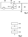
- Fig. 1 shows a schematic representation of a vehicle 100 with a device for displaying a traffic sign information according to an embodiment of the present invention.
- the vehicle 100 is traveling on a road 104.
- the vehicle 100 is currently located on a first section 106 of the road on which a first speed limit of, for example, 70 km / h applies.
- a first speed limit for example, 70 km / h applies.
- the speed limit changes.
- a second speed limit of, for example, 30 km / h applies.
- the device has a device 112, for example a navigation device, and a device 114 for generating a display signal for a projection device 116, for example in the form of a head-up display.
- a device 112 for example a navigation device
- a device 114 for generating a display signal for a projection device 116, for example in the form of a head-up display.
- the device 112 is designed to determine a current location of the vehicle 100, for example with the aid of a GPS receiver.
- the device 112 is further configured to determine or obtain a future travel route of the vehicle 100.
- the device 112 is designed to determine traffic sign information relating to the future travel route.
- the device 112 is thus designed to determine the position 108 along the travel route of the vehicle 100, which is associated with a beginning of a validity range of the traffic sign information.
- the device 112 may be configured to determine the current location of the vehicle 100, determine that the future route of the vehicle 100 from the first portion 106 of the lane 104 opens into the second portion 110 and further determine that the position 108 a transition between the first Section 106 and the second section 110 is a traffic sign information, here in the form of the new speed limit of 30 km / h is assigned.
- the device 112 may further be configured to determine a distance between the current location of the vehicle 100 and the position 108 of the traffic sign information.
- the device 112 may be configured to access stored map material.
- the device 112 is designed to output relevant data, for example via the position 108, the distance between the current location of the vehicle 100 and the position 108 and the information content of the traffic sign information to the device 114 for generating an indication signal.
- the device 114 is designed to generate, on the basis of the data of the device 112, an indication signal for displaying the traffic sign information as a position-related contact-analogue virtual representation and to output it via an interface to the projection device 116.
- the device 114 is designed to determine data regarding the type, shape and position of the representation of the traffic sign information and to incorporate it in the generation of the indication signal.
- means 114 is configured to select a suitable representation for the traffic sign information associated with position 108.
- the device 114 is designed to select, as an illustration of the speed limit, a representation of a corresponding traffic sign with the speed limit at the speed of 30 km / h.
- the device 114 is further configured to select a suitable location for a contact analog representation of the traffic sign information.
- the device 114 is configured so as to select a roadway surface of the roadway 104 at the position 108.
- a suitable location for example, a lateral boundary of the roadway 104 could be selected.
- the device 114 is further configured to determine a suitable extent of the representation of the traffic sign information at the position 108, for example with regard to the width and height of the representation. The extent may be dependent on a distance between the vehicle 100 and the position 108.
- the device 114 is also designed to determine a suitable contact-analogue representation of the representation of the traffic sign information.
- the device 114 may be configured to select a perspective distorted representation of the traffic sign information depending on the distance to the position 108, so that the traffic sign information appears from the perspective of a driver 120 of the vehicle as if the traffic sign information were on the road surface of the road 104 located.
- the device 114 is designed to output the display signal to the projection device 116 via an interface.
- the projection device 116 is designed to generate a projection in response to the display signal, by means of which a representation of the traffic sign information in the manner determined by the device 114 is generated.
- the device 112 is configured to provide continuously updated data to the device 114.
- the device 114 is designed to generate continuously updated display signals based on the updated data of the device 112 and to provide them to the projection device 116.
- the projection device 116 is designed to generate continuously updated representations of the traffic sign information based on the continuously updated display signals.
- the device 114 may be configured to generate an indication signal for displaying the traffic sign information for the first time when the vehicle 100 has approached the position 108 so far that the position 108 lies in the virtual field of view of the projection device 116.
- the virtual field of view of the projection device 116 may, for example, have a maximum extent to the horizon in advance of the vehicle.
- the device 112 is configured to generate another display signal for displaying the traffic sign information as a non-contact analog virtual representation.
- the device 112 may be configured to generate the further display signal for displaying the traffic sign information in the non-contact virtual representation instead of the indication signal for displaying the traffic sign information in the non-contact virtual representation when the vehicle 100 is at a certain distance to the Position 108 has approximated.
- the device 112 may be configured to generate a further indication signal for generating the traffic sign information as the non-contact analog virtual representation when the vehicle 100 has approached the position 108 so far that the position 108 is outside the virtual field of view of the projection device 116.
- the virtual field of view of the projection device 116 may begin at a distance of about 15 in front of the vehicle 100.
- Means 112 is configured to maintain the further indication signal until the traffic sign information becomes invalid or is replaced by a new non-contact analog virtual representation of new traffic sign information.
- means 112 is configured to generate a presentation signal to represent a status information field as a non-contact analog virtual representation.
- the status information field may be displayed as a partially transparent representation in a field of view of the driver 120.
- up-to-date vehicle data or environmental data can be displayed.
- the device 112 may be connected via an interface to sensors or evaluation devices that provide corresponding data.
- the status information field can be displayed independently of the traffic sign information, that is to say even if no contact-analogue or non-contact-analog representation of the traffic sign information takes place.
- the means 112 is configured to generate the further indication signal for displaying the traffic sign information as the non-contact analog virtual representation such that the traffic sign information is displayed within a display area of the status information field.
- the device 112 can be designed to suitably combine signals for displaying the traffic sign information and the status information field.
- Embodiments for displaying and animating the traffic sign information and the status information field will be described below with reference to FIGS. 4 to 9 described.
- the projection device 116 may be a head-up display disposed adjacent to the windshield of the vehicle to project representations into the field of view of the driver 120 or other occupants of the vehicle 100.
- a head-up display can be realized by means of an imager and an imaging optics.
- a projection unit consisting of imager and imaging optics can generally be installed together with the image object generator in a housing which can be integrated in a dashboard of the vehicle.
- the device 112 can also take into account, for example, vehicle movements as well as the driver's eye position by evaluating suitable sensor data during generation of the indication signal.
- the device 112 may be configured to generate the display signal for contact analog representation of the traffic sign information so that the traffic sign information is displayed at least partially distorted.
- a representation of the traffic sign information may be distorted so that the driver 120 gets the impression that the traffic sign information lies directly on the road surface.
- the device 112 may be configured to generate the further display signal for non-contact-analog representation of the traffic sign information and the display signal for displaying the status information field so that the traffic sign information and the status information field undistorted, ie standing, or slightly tilted perspective view.
- the status information field can be circular in nature, but appear oval through the slightly perspective view.
- FIG. 10 is a flowchart of a method of displaying traffic sign information according to an embodiment of the present invention.
- the method can be used, for example, by suitable devices of the type described in US Pat
- Fig. 1 shown vehicle 100 are implemented.
- a step 212 a determination is made of a position lying along a travel route of the vehicle, which is assigned a start of a validity range of the traffic sign information.
- a display signal for displaying the traffic sign information is generated as a position-related contact-analog virtual representation.
- the display of the traffic sign information may be performed as the position-related contact-analog virtual representation by means of a projection device.
- the steps 212, 214, 216 may be repeatedly executed repeatedly.
- further signals for displaying further information in particular the status information field, can be generated by means of the projection device.
- Fig. 3 shows a block diagram of an embodiment of the present invention.
- a GPS signal 311 is received by an evaluation system 112.
- the evaluation system 112 is designed to evaluate the GPS signal 311 in order to generate evaluated data.
- the evaluated data may include, for example, a lying along a route of a vehicle position of a traffic sign.
- the evaluation system 112 is further configured to output the evaluated data to an output system 114.
- the output system 114 is designed to generate one or more image signals based on the evaluated data and to output them to a head-up display 116.
- the head-up display 116 is designed to generate displays based on the image signals of the output system 114, as shown for example in US Pat FIGS. 4 to 6 are shown.
- the GPS signal 311 comprises a current position of the vehicle 100.
- the evaluation system 112 and the output system 114 are configured to provide suitable data for generating the traffic sign information as well as the status information field by the projection device 116 to generate.
- This in Fig. 3 embodiment shown can thus in the in Fig. 1 shown vehicle implemented as a device for displaying a traffic sign information.
- FIGS. 4 to 6 12 show schematic representations of projected traffic sign information 420, 422 and a projected status information field 424 according to embodiments of the present invention.
- the representations 420, 422, 424 may be different from those in FIG Fig. 1 shown projection device 116 or of the in Fig. 3 shown head-up display 116 are generated.
- Fig. 4 shows a portion of a roadway 104 ahead of a vehicle that is in the field of view of a driver of the vehicle. Into the field of view, a contact analog traffic sign information 420, a non-contact analog traffic sign information 422 and a non-contact analog status information field 424 are projected.
- the contact analog traffic sign information 420 is shown in perspective distorted so that it seems to be on the surface of the road 104 from the driver's point of view. According to this embodiment, the contact analog traffic sign information 420 appears within a current traffic lane of the vehicle.
- the contact analog traffic sign information 420 is shown at a position 108 of the roadway 104. At the position 108, a maximum permissible speed changes from currently 70 km / h to subsequently 30 km / h.
- a traffic sign is displayed, which shows the number 30, which corresponds to the subsequent speed limit, within a ring.
- the representation of the contact-analog traffic sign information 420 has a horizontal extent, which extends, for example, approximately over an entire width of a lane of the lane 104.
- the non-contact analog status information field 424 is shown slightly tilted in perspective in a lower field of view of the driver.
- the status information field 424 comprises a ring, for example in oval form, in which an actual speed of the vehicle, here 34 km / h is displayed. Further, in the status information field 424, the non-contact analog traffic sign information 422 is displayed.
- the non-contact analog traffic sign information 422 is slightly tilted in perspective corresponding to the status information field 424.
- the non-contact analog traffic sign information 422 represents a traffic sign that shows the number 70 corresponding to the current speed limit within a ring.
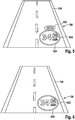
- Fig. 5 shows a portion of the road 104 in the apron of the vehicle, which is in the field of vision of the driver of the vehicle, after the vehicle compared to the in Fig. 4 shown state of the position 108 has approximated.
- contact analog traffic sign information 420 Also included in the field of view are contact analog traffic sign information 420, non-contact analog traffic sign information 422, and non-contact analog status information field 424. Shown is a transition of the contact-analog traffic sign information 420 into the status area represented by the non-contact analog status information field 424.
- the contact analog traffic sign information 420 is further shown in perspective distorted so that it seems to be on the surface of the road 104 from the driver's point of view.
- the contact analog traffic sign information 420 is further shown at a position 108 of the roadway 104.
- the representation of the contact-analog traffic sign information 420 has a horizontal extension that extends, for example, approximately over one half of the entire width of the lane of the roadway 104. Thus, the extent of the representation of the contact-analog traffic sign information 420 compared to that in the Fig. 3 reduced situation shown.
- the representation of the contact analog traffic sign information 420 approaches the representation of the non-contact analog status information field 424 as the vehicle approaches position 108.
- a representation of the contact-analog traffic sign information 420 and the non-contact-analog traffic sign information 422 is selected so that the contact analog traffic sign information 420 approaches the representation of the non-contact traffic sign information 422 as the vehicle approaches the position 108 both spatially and expansively.
- the contact-analog traffic sign information 420 may eventually appear to transition to the non-contact analog traffic sign information 422 when the vehicle has approached position 108 accordingly.
- the beginning of the overlap between the contact-analog traffic sign information 420 and the non-contact-analog status information field 424 may be selected so that the beginning of the overlap coincides with a disappearance of the position 108 from the virtual field of view of the head-up display.
- Fig. 6 shows a portion of the road 104 in the apron of the vehicle, which is in the field of vision of the driver of the vehicle, after the vehicle compared to the in Fig. 5 shown state of the position 108 has approached or the position 108 has already reached or exceeded.
- the contact analog traffic sign information is no longer shown.
- FIGS. 7 to 9 show the FIGS. 4 to 6 corresponding representations with the difference that instead of a schematic representation of a roadway in the field of view of the driver a real environment is shown.
- the invention enables a transmission of traffic sign information, for example, maximum speed information, through a virtual, contact-analog display 420 of the speed limit on the road 104 and an animation of the speed limit in the status display 424.
- the maximum permissible speed is permanently using Assistance systems 112, 114 displayed in a status line of the status display 424.
- the invention thus enables visualization of the speed limit update.
- the visualization is converted into the status line by means of an animation from the contact-analogue display 420 on the roadway 104 in the virtual space.
- An advantage lies in the clarification of the new information about the maximum speed. This is especially true when changing the speed zone. This approach provides a significant contribution to the faster acquisition of information and thus an increase in road safety and relieving the driver 120. The driver 120 must never turn away from the roadway 104 to detect the maximum speed allowed.
- a GPS signal 311 or a signal of a video camera an evaluation system 112
- AR-HUD Augmented Reality Head-up Display
- the vehicle position and the maximum permissible speed are determined at the current or the future position.
- a navigation satellite system which supplies the GPS signal 311
- the vehicle position and the maximum permissible speed are determined at the current or the future position.
- a video camera and image recognition algorithms objects such.
- B. traffic signs recognize from video images and their position data z.
- the evaluation system 112 If the evaluation system 112 receives transmitted information about a new speed limit, it hands it over to the output system 114, which displays the virtual display 420 of the speed limit via the head-up display 116 on the lane 104.
- the animation begins upon reaching the virtual field of view of the head-up display 116, as in Fig. 4 shown, and ends when leaving the virtual field of view of the head-up display 116, as in Fig. 5 shown.
- Fig. 5 As shown leaving the virtual field of view of the head-up display 116, an intermediate stage of the animation is performed. From this point onwards, the information about the new speed limit is in the status bar of the status display 424, as shown in FIG Fig. 6 is shown. There, the visualization remains as road sign 422 permanently, or until the next change, or cancellation of the speed limit.
- the display including the animation is an iterative function.
- the representations 420, 422, 424 in the FIGS. 4 to 6 are chosen only as an example. There are each versions of the representations 420, 422, 424 in any colors, shapes and sizes possible.
- the representations 420, 422, 424 are visible on the basis of a viewing of the image displayed in the head-up display 116.
- the embodiments primarily refer to an animation of a virtual speed limit in a status display 424
- the corresponding algorithm and representation is applicable to any type of traffic sign, e.g. B. Wild Touch, traffic-calmed zone, overtaking ban or danger of slipping in the wet.
- the navigation can also be displayed in the same way.
- a navigation arrow, a blackboard with directional display or similar representation can be animated in the status bar of the status display 424 when approaching a maneuver point.
- the method for displaying traffic sign information can be generally used as a method of presentation a traffic control function for a driver of a vehicle.
Description
Die vorliegende Erfindung bezieht sich auf ein Verfahren und auf eine Vorrichtung zur Darstellung einer Verkehrszeicheninformation, auf eine entsprechende Vorrichtung sowie auf ein entsprechendes Computerprogrammprodukt.The present invention relates to a method and apparatus for displaying traffic sign information, to a corresponding device and to a corresponding computer program product.
Die
Die
Vor diesem Hintergrund wird mit der vorliegenden Erfindung ein Verfahren zur Darstellung einer Verkehrszeicheninformation, weiterhin eine Vorrichtung, die dieses Verfahren verwendet sowie schließlich ein entsprechendes Computerprogrammprodukt gemäß den Hauptansprüchen vorgestellt. Vorteilhafte Ausgestaltungen ergeben sich aus den jeweiligen Unteransprüchen und der nachfolgenden Beschreibung.Against this background, the present invention provides a method for displaying traffic sign information, furthermore a device which uses this method and finally a corresponding computer program product presented according to the main claims. Advantageous embodiments emerge from the respective subclaims and the following description.
Als Head-up Display wird ein System bezeichnet, das Informationen direkt ins Sichtfeld des Fahrers eines Fahrzeugs einblendet. Im Gegensatz dazu muss der Fahrer bei einem Head-down Display oder bei den Kombiinstrumenten im Fahrzeug seinen Blick senken, um wichtige Anzeigen wie etwa Geschwindigkeit oder Richtungsanweisungen zu sehen. Obwohl die Daten bei einem Head-up Display direkt auf die Windschutzscheibe projiziert werden, entsteht für den Fahrer der Eindruck, dass das Bild ca. zweieinhalb Meter von ihm entfernt über der Motorhaube schwebt. Dies hat den Vorteil, dass der Fahrer den Blick nicht mehr vom Verkehrsgeschehen abwenden muss.A head-up display is a system that displays information directly into the driver's field of vision. In contrast, in a head-down display or in the instrument cluster in the vehicle, the driver must look down to see important indications such as speed or directional guidance. Although the data is projected directly onto the windshield with a head-up display, the driver gets the impression that the image is about two and a half meters away from him above the bonnet floats. This has the advantage that the driver no longer has to avert his gaze from the traffic.
Head-up Displays können Informationen auch direkt in das reale Bild einblenden. Diese Displays werden im allgemeinen Sprachgebrauch kontaktanaloge bzw. Augmented Reality Head-up Displays genannt. Dem Fahrer können mit Hilfe dieser Technik z. B. Navigationshinweise gegeben werden, indem die vor ihm liegende Straße bis zum Horizont farbig markiert. Auch können Navigationshinweise angezeigt werden, die als Pfeile direkt auf der Fahrbahn liegen. Auch Fahrspuren oder vom ACC-System, also einem System zur adaptiven Geschwindigkeitsregelung, detektierte vorausfahrende Fahrzeuge können direkt in das Blickfeld des Fahrers eingeblendet werden. Das Bild wird in einer akkommodationsfreien Entfernung von ca. 10 m bis zum Horizont, dem virtuellen Blickfeld des Head-up Displays, erzeugt.Head-up displays can also display information directly in the real image. These displays are commonly referred to as contact analogue or augmented reality head-up displays. The driver can with the help of this technique z. B. navigation instructions are given by the colored road in front of him to the horizon marked. Also, navigation instructions can be displayed, which lie as arrows directly on the road. Even lanes or ACC-system, so an adaptive cruise control system, detected vehicles ahead can be displayed directly in the driver's field of view. The image is generated in an accommodation-free distance of about 10 m to the horizon, the virtual field of view of the head-up display.
Ein kontaktanaloges Head-up Display kann eingesetzt werden, um dem Fahrer einen Hinweis auf eine sich auf einen zu befahrenden Streckenabschnitt beziehende Warnung direkt in sein Sichtfeld zu projizieren. Entsprechend zu einer Warnung kann dem Fahrer einen Hinweis auf ein sich auf den zu befahrenden Streckenabschnitt beziehendes Gebot oder Verbot direkt in sein Sichtfeld projiziert werden. Die Projizierung kann dabei so erfolgen, dass der Hinweis an eine Position in das reale Umfeld des Fahrzeugs eingebettet wird, die dem Fahrer das Aufnehmen und Verstehen des Hinweises erleichtert. Beispielsweise kann der Hinweis direkt auf eine Oberfläche eines für den Fahrer sichtbaren Abschnitts einer Fahrbahn projiziert werden. Beispielsweise kann der Hinweis an eine Position projiziert werden, ab der der Hinweis Gültigkeit hat. Nähert sich das Fahrzeug soweit an die Position an, das die Position innerhalb des virtuellen Blickfelds des Head-up Displays liegt, so kann der Hinweis von dem Head-up Display kontaktanalog an die Position projiziert werden. Aus Sicht des Fahrers erscheint der Hinweis so, als ob er sich tatsächlich in der realen Umwelt an der Position befinden würde. Nähert sich das Fahrzeug weiter an die Position an, so kann der Hinweis von dem Head-up Display unter Berücksichtigung des verringerten Abstands weiterhin kontaktanalog an die Position projiziert werden. Der Fahrer hat somit das Gefühl, dass er sich an den Hinweis annähert, so wie es bei einem realen Hinweis der Fall ist, der beispielsweise auf die Fahrbahnoberfläche aufgebracht ist. Der kontaktanaloge Hinweis kann zusammen mit einem nicht-kontaktanalog in das Sichtfeld des Fahrers projizierten Statusinformationsfeld eingesetzt werden. Der kontaktanalog projizierte Hinweis und das nicht-kontaktanaloge projizierte Statusinformationsfeld können so in das Sichtfeld des Fahrers projiziert werden, dass der kontaktanalog projizierte Hinweis bei der Annäherung des Fahrzeugs an die Position des kontaktanalogen Hinweises aus Sicht des Fahrers in das Statusinformationsfeld hineinwandert und schließlich von dem Statusinformationsfeld übernommen wird und dort, solange der Hinweis Gültigkeit hat, als nicht-kontaktanaloger Hinweis bestehen bleibt. Selbst wenn der Fahrer des Fahrzeugs, beispielsweise aufgrund hoher Geschwindigkeit keine Zeit hatte, den kontaktanalogen Hinweis aufzunehmen, so wird er durch das Hineinwandern des kontaktanalogen Hinweis in das nicht-kontaktanaloge Statusinformationsfeld darauf aufmerksam gemacht, dass eine Veränderung in der Anzeige des Statusinformationsfelds erfolgt. Aufgrund der anschließenden dauerhaften Anzeige des Hinweises als Teil des Statusinformationsfelds hat der Fahrer genügend Zeit, den Informationsgehalt des Hinweises aufzunehmen.A contact-analogue head-up display can be used to project the driver an indication of a warning relating to a section of the route to be driven directly into his field of vision. According to a warning, the driver can be projected an indication of a bid or prohibition relating to the route section to be driven directly into his field of vision. The projection can take place in such a way that the reference to a position is embedded in the real environment of the vehicle, which makes it easier for the driver to record and understand the message. For example, the hint may be projected directly onto a surface of a driver-visible portion of a roadway. For example, the hint can be projected to a position at which the hint is valid. If the vehicle approaches the position that lies within the virtual field of view of the head-up display, the message can be projected by the head-up display into contact with the position. From the driver's point of view, the note appears as if it were actually in the real environment at the position. If the vehicle continues to approach the position, the reference from the head-up display, taking into account the reduced distance, can continue to be projected contact-analogically to the position. The driver thus has the feeling that he is approaching the hint, as is the case with a real reference, for example, applied to the road surface. The contact analog indication can be used together with a non-contact analog be used in the field of view of the driver projected status information field. The contact-analog projected indication and the non-contact-analogous projected status information field may be projected into the driver's field of view such that the proximity-projected indication migrates into the status information field as the vehicle approaches the location of the contact-analog indication from the driver's point of view, and finally from the status information field is taken over there and, as long as the note is valid, remains as a non-contact-analogous hint. Even if the driver of the vehicle, for example due to high speed, did not have time to record the contact analog indication, he is made aware by the intrusion of the contact analog indication into the non-contact analog status information field that there is a change in the display of the status information field. Due to the subsequent permanent display of the hint as part of the status information field, the driver has enough time to record the information content of the hint.
Ein Verfahren zur Darstellung einer Verkehrszeicheninformation für einen Fahrer eines Fahrzeugs umfasst die folgenden Schritte:
- Ermitteln einer entlang einer Fahrtroute des Fahrzeugs liegenden Position, der ein Beginn eines Gültigkeitsbereichs der Verkehrszeicheninformation zugeordnet ist; und
- Erzeugen eines Anzeigesignals zur Anzeige der Verkehrszeicheninformation als eine auf die Position bezogene kontaktanaloge virtuelle Darstellung.
- Determining a position along a travel route of the vehicle associated with a beginning of a valid range of the traffic sign information; and
- Generating a display signal for displaying the traffic sign information as a position-related contact-analog virtual representation.
Bei dem Fahrzeug kann es sich um ein Kraftfahrzeug, beispielsweise einen Personenkraftwagen oder einen Lastkraftwagen handeln. Das Fahrzeug kann eine Projektionseinrichtung, beispielsweise in Form eines Head-up Displays aufweisen. Die Projektionseinrichtung kann ausgebildet sein, um sowohl eine kontaktanaloge als auch eine nicht-kontaktanaloge Anzeige in einen Sichtbereich des Fahrers des Fahrzeugs zu projizieren. Das Anzeigesignal kann ein elektrisches Signal sein. Das Anzeigesignal kann geeignet sein, um die Projektionseinrichtung so anzusteuern, dass die Projektionseinrichtung die Verkehrszeicheninformation als kontaktanaloge virtuelle Darstellung in das Sichtfeld des Fahrers projiziert. Die Verkehrszeicheninformation kann eine Information eines Gefahrzeichens, das auf eine Gefahr hinweist oder eine Information eines Vorschriftzeichens, das auf ein Gebot oder ein Verbot hinweist, umfassen. Demnach kann die Verkehrszeicheninformation in Form eines entsprechenden Verkehrszeichens oder einem einen Verkehrszeichen ähnelndem Piktogramm angezeigt werden. Beispielsweise kann die Verkehrszeicheninformation auf ein Tempolimit hinweisen und in Form eines Geschwindigkeitsbegrenzungszeichens dargestellt werden. Bei der Fahrtroute kann es sich um einen geplanten Verlauf eines vor dem Fahrzeug liegenden Streckenabschnitts handeln. Daten bezüglich der Fahrtroute können von einem Navigationssystem des Fahrzeugs ausgegeben werden. Der Beginn des Gültigkeitsbereichs der Verkehrszeicheninformation kann basierend auf gespeicherten Daten ermittelt werden. Die Daten bezüglich des Gültigkeitsbereichs können in einer Speichereinrichtung, beispielsweise in Form einer digitalen Karte in dem Fahrzeug gespeichert sein oder über eine Schnittstelle von einer fahrzeugexternen Speichereinrichtung abgerufen werden. Die Position kann einen realen Ort kennzeichnen, der im Bereich des Beginns des Gültigkeitsbereichs angeordnet ist. Beispielsweise kann die Position direkt am Beginn, kurz vor dem Beginn oder kurz nach dem Beginn des Gültigkeitsbereichs angeordnet sein. Die Position kann einen Ort auf einer von dem Fahrzeug zu befahrenden Fahrbahn kennzeichnen. Auch kann die Position einen Ort kennzeichnen, der neben der zu befahrenden Fahrbahn angeordnet ist.The vehicle may be a motor vehicle, for example a passenger car or a lorry. The vehicle may have a projection device, for example in the form of a head-up display. The projection device can be designed to project both a contact-analog and a non-contact-analogue display into a field of vision of the driver of the vehicle. The indication signal may be an electrical signal. The display signal may be suitable for controlling the projection device in such a way that the projection device projects the traffic sign information into the driver's field of view as a contact-analogous virtual representation. The traffic sign information may include information of a danger sign, which indicates a danger or information of a mandatory sign indicating a bid or a ban. Thus, the traffic sign information may be displayed in the form of a corresponding traffic sign or a pictogram resembling a traffic sign. For example, the traffic sign information may indicate a speed limit and be presented in the form of a speed limit sign. The route may be a planned course of a section of road ahead of the vehicle. Data regarding the route can be output from a navigation system of the vehicle. The beginning of the validity period of the traffic sign information may be determined based on stored data. The data relating to the validity range can be stored in a memory device, for example in the form of a digital map, in the vehicle or can be retrieved via an interface from a vehicle-external memory device. The position may indicate a real location located at the beginning of the scope. For example, the position can be arranged directly at the beginning, shortly before the beginning or shortly after the beginning of the validity range. The position may indicate a location on a roadway to be traveled by the vehicle. Also, the position may identify a location that is located next to the roadway to be traveled.
Im Schritt des Erzeugens können unterschiedliche Anzeigesignale für unterschiedliche Abstände zwischen dem Fahrzeug und der Position erzeugt werden. Dadurch kann die Verkehrszeicheninformation als auf die Position bezogene kontaktanaloge virtuelle Darstellung mit unterschiedlichen Ausdehnungen angezeigt werden. Ändert sich der Abstand zwischen dem Fahrzeug und der Position so kann ein neues Anzeigesignal erzeugt werden, um zu gewährleisten, dass die Verkehrszeicheninformation aus Sicht des Fahrers weiterhin an der Position angezeigt wird. Die unterschiedlichen Anzeigesignale können zeitlich nacheinander erzeugt werden. Beispielsweise kann ein neues Anzeigesignal erzeugt werden, wenn nach einem vorangegangenen Anzeigesignal eine vorbestimmte Zeitspanne vergangen oder ein vorbestimmter Weg zurückgelegt wurde. Abgesehen von der Ausdehnung kann die Form und Darstellung der Verkehrszeicheninformation in den unterschiedlichen Anzeigesignalen gleich sein. Aufgrund der unterschiedlichen Ausdehnungen erscheint die Verkehrszeicheninformation aus Sicht des Fahrers bei unterschiedlichen Abständen zu der Position in unterschiedlichen Größen.In the step of generating different display signals for different distances between the vehicle and the position can be generated. Thereby, the traffic sign information can be displayed as position-related contact-analog virtual representation with different extents. If the distance between the vehicle and the position changes, a new indication signal can be generated to ensure that the traffic sign information continues to be displayed at the position from the driver's point of view. The different display signals can be generated one after the other. For example, a new indication signal may be generated when a predetermined time period has elapsed or a predetermined distance traveled after a previous indication signal. Apart from the extent, the shape and appearance of the traffic sign information in the different display signals may be the same. Due to the different dimensions of the traffic sign information appears from the perspective of Driver at different distances to the position in different sizes.
Beispielsweise können die unterschiedlichen Anzeigesignale so erzeugt werden, dass die unterschiedlichen Ausdehnungen der auf die Position bezogenen kontaktanalogen virtuellen Darstellungen in einem ersten Abstandsbereich umso größer werden, je kleiner die Abstände zwischen dem Fahrzeug und der Position werden und in einem zweiten Abstandsbereich umso kleiner werden, je kleiner die Abstände zwischen dem Fahrzeug und der Position werden, wobei die von dem zweiten Abstandsbereich umfassten Abstände kleiner als die von dem ersten Abstandsbereich umfassten Abstände sind. Nähert sich das Fahrzeug der Position an, so scheint die Verkehrszeicheninformation entsprechend einer realen Darstellung zunächst größer zu werden. Ab einem gewissen Abstand, der eine Grenze zwischen dem ersten und dem zweiten Abstandbereich markiert, wird die Verkehrszeicheninformation jedoch immer kleiner dargestellt. Dadurch kann die Verkehrszeicheninformation beim Hineinwandern in ein Statusinformationsfeld soweit geschrumpft werden, dass die Verkehrsinformation innerhalb des Statusinformationsfelds angezeigt werden kann. Dabei kann die Verkehrsinformation soweit verkleinert werden, dass sie deckungsgleich zu einer innerhalb des Statusinformationsfelds angezeigten nicht-kontaktanalogen Verkehrsinformation wird.For example, the different display signals may be generated such that the smaller the distances between the vehicle and the position, the smaller the distances between the position-related contact-analog virtual representations in a first distance range, and the smaller in a second distance range, depending becomes smaller the distances between the vehicle and the position, wherein the distances covered by the second distance range are smaller than the distances covered by the first distance range. When the vehicle approaches the position, the traffic sign information initially appears to increase in accordance with a real representation. However, from a certain distance marking a boundary between the first and second distance ranges, the traffic sign information is always made smaller. As a result, the traffic sign information can be shrunk to the extent that the traffic information can be displayed within the status information field when wandering into a status information field. In this case, the traffic information can be reduced to such an extent that it becomes congruent with a non-contact-analog traffic information displayed within the status information field.
Das Verfahren kann einen Schritt des Generierens eines Darstellungssignals zur Darstellung eines Statusinformationsfelds als eine nicht-kontaktanaloge virtuelle Darstellung umfassen. Das Statusinformationsfelds kann beispielsweise teiltransparent in das Sichtfeld des Fahrers projiziert werden. Innerhalb des Statusinformationsfelds kann beispielsweise ein Betriebszustand des Fahrzeugs, beispielsweise eine aktuelle Geschwindigkeit des Fahrzeugs angezeigt werden. Der Schritt des Generierens kann fortlaufend ausgeführt werden, so dass das Statusinformationsfeld ständig, beispielsweise immerwährend des Betriebs des Fahrzeugs oder immer dann, wenn sich das Fahrzeug in Fahrt befindet, angezeigt wird. Dabei kann die in dem Statusinformationsfelds angezeigte Information fortlaufend aktualisiert werden. Somit kann beispielsweise ständig die aktuelle Geschwindigkeit angezeigt werden. Das Statusinformationsfelds kann aus Sicht des Fahrers ständig an der gleichen Position in Bezug auf einen Bezugspunkt an dem Fahrzeug angezeigt werden.The method may include a step of generating a presentation signal to represent a status information field as a non-contact analog virtual representation. The status information field can, for example, be projected partially transparent into the field of view of the driver. Within the status information field, for example, an operating state of the vehicle, for example a current speed of the vehicle, can be displayed. The step of generating may be performed continuously so that the status information field is constantly displayed, for example, always during the operation of the vehicle or whenever the vehicle is in motion. In this case, the information displayed in the status information field can be continuously updated. Thus, for example, constantly the current speed can be displayed. The status information field may be constantly displayed at the same position with respect to a reference point on the vehicle from the driver's point of view.
Das Verfahren kann einen Schritt des Generierens eines weiteren Anzeigesignals zur Anzeige der Verkehrszeicheninformation als eine nicht-kontaktanaloge virtuelle Darstellung innerhalb eines Anzeigebereichs des Statusinformationsfelds umfassen. Abgesehen von der nicht-kontaktanalogen Darstellung kann die Form und Darstellung der Verkehrszeicheninformation innerhalb des Statusinformationsfelds der Form und Darstellung der kontaktanalogen Darstellung der Verkehrszeicheninformation entsprechen. Der Schritt des Generierens des weiteren Anzeigesignals kann anstelle des Schritts des Erzeugens des Anzeigesignals durchgeführt werden, so dass die nicht-kontaktanaloge Darstellung der Verkehrszeicheninformation dann erfolgt, wenn die kontaktanaloge Darstellung der Verkehrszeicheninformation beendet wird, beispielsweise aufgrund einer Annäherung des Fahrzeugs bis kurz vor die Position der kontaktanalogen Darstellung. Ferner kann das Verfahren einen Schritt des Generierens eines weiteren Anzeigesignals zur Anzeige einer vorangegangenen Verkehrszeicheninformation als eine nicht-kontaktanaloge virtuelle Darstellung innerhalb des Anzeigebereichs des Statusinformationsfelds umfassen. Der Schritt des Generierens des weiteren Anzeigesignals kann zusätzlich zu dem Schritt des Erzeugens des Anzeigesignals durchgeführt werden, so dass die nicht-kontaktanaloge Darstellung der vorangegangenen Verkehrszeicheninformation parallel zur kontaktanalogen Darstellung der neuen Verkehrszeicheninformation erfolgt. Auf diese Weise kann innerhalb des Statusinformationsfelds noch die vorangegangene, aktuell gültige Verkehrszeicheninformation, beispielsweise eine aktuell gültige Geschwindigkeitsbegrenzung angezeigt werden, während als kontaktanaloge Darstellung bereits die neue Verkehrszeicheninformation, beispielsweise eine demnächst gültige Geschwindigkeitsbegrenzung angezeigt wird.The method may include a step of generating a further indication signal for displaying the traffic sign information as a non-contact analog virtual representation within a display area of the status information field. Apart from the non-contact analog representation, the shape and presentation of the traffic sign information within the status information field may correspond to the shape and representation of the contact-analog representation of the traffic sign information. The step of generating the further indication signal may be performed instead of the step of generating the indication signal such that the non-contact analog representation of the traffic sign information occurs when the contact analog representation of the traffic sign information is terminated, for example due to approach of the vehicle to just before the position the contact analog representation. Furthermore, the method may include a step of generating a further indication signal for displaying a preceding traffic signal information as a non-contact analog virtual representation within the display region of the status information field. The step of generating the further indication signal can be carried out in addition to the step of generating the indication signal, so that the non-contact-analog representation of the preceding traffic signal information takes place in parallel to the contact-analog representation of the new traffic signal information. In this way, the previous, currently valid traffic sign information, for example, a currently valid speed limit can be displayed within the status information field, while the new traffic sign information, such as a soon-to-be speed limit is already displayed as contact-analog representation.
Beispielsweise kann der Schritt des Generierens des weiteren Anzeigesignals ausgeführt werden, wenn in einem ausgeführten Schritt des Erzeugens des Anzeigesignals das Anzeigesignal so erzeugt wurde das sich die Darstellung des Statusinformationsfelds und die kontaktanaloge virtuelle Darstellung der Verkehrszeicheninformation zumindest teilweise überlappen. Dies ist dann der Fall, wenn die kontaktanaloge Darstellung der Verkehrszeicheninformation aus Sicht des Fahrers in das Statusinformationsfeld hineingewandert ist. Das Umschalten zwischen kontaktanaloger oder nicht-kontaktanaloger Darstellung kann erfolgen, sobald eine teilweise Überlappung vorliegt, sobald eine vollständige Überlappung vorliegt oder sobald die kontaktanaloge Darstellung einen für die nicht-kontaktanaloge Darstellung der Verkehrszeicheninformation erreicht hat. Auf diese Weise lässt sich ein fließender Übergang zwischen kontaktanaloger und nicht-kontaktanaloger Darstellung realisieren. Dabei können aufeinander folgende Anzeigesignale so erzeugt werden, dass eine perspektivisch verzerrte Darstellung der Verkehrszeicheninformation immer weiter verringert wird, so dass ein fließender Übergang von der kontaktanalogen Darstellung in die nicht-kontaktanaloge Darstellung erfolgen kann. In der nicht-kontaktanalogen Darstellung kann die Verkehrszeicheninformation nicht perspektivisch verzerrt oder nur geringfügig perspektivisch verzerrt dargestellt werden.For example, the step of generating the further indication signal may be performed if, in an executed step of generating the indication signal, the indication signal has been generated such that the representation of the status information field and the contact-analog virtual representation of the traffic sign information at least partially overlap. This is the case when the contact-analog representation of the traffic sign information has migrated from the perspective of the driver into the status information field. Switching between contact-analog or non-contact-analog representation may occur as soon as there is partial overlap as soon as there is complete overlap or as soon as the contact-analog representation becomes one for the non-contact analog Display of traffic sign information has reached. In this way, a smooth transition between contact-analog and non-contact analog representation can be realized. In this case, successive display signals can be generated so that a perspective distorted representation of the traffic sign information is reduced further and further, so that a smooth transition from the contact-analog representation in the non-contact analog representation can take place. In the non-contact analog presentation, the traffic sign information can not be distorted in perspective or only slightly distorted in perspective.
Auch kann der der Schritt des weiteren Erzeugens des weiteren Anzeigesignals ausgeführt werden, wenn ein Abstand zwischen dem Fahrzeug und der Position kleiner als ein Mindestabstand ist. Auf diese Weise kann beispielsweise dann zwischen kontaktanaloger und nicht-kontaktanaloger Darstellung umgeschaltet werden, wenn die Position der kontaktanalogen Darstellung das virtuelle Blickfeld der Projektionseinrichtung verlässt. Dies kann beispielsweise der Fall sein, wenn sich das Fahrzeug bis auf eine Entfernung von ca. 10 m bis 20 m an die Position angenähert hat.Also, the step of further generating the further indication signal may be performed when a distance between the vehicle and the position is smaller than a minimum distance. In this way, it is possible, for example, to switch between contact-analogous and non-contact-analogue representation if the position of the contact-analogue representation leaves the virtual field of view of the projection device. This may for example be the case when the vehicle has approached the position up to a distance of about 10 m to 20 m.
Das Verfahren kann einen Schritt des Aufrechterhaltens des weiteren Anzeigesignals bis zu einem Ende des Gültigkeitsbereichs der Verkehrszeicheninformation umfassen. Auf diese Weise kann die Verkehrszeicheninformation als nicht-kontaktanaloge Darstellung innerhalb des Statusinformationsfelds beibehalten werden, bis die Verkehrszeicheninformation entweder an Gültigkeit verliert oder durch eine neue Verkehrszeicheninformation ersetzt wird.The method may include a step of maintaining the further indication signal until an end of the validity range of the traffic sign information. In this way, the traffic sign information may be maintained as a non-contact analog representation within the status information field until the traffic sign information either becomes invalid or is replaced by new traffic sign information.
Ferner kann das Verfahren einen Schritt des Ausgebens des Anzeigesignals an eine Projektionseinrichtung des Fahrzeugs umfassen, um die Darstellung der Verkehrszeicheninformation mittels der Projektionseinrichtung zu bewirken. Dazu kann das Anzeigesignal über eine geeignete Schnittstelle an die Projektionseinrichtung übertragen werden. Bei der Projektionseinrichtung kann es sich um ein Head-up Display handeln.Furthermore, the method may include a step of outputting the indication signal to a projection device of the vehicle in order to effect the representation of the traffic sign information by means of the projection device. For this purpose, the display signal can be transmitted to the projection device via a suitable interface. The projection device may be a head-up display.
Eine Vorrichtung zur Darstellung einer Verkehrszeicheninformation ist ausgebildet, um die Schritte eines Verfahrens gemäß einer Ausführungsform der Erfindung durchzuführen. Die Vorrichtung kann ausgebildet sein, um die Schritte des erfindungsgemäßen Verfahrens in entsprechenden Einrichtungen durchzuführen bzw. umzusetzen. Auch durch diese Ausführungsvariante der Erfindung in Form einer Vorrichtung kann die der Erfindung zugrunde liegende Aufgabe schnell und effizient gelöst werden. Unter einer Vorrichtung kann vorliegend ein elektrisches Gerät verstanden werden, das Sensorsignale verarbeitet und in Abhängigkeit davon Steuer- und/oder Datensignale ausgibt. Die Vorrichtung kann eine Schnittstelle aufweisen, die hard- und/oder softwaremäßig ausgebildet sein kann. Bei einer hardwaremäßigen Ausbildung können die Schnittstellen beispielsweise Teil eines sogenannten System-ASICs sein, der verschiedenste Funktionen der Vorrichtung beinhaltet. Es ist jedoch auch möglich, dass die Schnittstellen eigene, integrierte Schaltkreise sind oder zumindest teilweise aus diskreten Bauelementen bestehen. Bei einer softwaremäßigen Ausbildung können die Schnittstellen Softwaremodule sein, die beispielsweise auf einem Mikrocontroller neben anderen Softwaremodulen vorhanden sind.A traffic sign information display device is configured to perform the steps of a method according to an embodiment of the invention. The device can be designed to carry out the steps of the method according to the invention in corresponding devices or implement. Also by this embodiment of the invention in the form of a device, the object underlying the invention can be solved quickly and efficiently. In the present case, a device can be understood as meaning an electrical device which processes sensor signals and outputs control and / or data signals in dependence thereon. The device may have an interface, which may be formed in hardware and / or software. In the case of a hardware-based embodiment, the interfaces can be part of a so-called system ASIC, for example, which contains a wide variety of functions of the device. However, it is also possible that the interfaces are their own integrated circuits or at least partially consist of discrete components. In a software training, the interfaces may be software modules that are present, for example, on a microcontroller in addition to other software modules.
Von Vorteil ist auch ein Computerprogrammprodukt mit Programmcode, der auf einem maschinenlesbaren Träger wie einem Halbleiterspeicher, einem Festplattenspeicher oder einem optischen Speicher gespeichert sein kann und zur Durchführung des Verfahrens nach einer der vorstehend beschriebenen Ausführungsformen verwendet wird, wenn das Programm auf einem Computer oder einer Vorrichtung ausgeführt wird.A computer program product with program code which can be stored on a machine-readable carrier such as a semiconductor memory, a hard disk memory or an optical memory and is used to carry out the method according to one of the embodiments described above if the program is installed on a computer or a device is also of advantage is performed.
Die Erfindung wird nachstehend anhand der beigefügten Zeichnungen beispielhaft näher erläutert. Es zeigen:
- Fig. 1
- eine schematisch Darstellung eines Fahrzeugs mit einer Vorrichtung zur Darstellung einer Verkehrszeicheninformation;
- Fig. 2
- ein Ablaufdiagramm eines Verfahrens zur Darstellung einer Verkehrszeicheninformation;
- Fig. 3
- ein Blockschaltbild eines Ausführungsbeispiels der vorliegenden Erfindung;
- Figuren 4 bis 6
- schematische Darstellungen einer projizierten Verkehrszeicheninformation; und
- Figuren 7 bis 9
- Darstellungen einer projizierten Verkehrszeicheninformation.
- Fig. 1
- a schematic representation of a vehicle with a device for displaying a traffic sign information;
- Fig. 2
- a flowchart of a method for displaying a traffic sign information;
- Fig. 3
- a block diagram of an embodiment of the present invention;
- FIGS. 4 to 6
- schematic representations of a projected traffic sign information; and
- FIGS. 7 to 9
- Representations of a projected traffic sign information.
In der nachfolgenden Beschreibung bevorzugter Ausführungsbeispiele der vorliegenden Erfindung werden für die in den verschiedenen Figuren dargestellten und ähnlich wirkenden Elemente gleiche oder ähnliche Bezugszeichen verwendet, wobei auf eine wiederholte Beschreibung dieser Elemente verzichtet wird.In the following description of preferred embodiments of the present invention, the same or similar reference numerals are used for the elements shown in the various figures and similarly acting, wherein a repeated description of these elements is omitted.
Die Vorrichtung weist gemäß diesem Ausführungsbeispiel eine Einrichtung 112, beispielsweise eine Navigationseinrichtung, und eine Einrichtung 114 zum Erzeugen eines Anzeigesignals für eine Projektionseinrichtung 116, beispielsweise in Form eines Head-up Displays, auf.According to this exemplary embodiment, the device has a
Die Einrichtung 112 ist ausgebildet, um einen aktuellen Ort des Fahrzeugs 100, beispielsweise mit Hilfe eines GPS-Empfängers, zu bestimmen. Die Einrichtung 112 ist ferner ausgebildet, um eine zukünftige Fahrtroute des Fahrzeugs 100 zu bestimmen oder zu erhalten. Ferner ist die Einrichtung 112 ausgebildet, um die zukünftige Fahrtroute betreffende Verkehrszeicheninformation zu ermitteln. Die Einrichtung 112 ist somit ausgebildet, um die entlang der Fahrtroute des Fahrzeugs 100 liegende Position 108, der ein Beginn eines Gültigkeitsbereichs der Verkehrszeicheninformation zugeordnet ist, zu ermitteln.The
Bezogen auf das in
Die Einrichtung 114 ist ausgebildet, um basierend auf den Daten der Einrichtung 112 ein Anzeigesignal zur Anzeige der Verkehrszeicheninformation als eine auf die Position bezogene kontaktanaloge virtuelle Darstellung zu erzeugen und über eine Schnittstelle an die Projektionseinrichtung 116 auszugeben. Zur Erzeugung des Anzeigesignals ist die Einrichtung 114 ausgebildet, um Daten hinsichtlich der Art, Form und Position der Darstellung der Verkehrszeicheninformation zu bestimmen und in die Erzeugung des Anzeigesignals einfließen zu lassen. So ist die Einrichtung 114 ausgebildet, um eine geeignete Darstellung für die der Position 108 zugeordnete Verkehrszeicheninformation auszuwählen. Gemäß diesem Ausführungsbeispiel ist die Einrichtung 114 ausgebildet, um als Darstellung der Geschwindigkeitsbegrenzung eine Darstellung eines entsprechenden Verkehrszeichens mit der Geschwindigkeitsbegrenzung auf die Geschwindigkeit von 30 km/h auszuwählen. Die Einrichtung 114 ist ferner ausgebildet, um einen geeignete Ort für eine kontaktanaloge Darstellung der Verkehrszeicheninformation auszuwählen. Gemäß diesem Ausführungsbeispiel ist die Einrichtung 114 ausgebildet, um also Ort eine Fahrbahnoberfläche der Fahrbahn 104 an der Position 108 auszuwählen. Alternativ könnte als geeigneter Ort beispielsweise auch eine seitliche Begrenzung der Fahrbahn 104 ausgewählt werden. Die Einrichtung 114 ist ferner ausgebildet, um eine geeignete Ausdehnung der Darstellung der Verkehrszeicheninformation an der Position 108 zu bestimmen, beispielsweise hinsichtlich der Breite und Höhe der Darstellung. Die Ausdehnung kann abhängig von einem Abstand zwischen dem Fahrzeug 100 und der Position 108 sein. Die Einrichtung 114 ist ferner ausgebildet, um eine geeignete kontaktanaloge Darstellungsform der Darstellung der Verkehrszeicheninformation zu bestimmen.The
Beispielsweise kann die Einrichtung 114 ausgebildet sein, um abhängig von dem Abstand zu der Position 108 eine perspektivisch verzerrte Darstellung der Verkehrszeicheninformation zu wählen, damit die Verkehrszeicheninformation aus Sicht eines Fahrers 120 des Fahrzeugs so erscheint, als ob sich die Verkehrszeicheninformation auf der Fahrbahnoberfläche der Fahrbahn 104 befindet. Die Einrichtung 114 ist ausgebildet, um das Anzeigesignal an die Projektionseinrichtung 116 über eine Schnittstelle auszugeben.For example, the
Die Projektionseinrichtung 116 ist ausgebildet, um ansprechend auf das Anzeigesignal eine Projektion zu erzeugen, durch die eine Darstellung der Verkehrszeicheninformation in der von der Einrichtung 114 bestimmten Art und Weise generiert wird.The
Die Einrichtung 112 ist ausgebildet, um fortlaufend aktualisierte Daten an die Einrichtung 114 bereitzustellen. Die Einrichtung 114 ist ausgebildet, um basierend auf den aktualisierten Daten der Einrichtung 112 fortlaufend aktualisierte Anzeigesignale zu erzeugen und an die Projektionseinrichtung 116 bereitzustellen. Die Projektionseinrichtung 116 ist ausgebildet, um basierend auf den fortlaufend aktualisierten Anzeigesignalen fortlaufend aktualisierte Darstellungen der Verkehrszeicheninformation zu generieren. Beispielsweise kann die Einrichtung 114 ausgebildet sein, um erstmalig ein Anzeigesignal zur Darstellung der Verkehrszeicheninformation zu erzeugen, wenn sich das Fahrzeug 100 soweit an die Position 108 angenähert hat, dass die Position 108 im virtuellen Blickfeld der Projektionseinrichtung 116 liegt. Das virtuelle Blickfeld der Projektionseinrichtung 116 kann beispielsweise eine maximale Ausdehnung bis zum Horizont im Vorfeld des Fahrzeugs aufweisen.The
Gemäß einem Ausführungsbeispiel ist die Einrichtung 112 ausgebildet, um ein weiteres Anzeigesignal zur Anzeige der Verkehrszeicheninformation als eine nicht-kontaktanaloge virtuelle Darstellung zu erzeugen. Beispielsweise kann die Einrichtung 112 ausgebildet sein, um anstelle des Anzeigesignals zur Anzeige der Verkehrszeicheninformation in der kontaktanlogen virtuellen Darstellung das weitere Anzeigesignal zur Anzeige der Verkehrszeicheninformation in der nicht-kontaktanlogen virtuelle Darstellung zu erzeugen, wenn sich das Fahrzeug 100 bis auf einen bestimmten Abstand an die Position 108 angenähert hat. Beispielsweise kann die Einrichtung 112 ausgebildet sein, um ein weiteres Anzeigesignal zur Darstellung der Verkehrszeicheninformation als die nicht-kontaktanaloge virtuelle Darstellung zu erzeugen, wenn sich das Fahrzeug 100 soweit an die Position 108 angenähert hat, dass die Position 108 außerhalb des virtuellen Blickfeld der Projektionseinrichtung 116 liegt. Das virtuelle Blickfeld der Projektionseinrichtung 116 kann beispielsweise bei einer Entfernung von ca. 15 vordem Fahrzeug 100 beginnen.In one embodiment, the
Die Einrichtung 112 ist ausgebildet, um das weitere Anzeigesignal aufrecht zu erhalten, bis die Verkehrszeicheninformation ungültig wird oder durch eine neue nicht-kontaktanaloge virtuelle Darstellung einer neuen Verkehrszeicheninformation ersetzt wird.
Gemäß einem Ausführungsbeispiel ist die Einrichtung 112 ausgebildet, um ein Darstellungssignal zur Darstellung eines Statusinformationsfelds als eine nicht-kontaktanaloge virtuelle Darstellung zu erzeugen. Das Statusinformationsfeld kann als eine teiltransparente Darstellung in ein Sichtfeld des Fahrers 120 eingeblendet werden. In dem Statusinformationsfeld können fortlaufend aktuelle Fahrzeugdaten oder Umfelddaten angezeigt werden. Zur Anzeige aktueller Daten in dem Statusinformationsfeld kann die Einrichtung 112 über eine Schnittstelle mit entsprechende Daten bereitstellenden Sensoren oder Auswerteeinrichtungen verbunden sein. Das Statusinformationsfeld kann unabhängig von der Verkehrszeicheninformation angezeigt werden, also auch dann, wenn keine kontaktanaloge oder nicht-kontaktanaloge Darstellung der Verkehrszeicheninformation erfolgt.In one embodiment, means 112 is configured to generate a presentation signal to represent a status information field as a non-contact analog virtual representation. The status information field may be displayed as a partially transparent representation in a field of view of the
Gemäß einem Ausführungsbeispiel ist die Einrichtung 112 ausgebildet, um das weitere Anzeigesignal zur Anzeige der Verkehrszeicheninformation als die nicht-kontaktanaloge virtuelle Darstellung so zu erzeugen, dass die Verkehrszeicheninformation innerhalb eines Anzeigebereichs des Statusinformationsfelds angezeigt wird. Dazu kann die Einrichtung 112 ausgebildet sein, um Signale zur Anzeige der Verkehrszeicheninformation und des Statusinformationsfelds geeignet zu kombinieren.According to one embodiment, the
Durch einen Übergang der Darstellung der Verkehrszeicheninformation von der kontaktanlogen Darstellung außerhalb des Statusinformationsfelds zur nicht-kontaktanlogen virtuelle Darstellung innerhalb des Statusinformationsfelds kann eine Animation der Darstellung der nicht-kontaktanlogen Verkehrszeicheninformation innerhalb des Statusinformationsfelds realisiert werden.By transitioning the representation of the traffic sign information from the contact-based representation outside the status information field to the non-contact-related virtual representation within the status information field an animation of the representation of the non-contact traffic sign information within the status information field can be realized.
Ausführungsbeispiele zur Darstellung und Animation der Verkehrszeicheninformation und des Statusinformationsfelds werden nachfolgend anhand der
Bei der Projektionseinrichtung 116 kann es sich um ein Head-up Display handeln, das benachbart zu der Windschutzscheibe des Fahrzeugs angeordnet ist, um Darstellungen in das Sichtfeld des Fahrer 120 oder weiterer Insassen des Fahrzeugs 100 zu projizieren. Optisch kann ein Head-up-Display mittels eines Bildgebers und einer Abbildungsoptik realisiert werden. Eine aus Bildgeber und Abbildungsoptik bestehende Projektionseinheit kann dabei in der Regel zusammen mit dem Bildobjektgenerator in ein Gehäuse eingebaut werden, das in ein Armaturenbrett des Fahrzeugs integriert sein kann.The
Neben der Anzeige statischer Informationen, wie zum Beispiel Betriebszuständen des Kraftfahrzeugs in dem Statusinformationsfeld können auch Informationen, welche einen Bezug zu realen Objekten im Sichtfeld des Fahrers 120 aufweisen, kontaktanalog dargestellt werden. Dabei werden Bildobjekte, beispielsweise eine Darstellung der Verkehrszeicheninformation, dem Fahrer 120 derart in seine aktuelle Sicht eingeblendet, dass er das Gefühl hat, als seien sie Bestandteil der Umwelt. Dem Fahrer 120 kann dadurch die Verkehrszeicheninformation beispielsweise direkt auf die vor ihm liegende Straße projiziert werden. Dabei ist es wichtig, dass die kontaktanalogen Bildobjekte als zur Fahrszene zugehörig wahrgenommen werden, also für das Fahrerauge durch entsprechende Form, Lage und Bewegung der realen Szene zugeordnet werden. Für eine möglichst reale Darstellung der Verkehrszeicheninformation können von der Einrichtung 112 beispielsweise auch Fahrzeugeigenbewegungen sowie die Augenposition des Fahrers durch Auswertung geeigneter Sensordaten bei der Erzeugung des Anzeigesignals berücksichtigt werden. Die Einrichtung 112 kann ausgebildet sein, um das Anzeigesignal zur kontaktanalogen Darstellung der Verkehrszeicheninformation so zu erzeugen, dass die Verkehrszeicheninformation zumindest teilweise verzerrt dargestellt wird. So kann eine Darstellung der Verkehrszeicheninformation so verzerrt werden, dass der Fahrer 120 den Eindruck erhält, dass die Verkehrszeicheninformation unmittelbar auf der Straßenoberfläche liegt. Demgegenüber kann die Einrichtung 112 ausgebildet sein, um das weitere Anzeigesignal zur nicht-kontaktanalogen Darstellung der Verkehrszeicheninformation sowie das Darstellungssignal zur Anzeige des Statusinformationsfeld so zu erzeugen, dass die Verkehrszeicheninformation und das Statusinformationsfeld unverzerrt, also stehend, oder aber leicht perspektivisch gekippt dargestellt werden. Beispielsweise kann das Statusinformationsfeld an sich kreisförmig sein, durch die leicht perspektivische Darstellung jedoch oval erscheinen.In addition to the display of static information, such as operating conditions of the motor vehicle in the status information field and information that have a relation to real objects in the field of view of the
Bezogen auf das in
Die
Die kontaktanaloge Verkehrszeicheninformation 420 ist perspektivisch verzerrt dargestellt, so dass sie aus Sicht des Fahrers auf der Oberfläche der Fahrbahn 104 zu liegen scheint. Gemäß diesem Ausführungsbeispiel erscheint die kontaktanaloge Verkehrszeicheninformation 420 innerhalb einer aktuellen Fahrspur des Fahrzeugs. Die kontaktanaloge Verkehrszeicheninformation 420 ist an einer Position 108 der Fahrbahn 104 dargestellt. An der Position 108 ändert sich eine zulässige Höchstgeschwindigkeit von aktuell 70 km/h auf nachfolgend 30 km/h. Durch die kontaktanaloge Verkehrszeicheninformation 420 wird ein Verkehrsschild dargestellt, das die Zahl 30, die dem nachfolgenden Tempolimit entspricht, innerhalb eines Rings zeigt. Die Darstellung der kontaktanalogen Verkehrszeicheninformation 420 weist eine horizontale Ausdehnung aus, die sich beispielsweise annähernd über eine gesamte Breite einer Fahrspur der Fahrbahn 104 erstreckt.The contact analog
Das nicht-kontaktanaloges Statusinformationsfeld 424 ist leicht perspektivisch gekippt in einem unteren Sichtbereich des Fahrers dargestellt. Das Statusinformationsfeld 424 umfasst einen Ring, beispielsweise in ovaler Form in dem eine aktuelle Geschwindigkeit des Fahrzeugs, hier 34 km/h angezeigt wird. Ferner wird in dem Statusinformationsfeld 424 die nicht-kontaktanaloge Verkehrszeicheninformation 422 angezeigt. Die nicht-kontaktanaloge Verkehrszeicheninformation 422 wird entsprechend zu dem Statusinformationsfeld 424 leicht perspektivisch gekippt dargestellt. Durch die nicht-kontaktanaloge Verkehrszeicheninformation 422 wird ein Verkehrsschild dargestellt, das die Zahl 70, die dem aktuellen Tempolimit entspricht, innerhalb eines Rings zeigt.The non-contact analog
Die kontaktanaloge Verkehrszeicheninformation 420 ist weiterhin perspektivisch verzerrt dargestellt, so dass sie aus Sicht des Fahrers auf der Oberfläche der Fahrbahn 104 zu liegen scheint. Die kontaktanaloge Verkehrszeicheninformation 420 ist weiterhin an einer Position 108 der Fahrbahn 104 dargestellt. Die Darstellung der kontaktanalogen Verkehrszeicheninformation 420 weist eine horizontale Ausdehnung aus, die sich beispielsweise annähernd über eine Hälfte der gesamten Breite der Fahrspur der Fahrbahn 104 erstreckt. Somit hat sich die Ausdehnung der Darstellung der kontaktanalogen Verkehrszeicheninformation 420 im Vergleich zu der in der in
Die Darstellungen des nicht-kontaktanalogen Statusinformationsfelds 424 mit der nicht-kontaktanalogen Verkehrszeicheninformation 422 sind unverändert im Vergleich zu der in der in
Aufgrund der statischen Darstellung des nicht-kontaktanalogen Statusinformationsfelds 424 mit der nicht-kontaktanalogen Verkehrszeicheninformation 422, nähert sich die Darstellung der kontaktanaloge Verkehrszeicheninformationen 420 aus Sicht des Fahrers bei einer Annäherung des Fahrzeugs an die Position 108 an die Darstellung des nicht-kontaktanalogen Statusinformationsfelds 424 an. In der in
Die kontaktanaloge Verkehrszeicheninformation ist nicht mehr dargestellt.The contact analog traffic sign information is no longer shown.
Die Darstellungen des nicht-kontaktanalogen Statusinformationsfelds 424 mit der nicht-kontaktanalogen Verkehrszeicheninformation 422 sind unverändert im Vergleich zu der in der in
Die
Anhand der
Gemäß einem Ausführungsbeispiel ermöglicht die Erfindung eine Übermittlung von Verkehrszeicheninformationen, beispielsweise von Informationen der zulässigen Höchstgeschwindigkeit, durch eine virtuelle, kontaktanaloge Anzeige 420 des Tempolimits auf der Fahrbahn 104 und eine Animation des Tempolimits in die Statusanzeige 424. Die zulässige Höchstgeschwindigkeit wird dabei permanent mit Hilfe von Assistenzsystemen 112, 114 in einer Statuszeile der Statusanzeige 424 angezeigt.According to one embodiment, the invention enables a transmission of traffic sign information, for example, maximum speed information, through a virtual, contact-
Die Erfindung ermöglicht somit eine Visualisierung der Geschwindigkeitsbegrenzungsaktualisierung. Die Visualisierung wird mittels einer Animation aus der kontaktanalogen Anzeige 420 auf der Fahrbahn 104 im virtuellen Raum in die Statuszeile umgesetzt. Ein Vorteil liegt dabei in der Verdeutlichung der neuen Information über die zulässige Höchstgeschwindigkeit. Dies gilt insbesondere bei einer Änderung der Geschwindigkeitszone. Dieser Ansatz liefert einen wesentlichen Beitrag zur schnelleren Erfassung von Informationen und somit eine Erhöhung der Verkehrssicherheit und Entlastung des Fahrers 120. Der Fahrer 120 muss zur Erfassung der zulässigen Höchstgeschwindigkeit in keinem Fall den Blick von der Fahrbahn 104 abwenden.The invention thus enables visualization of the speed limit update. The visualization is converted into the status line by means of an animation from the contact-
Gemäß einem Ausführungsbeispiel werden für eine Vorrichtung zur Darstellung einer Verkehrszeicheninformation als Komponenten ein GPS-Signal 311 oder ein Signal einer Videokamera, ein Auswertesystem 112, ein Ausgabesystem 114 und ein kontaktanaloges Head-up Display 116 (AR-HUD; AR-HUD = Augmented Reality Head-up Display) benutzt.According to one embodiment, for a device for displaying traffic sign information as components, a
Über ein Navigationssatellitensystem, das das GPS-Signal 311 liefert, werden die Fahrzeugposition und die zulässige Höchstgeschwindigkeit an der aktuellen, bzw. der zukünftigen Position ermittelt. Auch besteht die Möglichkeit mittels einer Videokamera und Bilderkennungsalgorithmen Objekte, z. B. Verkehrsschilder aus Videobildern zu erkennen und deren Positionsdaten z. B. über den CAN-BUS anderen Systemen, beispielsweise dem Auswertesystem 112 zur Verfügung zu stellen.Via a navigation satellite system, which supplies the
Empfängt das Auswertesystem 112 eine übermittelte Information zu einer neuen Geschwindigkeitsbegrenzung, so übergibt es diese an das Ausgabesystem 114, welches die virtuelle Anzeige 420 des Tempolimits über das Head-up Display 116 auf der Fahrbahn 104 anzeigt.If the
Die Animation beginnt bei Erreichen des virtuellen Blickfeldes des Head-up Displays 116, wie in
Die Darstellungen 420, 422, 424 in den
Die Darstellungen 420, 422, 424 sind anhand einer Betrachtung des im Head-up Display 116 dargestellten Bildes sichtbar.The
Auch wenn sich die Ausführungsbeispiele vorrangig auf eine Animation von einem virtuellem Tempolimit in einer Statusanzeige 424 beziehen, so ist der entsprechende Algorithmus und die Darstellung auf jede Art von Verkehrschild anwendbar, z. B. Wildwechsel, verkehrsberuhigte Zone, Überholverbot oder Rutschgefahr bei Nässe. Auf die gleiche Weise kann auch die Navigation dargestellt werden. Ein Navigationspfeil, eine Tafel mit Richtungsanzeige oder ähnliche Darstellung können bei einer Annäherung an einen Manöverpunkt animiert in die Statuszeile der Statusanzeige 424 bewegt werden. Somit kann das Verfahren zur Darstellung einer Verkehrszeicheninformation allgemein als Verfahren zur Darstellung einer Verkehrsleitfunktion für einen Fahrer eines Fahrzeugs aufgefasst werden.Although the embodiments primarily refer to an animation of a virtual speed limit in a
Die beschriebenen und in den Figuren gezeigten Ausführungsbeispiele sind nur beispielhaft gewählt. Unterschiedliche Ausführungsbeispiele können vollständig oder in Bezug auf einzelne Merkmale miteinander kombiniert werden. Auch kann ein Ausführungsbeispiel durch Merkmale eines weiteren Ausführungsbeispiels ergänzt werden. Ferner können erfindungsgemäße Verfahrensschritte wiederholt sowie in einer anderen als in der beschriebenen Reihenfolge ausgeführt werden.The embodiments described and shown in the figures are chosen only by way of example. Different embodiments may be combined together or in relation to individual features. Also, an embodiment can be supplemented by features of another embodiment. Furthermore, method steps according to the invention can be repeated as well as carried out in a sequence other than that described.
Claims (8)
- Method for presenting an item of traffic sign information for a driver (120) of a vehicle (100), which method comprises the following steps of:determining (212) a position (108) which is along a travel route of the vehicle (100) and is assigned a beginning of a validity range of the traffic sign information; andgenerating (214) a display signal for displaying the traffic sign information as a contact-analogue virtual presentation (420) based on the position;generating a presentation signal for presenting a status information field as a non-contact-analogue virtual presentation (424) and generating a further display signal for displaying the traffic sign information as a non-contact-analogue virtual presentation (422) within a display area of the status information field (424).
- Method according to Claim 1, in which, in the generating step (214), different display signals are generated for different distances between the vehicle (100) and the position (108) in order to display the traffic sign information as contact-analogue virtual presentations (420) which are based on the position and have different extents.
- Method according to Claim 2, in which the different display signals are generated in such a manner that the different extents of the contact-analogue virtual presentations (420) based on the position (108) become greater in a first distance range, the shorter the distances between the vehicle (100) and the position and become shorter in a second distance range, the shorter the distances between the vehicle (100) and the position, the distances included in the second distance range being shorter than the distances included in the first distance range.
- Method according to one of the preceding claims, in which the step of generating the further display signal is carried out if, in a step of generating (214) the display signal which has been carried out, the display signal was generated in such a manner that the presentation (424) of the status information field and the contact-analogue virtual presentation (420) of the traffic sign information at least partially overlap.
- Method according to one of the preceding claims, having a step of maintaining the further display signal until an end of the validity range of the traffic sign information.
- Method according to one of the preceding claims, having a step of outputting the display signal to a projection device (116) of the vehicle (100) in order to produce the presentation (420) of the traffic sign information by means of the projection device.
- Apparatus for presenting an item of traffic sign information, which apparatus is designed to carry out the steps of a method according to one of Claims 1 to 6.
- Computer program product having program code for carrying out the method according to one of Claims 1 to 6 when the program is executed on an apparatus.
Applications Claiming Priority (2)
| Application Number | Priority Date | Filing Date | Title |
|---|---|---|---|
| DE102011082601A DE102011082601A1 (en) | 2011-09-13 | 2011-09-13 | Method and device for displaying traffic sign information |
| PCT/EP2012/067793 WO2013037803A1 (en) | 2011-09-13 | 2012-09-12 | Method and device for presenting traffic sign information |
Publications (2)
| Publication Number | Publication Date |
|---|---|
| EP2756490A1 EP2756490A1 (en) | 2014-07-23 |
| EP2756490B1 true EP2756490B1 (en) | 2017-12-13 |
Family
ID=47010517
Family Applications (1)
| Application Number | Title | Priority Date | Filing Date |
|---|---|---|---|
| EP12769990.8A Active EP2756490B1 (en) | 2011-09-13 | 2012-09-12 | Method and device for presenting traffic sign information |
Country Status (5)
| Country | Link |
|---|---|
| EP (1) | EP2756490B1 (en) |
| KR (1) | KR20140059809A (en) |
| CN (1) | CN103782329B (en) |
| DE (1) | DE102011082601A1 (en) |
| WO (1) | WO2013037803A1 (en) |
Families Citing this family (4)
| Publication number | Priority date | Publication date | Assignee | Title |
|---|---|---|---|---|
| DE102014008150A1 (en) | 2014-05-30 | 2014-10-30 | Daimler Ag | A method of presenting information to a driver of a vehicle |
| CN108597213B (en) * | 2018-03-14 | 2021-08-31 | 斑马网络技术有限公司 | Traffic sign stereo display method and system for vehicle |
| CN108615386B (en) * | 2018-03-14 | 2021-08-31 | 斑马网络技术有限公司 | Traffic sign AR imaging method and system for vehicle |
| DE102020102189A1 (en) | 2020-01-29 | 2021-07-29 | Bayerische Motoren Werke Aktiengesellschaft | Method and device for displaying traffic information in a display of a means of locomotion and such a means of locomotion |
Family Cites Families (6)
| Publication number | Priority date | Publication date | Assignee | Title |
|---|---|---|---|---|
| DE10131720B4 (en) * | 2001-06-30 | 2017-02-23 | Robert Bosch Gmbh | Head-Up Display System and Procedures |
| US7561966B2 (en) * | 2003-12-17 | 2009-07-14 | Denso Corporation | Vehicle information display system |
| US7382276B2 (en) * | 2006-02-21 | 2008-06-03 | International Business Machine Corporation | System and method for electronic road signs with in-car display capabilities |
| DE102009045169A1 (en) | 2009-09-30 | 2011-03-31 | Robert Bosch Gmbh | Display device i.e. augmented reality head-up-display, for use in motor vehicle, has evaluation unit changing positions of objects so that driver receives impression that objects lie in distance smaller or larger than that of image plane |
| US8350723B2 (en) * | 2010-01-29 | 2013-01-08 | Guesswhat, Llc | Method and system for improved traffic signage |
| DE102010001684A1 (en) * | 2010-02-09 | 2011-08-11 | Robert Bosch GmbH, 70469 | Method for operating a head-up display system, head-up display system |
-
2011
- 2011-09-13 DE DE102011082601A patent/DE102011082601A1/en not_active Withdrawn
-
2012
- 2012-09-12 WO PCT/EP2012/067793 patent/WO2013037803A1/en active Application Filing
- 2012-09-12 KR KR1020147006575A patent/KR20140059809A/en not_active Application Discontinuation
- 2012-09-12 EP EP12769990.8A patent/EP2756490B1/en active Active
- 2012-09-12 CN CN201280044280.5A patent/CN103782329B/en active Active
Also Published As
| Publication number | Publication date |
|---|---|
| WO2013037803A1 (en) | 2013-03-21 |
| DE102011082601A1 (en) | 2013-03-14 |
| EP2756490A1 (en) | 2014-07-23 |
| CN103782329B (en) | 2017-12-01 |
| KR20140059809A (en) | 2014-05-16 |
| CN103782329A (en) | 2014-05-07 |
Similar Documents
| Publication | Publication Date | Title |
|---|---|---|
| DE102018204254B4 (en) | Method for calculating a display of additional information for a display on a display unit, device for carrying out the method as well as motor vehicle and computer program | |
| EP3765324B1 (en) | Method, device and computer-readable storage medium with instructions for controlling a display of an augmented reality display device for a motor vehicle | |
| EP3762684A1 (en) | Overlaying additional information on a display unit | |
| EP2583263B1 (en) | Method for combining a road sign recognition system and a lane detection system of a motor vehicle | |
| DE10131720B4 (en) | Head-Up Display System and Procedures | |
| DE102013016242A1 (en) | Method and device for supporting at least one driver assistance system | |
| DE102007016868A1 (en) | Method for displaying a lane course and control device | |
| EP2178063A2 (en) | Driver assistance system for motor vehicles | |
| DE102013010818A1 (en) | Method for inserting textures in road surface diagram and/or in view field of driver of vehicle, involves determining a situation in front of vehicle road surface and inserting textures in determined road surface on display device | |
| EP3685213A1 (en) | Method, device and computer-readable storage medium with instructions for controlling a display of an augmented-reality head-up display device for a motor vehicle | |
| DE102019207951B4 (en) | Method for correcting the direction of travel using a driver assistance system in a motor vehicle and a control device therefor | |
| DE102014014833A1 (en) | Method for displaying environmental information | |
| WO2019166222A1 (en) | Method for calculating an ar-overlay of additional information for a display on a display unit, device for carrying out the method, as well as motor vehicle and computer program | |
| EP3685123A1 (en) | Method, device and computer-readable storage medium with instructions for controlling a display of an augmented-reality head-up display device for a motor vehicle | |
| DE102013219023A1 (en) | Method and device for assisting a driver of a vehicle when changing lanes | |
| DE102010003851A1 (en) | Destination marking method for motor vehicle driver, involves determining position of destination relative to vehicle, and embedding virtual object in real vehicle environment that is visible to vehicle occupant on head-up display | |
| EP2756490B1 (en) | Method and device for presenting traffic sign information | |
| DE102017215163A1 (en) | System of a motor vehicle and an augmented reality goggles and method for determining a pose of augmented reality goggles in the interior of a vehicle | |
| DE102012208188A1 (en) | Method for displaying target time gap for vehicle, involves generating display signal for displaying graphical representation of target time gap embedded in ramp of vehicle based on ramp image, and value of selected target time gap | |
| DE102012220100A1 (en) | Method for displaying driver formation on head-up display for vehicle, involves selecting display levels of head-up display, and outputting display levels as display icon to represent driver information on head-up display | |
| DE102018004573A1 (en) | Method for informing a driver of a vehicle | |
| DE102017204254A1 (en) | Method and device for reminding a driver to start at a light signal device | |
| DE102011082609A1 (en) | Method for marking e.g. building for driver of vehicle e.g. passenger car, involves generating display signal for displaying mark in display mode as contact analog virtual representation related to position | |
| DE102013016249A1 (en) | Method for displaying navigation instructions on display of navigation system, involves determining representation of image of background of display and determining degradation stage based on additional information | |
| DE112018001529T5 (en) | DISPLAY CONTROL DEVICE FOR ONE VEHICLE AND DISPLAY UNIT FOR ONE VEHICLE |
Legal Events
| Date | Code | Title | Description |
|---|---|---|---|
| PUAI | Public reference made under article 153(3) epc to a published international application that has entered the european phase |
Free format text: ORIGINAL CODE: 0009012 |
|
| 17P | Request for examination filed |
Effective date: 20140414 |
|
| AK | Designated contracting states |
Kind code of ref document: A1 Designated state(s): AL AT BE BG CH CY CZ DE DK EE ES FI FR GB GR HR HU IE IS IT LI LT LU LV MC MK MT NL NO PL PT RO RS SE SI SK SM TR |
|
| DAX | Request for extension of the european patent (deleted) | ||
| GRAP | Despatch of communication of intention to grant a patent |
Free format text: ORIGINAL CODE: EPIDOSNIGR1 |
|
| INTG | Intention to grant announced |
Effective date: 20170921 |
|
| GRAS | Grant fee paid |
Free format text: ORIGINAL CODE: EPIDOSNIGR3 |
|
| GRAA | (expected) grant |
Free format text: ORIGINAL CODE: 0009210 |
|
| AK | Designated contracting states |
Kind code of ref document: B1 Designated state(s): AL AT BE BG CH CY CZ DE DK EE ES FI FR GB GR HR HU IE IS IT LI LT LU LV MC MK MT NL NO PL PT RO RS SE SI SK SM TR |
|
| REG | Reference to a national code |
Ref country code: GB Ref legal event code: FG4D Free format text: NOT ENGLISH |
|
| REG | Reference to a national code |
Ref country code: AT Ref legal event code: REF Ref document number: 955082 Country of ref document: AT Kind code of ref document: T Effective date: 20171215 Ref country code: CH Ref legal event code: EP |
|
| REG | Reference to a national code |
Ref country code: IE Ref legal event code: FG4D Free format text: LANGUAGE OF EP DOCUMENT: GERMAN |
|
| REG | Reference to a national code |
Ref country code: DE Ref legal event code: R096 Ref document number: 502012011830 Country of ref document: DE |
|
| REG | Reference to a national code |
Ref country code: NL Ref legal event code: MP Effective date: 20171213 |
|
| REG | Reference to a national code |
Ref country code: LT Ref legal event code: MG4D |
|
| PG25 | Lapsed in a contracting state [announced via postgrant information from national office to epo] |
Ref country code: FI Free format text: LAPSE BECAUSE OF FAILURE TO SUBMIT A TRANSLATION OF THE DESCRIPTION OR TO PAY THE FEE WITHIN THE PRESCRIBED TIME-LIMIT Effective date: 20171213 Ref country code: SE Free format text: LAPSE BECAUSE OF FAILURE TO SUBMIT A TRANSLATION OF THE DESCRIPTION OR TO PAY THE FEE WITHIN THE PRESCRIBED TIME-LIMIT Effective date: 20171213 Ref country code: LT Free format text: LAPSE BECAUSE OF FAILURE TO SUBMIT A TRANSLATION OF THE DESCRIPTION OR TO PAY THE FEE WITHIN THE PRESCRIBED TIME-LIMIT Effective date: 20171213 Ref country code: NO Free format text: LAPSE BECAUSE OF FAILURE TO SUBMIT A TRANSLATION OF THE DESCRIPTION OR TO PAY THE FEE WITHIN THE PRESCRIBED TIME-LIMIT Effective date: 20180313 |
|
| PG25 | Lapsed in a contracting state [announced via postgrant information from national office to epo] |
Ref country code: GR Free format text: LAPSE BECAUSE OF FAILURE TO SUBMIT A TRANSLATION OF THE DESCRIPTION OR TO PAY THE FEE WITHIN THE PRESCRIBED TIME-LIMIT Effective date: 20180314 Ref country code: BG Free format text: LAPSE BECAUSE OF FAILURE TO SUBMIT A TRANSLATION OF THE DESCRIPTION OR TO PAY THE FEE WITHIN THE PRESCRIBED TIME-LIMIT Effective date: 20180313 Ref country code: HR Free format text: LAPSE BECAUSE OF FAILURE TO SUBMIT A TRANSLATION OF THE DESCRIPTION OR TO PAY THE FEE WITHIN THE PRESCRIBED TIME-LIMIT Effective date: 20171213 Ref country code: RS Free format text: LAPSE BECAUSE OF FAILURE TO SUBMIT A TRANSLATION OF THE DESCRIPTION OR TO PAY THE FEE WITHIN THE PRESCRIBED TIME-LIMIT Effective date: 20171213 Ref country code: LV Free format text: LAPSE BECAUSE OF FAILURE TO SUBMIT A TRANSLATION OF THE DESCRIPTION OR TO PAY THE FEE WITHIN THE PRESCRIBED TIME-LIMIT Effective date: 20171213 |
|
| PG25 | Lapsed in a contracting state [announced via postgrant information from national office to epo] |
Ref country code: NL Free format text: LAPSE BECAUSE OF FAILURE TO SUBMIT A TRANSLATION OF THE DESCRIPTION OR TO PAY THE FEE WITHIN THE PRESCRIBED TIME-LIMIT Effective date: 20171213 |
|
| PG25 | Lapsed in a contracting state [announced via postgrant information from national office to epo] |
Ref country code: EE Free format text: LAPSE BECAUSE OF FAILURE TO SUBMIT A TRANSLATION OF THE DESCRIPTION OR TO PAY THE FEE WITHIN THE PRESCRIBED TIME-LIMIT Effective date: 20171213 Ref country code: SK Free format text: LAPSE BECAUSE OF FAILURE TO SUBMIT A TRANSLATION OF THE DESCRIPTION OR TO PAY THE FEE WITHIN THE PRESCRIBED TIME-LIMIT Effective date: 20171213 Ref country code: ES Free format text: LAPSE BECAUSE OF FAILURE TO SUBMIT A TRANSLATION OF THE DESCRIPTION OR TO PAY THE FEE WITHIN THE PRESCRIBED TIME-LIMIT Effective date: 20171213 Ref country code: CZ Free format text: LAPSE BECAUSE OF FAILURE TO SUBMIT A TRANSLATION OF THE DESCRIPTION OR TO PAY THE FEE WITHIN THE PRESCRIBED TIME-LIMIT Effective date: 20171213 Ref country code: CY Free format text: LAPSE BECAUSE OF FAILURE TO SUBMIT A TRANSLATION OF THE DESCRIPTION OR TO PAY THE FEE WITHIN THE PRESCRIBED TIME-LIMIT Effective date: 20171213 |
|
| PG25 | Lapsed in a contracting state [announced via postgrant information from national office to epo] |
Ref country code: PL Free format text: LAPSE BECAUSE OF FAILURE TO SUBMIT A TRANSLATION OF THE DESCRIPTION OR TO PAY THE FEE WITHIN THE PRESCRIBED TIME-LIMIT Effective date: 20171213 Ref country code: SM Free format text: LAPSE BECAUSE OF FAILURE TO SUBMIT A TRANSLATION OF THE DESCRIPTION OR TO PAY THE FEE WITHIN THE PRESCRIBED TIME-LIMIT Effective date: 20171213 Ref country code: IT Free format text: LAPSE BECAUSE OF FAILURE TO SUBMIT A TRANSLATION OF THE DESCRIPTION OR TO PAY THE FEE WITHIN THE PRESCRIBED TIME-LIMIT Effective date: 20171213 Ref country code: RO Free format text: LAPSE BECAUSE OF FAILURE TO SUBMIT A TRANSLATION OF THE DESCRIPTION OR TO PAY THE FEE WITHIN THE PRESCRIBED TIME-LIMIT Effective date: 20171213 Ref country code: IS Free format text: LAPSE BECAUSE OF FAILURE TO SUBMIT A TRANSLATION OF THE DESCRIPTION OR TO PAY THE FEE WITHIN THE PRESCRIBED TIME-LIMIT Effective date: 20180413 |
|
| REG | Reference to a national code |
Ref country code: DE Ref legal event code: R097 Ref document number: 502012011830 Country of ref document: DE |
|
| REG | Reference to a national code |
Ref country code: FR Ref legal event code: PLFP Year of fee payment: 7 |
|
| PG25 | Lapsed in a contracting state [announced via postgrant information from national office to epo] |
Ref country code: MT Free format text: LAPSE BECAUSE OF FAILURE TO SUBMIT A TRANSLATION OF THE DESCRIPTION OR TO PAY THE FEE WITHIN THE PRESCRIBED TIME-LIMIT Effective date: 20171213 |
|
| PLBE | No opposition filed within time limit |
Free format text: ORIGINAL CODE: 0009261 |
|
| STAA | Information on the status of an ep patent application or granted ep patent |
Free format text: STATUS: NO OPPOSITION FILED WITHIN TIME LIMIT |
|
| 26N | No opposition filed |
Effective date: 20180914 |
|
| PG25 | Lapsed in a contracting state [announced via postgrant information from national office to epo] |
Ref country code: DK Free format text: LAPSE BECAUSE OF FAILURE TO SUBMIT A TRANSLATION OF THE DESCRIPTION OR TO PAY THE FEE WITHIN THE PRESCRIBED TIME-LIMIT Effective date: 20171213 |
|
| PG25 | Lapsed in a contracting state [announced via postgrant information from national office to epo] |
Ref country code: SI Free format text: LAPSE BECAUSE OF FAILURE TO SUBMIT A TRANSLATION OF THE DESCRIPTION OR TO PAY THE FEE WITHIN THE PRESCRIBED TIME-LIMIT Effective date: 20171213 |
|
| PG25 | Lapsed in a contracting state [announced via postgrant information from national office to epo] |
Ref country code: MC Free format text: LAPSE BECAUSE OF FAILURE TO SUBMIT A TRANSLATION OF THE DESCRIPTION OR TO PAY THE FEE WITHIN THE PRESCRIBED TIME-LIMIT Effective date: 20171213 |
|
| REG | Reference to a national code |
Ref country code: CH Ref legal event code: PL |
|
| GBPC | Gb: european patent ceased through non-payment of renewal fee |
Effective date: 20180912 |
|
| REG | Reference to a national code |
Ref country code: BE Ref legal event code: MM Effective date: 20180930 |
|
| REG | Reference to a national code |
Ref country code: IE Ref legal event code: MM4A |
|
| PG25 | Lapsed in a contracting state [announced via postgrant information from national office to epo] |
Ref country code: LU Free format text: LAPSE BECAUSE OF NON-PAYMENT OF DUE FEES Effective date: 20180912 |
|
| PG25 | Lapsed in a contracting state [announced via postgrant information from national office to epo] |
Ref country code: IE Free format text: LAPSE BECAUSE OF NON-PAYMENT OF DUE FEES Effective date: 20180912 |
|
| PG25 | Lapsed in a contracting state [announced via postgrant information from national office to epo] |
Ref country code: CH Free format text: LAPSE BECAUSE OF NON-PAYMENT OF DUE FEES Effective date: 20180930 Ref country code: BE Free format text: LAPSE BECAUSE OF NON-PAYMENT OF DUE FEES Effective date: 20180930 Ref country code: LI Free format text: LAPSE BECAUSE OF NON-PAYMENT OF DUE FEES Effective date: 20180930 |
|
| PG25 | Lapsed in a contracting state [announced via postgrant information from national office to epo] |
Ref country code: GB Free format text: LAPSE BECAUSE OF NON-PAYMENT OF DUE FEES Effective date: 20180912 |
|
| REG | Reference to a national code |
Ref country code: AT Ref legal event code: MM01 Ref document number: 955082 Country of ref document: AT Kind code of ref document: T Effective date: 20180912 |
|
| PG25 | Lapsed in a contracting state [announced via postgrant information from national office to epo] |
Ref country code: AT Free format text: LAPSE BECAUSE OF NON-PAYMENT OF DUE FEES Effective date: 20180912 |
|
| PG25 | Lapsed in a contracting state [announced via postgrant information from national office to epo] |
Ref country code: TR Free format text: LAPSE BECAUSE OF FAILURE TO SUBMIT A TRANSLATION OF THE DESCRIPTION OR TO PAY THE FEE WITHIN THE PRESCRIBED TIME-LIMIT Effective date: 20171213 |
|
| PG25 | Lapsed in a contracting state [announced via postgrant information from national office to epo] |
Ref country code: HU Free format text: LAPSE BECAUSE OF FAILURE TO SUBMIT A TRANSLATION OF THE DESCRIPTION OR TO PAY THE FEE WITHIN THE PRESCRIBED TIME-LIMIT; INVALID AB INITIO Effective date: 20120912 Ref country code: PT Free format text: LAPSE BECAUSE OF FAILURE TO SUBMIT A TRANSLATION OF THE DESCRIPTION OR TO PAY THE FEE WITHIN THE PRESCRIBED TIME-LIMIT Effective date: 20171213 |
|
| PG25 | Lapsed in a contracting state [announced via postgrant information from national office to epo] |
Ref country code: MK Free format text: LAPSE BECAUSE OF NON-PAYMENT OF DUE FEES Effective date: 20171213 |
|
| PG25 | Lapsed in a contracting state [announced via postgrant information from national office to epo] |
Ref country code: AL Free format text: LAPSE BECAUSE OF FAILURE TO SUBMIT A TRANSLATION OF THE DESCRIPTION OR TO PAY THE FEE WITHIN THE PRESCRIBED TIME-LIMIT Effective date: 20171213 |
|
| REG | Reference to a national code |
Ref country code: DE Ref legal event code: R084 Ref document number: 502012011830 Country of ref document: DE |
|
| PGFP | Annual fee paid to national office [announced via postgrant information from national office to epo] |
Ref country code: FR Payment date: 20230918 Year of fee payment: 12 |
|
| PGFP | Annual fee paid to national office [announced via postgrant information from national office to epo] |
Ref country code: DE Payment date: 20231124 Year of fee payment: 12 |