EP3543052A1 - Commercial vehicle structure and commercial vehicle - Google Patents
Commercial vehicle structure and commercial vehicle Download PDFInfo
- Publication number
- EP3543052A1 EP3543052A1 EP19162410.5A EP19162410A EP3543052A1 EP 3543052 A1 EP3543052 A1 EP 3543052A1 EP 19162410 A EP19162410 A EP 19162410A EP 3543052 A1 EP3543052 A1 EP 3543052A1
- Authority
- EP
- European Patent Office
- Prior art keywords
- stanchions
- commercial vehicle
- vehicle body
- stiffening element
- stiffening
- Prior art date
- Legal status (The legal status is an assumption and is not a legal conclusion. Google has not performed a legal analysis and makes no representation as to the accuracy of the status listed.)
- Granted
Links
- 238000010276 construction Methods 0.000 claims 2
- 230000014759 maintenance of location Effects 0.000 description 4
- 230000000694 effects Effects 0.000 description 3
- XAGFODPZIPBFFR-UHFFFAOYSA-N aluminium Chemical compound [Al] XAGFODPZIPBFFR-UHFFFAOYSA-N 0.000 description 2
- 229910052782 aluminium Inorganic materials 0.000 description 2
- 239000003351 stiffener Substances 0.000 description 2
- 239000002023 wood Substances 0.000 description 2
- 229910000806 Latten Inorganic materials 0.000 description 1
- 229910000831 Steel Inorganic materials 0.000 description 1
- 208000027418 Wounds and injury Diseases 0.000 description 1
- 230000006378 damage Effects 0.000 description 1
- 208000014674 injury Diseases 0.000 description 1
- 239000000463 material Substances 0.000 description 1
- 239000010959 steel Substances 0.000 description 1
- 239000004753 textile Substances 0.000 description 1
Images
Classifications
-
- B—PERFORMING OPERATIONS; TRANSPORTING
- B60—VEHICLES IN GENERAL
- B60J—WINDOWS, WINDSCREENS, NON-FIXED ROOFS, DOORS, OR SIMILAR DEVICES FOR VEHICLES; REMOVABLE EXTERNAL PROTECTIVE COVERINGS SPECIALLY ADAPTED FOR VEHICLES
- B60J7/00—Non-fixed roofs; Roofs with movable panels, e.g. rotary sunroofs
- B60J7/02—Non-fixed roofs; Roofs with movable panels, e.g. rotary sunroofs of sliding type, e.g. comprising guide shoes
- B60J7/06—Non-fixed roofs; Roofs with movable panels, e.g. rotary sunroofs of sliding type, e.g. comprising guide shoes with non-rigid element or elements
- B60J7/061—Non-fixed roofs; Roofs with movable panels, e.g. rotary sunroofs of sliding type, e.g. comprising guide shoes with non-rigid element or elements sliding and folding
- B60J7/064—Non-fixed roofs; Roofs with movable panels, e.g. rotary sunroofs of sliding type, e.g. comprising guide shoes with non-rigid element or elements sliding and folding using folding arms sliding in longitudinal tracks for supporting the soft roof
- B60J7/065—Non-fixed roofs; Roofs with movable panels, e.g. rotary sunroofs of sliding type, e.g. comprising guide shoes with non-rigid element or elements sliding and folding using folding arms sliding in longitudinal tracks for supporting the soft roof for utility vehicles
-
- B—PERFORMING OPERATIONS; TRANSPORTING
- B60—VEHICLES IN GENERAL
- B60J—WINDOWS, WINDSCREENS, NON-FIXED ROOFS, DOORS, OR SIMILAR DEVICES FOR VEHICLES; REMOVABLE EXTERNAL PROTECTIVE COVERINGS SPECIALLY ADAPTED FOR VEHICLES
- B60J5/00—Doors
- B60J5/04—Doors arranged at the vehicle sides
- B60J5/06—Doors arranged at the vehicle sides slidable; foldable
- B60J5/062—Doors arranged at the vehicle sides slidable; foldable for utility vehicles or public transport
- B60J5/065—Doors arranged at the vehicle sides slidable; foldable for utility vehicles or public transport with non-rigid elements, e.g. side curtains
-
- B—PERFORMING OPERATIONS; TRANSPORTING
- B62—LAND VEHICLES FOR TRAVELLING OTHERWISE THAN ON RAILS
- B62D—MOTOR VEHICLES; TRAILERS
- B62D33/00—Superstructures for load-carrying vehicles
- B62D33/04—Enclosed load compartments ; Frameworks for movable panels, tarpaulins or side curtains
- B62D33/044—Enclosed load compartments ; Frameworks for movable panels, tarpaulins or side curtains built up with profiles of constant elongated shape, e.g. extruded, mechanically interconnected by coupling members, e.g. by clamping, riveting or bolting
Definitions
- the invention relates to a commercial vehicle body, in particular a tarpaulin structure with the features of the preamble of claim 1.
- the invention further relates to a commercial vehicle having such a structure.
- a commercial vehicle structure of the type mentioned is, for example DE 10 2007 0737 294 A1 known.
- Slats made of wood or aluminum are commonly used in tarp semitrailers to absorb lateral forces of the load, for example when cornering.
- the Einstecklatten are held in batten pockets, which are attached to the stanchions of the commercial vehicle body.
- the Einstecklatten extend in use parallel to the loading surface and form retaining elements, which prevent the load from projecting laterally over the loading area or falls from the loading area.
- Slats are bulky and are stored when not in use laterally under the cargo area in so-called lattenlagerungen.
- the latten bearings prevent other accessories, such as pallet storage boxes can be easily installed or even find space.
- the Center stanchions are usually mounted on rollers and can move slightly in the longitudinal direction of the structure. Since the Einstecklatten only rest in the batten pockets, they can fall down when the distance of the stanchions between which the Einstecklatten are arranged, is too large.
- Slats generally have only a limited retention function, which depends on the strength of the Einstecklatten.
- the elasticity of known Einstecklatten is relatively low. When overloaded, slats crease, regardless of whether they are made of aluminum or wood. These then offer no retention function, but can fall out of the batten pockets.
- the invention is based on the object to improve the aforementioned commercial vehicle structure to the effect that the retaining element takes up as little storage space when it is not needed, and the retention function is optimized.
- the invention is further based on the object of specifying a commercial vehicle.
- this object is achieved by a commercial vehicle structure with the features of claim 1.
- the object is achieved by the subject matter of claim 8.
- the object is achieved by a commercial vehicle structure, in particular a tarpaulin structure with a loading area and stanchions, which are connected to the loading area.
- At least one retaining element is arranged between two adjacent stanchions.
- the retaining element comprises a belt-like, flexible stiffening element, which is loadable to train.
- the stiffening element has two attachment ends. The attachment ends are connected to the adjacent stanchions tensile strength. The stiffening element is stretched between the stanchions.
- the invention has several advantages.
- flexible stiffening elements are lightweight, so that a higher payload is possible because heavy Einstecklatten must not be carried.
- the flexible stiffeners are easy to stow away.
- the stiffening elements can be rolled up and stowed in the toolbox. It is understood that the stiffening elements are releasably connected to the stanchions.
- the retention effect by the belt-like, flexible stiffening elements is excellent, since the stiffening elements are more flexible and elastic compared to rigid Einstecklatten. The risk of buckling is therefore eliminated.
- the restoring effect is significantly better than slats, since the stiffening elements are more elastic than slats and work much like a rubber band.
- the stiffening elements are loaded on train and have two attachment ends.
- the attachment ends are connected to the adjacent stanchions tensile strength.
- the stiffening element is stretched between the stanchions.
- the tensioned stiffening element absorbs lateral forces exerted by the load on the stiffening element. The lateral forces are transmitted to the stanchions by the tensioned stiffening element and from there to the loading floor.
- the stiffening element In contrast to the rigid Einstecklatten the stiffening element is flexible and can be deformed so that it can be stowed well. In the assembled state, the stiffening element can be loaded to train and can be stretched between the two stanchions.
- Another advantage of the invention is that the commercial vehicle structure, in particular the tarpaulin structure is stabilized in total compared to known structures, since the stiffening elements brace the stanchions, in particular the Eckrept and the middle stakes with each other.
- the known Einstecklatten are only inserted into the batten pockets. There is no adhesion in the longitudinal direction of the loading floor or the structure.
- stiffening element in principle, can be provided between two stanchions. In practice, however, usually a plurality of stiffening elements between two stanchions or more stiffening elements are provided in the structure.
- the stiffening replace the known Einstecklatten, so that a corresponding number of stiffening elements is provided.
- the stiffening element may comprise a belt or a webbing or a rope or a chain. Particularly preferred are straps, as they are tensile and can be rolled up small.
- the invention also works with ropes or chains, each of which can transmit tensile forces.
- the stiffening element has a clamping device for applying a clamping force between the two stanchions.
- the tensioning device can be, for example, a tensioning ratchet, a toggle lever, a quick-action clamping element or a retracting mechanism with automatic locking.
- the stanchions have attachment means for transmitting a tensile force from the stiffening member to the stanchions.
- the fastening means is characterized in that it is suitable for transmitting tensile forces acting in a direction along the longitudinal axis of the structure when the stiffening element is stretched between the stanchions.
- the fasteners may also receive forces that are perpendicular to the longitudinal axis of the structure when transverse forces occur that act on the stiffener from the load, for example when cornering.
- the fastening means are intended to be connected to the attachment ends of the stiffening element, in particular to be releasably connected.
- the fastening means may comprise hooks, eyes, rings or clip elements. Hooks have the advantage that they can be easily and quickly connected with corresponding loops of the stiffening elements and released from them.
- the fastening means are attached to the stakes adjustable in height. This can be done for example by a hole pattern formed in the stanchions.
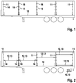
- Fig. 1 shows a side view of a semi-trailer with open side wall and fasteners 16 for connection with stiffening elements.
- Fig. 2 shows the same semi-trailer with open side wall and hinged stiffening elements 13.
- the stiffening elements 13 can be like the known Einstecklatten mounted at different heights and between different stanchions 11 to customize the semi-trailer to the cargo to be transported.
- the invention or the embodiment according to the invention offers the same functionalities as a known semi-trailer with slats.
- a single stiffening element 13 may be provided, as shown in the front 3 fields in the direction of travel.
- the stiffening elements 13 of adjacent fields can be arranged at the same height or at different heights.
- a plurality of stiffening elements 13 per field may be provided. It is, for example, possible that a stiffening element 13 in the area of the depot, so close to the ground, and another stiffening element 13 is stretched close to the roof.
- stanchions 11 are connected to the loading area 10 of the commercial vehicle body or the commercial vehicle.
- the stanchions 11 may be formed in a manner known per se.
- the middle stanchions can be hung movably on the roof racks in a known manner on rollers.
- the semi-trailer according to Fig. 2 belt-like, flexible stiffening elements 13.
- These stiffening elements are bands or straps made of textile materials, such as woven, knitted or braided. Such straps or straps are used in connection with cargo securing systems, for stiffening sunroofs or for securing tarpaulins to tarpaulins.
- stiffening elements 13 are characterized by the fact that they are on the one hand to train resilient and on the other hand so flexible that they can be rolled up or folded. Thus, the stiffening elements 13 can be used both as retaining elements, as well as in small containers, such as stowed in the tool box, as in Fig. 2 shown.
- the stiffening elements 13 each have two attachment ends 14, which are adapted to be connected to the attachment means 16 of the stanchions 11.
- the attachment ends 14 may be, for example, loops which are hooked into the fastening means 16 of the stanchions 11. Other attachment ends 14 are possible. As in Fig. 2 to see the attachment ends 14 are connected to the adjacent stanchions 11 tensile.
- the stiffening element 13 is stretched between the stanchions 11.
- a clamping device 15 is provided, which is inserted into the stiffening element 13 and whose length can shorten for clamping.
- suitable belt tensioner for example. Spannratschen or other means of application that can apply a clamping force between the two stanchions.
- the fastening means 16 for transmitting a tensile force to the stanchions 11 are in the example according to FIGS. 1, 2 designed as a hook.
- the fastening ends 14 of the stiffening elements 13 formed as loops engage in the hooks, so that both tensile forces in the longitudinal direction of the commercial vehicle body and transverse forces transversely to the longitudinal direction of the Commercial vehicle body can be transferred.
- Other fasteners 16, such as eyelets, rings or clip elements are possible.
- the fastening means 16 may be height adjustable.
- a belt-like, flexible stiffening element 13 for stiffening the side wall of a commercial vehicle body, in particular a tarpaulin structure is disclosed in which the retaining element between two stanchions 11 is arranged and connected thereto. The retaining element is stretched between the stanchions 11 such that lateral forces of the charge are transmitted from the stiffening element 13 to the stanchions 11.
- the stiffening element 13, in particular the webbing is attached as follows. First, the stiffening element 13 is mounted with a fastening end 14 in a fastening means 16 of a stanchion 11. Then the other attachment ends 14 is suspended in the adjacent Runge 11 accordingly. When the belt tensioner is open, the stiffening element 13 is pulled slightly taut. Then the belt tensioner is actuated, so that the stiffening element 13 is taut between the two stanchions 11.
Abstract
Die Erfindung betrifft einen Nutzfahrzeugaufbau, insbesondere Planenaufbau, mit einer Ladefläche (10) und Rungen (11), die mit der Ladefläche (10) verbunden sind, wobei wenigstens ein Rückhalteelement (12) zwischen zwei benachbarten Rungen (11) angeordnet ist und diese verbindet. Die Erfindung zeichnet sich daruch aus, dass das Rückhalteelement (12) ein gurtartiges, flexibles Aussteifungselement (13) umfasst, das auf Zug belastbar ist und zwei Befestigungsenden (14) aufweist, wobei die Befestigungsenden (14) mit den benachbarten Rungen (11) zugfest verbunden sind und das Aussteifungselement (13) zwischen den Rungen (11) gespannt ist.

Description
Die Erfindung betrifft einen Nutzfahrzeugaufbau, insbesondere einen Planenaufbau mit den Merkmalen des Oberbegriffs des Anspruchs 1. Die Erfindung betrifft ferner ein Nutzfahrzeug mit einem derartigen Aufbau. Ein Nutzfahrzeugaufbau der eingangs genannten Art ist beispielsweise aus
Einstecklatten aus Holz oder Aluminium werden üblicherweise bei Planensattelaufliegern verwendet, um Querkräfte der Ladung beispielsweise bei Kurvenfahrten aufzunehmen. Die Einstecklatten sind in Lattentaschen gehalten, die an den Rungen des Nutzfahrzeugaufbaus angebracht sind. Die Einstecklatten erstrecken sich im Gebrauch parallel zur Ladefläche und bilden Rückhalteelemente, die verhindern, dass die Ladung seitlich über die Ladefläche vorsteht oder von der Ladefläche fällt.Slats made of wood or aluminum are commonly used in tarp semitrailers to absorb lateral forces of the load, for example when cornering. The Einstecklatten are held in batten pockets, which are attached to the stanchions of the commercial vehicle body. The Einstecklatten extend in use parallel to the loading surface and form retaining elements, which prevent the load from projecting laterally over the loading area or falls from the loading area.
Einstecklatten sind sperrig und werden bei Nichtgebrauch seitlich unter der Ladefläche in sogenannten Lattenlagerungen aufbewahrt. Die Lattenlagerungen verhindern, dass andere Zubehörteile, zum Beispiel Palettenstaukästen problemlos montiert werden können bzw. überhaupt Platz finden. Bei den im Gebrauch weiter oben angeordneten Einstecklatten geht die Gefahr aus, dass diese aus den Plattentaschen herausfallen und den Fahrer verletzen. Die Mittelrungen sind üblicherweise auf Rollen gelagert und können sich etwas in Längsrichtung des Aufbaus verschieben. Da die Einstecklatten in den Lattentaschen lediglich aufliegen, können diese herabfallen, wenn der Abstand der Rungen, zwischen denen die Einstecklatten angeordnet sind, zu groß wird.Slats are bulky and are stored when not in use laterally under the cargo area in so-called lattenlagerungen. The latten bearings prevent other accessories, such as pallet storage boxes can be easily installed or even find space. With the insert slats arranged further up in use, there is a risk that they will fall out of the plate pockets and injure the driver. The Center stanchions are usually mounted on rollers and can move slightly in the longitudinal direction of the structure. Since the Einstecklatten only rest in the batten pockets, they can fall down when the distance of the stanchions between which the Einstecklatten are arranged, is too large.
Einstecklatten haben generell nur eine begrenzte Rückhaltefunktion, die von der Festigkeit der Einstecklatten abhängt. Die Elastizität bekannter Einstecklatten ist relativ gering. Bei Überbelastung knicken Einstecklatten ab, unabhängig davon, ob diese aus Aluminium oder Holz bestehen. Diese bieten dann keine Rückhaltefunktion, sondern können aus den Lattentaschen herausfallen.Slats generally have only a limited retention function, which depends on the strength of the Einstecklatten. The elasticity of known Einstecklatten is relatively low. When overloaded, slats crease, regardless of whether they are made of aluminum or wood. These then offer no retention function, but can fall out of the batten pockets.
Der Erfindung liegt die Aufgabe zu Grunde, den eingangs genannten Nutzfahrzeugaufbau dahingehend zu verbessern, dass das Rückhalteelement möglichst wenig Stauraum einnimmt, wenn dieses nicht gebraucht wird, und die Rückhaltefunktion optimiert wird. Der Erfindung liegt ferner die Aufgabe zu Grunde ein Nutzfahrzeug anzugeben.The invention is based on the object to improve the aforementioned commercial vehicle structure to the effect that the retaining element takes up as little storage space when it is not needed, and the retention function is optimized. The invention is further based on the object of specifying a commercial vehicle.
Erfindungsgemäß wird diese Aufgabe durch einen Nutzfahrzeugaufbau mit den Merkmalen des Anspruchs 1 gelöst. Mit Blick auf das Nutzfahrzeug wird die Aufgabe durch den Gegenstand des Anspruchs 8 gelöst.According to the invention this object is achieved by a commercial vehicle structure with the features of claim 1. With regard to the commercial vehicle, the object is achieved by the subject matter of claim 8.
Konkret wird die Aufgabe durch einen Nutzfahrzeugaufbau, insbesondere einen Planenaufbau mit einer Ladefläche und Rungen gelöst, die mit der Ladefläche verbunden sind. Wenigstens ein Rückhalteelement ist zwischen zwei benachbarten Rungen angeordnet. Das Rückhalteelement umfasst ein gurtartiges, flexibles Aussteifungselement, das auf Zug belastbar ist. Das Aussteifungselement weist zwei Befestigungsenden auf. Die Befestigungsenden sind mit den benachbarten Rungen zugfest verbunden. Das Aussteifungselement ist zwischen den Rungen gespannt.Specifically, the object is achieved by a commercial vehicle structure, in particular a tarpaulin structure with a loading area and stanchions, which are connected to the loading area. At least one retaining element is arranged between two adjacent stanchions. The retaining element comprises a belt-like, flexible stiffening element, which is loadable to train. The stiffening element has two attachment ends. The attachment ends are connected to the adjacent stanchions tensile strength. The stiffening element is stretched between the stanchions.
Die Erfindung hat mehrere Vorteile.The invention has several advantages.
Im Unterschied zur den starren Einstecklatten sind gurtartige, flexible Aussteifungselemente leicht, sodass eine höhere Zuladung möglich ist, da schwere Einstecklatten nicht mitgeführt werden müssen. Die flexiblen Aussteifungselemente lassen sich einfach verstauen. Beispielsweise können die Aussteifungselemente zusammengerollt und im Werkzeugkasten verstaut werden. Es versteht sich, dass die Aussteifungselemente lösbar mit den Rungen verbunden sind.In contrast to the rigid Einstecklatten belt-like, flexible stiffening elements are lightweight, so that a higher payload is possible because heavy Einstecklatten must not be carried. The flexible stiffeners are easy to stow away. For example, the stiffening elements can be rolled up and stowed in the toolbox. It is understood that the stiffening elements are releasably connected to the stanchions.
Die Rückhaltewirkung durch die gurtartigen, flexiblen Aussteifungselemente ist hervorragend, da die Aussteifungselemente im Vergleich zu starren Einstecklatten flexibler und elastischer sind. Die Knickgefahr entfällt daher. Außerdem ist der Rückstelleffekt deutlich besser als bei Einstecklatten, da die Aussteifungselemente elastischer als Einstecklatten sind und ähnlich wie ein Gummiband arbeiten.The retention effect by the belt-like, flexible stiffening elements is excellent, since the stiffening elements are more flexible and elastic compared to rigid Einstecklatten. The risk of buckling is therefore eliminated. In addition, the restoring effect is significantly better than slats, since the stiffening elements are more elastic than slats and work much like a rubber band.
Die Aussteifungselemente sind dazu auf Zug belastbar und weisen zwei Befestigungsenden auf. Die Befestigungsenden sind mit den benachbarten Rungen zugfest verbunden. Das Aussteifungselement ist zwischen den Rungen gespannt. Das gespannte Aussteifungselement nimmt Querkräfte auf, die er von der Ladung auf das Aussteifungselement ausgeübt wird. Die Querkräfte werden durch das gespannte Aussteifungselement auf die Rungen und von dort auf den Ladeboden übertragen.The stiffening elements are loaded on train and have two attachment ends. The attachment ends are connected to the adjacent stanchions tensile strength. The stiffening element is stretched between the stanchions. The tensioned stiffening element absorbs lateral forces exerted by the load on the stiffening element. The lateral forces are transmitted to the stanchions by the tensioned stiffening element and from there to the loading floor.
Im Unterschied zu den starren Einstecklatten ist das Aussteifungselement biegeelastisch und lässt sich verformen, so dass diese gut verstaut werden kann. Im montierten Zustand ist das Aussteifungselement auf Zug belastbar und kann zwischen den beiden Rungen gespannt werden.In contrast to the rigid Einstecklatten the stiffening element is flexible and can be deformed so that it can be stowed well. In the assembled state, the stiffening element can be loaded to train and can be stretched between the two stanchions.
Von dem Aussteifungselement geht eine sehr viel geringere Verletzungsgefahr als von Einstecklatten aus.From the stiffening element is a much lower risk of injury than from Einstecklatten.
Ein weiterer Vorteil der Erfindung besteht darin, dass der Nutzfahrzeugaufbau, insbesondere der Planenaufbau insgesamt im Vergleich zu bekannten Aufbauten stabilisiert wird, da die Aussteifungselemente die Rungen, insbesondere die Eckrungen und die Mittelrungen miteinander verspannen. Im Unterschied dazu werden die bekannten Einstecklatten in die Lattentaschen lediglich eingelegt. Es erfolgt kein Kraftschluss in Längsrichtung des Ladebodens bzw. des Aufbaus.Another advantage of the invention is that the commercial vehicle structure, in particular the tarpaulin structure is stabilized in total compared to known structures, since the stiffening elements brace the stanchions, in particular the Eckrungen and the middle stakes with each other. In contrast, the known Einstecklatten are only inserted into the batten pockets. There is no adhesion in the longitudinal direction of the loading floor or the structure.
Es versteht sich, dass im Prinzip ein einziges Aussteifungselement zwischen zwei Rungen vorgesehen sein kann. In der Praxis sind jedoch üblicherweise mehrere Aussteifungselemente zwischen zwei Rungen bzw. mehrere Aussteifungselemente im Aufbau vorgesehen.It is understood that, in principle, a single stiffening element can be provided between two stanchions. In practice, however, usually a plurality of stiffening elements between two stanchions or more stiffening elements are provided in the structure.
Die Aussteifungselemente ersetzen die bekannten Einstecklatten, sodass eine entsprechende Anzahl von Aussteifungselementen vorgesehen ist.The stiffening replace the known Einstecklatten, so that a corresponding number of stiffening elements is provided.
Bevorzugte Ausführungsformen der Erfindung sind in den Unteransprüchen angegeben.Preferred embodiments of the invention are specified in the subclaims.
Das Aussteifungselement kann einen Gurt bzw. ein Gurtband oder ein Seil oder eine Kette umfassen. Besonders bevorzugt sind Gurte, da diese zugfest sind und klein zusammengerollt werden können. Die Erfindung funktioniert auch mit Seilen oder Ketten, die jeweils Zugkräfte übertragen können.The stiffening element may comprise a belt or a webbing or a rope or a chain. Particularly preferred are straps, as they are tensile and can be rolled up small. The invention also works with ropes or chains, each of which can transmit tensile forces.
Vorzugsweise weist das Aussteifungselement eine Spanneinrichtung zum Aufbringen einer Spannkraft zwischen den beiden Rungen auf. Dadurch kann auf einfache Weise die zwischen zwei Rungen erforderliche Spannung des Aussteifungselements erzeugt werden. Die Spanneinrichtung kann beispielsweise eine Spannratsche, ein Kniehebel, ein Schnellspannelement oder eine Aufrollmechanik mit automatischer Verriegelung sein.Preferably, the stiffening element has a clamping device for applying a clamping force between the two stanchions. As a result, the required between two stanchions stress of the stiffening element can be generated in a simple manner. The tensioning device can be, for example, a tensioning ratchet, a toggle lever, a quick-action clamping element or a retracting mechanism with automatic locking.
Bei einer bevorzugten Ausführungsform weisen die Rungen Befestigungsmittel zur Übertragung einer Zugkraft vom Aussteifungselement auf die Rungen auf. Das Befestigungsmittel zeichnet sich dadurch aus, dass dieses zur Übertragung von Zugkräften geeignet ist, die in einer Richtung entlang der Längsachse des Aufbaus wirken, wenn das Aussteifungselement zwischen den Rungen gespannt ist. Die Befestigungsmittel können auch Kräfte aufnehmen, die senkrecht zur Längsachse des Aufbaus wirken, wenn Querkräfte auftreten, die von der Ladung auf das Aussteifungselement beispielsweise bei Kurvenfahrten wirken.In a preferred embodiment, the stanchions have attachment means for transmitting a tensile force from the stiffening member to the stanchions. The fastening means is characterized in that it is suitable for transmitting tensile forces acting in a direction along the longitudinal axis of the structure when the stiffening element is stretched between the stanchions. The fasteners may also receive forces that are perpendicular to the longitudinal axis of the structure when transverse forces occur that act on the stiffener from the load, for example when cornering.
Die Befestigungsmittel sind dazu vorgesehen, mit den Befestigungsenden des Aussteifungselements verbunden zu werden, insbesondere lösbar verbunden zu werden.The fastening means are intended to be connected to the attachment ends of the stiffening element, in particular to be releasably connected.
Die Befestigungsmittel können Haken, Ösen, Ringe oder Clipelemente umfassen. Haken haben den Vorteil, dass diese mit entsprechenden Schlaufen der Aussteifungselemente einfach und schnell verbunden und von diesen gelöst werden können.The fastening means may comprise hooks, eyes, rings or clip elements. Hooks have the advantage that they can be easily and quickly connected with corresponding loops of the stiffening elements and released from them.
Bei einer besonders bevorzugten Ausführungsform sind die Befestigungsmittel an den Rungen höhenverstellbar befestigt. Dies kann beispielsweise durch ein Lochmuster erfolgen, das in den Rungen ausgebildet ist.In a particularly preferred embodiment, the fastening means are attached to the stakes adjustable in height. This can be done for example by a hole pattern formed in the stanchions.
Die Erfindung wird nachstehend anhand eines Ausführungsbeispiels unter Bezug auf die beigefügten schematischen Zeichnungen mit weiteren Einzelheiten näher erläutert.The invention will be explained in more detail below with reference to an embodiment with reference to the accompanying diagrammatic drawings with further details.
In diesen zeigen
- Fig. 1
- eine Seitenansicht eines Sattelaufliegers mit geöffneter Seitenwand nach einem erfindungsgemäßen Ausführungsbeispiel; und
- Fig. 2
- den Sattelauflieger gemäß
Fig. 1 mit gurtartigen Aussteifungselementen.
- Fig. 1
- a side view of a semi-trailer with open side wall according to an embodiment of the invention; and
- Fig. 2
- the semi-trailer according to
Fig. 1 with belt-like stiffening elements.
Zwischen benachbarten Rungen 11 kann ein einziges Aussteifungselement 13 vorgesehen sein, wie in den in Fahrtrichtung vorderen 3 Feldern gezeigt. Die Aussteifungselemente 13 benachbarter Felder können auf derselben Höhe oder auf unterschiedlichen Höhen angeordnet sein. Wie im vierten Feld gezeigt, können mehrere Aussteifungselemente 13 pro Feld vorgesehen sein. Es ist bspw. möglich, dass ein Aussteifungselement 13 im Bereich des Depots, also bodennah, und ein weiteres Aussteifungselement 13 dachnah gespannt ist.Between
Wie in den
Anstelle der bekannten Einstecklatten weist der Sattelauflieger gemäß
Andere flexible Aussteifungselemente, wie beispielsweise Seile, insbesondere Stahlseile oder Ketten sind möglich. Die Aussteifungselemente 13 zeichnen sich dadurch aus, dass diese einerseits auf Zug belastbar und andererseits so flexibel sind, dass diese zusammengerollt oder zusammengelegt werden können. Dadurch können die Aussteifungselemente 13 sowohl als Rückhalteelemente eingesetzt, als auch in kleinen Behältern, wie beispielsweise im Werkzeugkasten verstaut werden, wie in
Die Aussteifungselemente 13 weisen jeweils zwei Befestigungsenden 14 auf, die dazu geeignet sind, mit den Befestigungsmitteln 16 der Rungen 11 verbunden zu werden. Die Befestigungsenden 14 können beispielsweise Schlaufen sein, die in die Befestigungsmittel 16 der Rungen 11 eingehängt werden. Andere Befestigungsenden 14 sind möglich. Wie in
Das Aussteifungselement 13 ist zwischen den Rungen 11 gespannt. Dazu ist eine Spanneinrichtung 15 vorgesehen, die in das Aussteifungselement 13 eingefügt ist und dessen Länge zum Spannen verkürzen kann. Hierfür bekommen geeignete Gurtspanner, bspw. Spannratschen oder andere Mittel zur Anwendung, die eine Spannkraft zwischen den beiden Rungen aufbringen können.The stiffening element 13 is stretched between the
Die Befestigungsmittel 16 zur Übertragung einer Zugkraft auf die Rungen 11 sind im Beispiel gemäß
Die Befestigungsmittel 16 können höhenverstellbar sein.The fastening means 16 may be height adjustable.
Im Rahmen der Erfindung wird die Verwendung eines gurtartigen, flexiblen Aussteifungselement 13 zum Aussteifen der Seitenwand eines Nutzfahrzeugaufbaus, insbesondere eines Planenaufbau offenbart, bei der das Rückhalteelement zwischen zwei Rungen 11 angeordnet und mit diesen verbunden ist. Das Rückhalteelement ist zwischen den Rungen 11 derart gespannt, dass Querkräfte der Ladung vom Aussteifungselement 13 auf die Rungen 11 übertragen werden.In the context of the invention, the use of a belt-like, flexible stiffening element 13 for stiffening the side wall of a commercial vehicle body, in particular a tarpaulin structure is disclosed in which the retaining element between two
Im Gebrauch wird das Aussteifungselement 13, insbesondere das Gurtband wie folgt angebracht. Zunächst wird das Aussteifungselement 13 mit einem Befestigungsende 14 in ein Befestigungsmittel 16 einer Runge 11 eingehängt. Dann wird das andere Befestigungsenden 14 in die benachbarte Runge 11 entsprechend eingehängt. Bei geöffnetem Gurtspanner wird das Aussteifungselement 13 leicht straffgezogen. Dann wird der Gurtspanner betätigt, sodass das Aussteifungselement 13 straff zwischen den beiden Rungen 11 gespannt ist.In use, the stiffening element 13, in particular the webbing is attached as follows. First, the stiffening element 13 is mounted with a
- 1010
- Ladeflächeload area
- 1111
- Rungenconclusions
- 1212
- RückhalteelementRetaining element
- 1313
- flexibles Aussteifungselementflexible stiffening element
- 1414
- Befestigungsendenfixing ends
- 1515
- Spanneinrichtungtensioning device
- 1616
- Befestigungsmittelfastener
Claims (8)
dadurch gekennzeichnet, dass
das Rückhalteelement (12) ein gurtartiges, flexibles Aussteifungselement (13) umfasst, das auf Zug belastbar ist und zwei Befestigungsenden (14) aufweist, wobei die Befestigungsenden (14) mit den benachbarten Rungen (11) zugfest verbunden sind und das Aussteifungselement (13) zwischen den Rungen (11) gespannt ist.Commercial vehicle construction, in particular tarpaulin construction, with a loading area (10) and stanchions (11) which are connected to the loading area (10), wherein at least one retaining element (12) is arranged between and connects two adjacent stanchions (11),
characterized in that
the retaining element (12) comprises a belt-like, flexible stiffening element (13) which can be loaded in tension and has two fastening ends (14), the fastening ends (14) being connected in a tension-proof manner to the adjacent stanchions (11) and the stiffening element (13) between the stakes (11) is stretched.
dadurch gekennzeichnet, dass
das Aussteifungselement (13) einen Gurt oder ein Seil oder eine Kette umfasst.Commercial vehicle body according to claim 1
characterized in that
the stiffening element (13) comprises a belt or a rope or a chain.
dadurch gekennzeichnet, dass
das Aussteifungselement (13) eine Spanneinrichtung (15) zum Aufbringen einer Spannkraft zwischen den beiden Rungen (11) aufweist.Commercial vehicle body according to claim 1 or 2
characterized in that
the stiffening element (13) has a clamping device (15) for applying a clamping force between the two stanchions (11).
dadurch gekennzeichnet, dass
die Spanneinrichtung (15) eine Spannratsche, einen Kniehebel, ein Schnellspannelement oder eine Aufrollmechanik mit automatischer Verriegelung umfasst.Commercial vehicle body according to claim 3
characterized in that s
the tensioning device (15) comprises a tensioning ratchet, a toggle lever, a quick-action clamping element or a retraction mechanism with automatic locking.
dadurch gekennzeichnet, dass
die Rungen (11) Befestigungsmittel (16) zur Übertragung einer Zugkraft vom Aussteifungselement (13) auf die Rungen (11) aufweisen.Commercial vehicle body according to one of the preceding claims
characterized in that
the stanchions (11) have fastening means (16) for transmitting a tensile force from the stiffening element (13) to the stanchions (11).
dadurch gekennzeichnet, dass
die Befestigungsmittel (16) Haken, Ösen, Ringe oder Clipelemente umfassen.Commercial vehicle body according to claim 5
characterized in that
the fastening means (16) comprise hooks, eyes, rings or clip elements.
dadurch gekennzeichnet, dass
die Befestigungsmittel (16) an den Rungen (11) höhenverstellbar befestigt sind.Commercial vehicle body according to claim 5 or 6
characterized in that
the fastening means (16) on the stanchions (11) are mounted vertically adjustable.
Applications Claiming Priority (1)
| Application Number | Priority Date | Filing Date | Title |
|---|---|---|---|
| DE202018101637.7U DE202018101637U1 (en) | 2018-03-23 | 2018-03-23 | Commercial vehicle body and commercial vehicle |
Publications (3)
| Publication Number | Publication Date |
|---|---|
| EP3543052A1 true EP3543052A1 (en) | 2019-09-25 |
| EP3543052B1 EP3543052B1 (en) | 2023-11-22 |
| EP3543052C0 EP3543052C0 (en) | 2023-11-22 |
Family
ID=65801937
Family Applications (1)
| Application Number | Title | Priority Date | Filing Date |
|---|---|---|---|
| EP19162410.5A Active EP3543052B1 (en) | 2018-03-23 | 2019-03-13 | Commercial vehicle structure and commercial vehicle |
Country Status (2)
| Country | Link |
|---|---|
| EP (1) | EP3543052B1 (en) |
| DE (1) | DE202018101637U1 (en) |
Citations (3)
| Publication number | Priority date | Publication date | Assignee | Title |
|---|---|---|---|---|
| DE102007037294A1 (en) | 2007-08-07 | 2009-02-19 | Kögel Fahrzeugwerke GmbH | Device for load protection in commercial motor vehicles, particularly road semi-trailer, has profile latch arranged in longitudinal direction of commercial motor vehicle and is detachably connected with vehicle frame |
| WO2013164450A1 (en) * | 2012-05-03 | 2013-11-07 | Westdeutscher Drahtseil-Verkauf Dolezych Gmbh & Co. Kg | Transport vehicle |
| DE202011110506U1 (en) * | 2011-10-27 | 2014-07-08 | Fahrzeugwerk Bernard Krone Gmbh | Vehicle body for the transport of bulk or stackable goods |
Family Cites Families (2)
| Publication number | Priority date | Publication date | Assignee | Title |
|---|---|---|---|---|
| DE202011005008U1 (en) * | 2011-04-07 | 2011-08-08 | Günter Alberth | Multi-Safe |
| DE102015112843B4 (en) * | 2015-08-05 | 2021-01-28 | Kögel Trailer GmbH | Post for a commercial vehicle superstructure as well as a load securing system, commercial vehicle body and commercial vehicle with such a post |
-
2018
- 2018-03-23 DE DE202018101637.7U patent/DE202018101637U1/en active Active
-
2019
- 2019-03-13 EP EP19162410.5A patent/EP3543052B1/en active Active
Patent Citations (3)
| Publication number | Priority date | Publication date | Assignee | Title |
|---|---|---|---|---|
| DE102007037294A1 (en) | 2007-08-07 | 2009-02-19 | Kögel Fahrzeugwerke GmbH | Device for load protection in commercial motor vehicles, particularly road semi-trailer, has profile latch arranged in longitudinal direction of commercial motor vehicle and is detachably connected with vehicle frame |
| DE202011110506U1 (en) * | 2011-10-27 | 2014-07-08 | Fahrzeugwerk Bernard Krone Gmbh | Vehicle body for the transport of bulk or stackable goods |
| WO2013164450A1 (en) * | 2012-05-03 | 2013-11-07 | Westdeutscher Drahtseil-Verkauf Dolezych Gmbh & Co. Kg | Transport vehicle |
Also Published As
| Publication number | Publication date |
|---|---|
| EP3543052B1 (en) | 2023-11-22 |
| DE202018101637U1 (en) | 2019-06-27 |
| EP3543052C0 (en) | 2023-11-22 |
Similar Documents
| Publication | Publication Date | Title |
|---|---|---|
| DE102015004326B3 (en) | Vehicle for the transport of bulk and / or general cargo | |
| DE202008016326U1 (en) | Device for securing cargo | |
| DE10138771B4 (en) | System for securing a load | |
| DE19756865A1 (en) | Truck superstructure | |
| DE102017001675A1 (en) | Tarpaulin with elastic reinforcing straps and securing elements | |
| EP2330020B1 (en) | Side covering of a commercial vehicle structure | |
| DE102015108782B4 (en) | Vehicle body, in particular for commercial vehicles, commercial vehicle with such a vehicle body and manufacturing method | |
| DE102008011704B4 (en) | Arrangement and method for securing cargo as well as commercial vehicle with such an arrangement | |
| DE69725164T2 (en) | LASTENING SYSTEM AND METHOD FOR HOLDING LOADS | |
| EP3243678B1 (en) | Commercial vehicle structure | |
| EP3543052A1 (en) | Commercial vehicle structure and commercial vehicle | |
| EP3015311B1 (en) | Commercial vehicle structure and method for securing the position of an item transported on a transport platform of a commercial vehicle | |
| EP3810459B1 (en) | Flat securing means | |
| DE102013009103B4 (en) | Vehicle body with frame and tarpaulin as well as vehicle with the vehicle body | |
| DE102010035194A1 (en) | Device for securing cargo of e.g. passenger car, against forces caused during transport movement, has holding structure arranged on displaceable support around load under tensile stress, where holding structure is linked at support | |
| DE202016102046U1 (en) | Lashing strap for securing cargo | |
| WO2016116235A1 (en) | Transport vehicle | |
| EP3666567B1 (en) | Side curtain for a truck-trailer, truck-trailer and truck with a truck-trailer | |
| DE102020134925B3 (en) | Tarpaulin and commercial vehicle with such a tarpaulin | |
| DE102010045524A1 (en) | Fastening device for a tarpaulin structure of a commercial vehicle, commercial vehicle body and commercial vehicle with such a fastening device | |
| DE102019119131B4 (en) | separation net | |
| EP3623219B1 (en) | Profile for securing a load and loading area for receiving cargo | |
| EP3512726B1 (en) | Tensioning device and load securing system | |
| DE10241108A1 (en) | Flexible securing system for loads on transport lorries has cord hanging free at one end near loading opening and running up and over lift devices and secured at other opposite end | |
| DE102022115254A1 (en) | Lashing device for securing partial loads in the direction of travel of a commercial vehicle body, load securing system and commercial vehicle body with such a lashing device |
Legal Events
| Date | Code | Title | Description |
|---|---|---|---|
| PUAI | Public reference made under article 153(3) epc to a published international application that has entered the european phase |
Free format text: ORIGINAL CODE: 0009012 |
|
| STAA | Information on the status of an ep patent application or granted ep patent |
Free format text: STATUS: THE APPLICATION HAS BEEN PUBLISHED |
|
| AK | Designated contracting states |
Kind code of ref document: A1 Designated state(s): AL AT BE BG CH CY CZ DE DK EE ES FI FR GB GR HR HU IE IS IT LI LT LU LV MC MK MT NL NO PL PT RO RS SE SI SK SM TR |
|
| AX | Request for extension of the european patent |
Extension state: BA ME |
|
| STAA | Information on the status of an ep patent application or granted ep patent |
Free format text: STATUS: REQUEST FOR EXAMINATION WAS MADE |
|
| 17P | Request for examination filed |
Effective date: 20191010 |
|
| RBV | Designated contracting states (corrected) |
Designated state(s): AL AT BE BG CH CY CZ DE DK EE ES FI FR GB GR HR HU IE IS IT LI LT LU LV MC MK MT NL NO PL PT RO RS SE SI SK SM TR |
|
| STAA | Information on the status of an ep patent application or granted ep patent |
Free format text: STATUS: EXAMINATION IS IN PROGRESS |
|
| 17Q | First examination report despatched |
Effective date: 20200716 |
|
| STAA | Information on the status of an ep patent application or granted ep patent |
Free format text: STATUS: EXAMINATION IS IN PROGRESS |
|
| GRAP | Despatch of communication of intention to grant a patent |
Free format text: ORIGINAL CODE: EPIDOSNIGR1 |
|
| STAA | Information on the status of an ep patent application or granted ep patent |
Free format text: STATUS: GRANT OF PATENT IS INTENDED |
|
| INTG | Intention to grant announced |
Effective date: 20230602 |
|
| GRAS | Grant fee paid |
Free format text: ORIGINAL CODE: EPIDOSNIGR3 |
|
| GRAA | (expected) grant |
Free format text: ORIGINAL CODE: 0009210 |
|
| STAA | Information on the status of an ep patent application or granted ep patent |
Free format text: STATUS: THE PATENT HAS BEEN GRANTED |
|
| AK | Designated contracting states |
Kind code of ref document: B1 Designated state(s): AL AT BE BG CH CY CZ DE DK EE ES FI FR GB GR HR HU IE IS IT LI LT LU LV MC MK MT NL NO PL PT RO RS SE SI SK SM TR |
|
| REG | Reference to a national code |
Ref country code: GB Ref legal event code: FG4D Free format text: NOT ENGLISH |
|
| REG | Reference to a national code |
Ref country code: CH Ref legal event code: EP |
|
| REG | Reference to a national code |
Ref country code: DE Ref legal event code: R096 Ref document number: 502019009952 Country of ref document: DE |
|
| REG | Reference to a national code |
Ref country code: IE Ref legal event code: FG4D Free format text: LANGUAGE OF EP DOCUMENT: GERMAN |
|
| U01 | Request for unitary effect filed |
Effective date: 20231221 |
|
| U07 | Unitary effect registered |
Designated state(s): AT BE BG DE DK EE FI FR IT LT LU LV MT NL PT SE SI Effective date: 20240108 |
|
| U20 | Renewal fee paid [unitary effect] |
Year of fee payment: 6 Effective date: 20240228 |
|
| PG25 | Lapsed in a contracting state [announced via postgrant information from national office to epo] |
Ref country code: GR Free format text: LAPSE BECAUSE OF FAILURE TO SUBMIT A TRANSLATION OF THE DESCRIPTION OR TO PAY THE FEE WITHIN THE PRESCRIBED TIME-LIMIT Effective date: 20240223 |
|
| PG25 | Lapsed in a contracting state [announced via postgrant information from national office to epo] |
Ref country code: IS Free format text: LAPSE BECAUSE OF FAILURE TO SUBMIT A TRANSLATION OF THE DESCRIPTION OR TO PAY THE FEE WITHIN THE PRESCRIBED TIME-LIMIT Effective date: 20240322 |
|
| PG25 | Lapsed in a contracting state [announced via postgrant information from national office to epo] |
Ref country code: ES Free format text: LAPSE BECAUSE OF FAILURE TO SUBMIT A TRANSLATION OF THE DESCRIPTION OR TO PAY THE FEE WITHIN THE PRESCRIBED TIME-LIMIT Effective date: 20231122 |
|
| PG25 | Lapsed in a contracting state [announced via postgrant information from national office to epo] |
Ref country code: IS Free format text: LAPSE BECAUSE OF FAILURE TO SUBMIT A TRANSLATION OF THE DESCRIPTION OR TO PAY THE FEE WITHIN THE PRESCRIBED TIME-LIMIT Effective date: 20240322 Ref country code: GR Free format text: LAPSE BECAUSE OF FAILURE TO SUBMIT A TRANSLATION OF THE DESCRIPTION OR TO PAY THE FEE WITHIN THE PRESCRIBED TIME-LIMIT Effective date: 20240223 Ref country code: ES Free format text: LAPSE BECAUSE OF FAILURE TO SUBMIT A TRANSLATION OF THE DESCRIPTION OR TO PAY THE FEE WITHIN THE PRESCRIBED TIME-LIMIT Effective date: 20231122 |