EP3542996B1 - Verfahren für die bearbeitung eines rahmens oder teilrahmens - Google Patents
Verfahren für die bearbeitung eines rahmens oder teilrahmens Download PDFInfo
- Publication number
- EP3542996B1 EP3542996B1 EP19163672.9A EP19163672A EP3542996B1 EP 3542996 B1 EP3542996 B1 EP 3542996B1 EP 19163672 A EP19163672 A EP 19163672A EP 3542996 B1 EP3542996 B1 EP 3542996B1
- Authority
- EP
- European Patent Office
- Prior art keywords
- abutting edge
- pressure body
- profile
- plastic profiles
- abutting
- Prior art date
- Legal status (The legal status is an assumption and is not a legal conclusion. Google has not performed a legal analysis and makes no representation as to the accuracy of the status listed.)
- Active
Links
Images



Classifications
-
- E—FIXED CONSTRUCTIONS
- E06—DOORS, WINDOWS, SHUTTERS, OR ROLLER BLINDS IN GENERAL; LADDERS
- E06B—FIXED OR MOVABLE CLOSURES FOR OPENINGS IN BUILDINGS, VEHICLES, FENCES OR LIKE ENCLOSURES IN GENERAL, e.g. DOORS, WINDOWS, BLINDS, GATES
- E06B3/00—Window sashes, door leaves, or like elements for closing wall or like openings; Layout of fixed or moving closures, e.g. windows in wall or like openings; Features of rigidly-mounted outer frames relating to the mounting of wing frames
- E06B3/96—Corner joints or edge joints for windows, doors, or the like frames or wings
- E06B3/9604—Welded or soldered joints
- E06B3/9608—Mitre joints
-
- B—PERFORMING OPERATIONS; TRANSPORTING
- B29—WORKING OF PLASTICS; WORKING OF SUBSTANCES IN A PLASTIC STATE IN GENERAL
- B29C—SHAPING OR JOINING OF PLASTICS; SHAPING OF MATERIAL IN A PLASTIC STATE, NOT OTHERWISE PROVIDED FOR; AFTER-TREATMENT OF THE SHAPED PRODUCTS, e.g. REPAIRING
- B29C37/00—Component parts, details, accessories or auxiliary operations, not covered by group B29C33/00 or B29C35/00
- B29C37/02—Deburring or deflashing
- B29C37/04—Deburring or deflashing of welded articles, e.g. deburring or deflashing in combination with welding
-
- B—PERFORMING OPERATIONS; TRANSPORTING
- B29—WORKING OF PLASTICS; WORKING OF SUBSTANCES IN A PLASTIC STATE IN GENERAL
- B29C—SHAPING OR JOINING OF PLASTICS; SHAPING OF MATERIAL IN A PLASTIC STATE, NOT OTHERWISE PROVIDED FOR; AFTER-TREATMENT OF THE SHAPED PRODUCTS, e.g. REPAIRING
- B29C65/00—Joining or sealing of preformed parts, e.g. welding of plastics materials; Apparatus therefor
- B29C65/02—Joining or sealing of preformed parts, e.g. welding of plastics materials; Apparatus therefor by heating, with or without pressure
-
- B—PERFORMING OPERATIONS; TRANSPORTING
- B29—WORKING OF PLASTICS; WORKING OF SUBSTANCES IN A PLASTIC STATE IN GENERAL
- B29C—SHAPING OR JOINING OF PLASTICS; SHAPING OF MATERIAL IN A PLASTIC STATE, NOT OTHERWISE PROVIDED FOR; AFTER-TREATMENT OF THE SHAPED PRODUCTS, e.g. REPAIRING
- B29C65/00—Joining or sealing of preformed parts, e.g. welding of plastics materials; Apparatus therefor
- B29C65/48—Joining or sealing of preformed parts, e.g. welding of plastics materials; Apparatus therefor using adhesives, i.e. using supplementary joining material; solvent bonding
-
- B—PERFORMING OPERATIONS; TRANSPORTING
- B29—WORKING OF PLASTICS; WORKING OF SUBSTANCES IN A PLASTIC STATE IN GENERAL
- B29C—SHAPING OR JOINING OF PLASTICS; SHAPING OF MATERIAL IN A PLASTIC STATE, NOT OTHERWISE PROVIDED FOR; AFTER-TREATMENT OF THE SHAPED PRODUCTS, e.g. REPAIRING
- B29C66/00—General aspects of processes or apparatus for joining preformed parts
- B29C66/01—General aspects dealing with the joint area or with the area to be joined
- B29C66/05—Particular design of joint configurations
- B29C66/10—Particular design of joint configurations particular design of the joint cross-sections
- B29C66/11—Joint cross-sections comprising a single joint-segment, i.e. one of the parts to be joined comprising a single joint-segment in the joint cross-section
- B29C66/116—Single bevelled joints, i.e. one of the parts to be joined being bevelled in the joint area
- B29C66/1162—Single bevel to bevel joints, e.g. mitre joints
-
- B—PERFORMING OPERATIONS; TRANSPORTING
- B29—WORKING OF PLASTICS; WORKING OF SUBSTANCES IN A PLASTIC STATE IN GENERAL
- B29C—SHAPING OR JOINING OF PLASTICS; SHAPING OF MATERIAL IN A PLASTIC STATE, NOT OTHERWISE PROVIDED FOR; AFTER-TREATMENT OF THE SHAPED PRODUCTS, e.g. REPAIRING
- B29C66/00—General aspects of processes or apparatus for joining preformed parts
- B29C66/01—General aspects dealing with the joint area or with the area to be joined
- B29C66/32—Measures for keeping the burr form under control; Avoiding burr formation; Shaping the burr
- B29C66/326—Shaping the burr, e.g. by the joining tool
- B29C66/3262—Shaping the burr, e.g. by the joining tool as after-treatment, e.g. by a separate tool
-
- B—PERFORMING OPERATIONS; TRANSPORTING
- B29—WORKING OF PLASTICS; WORKING OF SUBSTANCES IN A PLASTIC STATE IN GENERAL
- B29C—SHAPING OR JOINING OF PLASTICS; SHAPING OF MATERIAL IN A PLASTIC STATE, NOT OTHERWISE PROVIDED FOR; AFTER-TREATMENT OF THE SHAPED PRODUCTS, e.g. REPAIRING
- B29C66/00—General aspects of processes or apparatus for joining preformed parts
- B29C66/50—General aspects of joining tubular articles; General aspects of joining long products, i.e. bars or profiled elements; General aspects of joining single elements to tubular articles, hollow articles or bars; General aspects of joining several hollow-preforms to form hollow or tubular articles
- B29C66/51—Joining tubular articles, profiled elements or bars; Joining single elements to tubular articles, hollow articles or bars; Joining several hollow-preforms to form hollow or tubular articles
- B29C66/52—Joining tubular articles, bars or profiled elements
- B29C66/524—Joining profiled elements
- B29C66/5243—Joining profiled elements for forming corner connections, e.g. for making window frames or V-shaped pieces
- B29C66/52431—Joining profiled elements for forming corner connections, e.g. for making window frames or V-shaped pieces with a right angle, e.g. for making L-shaped pieces
-
- B—PERFORMING OPERATIONS; TRANSPORTING
- B29—WORKING OF PLASTICS; WORKING OF SUBSTANCES IN A PLASTIC STATE IN GENERAL
- B29C—SHAPING OR JOINING OF PLASTICS; SHAPING OF MATERIAL IN A PLASTIC STATE, NOT OTHERWISE PROVIDED FOR; AFTER-TREATMENT OF THE SHAPED PRODUCTS, e.g. REPAIRING
- B29C66/00—General aspects of processes or apparatus for joining preformed parts
- B29C66/70—General aspects of processes or apparatus for joining preformed parts characterised by the composition, physical properties or the structure of the material of the parts to be joined; Joining with non-plastics material
- B29C66/72—General aspects of processes or apparatus for joining preformed parts characterised by the composition, physical properties or the structure of the material of the parts to be joined; Joining with non-plastics material characterised by the structure of the material of the parts to be joined
- B29C66/725—General aspects of processes or apparatus for joining preformed parts characterised by the composition, physical properties or the structure of the material of the parts to be joined; Joining with non-plastics material characterised by the structure of the material of the parts to be joined being hollow-walled or honeycombs
- B29C66/7252—General aspects of processes or apparatus for joining preformed parts characterised by the composition, physical properties or the structure of the material of the parts to be joined; Joining with non-plastics material characterised by the structure of the material of the parts to be joined being hollow-walled or honeycombs hollow-walled
- B29C66/72523—General aspects of processes or apparatus for joining preformed parts characterised by the composition, physical properties or the structure of the material of the parts to be joined; Joining with non-plastics material characterised by the structure of the material of the parts to be joined being hollow-walled or honeycombs hollow-walled multi-channelled or multi-tubular
-
- B—PERFORMING OPERATIONS; TRANSPORTING
- B29—WORKING OF PLASTICS; WORKING OF SUBSTANCES IN A PLASTIC STATE IN GENERAL
- B29C—SHAPING OR JOINING OF PLASTICS; SHAPING OF MATERIAL IN A PLASTIC STATE, NOT OTHERWISE PROVIDED FOR; AFTER-TREATMENT OF THE SHAPED PRODUCTS, e.g. REPAIRING
- B29C66/00—General aspects of processes or apparatus for joining preformed parts
- B29C66/70—General aspects of processes or apparatus for joining preformed parts characterised by the composition, physical properties or the structure of the material of the parts to be joined; Joining with non-plastics material
- B29C66/73—General aspects of processes or apparatus for joining preformed parts characterised by the composition, physical properties or the structure of the material of the parts to be joined; Joining with non-plastics material characterised by the intensive physical properties of the material of the parts to be joined, by the optical properties of the material of the parts to be joined, by the extensive physical properties of the parts to be joined, by the state of the material of the parts to be joined or by the material of the parts to be joined being a thermoplastic or a thermoset
- B29C66/739—General aspects of processes or apparatus for joining preformed parts characterised by the composition, physical properties or the structure of the material of the parts to be joined; Joining with non-plastics material characterised by the intensive physical properties of the material of the parts to be joined, by the optical properties of the material of the parts to be joined, by the extensive physical properties of the parts to be joined, by the state of the material of the parts to be joined or by the material of the parts to be joined being a thermoplastic or a thermoset characterised by the material of the parts to be joined being a thermoplastic or a thermoset
- B29C66/7392—General aspects of processes or apparatus for joining preformed parts characterised by the composition, physical properties or the structure of the material of the parts to be joined; Joining with non-plastics material characterised by the intensive physical properties of the material of the parts to be joined, by the optical properties of the material of the parts to be joined, by the extensive physical properties of the parts to be joined, by the state of the material of the parts to be joined or by the material of the parts to be joined being a thermoplastic or a thermoset characterised by the material of the parts to be joined being a thermoplastic or a thermoset characterised by the material of at least one of the parts being a thermoplastic
- B29C66/73921—General aspects of processes or apparatus for joining preformed parts characterised by the composition, physical properties or the structure of the material of the parts to be joined; Joining with non-plastics material characterised by the intensive physical properties of the material of the parts to be joined, by the optical properties of the material of the parts to be joined, by the extensive physical properties of the parts to be joined, by the state of the material of the parts to be joined or by the material of the parts to be joined being a thermoplastic or a thermoset characterised by the material of the parts to be joined being a thermoplastic or a thermoset characterised by the material of at least one of the parts being a thermoplastic characterised by the materials of both parts being thermoplastics
-
- B—PERFORMING OPERATIONS; TRANSPORTING
- B29—WORKING OF PLASTICS; WORKING OF SUBSTANCES IN A PLASTIC STATE IN GENERAL
- B29C—SHAPING OR JOINING OF PLASTICS; SHAPING OF MATERIAL IN A PLASTIC STATE, NOT OTHERWISE PROVIDED FOR; AFTER-TREATMENT OF THE SHAPED PRODUCTS, e.g. REPAIRING
- B29C65/00—Joining or sealing of preformed parts, e.g. welding of plastics materials; Apparatus therefor
- B29C65/02—Joining or sealing of preformed parts, e.g. welding of plastics materials; Apparatus therefor by heating, with or without pressure
- B29C65/14—Joining or sealing of preformed parts, e.g. welding of plastics materials; Apparatus therefor by heating, with or without pressure using wave energy, i.e. electromagnetic radiation, or particle radiation
- B29C65/1403—Joining or sealing of preformed parts, e.g. welding of plastics materials; Apparatus therefor by heating, with or without pressure using wave energy, i.e. electromagnetic radiation, or particle radiation characterised by the type of electromagnetic or particle radiation
- B29C65/1412—Infrared [IR] radiation
-
- B—PERFORMING OPERATIONS; TRANSPORTING
- B29—WORKING OF PLASTICS; WORKING OF SUBSTANCES IN A PLASTIC STATE IN GENERAL
- B29C—SHAPING OR JOINING OF PLASTICS; SHAPING OF MATERIAL IN A PLASTIC STATE, NOT OTHERWISE PROVIDED FOR; AFTER-TREATMENT OF THE SHAPED PRODUCTS, e.g. REPAIRING
- B29C65/00—Joining or sealing of preformed parts, e.g. welding of plastics materials; Apparatus therefor
- B29C65/02—Joining or sealing of preformed parts, e.g. welding of plastics materials; Apparatus therefor by heating, with or without pressure
- B29C65/18—Joining or sealing of preformed parts, e.g. welding of plastics materials; Apparatus therefor by heating, with or without pressure using heated tools
- B29C65/20—Joining or sealing of preformed parts, e.g. welding of plastics materials; Apparatus therefor by heating, with or without pressure using heated tools with direct contact, e.g. using "mirror"
-
- B—PERFORMING OPERATIONS; TRANSPORTING
- B29—WORKING OF PLASTICS; WORKING OF SUBSTANCES IN A PLASTIC STATE IN GENERAL
- B29C—SHAPING OR JOINING OF PLASTICS; SHAPING OF MATERIAL IN A PLASTIC STATE, NOT OTHERWISE PROVIDED FOR; AFTER-TREATMENT OF THE SHAPED PRODUCTS, e.g. REPAIRING
- B29C66/00—General aspects of processes or apparatus for joining preformed parts
- B29C66/70—General aspects of processes or apparatus for joining preformed parts characterised by the composition, physical properties or the structure of the material of the parts to be joined; Joining with non-plastics material
- B29C66/71—General aspects of processes or apparatus for joining preformed parts characterised by the composition, physical properties or the structure of the material of the parts to be joined; Joining with non-plastics material characterised by the composition of the plastics material of the parts to be joined
-
- B—PERFORMING OPERATIONS; TRANSPORTING
- B29—WORKING OF PLASTICS; WORKING OF SUBSTANCES IN A PLASTIC STATE IN GENERAL
- B29L—INDEXING SCHEME ASSOCIATED WITH SUBCLASS B29C, RELATING TO PARTICULAR ARTICLES
- B29L2031/00—Other particular articles
- B29L2031/001—Profiled members, e.g. beams, sections
- B29L2031/003—Profiled members, e.g. beams, sections having a profiled transverse cross-section
-
- B—PERFORMING OPERATIONS; TRANSPORTING
- B29—WORKING OF PLASTICS; WORKING OF SUBSTANCES IN A PLASTIC STATE IN GENERAL
- B29L—INDEXING SCHEME ASSOCIATED WITH SUBCLASS B29C, RELATING TO PARTICULAR ARTICLES
- B29L2031/00—Other particular articles
- B29L2031/001—Profiled members, e.g. beams, sections
- B29L2031/003—Profiled members, e.g. beams, sections having a profiled transverse cross-section
- B29L2031/005—Profiled members, e.g. beams, sections having a profiled transverse cross-section for making window frames
Definitions
- the invention relates to a method for connecting two plastic profiles, in particular for the production of a casement or stick frame. Furthermore, a device for processing at least part of the abutting edge is disclosed, which results when connecting two plastic profiles, in particular casement or stick frame profiles.
- the movable frame of a window or door is regarded as a sash frame.
- the floor frame is firmly connected to the building and accommodates the casement frame.
- Sash or stick frames are understood as door or window frames or frames in connection with this description.
- a method for connecting two fabrics includes bringing the two fabrics together by heating the fabrics with a profiled welding sword in such a way that, at the latest when the surfaces of the fabrics to be joined come into contact, a mechanically stable connection and an abutting edge between the fabrics results, moving a smoothing device that serves as a pressure body, along the longitudinal extent of the abutting edge, the smoothing device exerting a force on the abutting edge which is directed at an acute angle to the longitudinal extent of the abutting edge.
- DE 2348607 A1 discloses several methods for connecting two plastic walls, or an accumulator container and its lid. For this purpose, the following is provided: Bringing the accumulator container and its lid together in such a way that a mechanically stable connection results at the latest when the surfaces of the two elements to be connected come into contact and a joint edge results between the two elements, moving a part functioning as a pressure body transversely to the longitudinal extension of the Impact edge, wherein the part 49 exerts a force on the impact edge, which is directed at a right angle to the longitudinal extension of the impact edge.
- the invention has therefore set itself the task of improving this prior art.
- the solution according to the invention can be used very flexibly in the manner in which the plastic profiles are connected to one another; examples are given further below.
- the trick of the invention lies in the fact that it was found that the resulting step, elevation or the welding bead that occurs during welding (hereinafter also referred to as the profile overhang) can be pushed by a pressure body into the joint area, i.e. the area where the two plastic profiles collide, is pushed in.
- abutting edge in the sense of this description (where the following definition is not exhaustive) is understood the area on a frame or partial frame where two plastic profiles abut, ie the surface of the frame transitions from the first to the second profile bar.
- the abutting edge is usually to be understood as a line and in particular specifies a spatial orientation.
- the term abutting edge is not to be understood as reduced to this, since a welding bead can also arise on the abutting edge, which has a certain width; such a design is also covered by the term abutting edge.
- the two plastic profiles are also connected to one another on their surface, but they can also form an unconnected area or a small gap here.
- abutting edge is not only on the visible surfaces (the top or bottom side of the profile), but on all profile areas that are connected to each other, i.e. also on the inner and outer corners with shoulders etc.
- the abutting edge is defined by where the two plastic profiles meet, in this case this is also the miter, the mutually facing cross-sectional areas of the plastic profiles are connected to one another at the miter area defined in this way.
- the abutting edge not only extends along the upper side of the profile, but the abutting edge is formed along the entire miter surface on the outer contour of the plastic profiles that abut here, i.e. on the inner corner, the upper side of the profile, the outer corner and the lower side of the profile.
- butting edge describes the entirety of the boundary area on the outside of the profiles, as well as part of it, for example on the upper side of the profile, the outer corner, the lower side of the profile or the inner corner, as well as a section of this part, which is it's clear.
- the profile material does not have to be heated in order to press it in.
- the success according to the invention also occurs with a non-heated plastic profile or joint area.
- a heater heats at least the area of the abutting edge.
- the plastic material used for the production of window frames (usually PVC) is thermoplastic, therefore heating the abutting edge or the plastic material in the area of the abutting edge supports the pressing of this material into the volume of the plastic profile.
- the proposal advantageously provides for the connection to take place by welding the respective surfaces, for example the miter surfaces, for which purpose they are at least partially heated and then moved towards one another.
- a heating mirror or infrared heating is used to impress considerable thermal energy into the plastic surfaces to be welded until they become plastic.
- the two heated surfaces are then moved towards one another (guided precisely, of course) until these surfaces touch and the materials of the two profiles penetrate each other.
- this process step there is the possibility that a welding bead forms on the abutting edge, which has to be removed.
- this step also has the advantage that processing time is saved, since it is usually necessary to wait a certain amount of time after welding until the corner joint has cooled down and hardened in a sufficiently stable manner. This process step can be carried out during this waiting time, so it does not increase the production time, but significantly improves the optical design of the connection without impairing its mechanical stability.
- connection takes place by gluing the respective surfaces, for example the miter surfaces, for which purpose at least one of the surfaces to be connected is at least partially equipped with adhesive and the surfaces are then moved towards one another.
- this movement is also guided as precisely as possible, since this ultimately results in the alignment of the profile bars to one another and ultimately also determines the design of the frame.
- gluing is planned for the connection, you can do without excess when preparing the plastic profiles, since the adhesive layer produces a very high adhesive strength and thus corner strength even with a small thickness.
- the surfaces to be connected are skilfully machined before gluing (with regard to the exact dimensions and also with regard to the parallelism of the surfaces to be glued).
- the proposal envisages several variants of how the surface to be connected is equipped with adhesive.
- the surface can be splattered, sprayed or wetted with the adhesive.
- the adhesive preferably, but not limitingly, a two-part adhesive, but simpler adhesives will work
- the adhesive is pressurized in a spray head, which then dispenses the adhesive onto the surface.
- it is also possible to apply the adhesive to the surface for example with a roller or with another application element.
- connection techniques for example, it is provided that a connection can also be made via a connecting or adapter piece that is inserted into the two plastic profiles.
- connection it is also possible for a connection to take place via hot-melt gluing.
- Any type of weld bead, elevation, overhang, step or difference in height is understood as a profile overhang.
- the very good machining result is achieved without further, additional prior machining on the boundary edge of the profile (ie on the upper side of the profile, for example).
- the proposal according to the invention manages completely without the arrangement of a phase or groove on the outside of the profile. Since no additional processing step is necessary, the suggestion for the user is also effective, since processing time is saved and at the same time a very good processing result is achieved.
- the inaccuracies at the abutting edge are ironed into the plastic profiles with the proposal according to the invention. It is favorable that the plastic profiles are not made of solid material, but have hollow chambers that form a space reservoir for receiving the superfluous material pressed into the interior of the plastic profile.
- An advantage of the invention lies in the fact that the pressing in of the overhanging profile is not fixed in terms of time. This pressing can take place immediately after the connection of the two plastic profiles, when these two are still fixed to one another in a common clamping due to the connection process.
- a device which is provided for processing at least a part of the abutting edge that results when connecting two plastic profiles, in particular for the production of a casement or stick frame.
- Such a device has a holding body which carries at least one pressure body, the pressure body being intended to be moved by the holding body along the longitudinal extension of the abutting edge, the pressure body applying a force which is directed at an acute to perpendicular to the longitudinal extension of the abutting edge , exerts on the abutting edge and the holding body can be moved at least along a spatial axis by a drive and is guided by a guide.
- the pressure body is designed as a rotatably mounted rolling pressure body.
- a pressure body designed as a rolling pressure body the profile overhang is pressed in as a rolling.
- the plastic profiles are ideally subjected to force only at certain points and only in one direction at right angles to the plane of the frame.
- Such a proposal is particularly favorable in the case of foil-coated plastic profiles, in which a transversal force (with movement components in the longitudinal direction of the abutting edge) could, under certain circumstances, lead to damage to this coating foil.
- This device can be used in the same machine in which the joining of the plastic profiles is also carried out.
- the proposed device can also be the subject of a processing station separate from this machine.
- the plastic profiles are each clamped in a clamping device and are therefore stored in a stable manner.
- the device therefore includes or interacts with a respective clamping device for the respective plastic profile.
- a separate clamping device is preferably provided for each plastic profile, which is equipped to receive the respective plastic profile and to hold it reliably for the connection process.
- the clamping device is preferably movable in the longitudinal direction of the plastic profile, for which purpose a guide for the clamping elements of the clamping device is provided on the one hand and a corresponding drive on the other.
- the abutting edge is often in the miter area, i.e. in the corner area of the plastic profiles connected to one another.
- the profile overhang at the abutting edge not only extends to the upper or lower side of the profile, which is immediately visible to the user, it also extends to the interior and exterior, in particular the inner and outer corners of the frame, where it is also made of functional, but also undesirable for aesthetic reasons.
- the application of the invention is not limited to the corner connection, ie the plastic profiles connected to one another at the miter.
- Posts that are used, so-called imposts can also be processed according to the invention after they have been connected to the longitudinal profile, and in this way abutting edges are formed that are visually and haptically appealing.
- the device has a holding body.
- the holding body is preferably movably mounted along at least one spatial axis, particularly preferably in the plane of the miter surface, which also includes the abutting edge.
- the spatial axis, along which the holding body can be moved preferably lies in the miter surface.
- the two plastic profiles are connected to one another at the miter surface, for example welded or glued.
- the two interconnected plastic profiles define a frame plane.
- the force generated by the pressure body is preferably oriented at an acute angle to perpendicular to this plane of the frame or has at least a not inconsiderable proportion of force perpendicular to the plane of the frame, which is sufficient to press this profile overhang into the impact area.
- the force component that is impressed by the pressure bodies on the plastic profiles encloses an acute to right-angled angle with the longitudinal extent of the abutting edge in this area, which results from the superimposition of the pressing force and the motive force.
- the holding body is movably mounted and guided at least along a spatial axis. At right angles to this spatial axis, preferably also at right angles to the plane of the frame, the holding body is pretensioned, for example against the force of a force reservoir, such as a compression spring or a pneumatic cylinder. This pretension means that the holding body can spring back when it acts on the plastic profiles and thus has sufficient power reserves to act on the protruding profile at the abutting edge.
- a force reservoir such as a compression spring or a pneumatic cylinder.
- the pressure body is spring-loaded in the holder body.
- the processing forces that occur here are transferred via the (partial) frame or plastic profiles/profile rods to the clamping devices that carry and hold the plastic profiles.
- the device according to the disclosure is structurally simple and highly efficient in terms of its effect.
- Her proposal provides a simple means of solving a significant problem in the state of the art, namely to influence the often unavoidable profile overhangs optically but also haptically in such a way that they are no longer or hardly noticeable and no unsightly processing marks, such as example leaves flutes.
- the device according to the disclosure can be used both on the large-area visible areas on the joint areas or miter surfaces, as well as on the filigree, narrow inner or outer corners.
- the pressure body protrudes at least partially over the holding body such that when the holding body is moved by the drive along a spatial axis, the pressure body acts on the abutting edge.
- the pressure body is preferably arranged on the holding body at its corner region. Provision is preferably made for the holding body to carry a plurality of pressure bodies. Cleverly, the arrangement is chosen in such a way that the individual pressure bodies are each provided and optimized for the processing of special areas on the abutting edge. For example, a first pressure body is provided for the upper side of the profile facing the user. A second and third pressure body are each provided for processing the inner and outer corners and are spaced from the first pressure body and arranged on the holding body that they can be used independently of one another. The design of the pressure body is also adapted to the respective processing task, which is why the pressure bodies are not necessarily all designed the same.
- the device, the holding body and/or the pressure body has a heater for heating at least the region of the abutting edge. Even if it was found that the unheated or cooled profile overhang at the abutting edge can be successfully processed with the pressure body proposed according to the invention, an improvement in the work result is achieved through the use of a heater, which is provided for heating at least the area of the abutting edge and thus also the profile overhang. It is clear that the abutting edge not only extends to the respective visible surfaces (top and bottom of the profile), but also in the inside and outside corners of the frame.
- a heater for example a heating mirror or the like
- a heater is provided on the device itself, separate from the holding or pressure body and can be set against the abutting edge, for example by its own movable axis.
- the advantage of this variant is that for this heating task, for example, the heating elements already provided on the device, for example the heating mirror, which is also used for the welding, can be used again.
- the heater is arranged on the holding body. It is located, for example, as a separate element on the holding body and is designed separately from the pressure body.
- the advantage of this variant is that the heating can then be used, for example, shortly before the pressing-in process and a separate drive for the heating is not necessary, since the drive of the holding body can also be used for this.
- the pressure body itself accommodates or has the heating.
- the advantage of this variant is that the heating energy is made available precisely when the profile overhang is pressed in and the source of danger from a hot machine element is reduced due to the limited spatial application area.
- a heating mirror an infrared heater or a resistance heater is provided as the heater.
- a heating mirror an infrared heater or a resistance heater is provided as the heater.
- other heating concepts known to those skilled in the art are also included in the finding.
- a further advantage of the proposal lies in the fact that the pressure bodies, in particular the rolling pressure bodies, are arranged on the holding body in an exchangeable manner. It is like that for example easily possible to exchange roller pressure bodies and thus to change their processing profile. As is described in particular in the drawing, the roller pressure bodies have very variable design variants when viewed in section, which then allow not only the profile overhang to be processed on the abutting edge, but also, if necessary, an embossing or optical design on the miter desired by the user to incorporate the framework. In a preferred embodiment, it is therefore proposed that the rolling pressure body, seen in cross section, has convex or concave areas.
- the pressure body is designed as a sliding pressure body, in particular with a low-friction sliding surface.
- the sliding pressure body is pulled over the abutting edge or the profile area.
- the pressure body is designed as a rigid tool that can be used on the holding body and is optimized in particular for the specific machining task.
- the sliding surface which acts on the plastic profile, in particular the protruding profile, is equipped with a friction-reducing coating, for example Teflon can be used for this purpose.
- a friction-reducing coating for example Teflon can be used for this purpose.
- Teflon can be used for this purpose.
- Such a pressure body is particularly advantageous in the case of uncoated plastic profiles and/or also for filigree corner processing.
- the very good machining result is achieved without further, additional prior machining on the boundary edge of the profile (ie on the upper side of the profile, for example).
- the proposal according to the invention manages completely without the arrangement of a phase or groove on the outside of the profile. Since no additional processing step is necessary, the suggestion for the user is also effective, since processing time is saved and at the same time a very good processing result is achieved.
- the sliding pressure body has at least two sliding surfaces oriented at an angle to one another.
- a first area of the abutting edge is processed with a first sliding surface.
- a second area of the abutting edge, spaced apart from the first area, is machined with the second sliding surface.
- both sliding surfaces which are set at an angle to one another, act on plastic profile areas adjoining the abutting edge (for example left and right of the abutting edge) on both sides.
- This application is given, for example, when processing the outside or inside corner.
- the plurality of sliding surfaces serves to process different areas of the abutting edge on the frame or partial frame with one and the same sliding pressure element.
- Such a proposal saves space, since large sliding pressure bodies can be a hindrance, especially when working on corners, and many areas of the abutting edge can be reached with small, complex sliding pressure bodies.
- the holding body is movably arranged in a direction parallel to the orientation of the sliding surface. This ensures that the sliding pressure body is moved in the desired manner over the abutting edge of the plastic profiles. If such a sliding pressure body now has several sliding surfaces arranged at an angle to one another (which are provided for processing different areas of the abutting edge), the mobility of the holding body is of course also adapted to this. It is then preferably designed to be movable in a plane parallel to the miter surface.
- the invention advantageously includes several different variants of pressure bodies.
- the holding body is designed so universally that it serves both to accommodate a pressure body designed as a pressure roller body and a pressure body designed as a sliding pressure body.
- a pressure body designed as a pressure roller body and a pressure body designed as a sliding pressure body.
- recordings are provided, which also allow a quick exchange of the different pressure hull variants, in order to be able to convert to a different profile type at short notice during production, for example.
- the disclosure also includes the advantageous use of a pressure body, which is designed as a rotatably mounted rolling pressure body and is guided and movably mounted along at least one spatial axis, for pressing in a welding bead, elevation, an overhang or height difference on the abutting edge that occurs when two Plastic profiles, especially in the manufacture of a door or window frame or - partial window frame results in the joint area.
- a pressure body which is designed as a rotatably mounted rolling pressure body and is guided and movably mounted along at least one spatial axis, for pressing in a welding bead, elevation, an overhang or height difference on the abutting edge that occurs when two Plastic profiles, especially in the manufacture of a door or window frame or - partial window frame results in the joint area.
- the very good machining result is achieved without further, additional prior machining on the boundary edge of the profile (ie on the upper side of the profile, for example).
- the proposal according to the invention manages completely without the arrangement of a phase or groove on the outside of the profile. Since no additional processing step is necessary, the suggestion for the user is also effective, since processing time is saved and at the same time a very good processing result is achieved.
- the abutment area is understood to be the area of the two plastic profiles connected to one another, which adjoin the abutment edge or define the abutment edge through their interaction.
- the joint area is in particular also the material of the plastic profiles, into which the overhanging or protruding profile material (the profile overhang) is rolled or rolled.
- connection method welding or gluing
- the impression causes an optimal formation of the abutting edge, in particular on the profile surface that faces the viewer.
- the proposal also includes solutions for how the corner areas (inside and outside) of the window frame can be processed with the same quality.
- the process proposed according to the invention can also be referred to as finishing by rolling (for example with an unrolling rolling pressure body) or finishing by forcing (for example with a drawn pressure body).
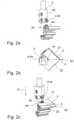
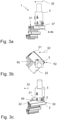
- Figure 1b (this also applies analogously to the figures 2b and 3b ) does not exactly show the perspective of a top view, rather it is a three-dimensional view in which the viewing angle is about 10-20° inclined forwards from the vertical.
- Figure 1b It is easy to see how the device 1 according to the invention is positioned on the outer corner 52 of the partial frame 5 shown here. while showing Figure 1b a partial frame 5 (this can also be a section of an overall frame), which is formed by the two plastic profiles 21 and 22 connected to one another at right angles. The two plastic profiles 21 and 22 were each prepared at a miter angle of 45°.
- the abutting edge 2 is defined by where the two plastic profiles 21, 22 meet; in this case, this is also the miter.
- the abutting edge 2 extends not only in the upper side of the profile 51 shown here (see, for example Figure 1a ), but those Impact edge 2 is formed on the entire miter surface on the outer contour of the plastic profiles 21, 22 abutting here, ie on the inner corner 50, the upper side 51 of the profile, the outer corner 52 and the lower side 53 of the profile.
- the device 1, as shown here, consists (among other things) of a holding body 3. Not shown here, but belonging to the device 1, is a drive and a guide for the holding body 3, through which the holding body 3 moves along the abutting edge 2 is movable and guided in at least one, preferably two or three dimensions.
- the holding body 3 carries several pressure bodies 4, 4a, 4b, 4c.
- the holding body 3 shown here is cuboid.
- a guide rod 39 which interacts with the drive and/or the guide, engages at its upper end.
- the pressure body 4, 4a is provided on the left-hand side wall 38 of the holding body 3 and is used on the outer corner 52.
- the pressure body 4a is arranged approximately in the middle of the side wall 38 and projects somewhat opposite this (and only opposite) side wall 38 .
- the holding body 3 (see in particular Figure 1a ) on its underside 37 another pressure body 4.4b.
- the pressure body 4b can be used both in the area of the underside 37 and, if necessary, on the left-hand side wall 38, since it protrudes slightly over the respective sides or side walls.
- the pressure body 4b is provided for processing the abutting edge 2 present on the upper side 51 of the profile.
- the underside 37 connects the left-hand side wall 38 to the right-hand side wall 36.
- a pressure body 4, 4c is also provided, which protrudes slightly beyond the right-hand side wall 36.
- This pressure body 4c is also arranged in the corner in such a way that parts of this pressure body 4c protrude both from the right-hand side wall 36 and from the underside 37 .
- the pressure bodies 4a, 4b and 4c are preferably designed as rotatably mounted rolling pressure bodies. The exact configuration is described in the sequence of figures 4a to 4h.
- the abutting edge 2 provided on the outer corner 52 is to be machined in the sequence of figures 1a, 1b, 1c.
- the holding body 3 is positioned on the partial frame 5 in such a way that the pressure body 4a on the outer corner 52 is present Bumper 2 is positioned.
- Bumper 2 is positioned.
- the holding body 3 is moved starting from the level of the upper side 51 of the profile to the level of the lower side 53 of the profile.
- the sub-frame 5 is arranged lying down, with its upper profile side 51 being oriented upwards and the lower profile side 53 being oriented downwards, as a result of which the vertically downward movement 30 of the holding body 3 results.
- the arrangement is basically chosen so that during the movement 30 of the holding body 3, a sufficiently large force is exerted by the pressure body 4.4a on the abutting edge 2 (here at right angles to the direction of movement 30, parallel to the frame plane of the partial frame 5, here in the figure after left) acts to equalize or dent the profile overhang there.
- the sub-frame 5 is fixed and clamped by a clamping device, not shown. The exact design of this shaping process depends on the design of the pressure body 4 .
- a separate clamping device is preferably provided for each plastic profile, which is equipped to receive the respective plastic profile and to hold it reliably for the connection process.
- the clamping device is preferably movable in the longitudinal direction of the plastic profile, for which purpose a guide for the clamping elements of the clamping device is provided on the one hand and a corresponding drive on the other.
- the heating provided as an option, which is intended to heat the profile material of the plastic profiles 21, 22 on both sides of the abutting edge 2 and thus to plasticize it in order to facilitate pressing.
- the arrangement is selected such that during the movement 31 of the holding body 3, a sufficiently large force is exerted by the pressure body 4c' on the abutting edge 2 (here at right angles to the direction of movement 31, or parallel to the frame plane of the partial frame 5, here in the figure to the right) acts to equalize or indent the existing profile overhang at the inner corner 50.
- the sub-frame 5 is fixed and clamped by a clamping device, not shown.
- the precise design of this shaping treatment also depends on the design of the pressure body 4c'.
- the processing of the abutting edge 2 on the upper side 51 of the profile is shown.
- the holding body 3 is moved starting from the outer corner 52 in a horizontal movement 32 to the inner corner 50 along the abutting edge 2, here the miter.
- the pressure body 4, 4b protruding on the underside 37 presses with sufficient force onto the top side 51 of the profile. This force is again oriented at right angles to the abutting edge 2 on the top side 51 of the profile and is directed vertically downwards here.
- the rolling pressure body 40 is designed as a simple cylinder.
- the rolling pressure body 40 is equipped with a crowned, outwardly curved lateral surface which, when used on the abutting edge 2, leads to a slight groove.
- the rolling pressure body 40 is formed from three different geometric bodies. Closing flank bodies 42 are provided on each side. These concluding flank bodies 42 are implemented as disks or cylinders. They support the rolling pressure body 40 on the profile surface and level it. A middle region 41 is provided between the two flank bodies 42, which is formed from two truncated cones placed against one another and, when in use, incorporates a V-shaped groove on the abutting edge.
- the rolling pressure body 40 is formed from three different geometric bodies.
- a central body 41 is provided between two disk-shaped flank bodies 42, which has a concave, inwardly curved lateral surface and, when in use, results in a structure that is raised on the profile.
- the rolling pressure body 40 is formed from three different geometric bodies.
- a cylindrical central body 41 is provided between two disc-shaped flank bodies 42; its diameter is greater than the diameter of the temporal flank body 42.
- a U-shaped groove is machined into the abutting edge with this.
- the embodiment after Figure 4h looks like the middle part 41 at first glance Figure 4c , only with steeper angles.
- the design is optimized here, since the respective lateral, outer areas of this rolling pressure body 40 enclose an angle of 80° with one another, whereas the middle areas, in the area of the tip R, enclose an angle of 85°.
- Such a rolling pressure body 40 is preferably used, for example, when processing the abutting edge on an inside corner, with processing angles at the tip R that are smaller than 90° also occurring here, depending on the design of the profile.
- the pressure body is designed as a rolling pressure body, the rolling pressure body itself is formed from 2 cones placed against one another and the tip R that forms in the view preferably has an angle of less than 90°, preferably less than 89°, 88° °, 87° or 85°.
- the advantage of the rotatably mounted rolling pressure body 40 is that it introduces the force into the profile at certain points, i.e. it does not exert any force components in the transverse direction (parallel to the frame plane or direction of the abutting edge 2) on the profile surface.
- this is accompanied by the disadvantage that the use of a roller pressure body 40 should preferably be carried out on large-area abutting edges 2 that are not limited by paragraphs, since the necessary radius of the rolling pressure body 40 abuts such paragraphs and thus limits the effectiveness and usability.
- a sliding pressure body 49 is also proposed, which is applied precisely to the profile or the abutting edge 2 and is thus also positioned at paragraphs of the profile, but is then moved over the profile in a sliding movement.
- the design of such a sliding pressure body 49 as a pressure body 4 is in figure 5 or.
- a further exemplary embodiment of the device 1 is therefore shown.
- the holding body 3 which is shown in more detail here and is formed in several parts, for example, a receptacle 35 is provided in the lower area, which accommodates the pressure body 4 .
- the pressure body 4 is implemented as a sliding pressure body 49, that is to say it is not rotatably mounted.
- the pressure body 4 on the other hand, has a plurality of sliding surfaces 48a and 48b. These sliding surfaces 48a and 48b are angled, e.g figure 5 only the plastic profile 21 is shown, the second plastic profile has been omitted to increase clarity.
- the angle that the two sliding surfaces 48a and 48b enclose with one another is adapted to the resulting angle of the abutting profile areas at the abutting edge.
- sliding surfaces 48a and 48b oriented at an angle to one another, which are usually used simultaneously for processing the abutting edge 2.
- the sliding pressure element 49 it is also possible for the sliding pressure element 49 to have two sliding surfaces 48' and 48" arranged at an angle to one another, which process different areas of the abutting edge in different directions of movement.
- the sliding surface 48" is designed for processing the horizontal profile area
- the Sliding surface 48' is provided for the rising profile area.
- the direction of movement for the use of the different sliding surfaces is different.
- the invention naturally also includes the integrated, one-piece design of a holding body 3 with a pressure body 4 .
Landscapes
- Engineering & Computer Science (AREA)
- Mechanical Engineering (AREA)
- Civil Engineering (AREA)
- Structural Engineering (AREA)
- Physics & Mathematics (AREA)
- Thermal Sciences (AREA)
- Lining Or Joining Of Plastics Or The Like (AREA)
Description
- Die Erfindung betrifft ein Verfahren für das Verbinden zweier Kunststoffprofile, insbesondere zur Herstellung eines Flügel- oder Stockrahmens. Des Weiteren ist eine Vorrichtung für die Bearbeitung zumindest eines Teils der Stoßkante offenbart, die sich beim Verbinden zweier Kunststoffprofile, insbesondere Flügel- oder Stockrahmenprofile ergibt.
- Als Flügelrahmen wird der bewegliche Rahmen bei einem Fenster oder einer Türe angesehen. Der Stockrahmen ist mit dem Gebäude fest verbunden und nimmt den Flügelrahmen auf. Flügel- oder Stockrahmen werden als Tür- oder Fensterrahmen bzw. Rahmen im Zusammenhang mit dieser Beschreibung verstanden.
- Im Stand der Technik ist es bekannt für die Herstellung eines Tür- oder Fensterrahmens bzw. deren Teilrahmen die einzelnen, auf Maß geschnittenen Kunststoffprofilstücke (nachfolgend auch als Kunststoffprofile beschrieben) miteinander zu verschweißen. Üblicherweise wird dem Maß ein möglichst geringes Übermaß aufgeschlagen, das bei dem Verschweißen aufgezehrt wird und für einen festen Verbund der beiden Kunststoffprofile sorgt. Beim Verschweißen werden die zu verbindenden Flächen der Kunststoffprofile, (üblicherweise die auf Gehrung geschnittenen Endbereiche der Kunststoffprofile) zunächst erwärmt (bis diese plastisch werden) und dann in einen Fügeschritt, derart aufeinander zu bewegt, dass die plastifizierten Profilbereiche der zu verbindenden Flächen einander durchdringen und so eine verschweißte Verbindung ergeben.
- Nun kann es sich ergeben, dass sich an der Stoßkante, wo die beiden zu verbindenden Kunststoffprofile aneinander stoßen, sich unschöne Erhebungen oder Schweißwulste bilden. Gründe für diese unschöne Ausgestaltung sind zum Beispiel Maßtoleranzen der zu verarbeitenden Kunststoffprofile oder auch ein ungeschickt geführter Verbindungsprozess. Zum Beispiel wurde das Kunststoffprofil mit einem zu großen Übermaß abgeschnitten und dieser Überstand muss dann beim Verschweißen kompensiert (abgeschmolzen) werden, was dazu führt, dass sich in dem Fügeschritt das zu verdrängende, plastifizierte Kunststoffmaterial in einem sichtbaren Schweißwulst außen, außerhalb der verschweißten Profilstücke sammelt.
- Im Stand der Technik war es bislang bekannt, diesen sich bildenden Schweißwulst zu entfernen, zum Beispiel abzustechen. Allerdings führt dies zu einer am Stoßbereich (zum Beispiel der Gehrung) sichtbaren Hohlkehle, was nicht gewünscht ist.
- Aus
DE 1454937 A1 ist ein Verfahren für das Verbinden zweier Flächengebilde bekannt. Es umfasst das Zusammenführen der beiden Flächengebilde mittels Erwärmen der Flächengebilde durch ein profiliertes Schweißschwert derart, dass sich spätestens mit dem Kontakt der zu verbindenden Flächen der Flächengebilde eine mechanisch stabile Verbindung und zwischen den Flächengebilden eine Stoßkante ergibt, Bewegen einer Glätteinrichtung, die als Druckkörper dient, entlang der Längserstreckung der Stoßkante, wobei die Glätteinrichtung eine Kraft, die spitzwinklig zur Längserstreckung der Stoßkante gerichtet ist, auf die Stoßkante ausübt. -
DE 2348607 A1 offenbart mehrere Verfahren für das Verbinden zweier Kunststoffwände, bzw. eines Akkumulatorbehälters und seines Deckels. Hierzu ist vorgesehen: Zusammenführen des Akkumulatorbehälters und seines Deckels, derart, dass sich spätestens mit dem Kontakt der zu verbindenden Flächen der beiden Elemente eine mechanisch stabile Verbindung und zwischen den beiden Elementen eine Stoßkante ergibt, Bewegen eines als Druckkörper fungierenden Teils quer zu der Längserstreckung der Stoßkante, wobei der das Teil 49 eine Kraft, die spitzbis rechtwinklig zur Längserstreckung der Stoßkante gerichtet ist, auf die Stoßkante ausübt. - Die Erfindung hat es sich daher zur Aufgabe gemacht, diesen Stand der Technik zu verbessern.
- Zur Lösung dieser Aufgabe geht die Erfindung von einem Verfahren wie eingangs beschrieben aus und schlägt die Abfolge folgender Schritte vor:
- ▪ Zusammenführen der beiden Kunststoffprofile, derart dass sich spätestens mit dem Kontakt der zu verbindenden Flächen der Kunststoffprofile eine mechanisch stabile Verbindung und zwischen den Kunststoffprofilen eine Stoßkante ergibt,
- ▪ Bewegen eines Druckkörpers entlang der Längserstreckung der Stoßkante, wobei der Druckkörper eine Kraft, die spitz- bis rechtwinklig zur Längserstreckung der Stoßkante gerichtet ist, auf die Stoßkante ausübt. Der Druckkörper ist als drehbar gelagerter Rolldruckkörper ausgebildet, wodurch es sich bei der Bewegung um ein Abrollen handelt, und
- ▪ Eindrücken einer an der Stoßkante über die Außenkontur der verbundenen Kunststoffprofile hervorstehenden Schweißwulst durch den Druckkörper in den Stoßbereich der beiden Kunststoffprofile.
- Die erfindungsgemäße Lösung ist bei der Art und Weise wie die Kunststoffprofile miteinander verbunden werden sehr flexibel einsetzbar, Beispiele werden weiter unten noch gegeben. Der Pfiff der Erfindung liegt darin, dass gefunden wurde, dass die sich an der Stoßkante ergebende Stufe, Erhebung oder auch der beim Verschweißen entstehende Schweißwulst (nachfolgend umfassend auch als Profilüberstand bezeichnet) durch einen Druckkörper in den Stoßbereich, also dem Bereich wo die beiden Kunststoffprofile aneinander stoßen, hineingedrückt wird.
- Als Stoßkante im Sinne dieser Beschreibung (wobei die nachfolgende Definition nicht abschließend ist) wird der Bereich an einem Rahmen bzw. Teilrahmen verstanden, wo zwei Kunststoffprofile aneinanderstoßen, d.h., die Oberfläche des Rahmens geht von dem ersten auf den zweiten Profilstab über. Üblicherweise ist die Stoßkante linienartig zu verstehen, und gibt insbesondere eine Raumorientierung vor. Hierauf ist der Begriff Stoßkante aber nicht reduziert zu verstehen, da sich an der Stoßkante auch ein Schweißwulst ergeben kann, der eine gewisse Breite aufweist, auch solche eine Ausgestaltung ist von dem Begriff Stoßkante umfasst. Dabei sind die beiden Kunststoffprofile auch an ihrer Oberfläche miteinander verbunden, sie können aber auch hier einen unverbundenen Bereich oder auch einen kleinen Spalt bilden. Auch diese Varianten sind unter dem Begriff Stoßkante zu subsumieren. Zu beachten ist ferner, dass sich die Stoßkante nicht nur an den Sichtoberflächen (der Profilober- bzw. Profilunterseite) ergibt, sondern an allen Profilbereichen, die miteinander verbunden werden, also auch an den mit Absätzen usw. ausgestatteten Innen- bzw. Außenecke.
- Die Stoßkante ist dabei dadurch definiert, wo die beiden Kunststoffprofile aneinander stoßen, dies ist in diesem Fall auch gleichzeitig die Gehrung, die einander zugewandten Querschnittsflächen der Kunststoffprofile werden an den so definierten Gehrungsfläche miteinander verbunden. Dabei erstreckt sich die Stoßkante nicht nur an der Profiloberseite, sondern die Stoßkante bildet sich an der gesamten Gehrungsfläche an der Außenkontur der hier aneinanderstoßenden Kunststoffprofile, also an der Innenecke, der Profiloberseite, der Außenecke und der Profilunterseite, aus. Dabei ist es kein Widerspruch, dass die Stoßkante im Sinne dieser Definition abschnittsweise im Raum anders orientiert ist. Der Begriff "Stoßkante" beschreibt insofern die Gesamtheit des außen, an den Profilen liegenden Begrenzungsbereiches, wie auch einen Teil davon, zum Beispiel an der Profiloberseite, der Außenecke, der Profilunterseite oder der Innenecke, wie auch einen Abschnitt dieses Teiles, was dem Fachmann insofern klar ist.
- Bevorzugt erfolgt die Durchführung des Verfahrens genau in der beschriebenen Reihenfolge (zuerst 1., dann 2.) also
- 1. Zusammenführen der beiden Kunststoffprofile, derart, dass sich spätestens mit dem Kontakt der zu verbindenden Flächen der Kunststoffprofile eine mechanisch stabile Verbindung und zwischen den Kunststoffprofilen eine Stoßkante ergibt,
- 2. Bewegen eines Druckkörpers entlang der Längserstreckung der Stoßkante, wobei der Druckkörper eine Kraft, die spitz- bis rechtwinklig zur Längserstreckung der Stoßkante gerichtet ist, auf die Stoßkante ausübt.
- Überraschenderweise wurde gefunden, dass für das Eindrücken des Profilmaterials dieses nicht erwärmt werden muss. Der erfindungsgemäße Erfolg stellt sich auch bei einem nicht erwärmten Kunststoffprofil bzw. Stoßbereich ein.
- Geschickter Weise ist vorgesehen, dass bevor, insbesondere kurz bevor der Druckkörper entlang der Stoßkante bewegt wird, eine Heizung zumindest den Bereich der Stoßkante erwärmt. Das für die Herstellung von Fensterrahmen eingesetzte Kunststoffmaterial (üblicherweise PVC) ist thermoplastisch, daher unterstützt eine Erwärmung der Stoßkante bzw. des Kunststoffmaterials im Bereich der Stoßkante das Eindrücken dieses Material in das Volumen des Kunststoffprofiles.
- Des Weiteren ist in dem Vorschlag vorteilhafter Weise vorgesehen, dass das Verbinden durch ein Verschweißen der jeweiligen Flächen, zum Beispiel den Gehrungsflächen, erfolgt, wozu diese zumindest teilweise erwärmt und dann aufeinander zu bewegt werden. Beim Verschweißen wird zum Beispiel über einen Heizspiegel oder eine Infrarotheizung erhebliche thermische Energie in die zu verschweißen Kunststoffflächen eingeprägt bis diese plastisch werden. Danach werden die beiden erwärmten Flächen aufeinander zu bewegt (dabei selbstverständlich genau geführt), bis sich diese Flächen einander berühren und die Materialien der beiden Profile einander durchdringen. Wie eingangs beschrieben besteht bei diesem Verfahrensschritt die Möglichkeit, dass sich ein Schweißwulst an der Stoßkante bildet, der zu entfernen ist. Auch wenn heutzutage Verschweißprozesse bekannt sind, bei welchen die zu verschweißenden Gehrungsflächen mit geringstem Übermaß hochgenau vorbereitet werden (zum Beispiel durch einem spanabhebenden Bearbeitungsschritt vor dem Verschweißen), so bestehen doch Maßtoleranzen bei den Kunststoffprofilen, die an der Stoßkante gleichwohl zu einem nicht gewünschten Profilüberstand, Absatz oder Erhebung führt der zumindest optisch bzw. haptisch durch den erfindungsgemäß vorgeschlagenen Verfahrensschritt, unter Einsatz des Druckkörpers beseitigbar ist.
- Des Weiteren ist günstiger Weise vorgesehen, dass die Bewegung des Druckkörpers gleich im Anschluss auf das Verschweißen erfolgt, wenn die Stoßkante noch vom Verschweißen erwärmt ist. Durch diesen Vorschlag wird die im Stoßbereich bzw. an der Stoßkante vorhandene Restwärme des Kunststoffmateriales ausgenutzt und so durch das Eindrücken eine plastische Verformung erreicht. Neben diesem energiesparenden Schritt hat dieser Schritt aber auch den Vorteil, dass Bearbeitungszeit gespart wird, da üblicherweise nach dem Verschweißen zunächst eine gewisse Zeit abgewartet werden muss, bis die Eckverbindung abgekühlt und ausreichend stabil ausgehärtet ist. Während dieser Wartezeit kann dieser Verfahrensschritt ausgeführt werden, er verlängert daher nicht die Produktionszeit, verbessert aber erheblich die optische Gestaltung der Verbindung ohne ihre mechanische Stabilität zu beeinträchtigen.
- Bei einer nicht beanspruchten Ausgestaltung des Vorschlags ist vorgesehen, dass das Verbinden durch ein Verkleben der jeweiligen Flächen, zum Beispiel den Gehrungsflächen, erfolgt, wozu zumindest eine der zu verbindenden Flächen zumindest teilweise mit Klebstoff ausgestattet wird und die Flächen dann aufeinander zu bewegt werden. Natürlich erfolgt auch diese Bewegung möglichst exakt geführt, da hieraus letztendlich die Ausrichtung der Profilstäbe zueinander resultiert und so letztendlich auch die Gestaltung des Rahmens bestimmt wird.
- Wird für das Verbinden ein Verkleben vorgesehen, so kommt man bei der Vorbereitung der Kunststoffprofile ohne Übermaß aus, da die Klebeschicht bereits mit geringer Dicke eine sehr hohe Klebekraft und somit Eckfestigkeit herstellt. Geschickter Weise wird dabei die zu verbindenden Flächen vor dem Verkleben hochgenau (bezüglich des exakten Maßes und auch bezüglich der Parallelität der zu verklebenden Flächen) spanabhebend bearbeitet.
- Der Vorschlag sieht mehrere Varianten vor, wie die zu verbindende Fläche mit Klebstoff ausgestattet wird. Hierzu sind mehrere unterschiedliche Techniken bekannt. So kann die Fläche mit dem Klebstoff bespritzt, besprüht oder benetzt werden. Zum Beispiel wird der Klebstoff (vorzugsweise, aber nicht beschränkend, ein Zweikomponentenkleber, es funktionieren aber auch einfachere Klebstoffe) in einem Sprühkopf unter Druck vorgehalten, der dann den Klebstoff auf die Oberfläche abgibt. Daneben ist es aber auch möglich, den Klebstoff zum Beispiel mit einer Rolle oder mit einem anderen Auftragelement auf die Fläche aufzutragen.
- Gemäß des Vorschlages reicht es bereits aus, wenn eine der zu verbindenden Flächen mit Klebstoff ausgestattet wird, dies schließt natürlich nicht aus, dass beide zu verbindenden Flächen mit Klebstoff vorbereitet werden, wobei zur Offenbarung auch der Vorschlag zählt, auf jede der beiden Flächen je eine Komponente eines Zweikomponentenklebers aufzutragen.
- Die Erfindung umfasste aber noch weitere Verbindungstechniken:
So ist zum Beispiel vorgesehen, dass eine Verbindung auch über ein in die beiden Kunststoffprofile eingestecktes Verbindungs- oder Adapterstück erfolgen kann. - Des Weiteren ist es auch möglich, dass eine Verbindung über ein Heißkleben erfolgt.
- Natürlich können auch die vorgenannten Varianten miteinander kombiniert werden, die Liste der Aufzählungen ist nicht abschließend.
- In einer vorteilhaften Ausgestaltung ist vorgesehen, dass ein an der Stoßkante über die Außenkontur der verbundenen Kunststoffprofile hervorstehender Schweißwulst oder sich im Bereich der Stoßkante nach dem Verbinden ergebende Erhebung, Überstand oder Höhenunterschied durch den Druckkörper in den Stoßbereich der beiden Kunststoffprofile eingedrückt wird. Als Profilüberstand wird jede Art von Schweißwulst, Erhebung, Überstand, Absatz oder Höhenunterschied verstanden.
- Es ist ein Vorzug des Vorschlages, dass die sich beim Verbinden der Profile eventuell ergebenden, an der Stoßkante befindlichen unschönen Profilüberstände, Versätze, Erhebungen oder Überstände aber auch Schweißwulste durch den Vorschlag, ohne spanabhebend tätig zu werden, beseitigen lassen.
- Beachtenswert ist dabei insbesondere, dass das sehr gute Bearbeitungsergebnis hierbei ohne eine weitere, zusätzliche vorhergehende spanabhebende Bearbeitung an der Begrenzungskante des Profiles (also zum Beispiel an der Profiloberseite) erreicht wird. Der erfindungsgemäße Vorschlag kommt vollständig ohne die Anordnung einer Phase oder Nut an der Profilaußenseite aus. Da kein zusätzlicher Bearbeitungsschritt notwendig ist, ist der Vorschlag für den Anwender auch effektiv, da Bearbeitungszeit gespart und gleichzeitig ein sehr gutes Bearbeitungsergebnis erreicht wird.
- Vereinfacht gesagt werden mit dem erfindungsgemäßen Vorschlag die Ungenauigkeiten an der Stoßkante in die Kunststoffprofile eingebügelt. Dabei ist es günstig, dass die Kunststoffprofile nicht aus Vollmaterial bestehen, sondern Hohlkammern aufweisen, die ein Raumreservoir für die Aufnahme des in das Kunststoffprofilinnere eingedrückte, überflüssige Material bildet.
- Ein Vorzug der Erfindung liegt darin, dass das Eindrücken des Profilüberstandes zeitlich nicht festgelegt ist. So kann dieses Eindrücken gleich nach dem Verbinden der beiden Kunststoffprofile erfolgen, wenn diese beiden noch aufgrund des Verbindungsprozesses in einer gemeinsamen Aufspannung zueinander fixiert sind.
- Es ist aber auch möglich, das Eindrücken in einer separaten Station, die von der Station des Verbindens funktional getrennt ist, durchzuführen. In einem solchen Fall wird zum Beispiel eine Bearbeitung nur durchgeführt, wenn bei einer Begutachtung der Stoßkante die Qualität derselben noch nicht ausreichend ist. Dabei erfolgt eine solche Überprüfung in einer Qualitätsstation. Diese kann diese Überprüfung zum Beispiel mechanische und/oder optische Kriterien zu Grunde legen. So folgt nach der Verbindungsstation eine Qualitätsstation und hernach die Station zur Bearbeitung der Stoßkante. Die beiden vorgenannten Ausführungsvarianten gehören zur Erfindung.
- Des Weiteren wird eine Vorrichtung offenbart, die für die Bearbeitung zumindest eines Teils der Stoßkante vorgesehen ist, die sich beim Verbinden zweier Kunststoffprofile, insbesondere zur Herstellung eines Flügel- oder Stockrahmens ergibt.
- Eine solche Vorrichtung weist einen Haltekörper auf, der mindestens einen Druckkörper trägt, wobei der Druckkörper dafür vorgesehen ist, durch den Haltekörper entlang der Längserstreckung der Stoßkante bewegt zu werden, wobei der Druckkörper eine Kraft, die spitz- bis rechtwinklig zur Längserstreckung der Stoßkante gerichtet ist, auf die Stoßkante ausübt und der Haltekörper zumindest entlang einer Raumachse durch einen Antrieb bewegbar und durch eine Führung geführt ist.
- Erfindungsgemäß ist zudem vorgesehen, dass der Druckkörper als drehbar gelagerter Rolldruckkörper ausgebildet ist. Mit einem solchen als Rolldruckkörper ausgebildeten Druckkörper erfolgt das Eindrücken des Profilüberstandes als ein Einrollen. Der Vorzug dieser Variante liegt darin, dass die Kunststoffprofile idealerweise nur punktuell und auch nur in eine Richtung rechtwinklig zur Rahmenebene mit Kraft beaufschlagt werden. Ein solcher Vorschlag ist insbesondere bei folienbeschichteten Kunststoffprofilen günstig, bei welchen eine transversale Kraft (mit Bewegungsanteilen in Längsrichtung der Stoßkante) unter Umständen zu einer Beschädigung dieser Beschichtungsfolie führen könnte.
- Der Einsatz dieser Vorrichtung kann in der gleichen Maschine erfolgen in welcher auch das Verbinden der Kunststoffprofile durchgeführt wird. Die vorgeschlagene Vorrichtung kann aber auch Gegenstand einer von dieser Maschine getrennten Bearbeitungsstation sein. In der Regel werden die Kunststoffprofile jeweils in einer Spannvorrichtung aufgespannt und sind daher stabil gelagert. Die Vorrichtung umfasst oder wirkt daher mit je einer entsprechenden Spannvorrichtung für das jeweilige Kunststoffprofil zusammen.
- Vorzugsweise ist dabei für jedes Kunststoffprofil eine eigene Spannvorrichtung vorgesehen, die dafür ausgestattet ist, das jeweilige Kunststoffprofil aufzunehmen und für den Verbindungsvorgang zuverlässig zu halten. Dabei ist die Spannvorrichtung vorzugsweise in Längsrichtung des Kunststoffprofiles beweglich, wofür einerseits eine Führung für die Spannelemente der Spannvorrichtung und andererseits ein entsprechender Antrieb vorgesehen ist.
- Oftmals befindet sich die Stoßkante im Bereich der Gehrung, also im Eckbereich der miteinander verbundenen Kunststoffprofile. Der Profilüberstand an der Stoßkante erstreckt sich dabei nicht nur auf der Profilober- oder Unterseite, die dem Benutzer unmittelbar sichtbar ist, sie streckt sich auch in den Innen- und Außenbereich, insbesondere der Innenecke bzw. Außenecke des Rahmens und ist auch dort aus funktionalen, aber auch aus ästhetischen Gründen nicht erwünscht.
- Der Anwendungsfall der Erfindung ist aber auf die Eckverbindung, also die auf die Gehrung miteinander verbundenen Kunststoffprofile, nicht beschränkt. Auch eingesetzte Pfosten, sogenannte Kämpfer, können, nachdem diese mit dem Längsprofil verbunden sind, gemäß der Erfindung bearbeitet werden und so eine optisch wir auch haptisch ansprechende Stoßkantenausbildung erfahren.
- Geschickter Weise besitzt die Vorrichtung einen Haltekörper. Der Haltekörper ist vorzugsweise entlang mindestens einer Raumachse, insbesondere vorzugsweise in der Ebene der Gehrungsfläche, die ja auch die Stoßkante beinhaltet, beweglich gelagert. Natürlich liegt die Raumachse, entlang der der Haltekörper beweglich ist, vorzugsweise in der Gehrungsfläche. An der Gehrungsfläche sind die beiden Kunststoffprofile miteinander verbunden, zum Beispiel verschweißt oder verklebt.
- Der Haltekörper trägt zumindest einen Druckkörper. Aufgrund der Beweglichkeit des Haltekörpers ist der Druckkörper entlang der Stoßkante (durch eine Bewegungskraft) bewegbar. Nun ist die Anordnung so gewählt, dass bei einer Bewegung des Druckkörpers über die Stoßkante, also über die verbundenen Kunststoffprofile, eine entsprechende Kraft auf die Stoßkante ausgeübt wird (=Andrückkraft). Die beiden miteinander verbundenen Kunststoffprofile definieren eine Rahmenebene. Vorzugsweise ist die von dem Druckkörper erzeugte Kraft spitz- bis rechtwinklig zu dieser Rahmenebene orientiert bzw. besitzt zumindest einen nicht unerheblichen Kraftanteil rechtwinklig zur Rahmenebene, der ausreicht, diesem Profilüberstand in den Stoßbereich einzudrücken.
- Letztlich schließt die Kraftkomponente, die von den Druckkörpern auf die Kunststoffprofile eingeprägt wird mit der Längserstreckung der Stoßkante in diesem Bereich einen spitzen bis rechtwinkligen Winkel ein, der aus der Überlagerung der Andrückkraft und der Bewegungskraft resultiert.
- Erreicht wird dies durch eine entsprechende konstruktive Ausgestaltung. Der Haltekörper ist zumindest entlang einer Raumachse beweglich gelagert und geführt. Rechtwinklig zur dieser Raumachse, bevorzugt auch rechtwinklig zur Rahmenebene, ist der Haltekörper zum Beispiel gegen die Kraft eines Kraftreservoirs, wie einer Druckfeder oder einem Pneumatikzylinder vorgespannt. Durch diese Vorspannung wird erreicht, dass der Haltekörper bei Einwirken auf die Kunststoffprofile zurückfedern kann und so eine ausreichende Kraftreserve besitzt um auf dem Profilüberstand an der Stoßkante einzuwirken.
- Vergleichbares kann auch dadurch erreicht werden, dass der Druckkörper federbelastet im Halterkörper gelagert ist.
- Die hierbei auftretenden Bearbeitungskräfte werden über den (Teil-) Rahmen bzw. Kunststoffprofile/Profilstäbe auf die Spannvorrichtungen, die die Kunststoffprofile tragen und halten, übertragen.
- Die offenbarungsgemäße Vorrichtung ist konstruktiv einfach wie in seiner Wirkung hocheffizient. Durch ihren Vorschlag wird ein einfaches Mittel zur Verfügung gestellt um ein im Stand der Technik erhebliches Problem zu lösen, nämlich die oftmals unvermeidbaren Profilüberstände optisch aber auch haptisch so zu beeinflussen, dass diese nicht oder kaum mehr wahrnehmbar sind und dabei keine unschönen Bearbeitungsspuren, wie zum Beispiel Hohlkehlen hinterlässt. Dabei ist die offenbarungsgemäße Vorrichtung sowohl an den großflächigen Sichtbereichen an den Stoßbereichen bzw. Gehrungsflächen, wie auch an den filigranen, engen Innen- oder Außenecken einsetzbar.
- In einer weiteren bevorzugten Ausführungsform ist vorgesehen, dass der Druckkörper zumindest teilweise über den Haltekörper vorsteht, derart, dass bei einer Bewegung des Haltekörpers durch den Antrieb entlang einer Raumachse der Druckkörper auf die Stoßkante einwirkt.
- Des Weiteren ist vorgesehen, dass der Druckkörper am Haltekörper bevorzugt an dessen Eckbereich angeordnet ist. Vorzugsweise ist vorgesehen, dass der Haltekörper mehrere Druckkörper trägt. Geschickter Weise ist die Anordnung dabei so gewählt, dass die einzelnen Druckkörper jeweils für die Bearbeitung spezieller Bereiche an der Stoßkante vorgesehen und optimiert sind. So ist zum Beispiel ein erster Druckkörper für die dem Benutzer zugewandte Profiloberseite vorgesehen. Ein zweiter bzw. dritter Druckkörper sind je für das Verarbeiten der Innen- bzw. Außenecke vorgesehen und sind dabei von dem ersten Druckkörper beabstandet und so an dem Haltekörper angeordnet, dass diese unabhängig voneinander einsetzbar sind. Auch die Ausgestaltung der Druckkörper ist für die jeweilige Bearbeitungsaufgabe angepasst, daher sind die Druckkörper nicht zwingend alle gleich ausgestaltet.
- Des Weiteren ist vorgesehen, dass die Vorrichtung, der Haltekörper und/oder der Druckkörper eine Heizung für das Erwärmen zumindest des Bereichs der Stoßkante aufweist. Auch wenn gefunden wurde, dass auch der nicht erwärmte bzw. erkaltete Profilüberstand an der Stoßkante mit dem nach der Erfindung vorgeschlagenen Druckkörper erfolgreich bearbeitet werden kann, so wird durch den Einsatz einer Heizung, die für die Erwärmung zumindest des Bereichs der Stoßkante und somit auch des Profilüberstandes vorgesehen ist, eine Verbesserung des Arbeitsergebnisses erreicht. Es ist klar, dass sich die Stoßkante dabei nicht nur auf den jeweiligen Sichtoberflächen (Profilober- bzw. Unterseite), sondern auch im Innen- bzw. Außeneck des Rahmens erstreckt.
- Dabei ist gefunden worden, dass es möglich ist, an verschiedenen Elementen eine Heizung einzusetzen. In einer ersten Variante ist dabei vorgesehen, dass an der Vorrichtung selber eine Heizung, zum Beispiel ein Heizspiegel oder Ähnliches, getrennt von dem Halte- bzw. Druckkörper vorgesehen ist und zum Beispiel durch eine eigene bewegliche Achse gegen die Stoßkante anstellbar ist. Vorteil dieser Variante ist, dass für diese Erwärmungsaufgabe zum Beispiel bereits an der Vorrichtung vorgesehene Heizelemente, namentlich zum Beispiel der Heizspiegel, der auch für das Verschweißen eingesetzt wird, nochmals genutzt werden kann.
- Bei einer zweiten Variante ist die Heizung an dem Haltekörper angeordnet. Sie befindet sich zum Beispiel als separates Element auf dem Haltekörper und ist von dem Druckkörper getrennt ausgebildet. Vorteil dieser Variante ist, dass die Heizung dann zum Beispiel kurz vor dem Eindrückvorgang eingesetzt werden kann und ein separater Antrieb für die Heizung nicht notwendig ist, da hierfür der Antrieb des Haltekörpers mit genutzt werden kann.
- In einer dritten Variante ist vorgesehen, dass der Druckkörper selber die Heizung aufnimmt bzw. besitzt. Vorteil dieser Variante ist, dass somit die Heizenergie punktuell exakt beim Eindrücken des Profilüberstandes zur Verfügung gestellt wird und aufgrund des begrenzten räumlichen Anwendungsbereiches die Gefahrenquelle eines heißen Maschinenelementes reduziert ist.
- Es ist klar, dass die Offenbarung natürlich auch eine Kombination der verschiedenen Heizkonzepte umfasst.
- Bei einer bevorzugten Ausgestaltung des Vorschlags ist vorgesehen, dass als Heizung ein Heizspiegel, eine Infrarotheizung oder eine Widerstandsheizung vorgesehen ist. Natürlich sind auch noch andere Heizkonzepte, die der Fachmann kennt, von der Findung umfasst.
- Ein weiterer Vorzug des Vorschlages liegt darin, dass die Druckkörper, insbesondere die Rolldruckkörper an dem Haltekörper austauschbar angeordnet sind. So ist es zum Beispiel einfach möglich Rolldruckkörper auszutauschen und so auch deren Bearbeitungsprofil zu verändern. Wie insbesondere noch bei der Zeichnung beschrieben wird, besitzen die Rolldruckkörper im Schnitt gesehen sehr variable Ausgestaltungsvarianten, die es dann erlauben, zusätzlich an der Stoßkante nicht nur den Profilüberstand zu bearbeiten, sondern gegebenenfalls auch gleichzeitig eine vom Benutzer gewünschte Prägung oder optische Gestaltung an der Gehrung des Rahmens einzuarbeiten. In einer bevorzugten Ausgestaltung wird daher vorgeschlagen, dass der Rolldruckkörper, im Querschnitt gesehen, konvexe oder konkave Bereiche aufweist.
- In einer nicht vom Anspruchswortlaut umfassten Ausgestaltung ist vorgesehen, dass der Druckkörper als Gleitdruckkörper, insbesondere mit einer reibarmen Gleitoberfläche ausgebildet ist. Im Einsatzfall wird der Gleitdruckkörper über die Stoßkante bzw. den Profilbereich gezogen. Bei dieser Variante ist der Druckkörper als an dem Haltekörper einsetzbares, insbesondere auf die spezielle Bearbeitungsaufgabe optimiertes, starres Werkzeug ausgebildet. Um mögliche Beeinträchtigungen des Kunststoffprofiles zu minimieren, ist die Gleitoberfläche, die auf die Kunststoffprofile, insbesondere den Profilüberstand, wirkt, mit einer Reibung reduzierenden Beschichtung ausgestattet, hierzu kann zum Beispiel Teflon dienen. Ein solcher Druckkörper ist insbesondere bei unbeschichteten Kunststoffprofilen und/oder auch für filigrane Eckbearbeitungen von Vorteil.
- Unter Umständen kann es nämlich ausreichend sein, bei filigranen Anwendungen, wie zum Beispiel in der Innen- oder Außenecke den Gleitdruckkörper gegen die Stoßkante rechtwinklig anzustellen, diesen flächig aufzudrücken, so die Eindrückkraft auf die Stoßkante auszuüben und so den Profilüberstand einzudrücken. In diesem Fall ist eine Bewegung des Druckkörpers in Richtung der Stoßkante nicht zwingend erforderlich. Gegebenenfalls ist dabei die Größe des Druckkörpers dem jeweiligen Profil und Anwendungsfall angepasst.
- Beachtenswert ist dabei insbesondere, dass das sehr gute Bearbeitungsergebnis hierbei ohne eine weitere, zusätzliche vorhergehende spanabhebende Bearbeitung an der Begrenzungskante des Profiles (also zum Beispiel an der Profiloberseite) erreicht wird. Der erfindungsgemäße Vorschlag kommt vollständig ohne die Anordnung einer Phase oder Nut an der Profilaußenseite aus. Da kein zusätzlicher Bearbeitungsschritt notwendig ist, ist der Vorschlag für den Anwender auch effektiv, da Bearbeitungszeit gespart und gleichzeitig ein sehr gutes Bearbeitungsergebnis erreicht wird.
- In einer weiteren nicht vom Anspruchswortlaut umfassten Ausführungsform ist vorgesehen, dass der Gleitdruckkörper mindestens zwei winklig zueinander orientierte Gleitoberflächen aufweist.
- Unter diese bevorzugte Ausführungsform lassen sich mehrere Gestaltungsvarianten subsumieren. Bei der ersten Variante wird mit einer ersten Gleitoberfläche ein erster Bereich der Stoßkante bearbeitet. Mit der zweiten Gleitoberfläche wird ein zweiter, von dem ersten Bereich beabstandeter Bereich der Stoßkante bearbeitet.
- Bei der zweiten Variante dieses Vorschlages wirken beide, winkelig zueinander angestellten Gleitoberfläche auf beidseitig, an der Stoßkante (zum Beispiel links und rechts der Stoßkante) anschließenden Kunststoffprofilbereiche ein. Dieser Anwendungsfall ist zum Beispiel bei der Bearbeitung der Außen- oder Innenecke gegeben.
- Bei einer dritten Variante werden die beiden vorbeschriebenen Gestaltungsvarianten miteinander kombiniert.
- Die Mehrzahl von Gleitoberflächen dient dazu unterschiedliche Bereiche der Stoßkante am Rahmen bzw. Teilrahmen mit ein und denselben Gleitdruckkörper zu bearbeiten. Ein solcher Vorschlag ist platzsparend, da insbesondere bei den Eckbearbeitungen große Gleitdruckkörper hinderlich sein können und mit kleinen, komplex aufgebauten Gleitdruckkörper viele Bereiche der Stoßkante erreicht werden können. Üblicherweise ist der Haltekörper in eine Richtung parallel zur Ausrichtung der Gleitoberfläche beweglich angeordnet. Dadurch wird erreicht, dass der Gleitdruckkörper in gewünschter Weise über die Stoßkante der Kunststoffprofile bewegt wird. Besitzt nun ein solcher Gleitdruckkörper mehrere, winklig zueinander angeordnete Gleitoberflächen (die für eine Bearbeitung unterschiedlicher Bereiche der Stoßkante vorgesehen sind), so ist natürlich auch die Beweglichkeit des Haltekörpers hierauf angepasst. Er ist dann vorzugsweise in einer Ebene parallel zur Gehrungsfläche bewegbar ausgeführt.
- Vorteilhafter Weise umfasst die Erfindung mehrere unterschiedliche Varianten von Druckkörpern.
- Die verschiedenen Varianten von Druckkörpern haben, wie vorbeschrieben, unterschiedliche Vorzüge und Eigenschaften. Geschickter Weise ist der Haltekörper so universell ausgestaltet, dass er sowohl für die Aufnahme eines als Druckrollenkörpers ausgebildeten Druckkörpers, wie auch eines als Gleitdruckkörpers ausgebildeten Druckkörpers dient. An dem Haltekörper sind entsprechend universell ausgestaltete Aufnahmen vorgesehen, die auch einen schnellen Austausch der unterschiedlichen Druckkörpervarianten erlaubt, um so zum Beispiel während der Produktion kurzfristig auf einen anderen Profiltyp umrüsten zu können.
- Des Weiteren umfasst die Offenbarung auch die vorteilhafte Verwendung eines Druckkörpers, der als drehbar gelagerter Rolldruckkörper ausgebildet ist und entlang zumindest einer Raumachse geführt und beweglich gelagert ist, zum Eindrücken einer Schweißwulst, Erhebung, eines Überstandes oder Höhenunterschiedes an der Stoßkante, die sich beim Verbinden zweier Kunststoffprofile, insbesondere bei der Herstellung eines Tür- oder Fensterrahmens oder - Teilfensterrahmens ergibt, in den Stoßbereich.
- Beachtenswert ist dabei insbesondere, dass das sehr gute Bearbeitungsergebnis hierbei ohne eine weitere, zusätzliche vorhergehende spanabhebende Bearbeitung an der Begrenzungskante des Profiles (also zum Beispiel an der Profiloberseite) erreicht wird. Der erfindungsgemäße Vorschlag kommt vollständig ohne die Anordnung einer Phase oder Nut an der Profilaußenseite aus. Da kein zusätzlicher Bearbeitungsschritt notwendig ist, ist der Vorschlag für den Anwender auch effektiv, da Bearbeitungszeit gespart und gleichzeitig ein sehr gutes Bearbeitungsergebnis erreicht wird.
- Als Stoßbereich sei hierbei der Bereich der beiden miteinander verbundenen Kunststoffprofile verstanden, die sich an der Stoßkante anschließen, bzw. durch ihr Zusammenwirken die Stoßkante definieren. Der Stoßbereich ist dabei insbesondere auch das Material der Kunststoffprofile, in welche das über- oder vorstehende Profilmaterial (der Profilüberstand) eingewalzt oder eingerollt wird.
- Insbesondere treten auch bei der zur Erfindung gehörenden Verwendung all die Vorteile, die im Zusammenhang mit dem Verfahren bzw. der Vorrichtung gemäß der Erfindung beschrieben sind, in gleicher Weise zutage.
- Zusammengefasst ergeben die verschiedenen vorbeschriebenen Ausführungsvarianten des Vorschlages einen reichen Schatz von Vorteilen.
- Das Eindrücken bewirkt, unabhängig von dem Verbindungsverfahren (Verschweißen oder Verkleben) der Kunststoffprofile eine optimale Ausbildung der Stoßkante, insbesondere auf der Profiloberfläche, die dem Betrachter zugewandt ist.
- Der Vorschlag umfasst aber auch Lösungen, wie die Eckbereiche (innen wie außen) des Fensterrahmens in gleicher Qualität bearbeitet werden können.
- Überraschenderweise ist eine solche Bearbeitung auch mit nicht erwärmten Profil erfolgreich durchführbar.
- Der gemäß der Erfindung vorgeschlagene Ablauf kann auch als Finishen durch Rollen (zum Beispiel mit einem abrollenden Rolldruckkörper) oder Finishen durch Abdrücken (zum Beispiel mit einem gezogenen Druckkörper) bezeichnet werden.
- In diesem Zusammenhang wird insbesondere darauf hingewiesen, dass alle in Bezug auf die Vorrichtung beschriebenen Merkmale und Eigenschaften aber auch Verfahrensweisen sinngemäß auch bezüglich der Formulierung des erfindungsgemäßen Verfahrens übertragbar und im Sinne der Erfindung einsetzbar und als mitoffenbart gelten. Gleiches gilt auch in umgekehrter Richtung, das bedeutet, nur im Bezug auf das Verfahren genannte, bauliche also vorrichtungsgemäße Merkmale können auch im Rahmen der Vorrichtungsansprüche berücksichtigt und beansprucht werden und zählen ebenfalls zur Offenbarung.
- Gleiches gilt auch mit Blick auf die offenbarungsgemäße Verwendung, d.h., alle im Bezug auf das erfindungsgemäße Verfahren oder Vorrichtung beschriebenen Merkmale oder Anwendungsfälle sind in gleicher Weise auf die offenbarungsgemäße Verwendung zu übertragen, gehören zur Offenbarung dieser Anmeldung.
- In der Zeichnung ist die Erfindung insbesondere in mehreren Ausführungsbeispielen schematisch dargestellt. Es zeigen:
- Fig. 1a, 2a, 3a
- je in einer Seitenansicht verschiedene Stellungen des Haltekörpers relativ zu den Kunststoffprofilen gemäß der Erfindung,
- Fig. 1b, 2b, 3b
- je in einer dreidimensionalen Ansicht von oben verschiedene Stellungen des Haltekörpers relativ zu den Kunststoffprofilen gemäß der Erfindung,
- Fig. 1c, 2c, 3c
- je in einer dreidimensionalen Ansicht verschiedene Stellungen des Haltekörpers relativ zu den Kunststoffprofilen gemäß der Erfindung, wobei die Figurensequenz 1a, 1b und 1c sowie die Figurensequenz 2a, 2b, 2c und die Figurensequenz 3a, 3b und 3c jeweils zu einer gemeinsamen Stellung des Haltekörpers relativ zu den Kunststoffprofilen gehören,
- Fig. 4a bis 4h
- je in einer Seitenansicht verschiedene Varianten des Druckkörpers gemäß der Erfindung,
- Fig. 5
- in einer dreidimensionalen Ansicht ein weiteres Ausführungsbeispiel der erfindungsgemäßen Vorrichtung, und
- Fig. 6a, 6b
- je in einer dreidimensionalen Ansicht verschiedene Stellungen des Haltekörpers eines weiteren Ausführungsbeispieles relativ zu den Kunststoffprofilen gemäß der Erfindung,
- In den Figuren sind gleiche oder einander entsprechende Elemente jeweils mit den gleichen Bezugszeichen bezeichnet und werden daher, sofern nicht zweckmäßig, nicht erneut beschrieben. Die in der gesamten Beschreibung enthaltenen Offenbarungen sind sinngemäß auf gleiche Teile mit gleichen Bezugszeichen bzw. gleichen Bauteilbezeichnungen übertragbar. Auch sind die in der Beschreibung gewählten Lageangaben, wie z.B. oben, unten, seitlich usw. auf die unmittelbar beschriebene sowie dargestellte Figur bezogen und sind bei einer Lageänderung sinngemäß auf die neue Lage zu übertragen. Weiterhin können auch Einzelmerkmale oder Merkmalskombinationen aus den gezeigten und beschriebenen unterschiedlichen Ausführungsbeispielen für sich eigenständige, erfinderische oder erfindungsgemäße Lösungen darstellen.
- In
Figur 1b (dies gilt analog auch für dieFiguren 2b und3b ) ist nicht exakt die Perspektive einer Draufsicht gezeigt, vielmehr ist es eine dreidimensionale Ansicht, bei welchen der Betrachtungswinkel ca. 10-20° gegen die Vertikale nach vorne geneigt ist. InFigur 1b ist gut zu erkennen, wie die erfindungsgemäße Vorrichtung 1 an der Außenecke 52 des hier gezeigten Teilrahmens 5 positioniert ist. Dabei zeigtFigur 1b einen Teilrahmen 5 (dies kann auch der Ausschnitt eines Gesamtrahmens sein), das durch die zwei rechtwinklig miteinander verbundenen Kunststoffprofile 21 und 22 gebildet ist. Dabei wurden die beiden Kunststoffprofile 21 und 22 je unter einem Gehrungswinkel von 45° vorbereitet. - Die Stoßkante 2 ist dabei dadurch definiert, wo die beiden Kunststoffprofile 21,22 aneinander stoßen, dies ist in diesem Fall auch gleichzeitig die Gehrung. Dabei erstreckt sich die Stoßkante 2 nicht nur in der hier gezeigten Profiloberseite 51 (siehe zum Beispiel
Figur 1a ), sondern die Stoßkante 2 bildet sich an der gesamten Gehrungsfläche an der Außenkontur der hier aneinanderstoßenden Kunststoffprofile 21,22, also an der Innenecke 50, der Profiloberseite 51, der Außenecke 52 und der Profilunterseite 53, aus. - Die Vorrichtung 1, wie sie hier gezeigt ist, besteht (unter anderem) aus einen Haltekörper 3. Hier nicht gezeigt, aber zur Vorrichtung 1 gehörend, ist ein Antrieb und eine Führung für den Haltekörper 3, durch welchen der Haltekörper 3 entlang der Stoßkante 2 zumindest ein-, bevorzugt zwei- oder dreidimensional bewegbar und geführt ist.
- Der Haltekörper 3 trägt mehrere Druckkörper 4,4a, 4b, 4c. Der hier dargestellte Haltekörper 3 ist quaderförmig gebildet. An seinem oberen Ende greift eine Führungsstange 39 an, die mit dem Antrieb und/oder der Führung zusammenwirkt.
- In der Figurensequenz 1a, 1b und 1c ist an der linken Seitenwand 38 des Haltekörpers 3 der Druckkörper 4,4a vorgesehen, der an der Außenecke 52 in Einsatz ist. Dabei ist der Druckkörper 4a ungefähr in der Mitte der Seitenwand 38 angeordnet und steht etwas gegenüber dieser (und nur gegenüber dieser) Seitenwand 38 vor.
- Des Weiteren trägt der Haltekörper 3 (siehe hierzu insbesondere
Figur 1a ) an seiner Unterseite 37 einen weiteren Druckkörper 4,4b. Genau genommen ist der Druckkörper 4b sowohl im Bereich der Unterseite 37, wie auch gegebenenfalls an der linken Seitenwand 38 einsetzbar, da er über die jeweiligen Seiten bzw. Seitenwände ein wenig vorsteht. Der Druckkörper 4b ist für die Bearbeitung der an der Profiloberseite 51 vorhandenen Stoßkante 2 vorgesehen. - Die Unterseite 37 verbindet dabei die linke Seitenwand 38 mit der rechten Seitenwand 36. Es ist des Weiteren ein Druckkörper 4,4c vorgesehen, der etwas über die rechte Seitenwand 36 vorsteht. Auch diese Druckkörper 4c ist in der Ecke angeordnet derart, dass Teile dieses Druckkörpers 4c sowohl gegenüber der rechten Seitenwand 36, wie auch gegenüber der Unterseite 37 vorstehen.
- Die Druckkörper 4a, 4b und 4c sind vorzugsweise als drehbar gelagerte Rolldruckkörper ausgebildet. Die genaue Ausgestaltung wird in der Figurensequenz 4a bis 4h beschrieben.
- Wie eingangs bereits beschrieben ist in der Figurensequenz 1a, 1b, 1c die an der Außenecke 52 vorgesehene Stoßkante 2 zu bearbeiten. Hierzu wird der Haltekörper 3 derart an dem Teilrahmen 5 positioniert, dass der Druckkörper 4a an der an der Außenecke 52 vorhandenen Stoßkante 2 positioniert ist. Dann erfolgt eine Bewegung des Haltekörpers 3 in vertikaler Richtung nach unten, hier dargestellt durch den Pfeil 30. Genau genommen wird der Haltekörper 3 beginnend von der Ebene der Profiloberseite 51 auf die Ebene der Profilunterseite 53 bewegt. In dem hier gezeigten Ausführungsbeispiel ist der Teilrahmen 5 liegend angeordnet, wobei seine Profiloberseite 51 oben und die Profilunterseite 53 unten orientiert ist, wodurch sich die vertikal nach unten gerichtete Bewegung 30 des Haltekörpers 3 ergibt.
- Dabei ist die Anordnung grundsätzlich so gewählt, dass bei der Bewegung 30 des Haltekörpers 3 eine ausreichend große Kraft von den Druckkörper 4,4 a auf die Stoßkante 2 (hier rechtwinklig zur Bewegungsrichtung 30, parallel zur Rahmenebene des Teilrahmen 5, hier in der Figur nach links) einwirkt, um dem dort vorhandenen Profilüberstand zu egalisieren oder einzudrücken. Natürlich ist dabei der Teilrahmen 5 durch eine nicht gezeigte Spannvorrichtung festgelegt und aufgespannt. Die genaue Ausgestaltung dieser formgebenden Bearbeitung hängt von der Ausgestaltung des Druckkörpers 4 ab.
- Vorzugsweise ist dabei für jedes Kunststoffprofil eine eigene Spannvorrichtung vorgesehen, die dafür ausgestattet ist, das jeweilige Kunststoffprofil aufzunehmen und für den Verbindungsvorgang zuverlässig zu halten. Dabei ist die Spannvorrichtung vorzugsweise in Längsrichtung des Kunststoffprofiles beweglich, wofür einerseits eine Führung für die Spannelemente der Spannvorrichtung und andererseits ein entsprechender Antrieb vorgesehen ist.
- In den verschiedenen Figurensequenzen nicht dargestellt ist die optional nach einem Vorschlag vorgesehene Heizung, die dafür vorgesehen ist, das Profilmaterial der Kunststoffprofile 21, 22 beidseits der Stoßkante 2 zu erwärmen und so zu plastifizieren, um das Eindrücken zu erleichtern.
- In der Figurensequenz 2a, 2b und 2c ist die Bearbeitung der Stoßkante 2 in der Innenecke 50 gezeigt. Hierzu ist der Haltekörper 3 über der Innenecke 50 positioniert und wird dort in einer vertikalen Bewegung 31 (analog der Bewegung 30) nach unten bewegt derart, dass der an der rechten Seitenwand 36 angeordnete Druckkörper 4c auf die Innenecke 50 einwirkt. Die Innenecke 50 liegt dabei an dem Profil der Außenecke 52 gegenüber.
InFigur 2a und Figur 2c ist mit 4c'die Stellung des in die Innenecke 50 eingetauchten Druckkörper 4c' beispielhaft gezeigt, um zu verdeutlichen, wie der Druckkörper 4c' an der Innenecke 50 anliegt. - Dabei ist auch hier die Anordnung so gewählt, dass bei der Bewegung 31 des Haltekörpers 3 eine ausreichend große Kraft von den Druckkörper 4c' auf die Stoßkante 2 (hier rechtwinklig zur Bewegungsrichtung 31, bzw. parallel zur Rahmenebene des Teilrahmen 5, hier in der Figur nach rechts) einwirkt, um den an der Innenecke 50 vorhandenen Profilüberstand zu egalisieren oder einzudrücken. Natürlich ist dabei der Teilrahmen 5 durch eine nicht gezeigte Spannvorrichtung festgelegt und aufgespannt. Die genaue Ausgestaltung dieser formgebenden Bearbeitung hängt auch hier von der Ausgestaltung des Druckkörpers 4c' ab.
- In der Figurensequenz 3a, 3b und 3c ist die Bearbeitung der Stoßkante 2 auf der Profiloberseite 51 gezeigt. Hierzu wird der Haltekörper 3 beginnend von der Außenecke 52 in einer horizontalen Bewegung 32 zur Innenecke 50 entlang der Stoßkante 2, hier der Gehrung bewegt. Dabei drückt der auf der Unterseite 37 vorstehende Druckkörper 4,4b mit ausreichender Kraft auf die Profiloberseite 51. Diese Kraft ist hierbei wiederum rechtwinklig zur Stoßkante 2 auf der Profiloberseite 51 orientiert und ist hier vertikal nach unten gerichtet.
- In der Figurensequenz 4a bis 4h sind verschiedene Ausführungsvarianten des als Rolldruckkörpers 40 ausgebildeten Druckkörpers 4 gezeigt. Die hier gezeigten Varianten sind jeweils im Ansicht dargestellt und sind allesamt um eine Drehachse 47 drehbar gelagert. Es ist klar, dass der Haltekörper 3 in geeigneter Weise die Drehachse 47 aufnimmt und lagert.
- In dem Ausführungsbeispiel nach
Figur 4a ist der Rolldruckkörper 40 als einfacher Zylinder ausgeführt. - In dem Ausführungsbeispiel nach
Figur 4b ist der Rolldruckkörper 40 mit einer balligen, nach außen gewölbten Mantelfläche ausgestattet, der bei einem Einsatz an der Stoßkante 2 zu einer leichten Hohlkehle führt. - In dem Ausführungsbeispiel nach
Figur 4c ist der Rolldruckkörper 40 aus drei unterschiedlichen geometrischen Körpern gebildet. Seitlich sind je abschließende Flankenkörper 42 vorgesehen. Diese abschließenden Flankenkörper 42 sind als Scheiben oder Zylinder realisiert. Sie stützen den Rolldruckkörper 40 auf der Profiloberfläche ab und nivellieren diesen. Zwischen den beiden Flankenkörper 42 ist ein mittlerer Bereich 41 vorgesehen, der aus zwei gegeneinandergestellte Kegelstümpfe gebildet ist und im Einsatz eine V-förmige Nut an der Stoßkante einarbeitet. - Auch in dem Ausführungsbeispiel nach
Figur 4d ist der Rolldruckkörper 40 aus drei unterschiedlichen geometrischen Körpern gebildet. Zwischen zwei scheibenförmigen Flankenkörper 42 ist ein Mittelkörper 41 vorgesehen, der eine konkave, nach innen gewölbte Mantelfläche aufweist und im Einsatz eine auf dem Profil erhabene Struktur ergibt. - In dem Ausführungsbeispiel nach
Figur 4e ist der Rolldruckkörper 40 aus drei unterschiedlichen geometrischen Körpern gebildet. Zwischen zwei scheibenförmigen Flankenkörper 42 ist ein zylindrischer Mittelkörper 41 vorgesehen, sein Durchmesser ist größer wie der Durchmesser des zeitlichen Flankenkörper 42.Im Einsatz wird hiermit eine U-förmige Nut an der Stoßkante einarbeitet. - Das Ausführungsbeispiel nach
Figur 4f ist eine Variante zu dem Vorschlag nachFigur 4e . Anstelle von zylindrischen Flankenkörper 42 werden hier kegelstumpfartige Flankenkörper 42 vorgesehen, deren Durchmesser sich jeweils nach außen verringern. - Das Ausführungsbeispiel nach
Figur 4g baut auf dem Vorschlag vonFigur 4b auf. Seitlich neben dem balligen Mittelteil 41 sind zylindrische Flankenkörper 42 vorgesehen. - Das Ausführungsbeispiel nach
Figur 4h sieht auf den ersten Blick aus wie das Mittelteil 41 nachFigur 4c , nur mit steileren Winkeln. Allerdings ist hier die Ausgestaltung optimiert, da die jeweilig seitlichen, außen liegende Bereiche dieses Rolldruckkörpers 40 miteinander einen Winkel von 80° einschließen, wohingegen die mittleren Bereiche, im Bereich der Spitze R, einen Winkel von 85° einschließen. Ein solcher Rolldruckkörper 40 wird zum Beispiel bevorzugt bei der Bearbeitung der Stoßkante an einer Innenecke eingesetzt, wobei hier je nach Ausgestaltung des Profils auch Bearbeitungswinkel an der Spitze R auftreten, die kleiner als 90° sind. In einer bevorzugten Variante des Vorschlages ist dabei vorgesehen, dass der Druckkörper als Rolldruckkörper ausgebildet ist, der Rolldruckkörper selber aus 2 gegeneinander gestellte Kegelstrümpfe gebildet ist und die sich dabei in Ansicht bildende Spitze R bevorzugt einen Winkel kleiner 90°, bevorzugt kleiner 89°, 88°, 87° oder 85° einschließt. - Der Vorzug des drehbar gelagerten Rolldruckkörpers 40 ist, dass diese die Kraft punktuell in das Profil einbringt, also auf der Profiloberfläche keine Kraftkomponente in transversale Richtung (parallel zur Rahmenebene oder Richtung der Stoßkante 2) ausüben. Allerdings geht dies mit dem Nachteil einher, dass der Einsatz eines Rolldruckkörper 40 bevorzugt an großflächigen, nicht durch Absätze beschränkten Stoßkanten 2 erfolgen sollte, da der notwendige Radius der Rolldruckkörper 40 an solchen Absätzen anstößt und so die Wirksamkeit und Einsetzbarkeit begrenzt.
- Daher wird auch ein Gleitdruckkörper 49 vorgeschlagen der punktgenau an dem Profil bzw. der Stoßkante 2 angesetzt und so auch an Absätzen des Profils positioniert wird, aber dann in einer Gleitbewegung über das Profil bewegt wird. Die Ausgestaltung eines solchen Gleitdruckkörpers 49 als Druckkörper 4 ist in
Figur 5 bzw.Figur 6a, 6b als weiteres Ausführungsbeispiel gezeigt. - In
Figur 5 ist daher ein weiteres Ausführungsbeispiel der Vorrichtung 1 gezeigt. An dem Haltekörper 3, der hier detaillierter ausgeführt ist, und zum Beispiel mehrteilig gebildet ist, ist im unteren Bereich eine Aufnahme 35 vorgesehen, die den Druckkörper 4 aufnimmt. In dem hier gezeigten Ausführungsbeispiel ist der Druckkörper 4 als Gleitdruckkörpers 49 realisiert, also nicht drehbar gelagert. Der Druckkörper 4 besitzt hingegen mehrere Gleitoberflächen 48a und 48b. Diese Gleitoberflächen 48a und 48b sind winkelig, zum Beispiel in einem rechten oder stumpfen Winkel zueinander, angeordnet und bearbeiten so die Außenecke 52 des Rahmens, von dem inFigur 5 nur das Kunststoffprofil 21 dargestellt ist, das zweite Kunststoffprofil ist zur Erhöhung der Übersichtlichkeit weggelassen. - Geschickterweise ist der Winkel, den die beiden Gleitoberflächen 48a und 48b miteinander einschließen, dem resultierenden Winkel der aneinanderstoßenden Profilbereiche an der Stoßkante angepasst.
- Es ist beschrieben, dass hier eine Außenecke bearbeitet wird, obwohl die Stellung des Haltekörpers 3 nicht ganz außen ist. Dies ist nicht widersprüchlich, da mit dem hier gezeigten Gleitdruckkörper 49 der gegenüber der Profiloberseite ansteigende (oder abfallende, je nach Blickrichtung) Bereich, ähnlich wie in der Außenecke, bearbeitet wird. Natürlich ist eine entsprechende winkelige Ausgestaltung auch zur Bearbeitung der außen liegenden Außenecke vorgesehen.
- Ähnlich wie
Figur 5 zeigt auchFigur 6b den Einsatz zweier winkelig zueinander orientierter Gleitoberflächen 48a und 48b, die in der Regel gleichzeitig zur Bearbeitung der Stoßkante 2 eingesetzt werden. Es ist aber auch möglich, dass der Gleitdruckkörper 49 zwei winkelig zueinander angeordnete Gleitoberflächen 48 ' und 48" besitzt, die in unterschiedlichen Bewegungsrichtungen unterschiedliche Bereiche der Stoßkante bearbeiten. So ist zum Beispiel die Gleitoberfläche 48" für die Bearbeitung des horizontalen Profilbereiches ausgebildet, wohingegen die Gleitoberfläche 48' für den ansteigenden Profilbereich vorgesehen ist. - Typischerweise ist also die Bewegungsrichtung für den Einsatz der unterschiedlichen Gleitoberflächen unterschiedlich.
- Der Vollständigkeit halber sei erwähnt, dass natürlich die Erfindung auch die integrierte, einstückige Ausgestaltung eines Haltekörpers 3 mit einem Druckkörper 4 umfasst.
Claims (5)
- Verfahren für das Verbinden zweier Kunststoffprofile (21, 22), insbesondere zur Herstel-lung eines Flügel- oder Stockrahmens, mit der Abfolge folgender Schritte:▪ Zusammenführen der beiden Kunststoffprofile (21, 22), derart, dass sich spätestens mit dem Kontakt der zu verbindenden Flächen der Kunststoffprofile (21, 22) eine mechanisch stabile Verbindung und zwischen den Kunststoffprofilen (21, 22) eine Stoßkante (2) ergibt,▪ Bewegen eines Druckkörpers (4, 4a, 4b, 4c) entlang der Längserstreckung der Stoßkante (2), wobei der Druckkörper (4, 4a, 4b, 4c) eine Kraft, die spitz- bis rechtwinklig zur Längserstreckung der Stoßkante (2) gerichtet ist, auf die Stoßkante (2) ausübt,dadurch gekennzeichnet, dass der Druckkörper als drehbar gelagerter Rolldruckkörper (40) ausgebildet ist, und
▪ eine an der Stoßkante (2) über die Außenkontur der verbundenen Kunststoffprofile (21, 22) hervorstehenden Schweißwulst durch den Druckkörper (4, 4a, 4b, 4c) in den Stoßbereich der beiden Kunststoffprofile (21, 22) eingedrückt wird. - Verfahren nach Anspruch 1, dadurch gekennzeichnet, dass das Verbinden durch ein Verschweißen der jeweiligen Flächen, zum Beispiel den Gehrungsflächen, erfolgt, wozu diese zumindest teilweise erwärmt und dann aufeinander zu bewegt werden.
- Verfahren nach einem der vorhergehenden Ansprüche, dadurch gekennzeichnet, dass bevor der Druckkörper (4, 4a, 4b, 4c) entlang der Stoßkante (2) bewegt wird, eine Heizung zumindest den Bereich der Stoßkante (2) erwärmt.
- Verfahren nach einem der vorhergehenden Ansprüche, dadurch gekennzeichnet, dass ein sich im Bereich der Stoßkante (2) nach dem Verbinden ergebende Erhebung, Überstand oder Höhenunterschied durch den Druckkörper (4, 4a, 4b, 4c) in den Stoßbereich der beiden Kunststoffprofile (21, 22) eingedrückt wird.
- Verfahren nach einem der vorhergehenden Ansprüche, dadurch gekennzeichnet, dass die Bewegung des Druckkörpers (4, 4a, 4b, 4c) gleich im Anschluss auf das Verschweißen erfolgt, wenn die Stoßkante (2) noch vom Verschweißen erwärmt ist.
Priority Applications (2)
| Application Number | Priority Date | Filing Date | Title |
|---|---|---|---|
| PL19163672T PL3542996T3 (pl) | 2018-03-19 | 2019-03-19 | Sposób obróbki ramy albo ramy częściowej |
| EP22155091.6A EP4011590A1 (de) | 2018-03-19 | 2019-03-19 | Verfahren für die bearbeitung eines rahmens oder teilrahmens |
Applications Claiming Priority (1)
| Application Number | Priority Date | Filing Date | Title |
|---|---|---|---|
| DE102018106400.4A DE102018106400A1 (de) | 2018-03-19 | 2018-03-19 | Verfahren und Vorrichtung für die Bearbeitung eines Rahmens oder Teilrahmens |
Related Child Applications (2)
| Application Number | Title | Priority Date | Filing Date |
|---|---|---|---|
| EP22155091.6A Division EP4011590A1 (de) | 2018-03-19 | 2019-03-19 | Verfahren für die bearbeitung eines rahmens oder teilrahmens |
| EP22155091.6A Division-Into EP4011590A1 (de) | 2018-03-19 | 2019-03-19 | Verfahren für die bearbeitung eines rahmens oder teilrahmens |
Publications (2)
| Publication Number | Publication Date |
|---|---|
| EP3542996A1 EP3542996A1 (de) | 2019-09-25 |
| EP3542996B1 true EP3542996B1 (de) | 2022-03-09 |
Family
ID=65903925
Family Applications (2)
| Application Number | Title | Priority Date | Filing Date |
|---|---|---|---|
| EP19163672.9A Active EP3542996B1 (de) | 2018-03-19 | 2019-03-19 | Verfahren für die bearbeitung eines rahmens oder teilrahmens |
| EP22155091.6A Pending EP4011590A1 (de) | 2018-03-19 | 2019-03-19 | Verfahren für die bearbeitung eines rahmens oder teilrahmens |
Family Applications After (1)
| Application Number | Title | Priority Date | Filing Date |
|---|---|---|---|
| EP22155091.6A Pending EP4011590A1 (de) | 2018-03-19 | 2019-03-19 | Verfahren für die bearbeitung eines rahmens oder teilrahmens |
Country Status (4)
| Country | Link |
|---|---|
| EP (2) | EP3542996B1 (de) |
| DE (1) | DE102018106400A1 (de) |
| ES (1) | ES2911088T3 (de) |
| PL (1) | PL3542996T3 (de) |
Families Citing this family (2)
| Publication number | Priority date | Publication date | Assignee | Title |
|---|---|---|---|---|
| EP4000873B1 (de) * | 2020-11-13 | 2024-09-04 | F.O.M. Industrie S.r.l. | Verfahren und maschine zum schweissen von profilstäben aus kunststoff, insbesondere pvc |
| DE102023121297A1 (de) | 2023-08-09 | 2025-02-13 | Stürtz Maschinenbau GmbH | Vorrichtung und Verfahren zur Nachbearbeitung eines verschweißten Fenster- oder Türelements |
Citations (1)
| Publication number | Priority date | Publication date | Assignee | Title |
|---|---|---|---|---|
| WO1993010935A1 (en) * | 1991-12-06 | 1993-06-10 | The Welding Institute | Improvements relating to friction welding |
Family Cites Families (9)
| Publication number | Priority date | Publication date | Assignee | Title |
|---|---|---|---|---|
| DE1454937A1 (de) * | 1965-10-22 | 1969-04-24 | Anger Plastic Maschinen Gmbh | Vorrichtung zum Verschweissen von einteiligen,mehrlagigen und/oder kaschierten Flaechengebilden,Rohren od.dgl. aus thermoplastischen Kunststoffen |
| FR2201173B1 (de) * | 1972-09-29 | 1976-03-26 | Accumulateurs Fixes | |
| IE990438A1 (en) * | 1999-05-28 | 2001-02-21 | James Walsh | A method and apparatus for making welded frames |
| DE202015000909U1 (de) * | 2015-02-04 | 2015-03-02 | Stürtz Maschinenbau GmbH | Schweißvorrichtung |
| ITUB20152125A1 (it) * | 2015-07-13 | 2017-01-13 | Graf Synergy Srl | Macchina per la saldatura di profilati in plastica |
| DE102015013439B4 (de) * | 2015-10-15 | 2022-10-13 | Stürtz Maschinenbau GmbH | Verfahren und Vorrichtung zum Verschweißen von Profilstäben aus Kunststoff |
| DE102016125483A1 (de) * | 2016-12-22 | 2018-06-28 | Rotox Besitz-Und Verwaltungsgesellschaft Mbh | Verfahren und Vorrichtung zum Verbinden von Kunststoffprofilteilen |
| DE102017119006A1 (de) * | 2017-08-21 | 2019-02-21 | Rotox Besitz-Und Verwaltungsgesellschaft Mbh | Verfahren und Vorrichtung zum Verbinden von Profilteilen |
| DE102017127483A1 (de) * | 2017-11-21 | 2019-05-23 | Rotox Besitz-Und Verwaltungsgesellschaft Mbh | Vorrichtung und Verfahren zum Verbinden von Profilteilen |
-
2018
- 2018-03-19 DE DE102018106400.4A patent/DE102018106400A1/de active Pending
-
2019
- 2019-03-19 EP EP19163672.9A patent/EP3542996B1/de active Active
- 2019-03-19 ES ES19163672T patent/ES2911088T3/es active Active
- 2019-03-19 EP EP22155091.6A patent/EP4011590A1/de active Pending
- 2019-03-19 PL PL19163672T patent/PL3542996T3/pl unknown
Patent Citations (1)
| Publication number | Priority date | Publication date | Assignee | Title |
|---|---|---|---|---|
| WO1993010935A1 (en) * | 1991-12-06 | 1993-06-10 | The Welding Institute | Improvements relating to friction welding |
Also Published As
| Publication number | Publication date |
|---|---|
| DE102018106400A1 (de) | 2019-09-19 |
| EP4011590A1 (de) | 2022-06-15 |
| PL3542996T3 (pl) | 2022-05-16 |
| ES2911088T3 (es) | 2022-05-17 |
| EP3542996A1 (de) | 2019-09-25 |
Similar Documents
| Publication | Publication Date | Title |
|---|---|---|
| AT399122B (de) | Schweissmaschine zum stumpfschweissen von kunststoffprofilen | |
| DE2312362A1 (de) | Verfahren und vorrichtung zum verschweissen und entgraten von kunststoffprofilen | |
| EP3291965B1 (de) | Verfahren und vorrichtung zum verbinden von profilteilen | |
| DE102015013439B4 (de) | Verfahren und Vorrichtung zum Verschweißen von Profilstäben aus Kunststoff | |
| EP1202825A2 (de) | Verfahren und vorrichtung zur bildung einer dreiseitig begrenzten ecke aus einem ebenflächigen, plattenförmigen material | |
| DE3039733A1 (de) | Verfahren zum stumpfverschweissen von thermoplastischen kunststoff-hohlprofilstaeben und vorrichtung zu dessen durchfuehrung | |
| EP4011590A1 (de) | Verfahren für die bearbeitung eines rahmens oder teilrahmens | |
| EP3339006A1 (de) | Verfahren und vorrichtung zum verbinden von kunststoffprofilteilen | |
| DE102019109294B4 (de) | Verfahren zum Verschweißen von Profilstäben | |
| DE2757886A1 (de) | Verfahren und vorrichtung zur herstellung von eckverbindungen von metallrahmen | |
| DE3002713A1 (de) | Verfahren und vorrichtung zum verschweissen von profilen aus thermoplastischen kunststoff | |
| DE3616143C2 (de) | ||
| EP3795339A1 (de) | Vorrichtung und verfahren zur entfernung von material ausserhalb der schweisszone | |
| DE3231698A1 (de) | Verfahren zum formen der ecken von abstandhalterrahmen fuer isolierglas und vorrichtung zu seiner durchfuehrung | |
| DE2726382B2 (de) | Vorrichtung zum Bohren und Ausschneiden oder Fräsen eines Bauteiles aus einem plattenförmigen Werkstück aus Holz o.dgl | |
| DE1910308A1 (de) | Vorrichtung zum Stumpfschweissen von Kunststoffprofilen | |
| DE3120897A1 (de) | "presse zum herstellen von holmen oder platten aus verleimten staeben" | |
| EP1136233B1 (de) | Vorrichtung zum Verschweissen von Kunststoffprofilstäben | |
| EP1946906B1 (de) | Verfahren zum Verschliessen der Stirnseite einer Hohlkammerplatte sowie Vorrichtung zur Durchführung dieses Verfahrens | |
| DE10016102C1 (de) | Verfahren und Vorrichtung zum Einspannen und Ausrichten von Holzabschnitten | |
| EP3672786A1 (de) | Verfahren und vorrichtung zum verbinden von profilteilen | |
| DE102018202375B3 (de) | Verfahren zum gegenseitigen Verbinden von zwei Dichtungsendflächen eines Dichtungsprofils und Vorrichtung | |
| DE2201656B2 (de) | Verfahren zum Verschweißen von Kunststoffprofilen und Vorrichtung zur Durchführung des Verfahrens | |
| DE2628681A1 (de) | Verfahren und vorrichtung zur nachbearbeitung der eckverbindungen von fenster- bzw. tuerrahmen | |
| AT396086B (de) | Schweissmaschine zum zusammenschweissen von rahmen, insbesondere fenster- oder tuerrahmen |
Legal Events
| Date | Code | Title | Description |
|---|---|---|---|
| PUAI | Public reference made under article 153(3) epc to a published international application that has entered the european phase |
Free format text: ORIGINAL CODE: 0009012 |
|
| STAA | Information on the status of an ep patent application or granted ep patent |
Free format text: STATUS: THE APPLICATION HAS BEEN PUBLISHED |
|
| AK | Designated contracting states |
Kind code of ref document: A1 Designated state(s): AL AT BE BG CH CY CZ DE DK EE ES FI FR GB GR HR HU IE IS IT LI LT LU LV MC MK MT NL NO PL PT RO RS SE SI SK SM TR |
|
| AX | Request for extension of the european patent |
Extension state: BA ME |
|
| STAA | Information on the status of an ep patent application or granted ep patent |
Free format text: STATUS: REQUEST FOR EXAMINATION WAS MADE |
|
| STAA | Information on the status of an ep patent application or granted ep patent |
Free format text: STATUS: EXAMINATION IS IN PROGRESS |
|
| 17P | Request for examination filed |
Effective date: 20200323 |
|
| RBV | Designated contracting states (corrected) |
Designated state(s): AL AT BE BG CH CY CZ DE DK EE ES FI FR GB GR HR HU IE IS IT LI LT LU LV MC MK MT NL NO PL PT RO RS SE SI SK SM TR |
|
| 17Q | First examination report despatched |
Effective date: 20200504 |
|
| RIC1 | Information provided on ipc code assigned before grant |
Ipc: B29L 31/00 20060101ALN20210810BHEP Ipc: B29C 65/20 20060101ALN20210810BHEP Ipc: B29C 65/14 20060101ALN20210810BHEP Ipc: B29C 37/04 20060101ALI20210810BHEP Ipc: B29C 65/00 20060101ALI20210810BHEP Ipc: E06B 3/96 20060101ALI20210810BHEP Ipc: B29C 65/48 20060101ALI20210810BHEP Ipc: B29C 65/02 20060101AFI20210810BHEP |
|
| GRAP | Despatch of communication of intention to grant a patent |
Free format text: ORIGINAL CODE: EPIDOSNIGR1 |
|
| STAA | Information on the status of an ep patent application or granted ep patent |
Free format text: STATUS: GRANT OF PATENT IS INTENDED |
|
| INTG | Intention to grant announced |
Effective date: 20210928 |
|
| GRAS | Grant fee paid |
Free format text: ORIGINAL CODE: EPIDOSNIGR3 |
|
| GRAA | (expected) grant |
Free format text: ORIGINAL CODE: 0009210 |
|
| STAA | Information on the status of an ep patent application or granted ep patent |
Free format text: STATUS: THE PATENT HAS BEEN GRANTED |
|
| AK | Designated contracting states |
Kind code of ref document: B1 Designated state(s): AL AT BE BG CH CY CZ DE DK EE ES FI FR GB GR HR HU IE IS IT LI LT LU LV MC MK MT NL NO PL PT RO RS SE SI SK SM TR |
|
| REG | Reference to a national code |
Ref country code: CH Ref legal event code: EP Ref country code: AT Ref legal event code: REF Ref document number: 1473766 Country of ref document: AT Kind code of ref document: T Effective date: 20220315 |
|
| REG | Reference to a national code |
Ref country code: IE Ref legal event code: FG4D Free format text: LANGUAGE OF EP DOCUMENT: GERMAN |
|
| REG | Reference to a national code |
Ref country code: DE Ref legal event code: R096 Ref document number: 502019003612 Country of ref document: DE |
|
| REG | Reference to a national code |
Ref country code: RO Ref legal event code: EPE |
|
| REG | Reference to a national code |
Ref country code: NL Ref legal event code: FP |
|
| REG | Reference to a national code |
Ref country code: ES Ref legal event code: FG2A Ref document number: 2911088 Country of ref document: ES Kind code of ref document: T3 Effective date: 20220517 |
|
| REG | Reference to a national code |
Ref country code: LT Ref legal event code: MG9D |
|
| PG25 | Lapsed in a contracting state [announced via postgrant information from national office to epo] |
Ref country code: SE Free format text: LAPSE BECAUSE OF FAILURE TO SUBMIT A TRANSLATION OF THE DESCRIPTION OR TO PAY THE FEE WITHIN THE PRESCRIBED TIME-LIMIT Effective date: 20220309 Ref country code: RS Free format text: LAPSE BECAUSE OF FAILURE TO SUBMIT A TRANSLATION OF THE DESCRIPTION OR TO PAY THE FEE WITHIN THE PRESCRIBED TIME-LIMIT Effective date: 20220309 Ref country code: NO Free format text: LAPSE BECAUSE OF FAILURE TO SUBMIT A TRANSLATION OF THE DESCRIPTION OR TO PAY THE FEE WITHIN THE PRESCRIBED TIME-LIMIT Effective date: 20220609 Ref country code: LT Free format text: LAPSE BECAUSE OF FAILURE TO SUBMIT A TRANSLATION OF THE DESCRIPTION OR TO PAY THE FEE WITHIN THE PRESCRIBED TIME-LIMIT Effective date: 20220309 Ref country code: HR Free format text: LAPSE BECAUSE OF FAILURE TO SUBMIT A TRANSLATION OF THE DESCRIPTION OR TO PAY THE FEE WITHIN THE PRESCRIBED TIME-LIMIT Effective date: 20220309 Ref country code: BG Free format text: LAPSE BECAUSE OF FAILURE TO SUBMIT A TRANSLATION OF THE DESCRIPTION OR TO PAY THE FEE WITHIN THE PRESCRIBED TIME-LIMIT Effective date: 20220609 |
|
| PG25 | Lapsed in a contracting state [announced via postgrant information from national office to epo] |
Ref country code: LV Free format text: LAPSE BECAUSE OF FAILURE TO SUBMIT A TRANSLATION OF THE DESCRIPTION OR TO PAY THE FEE WITHIN THE PRESCRIBED TIME-LIMIT Effective date: 20220309 Ref country code: GR Free format text: LAPSE BECAUSE OF FAILURE TO SUBMIT A TRANSLATION OF THE DESCRIPTION OR TO PAY THE FEE WITHIN THE PRESCRIBED TIME-LIMIT Effective date: 20220610 Ref country code: FI Free format text: LAPSE BECAUSE OF FAILURE TO SUBMIT A TRANSLATION OF THE DESCRIPTION OR TO PAY THE FEE WITHIN THE PRESCRIBED TIME-LIMIT Effective date: 20220309 |
|
| PG25 | Lapsed in a contracting state [announced via postgrant information from national office to epo] |
Ref country code: SM Free format text: LAPSE BECAUSE OF FAILURE TO SUBMIT A TRANSLATION OF THE DESCRIPTION OR TO PAY THE FEE WITHIN THE PRESCRIBED TIME-LIMIT Effective date: 20220309 Ref country code: SK Free format text: LAPSE BECAUSE OF FAILURE TO SUBMIT A TRANSLATION OF THE DESCRIPTION OR TO PAY THE FEE WITHIN THE PRESCRIBED TIME-LIMIT Effective date: 20220309 Ref country code: PT Free format text: LAPSE BECAUSE OF FAILURE TO SUBMIT A TRANSLATION OF THE DESCRIPTION OR TO PAY THE FEE WITHIN THE PRESCRIBED TIME-LIMIT Effective date: 20220711 Ref country code: EE Free format text: LAPSE BECAUSE OF FAILURE TO SUBMIT A TRANSLATION OF THE DESCRIPTION OR TO PAY THE FEE WITHIN THE PRESCRIBED TIME-LIMIT Effective date: 20220309 |
|
| REG | Reference to a national code |
Ref country code: CH Ref legal event code: PL |
|
| PG25 | Lapsed in a contracting state [announced via postgrant information from national office to epo] |
Ref country code: IS Free format text: LAPSE BECAUSE OF FAILURE TO SUBMIT A TRANSLATION OF THE DESCRIPTION OR TO PAY THE FEE WITHIN THE PRESCRIBED TIME-LIMIT Effective date: 20220709 Ref country code: AL Free format text: LAPSE BECAUSE OF FAILURE TO SUBMIT A TRANSLATION OF THE DESCRIPTION OR TO PAY THE FEE WITHIN THE PRESCRIBED TIME-LIMIT Effective date: 20220309 |
|
| REG | Reference to a national code |
Ref country code: DE Ref legal event code: R097 Ref document number: 502019003612 Country of ref document: DE |
|
| PLBE | No opposition filed within time limit |
Free format text: ORIGINAL CODE: 0009261 |
|
| STAA | Information on the status of an ep patent application or granted ep patent |
Free format text: STATUS: NO OPPOSITION FILED WITHIN TIME LIMIT |
|
| PG25 | Lapsed in a contracting state [announced via postgrant information from national office to epo] |
Ref country code: MC Free format text: LAPSE BECAUSE OF FAILURE TO SUBMIT A TRANSLATION OF THE DESCRIPTION OR TO PAY THE FEE WITHIN THE PRESCRIBED TIME-LIMIT Effective date: 20220309 Ref country code: LU Free format text: LAPSE BECAUSE OF NON-PAYMENT OF DUE FEES Effective date: 20220319 Ref country code: LI Free format text: LAPSE BECAUSE OF NON-PAYMENT OF DUE FEES Effective date: 20220331 Ref country code: IE Free format text: LAPSE BECAUSE OF NON-PAYMENT OF DUE FEES Effective date: 20220319 Ref country code: DK Free format text: LAPSE BECAUSE OF FAILURE TO SUBMIT A TRANSLATION OF THE DESCRIPTION OR TO PAY THE FEE WITHIN THE PRESCRIBED TIME-LIMIT Effective date: 20220309 Ref country code: CH Free format text: LAPSE BECAUSE OF NON-PAYMENT OF DUE FEES Effective date: 20220331 |
|
| 26N | No opposition filed |
Effective date: 20221212 |
|
| REG | Reference to a national code |
Ref country code: DE Ref legal event code: R082 Ref document number: 502019003612 Country of ref document: DE Representative=s name: PATENTANWAELTE OLBRICHT, BUCHHOLD, KEULERTZ PA, DE |
|
| PG25 | Lapsed in a contracting state [announced via postgrant information from national office to epo] |
Ref country code: SI Free format text: LAPSE BECAUSE OF FAILURE TO SUBMIT A TRANSLATION OF THE DESCRIPTION OR TO PAY THE FEE WITHIN THE PRESCRIBED TIME-LIMIT Effective date: 20220309 |
|
| PG25 | Lapsed in a contracting state [announced via postgrant information from national office to epo] |
Ref country code: MK Free format text: LAPSE BECAUSE OF FAILURE TO SUBMIT A TRANSLATION OF THE DESCRIPTION OR TO PAY THE FEE WITHIN THE PRESCRIBED TIME-LIMIT Effective date: 20220309 Ref country code: CY Free format text: LAPSE BECAUSE OF FAILURE TO SUBMIT A TRANSLATION OF THE DESCRIPTION OR TO PAY THE FEE WITHIN THE PRESCRIBED TIME-LIMIT Effective date: 20220309 |
|
| PG25 | Lapsed in a contracting state [announced via postgrant information from national office to epo] |
Ref country code: HU Free format text: LAPSE BECAUSE OF FAILURE TO SUBMIT A TRANSLATION OF THE DESCRIPTION OR TO PAY THE FEE WITHIN THE PRESCRIBED TIME-LIMIT; INVALID AB INITIO Effective date: 20190319 |
|
| PG25 | Lapsed in a contracting state [announced via postgrant information from national office to epo] |
Ref country code: MT Free format text: LAPSE BECAUSE OF FAILURE TO SUBMIT A TRANSLATION OF THE DESCRIPTION OR TO PAY THE FEE WITHIN THE PRESCRIBED TIME-LIMIT Effective date: 20220309 |
|
| REG | Reference to a national code |
Ref country code: AT Ref legal event code: MM01 Ref document number: 1473766 Country of ref document: AT Kind code of ref document: T Effective date: 20240319 |
|
| PGFP | Annual fee paid to national office [announced via postgrant information from national office to epo] |
Ref country code: ES Payment date: 20250429 Year of fee payment: 7 |
|
| PG25 | Lapsed in a contracting state [announced via postgrant information from national office to epo] |
Ref country code: AT Free format text: LAPSE BECAUSE OF NON-PAYMENT OF DUE FEES Effective date: 20240319 |
|
| PGFP | Annual fee paid to national office [announced via postgrant information from national office to epo] |
Ref country code: GB Payment date: 20260324 Year of fee payment: 8 |
|
| PGFP | Annual fee paid to national office [announced via postgrant information from national office to epo] |
Ref country code: DE Payment date: 20260331 Year of fee payment: 8 |
|
| PGFP | Annual fee paid to national office [announced via postgrant information from national office to epo] |
Ref country code: AT Payment date: 20260410 Year of fee payment: 5 |
|
| PGFP | Annual fee paid to national office [announced via postgrant information from national office to epo] |
Ref country code: RO Payment date: 20260316 Year of fee payment: 8 Ref country code: BE Payment date: 20260319 Year of fee payment: 8 Ref country code: IT Payment date: 20260324 Year of fee payment: 8 |
|
| PGFP | Annual fee paid to national office [announced via postgrant information from national office to epo] |
Ref country code: NL Payment date: 20260319 Year of fee payment: 8 |
|
| PGFP | Annual fee paid to national office [announced via postgrant information from national office to epo] |
Ref country code: FR Payment date: 20260320 Year of fee payment: 8 |
|
| PGFP | Annual fee paid to national office [announced via postgrant information from national office to epo] |
Ref country code: TR Payment date: 20260313 Year of fee payment: 8 |
|
| PGFP | Annual fee paid to national office [announced via postgrant information from national office to epo] |
Ref country code: CZ Payment date: 20260312 Year of fee payment: 8 |
|
| PGFP | Annual fee paid to national office [announced via postgrant information from national office to epo] |
Ref country code: PL Payment date: 20260313 Year of fee payment: 8 |