EP3542014B1 - Stange zum halten von leuchten und anderer vorrichtungen - Google Patents
Stange zum halten von leuchten und anderer vorrichtungen Download PDFInfo
- Publication number
- EP3542014B1 EP3542014B1 EP17913186.7A EP17913186A EP3542014B1 EP 3542014 B1 EP3542014 B1 EP 3542014B1 EP 17913186 A EP17913186 A EP 17913186A EP 3542014 B1 EP3542014 B1 EP 3542014B1
- Authority
- EP
- European Patent Office
- Prior art keywords
- pole
- structural core
- external covering
- casing
- radial ribs
- Prior art date
- Legal status (The legal status is an assumption and is not a legal conclusion. Google has not performed a legal analysis and makes no representation as to the accuracy of the status listed.)
- Active
Links
Images





Classifications
-
- F—MECHANICAL ENGINEERING; LIGHTING; HEATING; WEAPONS; BLASTING
- F21—LIGHTING
- F21V—FUNCTIONAL FEATURES OR DETAILS OF LIGHTING DEVICES OR SYSTEMS THEREOF; STRUCTURAL COMBINATIONS OF LIGHTING DEVICES WITH OTHER ARTICLES, NOT OTHERWISE PROVIDED FOR
- F21V21/00—Supporting, suspending, or attaching arrangements for lighting devices; Hand grips
- F21V21/10—Pendants, arms, or standards; Fixing lighting devices to pendants, arms, or standards
-
- F—MECHANICAL ENGINEERING; LIGHTING; HEATING; WEAPONS; BLASTING
- F21—LIGHTING
- F21S—NON-PORTABLE LIGHTING DEVICES; SYSTEMS THEREOF; VEHICLE LIGHTING DEVICES SPECIALLY ADAPTED FOR VEHICLE EXTERIORS
- F21S8/00—Lighting devices intended for fixed installation
- F21S8/08—Lighting devices intended for fixed installation with a standard
- F21S8/085—Lighting devices intended for fixed installation with a standard of high-built type, e.g. street light
-
- E—FIXED CONSTRUCTIONS
- E04—BUILDING
- E04C—STRUCTURAL ELEMENTS; BUILDING MATERIALS
- E04C3/00—Structural elongated elements designed for load-supporting
- E04C3/30—Columns; Pillars; Struts
- E04C3/36—Columns; Pillars; Struts of materials not covered by groups E04C3/32 or E04C3/34; of a combination of two or more materials
-
- E—FIXED CONSTRUCTIONS
- E04—BUILDING
- E04H—BUILDINGS OR LIKE STRUCTURES FOR PARTICULAR PURPOSES; SWIMMING OR SPLASH BATHS OR POOLS; MASTS; FENCING; TENTS OR CANOPIES, IN GENERAL
- E04H12/00—Towers; Masts or poles; Chimney stacks; Water-towers; Methods of erecting such structures
- E04H12/003—Access covers or locks therefor
-
- E—FIXED CONSTRUCTIONS
- E04—BUILDING
- E04H—BUILDINGS OR LIKE STRUCTURES FOR PARTICULAR PURPOSES; SWIMMING OR SPLASH BATHS OR POOLS; MASTS; FENCING; TENTS OR CANOPIES, IN GENERAL
- E04H12/00—Towers; Masts or poles; Chimney stacks; Water-towers; Methods of erecting such structures
- E04H12/02—Structures made of specified materials
-
- E—FIXED CONSTRUCTIONS
- E04—BUILDING
- E04H—BUILDINGS OR LIKE STRUCTURES FOR PARTICULAR PURPOSES; SWIMMING OR SPLASH BATHS OR POOLS; MASTS; FENCING; TENTS OR CANOPIES, IN GENERAL
- E04H12/00—Towers; Masts or poles; Chimney stacks; Water-towers; Methods of erecting such structures
- E04H12/02—Structures made of specified materials
- E04H12/08—Structures made of specified materials of metal
-
- H—ELECTRICITY
- H02—GENERATION; CONVERSION OR DISTRIBUTION OF ELECTRIC POWER
- H02G—INSTALLATION OF ELECTRIC CABLES OR LINES, OR OF COMBINED OPTICAL AND ELECTRIC CABLES OR LINES
- H02G3/00—Installations of electric cables or lines or protective tubing therefor in or on buildings, equivalent structures or vehicles
- H02G3/02—Details
- H02G3/04—Protective tubing or conduits, e.g. cable ladders or cable troughs
- H02G3/0493—Service poles
-
- F—MECHANICAL ENGINEERING; LIGHTING; HEATING; WEAPONS; BLASTING
- F21—LIGHTING
- F21V—FUNCTIONAL FEATURES OR DETAILS OF LIGHTING DEVICES OR SYSTEMS THEREOF; STRUCTURAL COMBINATIONS OF LIGHTING DEVICES WITH OTHER ARTICLES, NOT OTHERWISE PROVIDED FOR
- F21V21/00—Supporting, suspending, or attaching arrangements for lighting devices; Hand grips
- F21V21/14—Adjustable mountings
-
- F—MECHANICAL ENGINEERING; LIGHTING; HEATING; WEAPONS; BLASTING
- F21—LIGHTING
- F21W—INDEXING SCHEME ASSOCIATED WITH SUBCLASSES F21K, F21L, F21S and F21V, RELATING TO USES OR APPLICATIONS OF LIGHTING DEVICES OR SYSTEMS
- F21W2131/00—Use or application of lighting devices or systems not provided for in codes F21W2102/00-F21W2121/00
- F21W2131/10—Outdoor lighting
- F21W2131/103—Outdoor lighting of streets or roads
Definitions
- This invention relates to a pole for supporting lighting fixtures and other devices.
- Poles are traditionally used to raise lighting fixtures for illuminating roads and walkways.
- poles used for lighting may also conveniently be used as supports or attachment points for cameras, sensors and other information and communication technology (ICT) devices that may be used to implement various functions of the smart city and inter-networking of physical devices.
- ICT devices are provided as part of smart city infrastructure is performed on an ad-hoc basis where each device is mounted onto an existing light pole or street sign pole and connected individually, resulting in an aesthetically unpleasant finish as well as being labour intensive and time consuming to perform.
- US2005/146864 describes a modular pole system and light fixture.
- a pole for supporting at least one light fixture and at least one information and communication device thereon, the pole comprising: an elongate structural core to support weight of the pole; and an elongate external covering housing at least an upper portion of the structural core therein; the structural core defining a plural number of channels within the external covering to separate electrical wiring provided in each of the number channels.
- the pole further comprises a base comprising a base plate having a central through hole for passing cabling therethrough, the base plate configured to be secured to a site where the pole is installed; and an upstanding hollow central column provided on the base plate, a bottom portion of the structural core received in the central column.
- the base further comprises a casing provided around and spaced apart from the central column.
- the base further comprises radial ribs extending from the central column to support the casing, wherein the casing contacts free longitudinal edges of the radial ribs such that the radial ribs and the casing together define a number of separate chambers, the number of chambers being equal to the number of radial ribs.
- the external covering may comprise at least two longitudinally connected elongate panels.
- the external covering may comprise internal guides to engage the structural core.
- the internal guides may comprise longitudinal ribs projecting from an inner surface of the external covering.
- a top end of each of the radial ribs may extend above a top end of the central column.
- each of the radial ribs may be connected to a central hollow tube, the central hollow tube having an internal cavity large enough for passage of the structural core therethrough, a bottom end of the central hollow tube being spaced apart from the top end of the central column.
- a bottom end of the external covering may rest on the top end of each of the radial ribs.
- the casing may comprise a plurality of separate sections each having upstanding side edges engaging the free longitudinal edges of the radial ribs.
- the upstanding side edges of the sections may slideably engage the free longitudinal edges of the radial ribs and the pole may further comprise hinged flaps provided around the external covering at a top end of the casing, wherein lifting one of the flaps allows a corresponding one of the sections of the casing to be raised and thereby create an opening between a bottom edge of the section and the base for access to a corresponding one of the chambers.
- Each of the hinged flaps may be lockable to prevent unauthorized access to each of the chambers.
- the structural core may comprise a number of longitudinally connected elongate plates.
- the structural core may comprise two L-beams, a first two of the number of plates defined by a first of the two L-beams and a second two of the number of plates defined by a second of the two L-beams, the structural core having a cross-shaped cross-section.
- the structural core may comprise three of the plates, the structural core having a T-shaped or a Y-shaped cross-section.
- the structural core may comprise an I-beam, a web of the I-beam and two flanges of the I-beam defining the longitudinally connected elongate plates.
- the I-beam may be formed by two U-shaped or C-shaped channels connected back to back.
- the external covering may comprise an longitudinal slot provided along its length to slideably and securably engage an arm of the at least one light fixture.
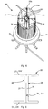
- a pole 100 for supporting lighting fixtures and other devices will be described below with reference to Figs. 1 to 17 .
- the same reference numerals are used in the different figures to denote the same or similar parts.
- the pole 100 comprises an elongate external covering 10 housing at least an upper portion of an elongate structural core 20 therein.
- the structural core 20 is preferably made of structural steel to serve as a structural element for bearing load of the pole 100 and anything else that may be provided on the pole 100, such as one or more lighting fixtures and other ICT devices.
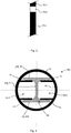
- the external covering 10 in general defines an elongate space 11, as shown in Fig. 1b , in which the structural core 20 as well as wiring (not shown) that may comprise electrical cabling and data cabling are housed. Electrical cabling is provided to power light fixtures (not shown) on the pole 100, while data cabling may be provided to connect ICT devices (not shown) on the pole 100 with a smart city or other desired network.
- the elongate space 11 defined by the external covering 10 is separated into a plural number of channels 40 by the structural core 20 housed in the external covering 10.
- the number of channels 40 provided in the pole 100 is determined by the cross-sectional shape of the structural core 20, as will be described in greater detail below.
- the structural core 20 comprises a number of longitudinally connected elongate plates 24 that define a plural number of channels 40 in the external covering 10.
- the structural core 20 may comprise an I-beam 20 comprising a vertical web 21 disposed between two parallel and spaced-apart horizontal flanges 22 to define an I-shaped cross-section.
- an I-beam is also known as an H-beam, Universal Beam (UB), or Rolled Steel Joist (RSJ) and the term "I-beam” is thus understood to also refer to such.
- UB Universal Beam
- RSJ Rolled Steel Joist
- the structural core 20 comprises an I-beam 20
- the I-beam is formed of three longitudinally connected elongate plates 24, wherein the three elongate plates 24 of the I-beam comprise the vertical web 21 and the two horizontal flanges 22.
- the term "I-beam” also refers to two U-shaped or C-shaped channels 29 connected back to back as shown in Fig. 9 , so that the two U-shaped or C-shaped channels 29 together effectively form an I-beam where the backs 28 of each of the two U-shaped or C-shaped channels 29 together define the vertical web 21 of the I-beam 20.
- the structural core 20 comprises four longitudinally connected and radially arranged plates 24 defining a cross-shaped cross-section defining four channels 40 within the external covering 10.
- the number of plates 24 is not confined to four and may be any desired number from three or more to form the desired number of channels 40 in the pole 100.
- the elongate plates 24 forming the structural core 20 may be longitudinally connected in a number of different ways.
- the structural core 20 may comprise two L-beams L1, L2 that are longitudinally connected along their angled bends.
- a first two 24-1, 24-2 of the number of plates 24 are provided by the first L-beam L1 and a second two 24-3, 24-4 of the number of plates 24 are provided by the second L-beam L2, so that the structural core 20 has a cross-shaped cross-section comprising four radially arranged elongate plates 24-1, 24-2, 24-3, 24-4.
- the structural core 20 may be configured to have a similar cross-shaped cross-section comprising four radially arranged elongate plates 24 by connecting two elongate plates 24-1, 24-2 onto the centre of each side of a wider central plate 25, so that the central plate 25 is divided into two and forms the remaining two plates 24-3, 24-4 that form the cross-shaped cross-section.
- the structural core 20 comprises three plates 24 longitudinally connected to form a Y-shaped cross-section defining three channels 40 in the pole 100 when assembled with the external covering 10.
- a structural core 20 having a T-shaped cross-section as shown in Fig. 12b may be formed by orthogonally connecting a first plate 24-1 onto a wider plate 25 that defines two further plates 24-2, 24-3 on each side of the first plate 24-1.
- the structural core 20 defines three channels 40-1, 40-2, 40-3 within the external covering 10 (shown schematically in dotted lines), in which one of the channels 40-1 is larger than the other two channels 40-2, 40-3.
- any conceivable configuration of the structural core 20 may be formed in order to define the plural number of channels 40 in the external covering 10.
- Fig 17 shows further exemplary alternative embodiments of the structural core 20 formed using a variety of different parts.
- the elongate space 11 is separated into two channels 40-1, 40-2 by at least the web 21 of the I-beam 20.
- the first channel 40-1 and the second channel 40-2 may be identical.
- the first and second channels 40-1, 40-2 allow electrical cabling and data cabling to be separately housed in different channels 40-1, 40-2 within the pole 100. Cables in the first channel 40-1 are electromagnetically shielded from cables in the second channel 40-2 by the web 21 of the I-beam 20. In this way, interference is minimized between electrical and data cabling that are simultaneously provided within the pole 100.
- the external covering 10 preferably comprises a number of longitudinally connected elongate panels 60 that are assembled to define a hollow cross-section to house the structural core 20 therein.
- the external covering 10 may comprise two curved panels 60 that each has a generally C-shaped cross-section to define a generally cylindrical external covering 10.
- the number of panels 60 may be two or more, and each panel 60 may be of any appropriate shape and size to enclose the structural core 20 therein when the panels 60 have been assembled together to form the external covering 10 of a desired exterior shape.
- the panels 60 may alternatively have L-shaped cross-sections (not shown).
- the panels 60 may be made of one or more appropriate materials, such as aluminium, steel, or polycarbonate where transparency may be desired.
- the panels 60 forming the external covering 10 may or may not be identical or similar in shape or size with one another.
- the number of panels 60 may correspond with the number of channels 40 provided in the pole 100 by configuring the panels 60 to be assembled around the structural core 20 such that each panel 60 is aligned with one channel 40. In this way, each of the number of channels 40 may be readily and individually accessed by removing an appropriate one of the number of panels 60 forming the external covering 10.
- connection of the longitudinal edges 60-1 of the panels 60 may be achieved using any appropriate known means (not shown), such as snap fit attachments, draw bolt latches, screw plates and so on.
- connection of the panels 60 of the external covering is configured to be releasable after assembly to allow for easy maintenance and reconfiguration of the pole 100 for different uses after installation.
- the pole 100 is readily assembled by laterally connecting the longitudinal edges 60-1 of the panels 60 around the erected structural core 20 as shown in Fig. 14 , thereby enclosing the structural core 20 within the external covering 10. This is a significantly easier method of assembling the pole compared to providing the external covering as an enclosed tube that must be raised until its bottom end is above a top end of the erected structural core in order for the external covering to be fitted over the structural core. Nevertheless, the external covering 10 may also be provided as a single tubular structure if so desired. In some embodiments, the pole 100 may comprise multiple sections 70 where the external covering 10 is made of different materials along its length. For example, as shown in Fig.
- the external covering 10 may comprise opaque aluminium sections 70-1 as well as a transparent polycarbonate section 70-2 where transparency is required to house a camera or other light receiving device (not shown) within one of the channels 40 of the pole 100.
- the external covering 10 is also formed of multiple panels 60 as described above, it will be understood that panels 60 of different materials used to form the different sections 70 will also be connected at their short edges in order to form the required length of external covering 10 of the pole 100, in addition to being connected at their longitudinal edges to other panels 60 of the external covering 10 to surround the structural core 20.
- the external covering 10 When the pole 100 is assembled, the external covering 10 preferably has a generally closed external cross-sectional shape to prevent wiring in the channels 40 from being exposed to the elements.
- the exemplary embodiment in Figs. 1b and 2 show the external covering 10 having a circular cross-section which presents the pole 100 as a cylinder.
- the external covering 10 may have an external cross-section of any other shape as may be desired, such as a rounded square, rounded rectangle, hexagon, and so on, as long as the elongate space 11 defined by the external covering 10 is of a sufficient size to house the structural core 20 and the desired wiring within the external covering 10.
- the external covering 10 may additionally be configured to comprise at least one longitudinal slot 62 provided along its length.
- the longitudinal slot 62 By configuring the longitudinal slot 62 to slideably and securably engage an arm 82 of the light fixture 80, easy raising and lowering of a light fixture 80 supported by the pole 100 (as indicated by the arrows) can be achieved for maintenance of the light fixture 80.
- the external covering 10 may further comprise internal guides 12 to engage the structural core 20.
- internal guides 12 help to secure the external covering 10 to the structural core 20 and to prevent movement of the external covering 10 relative to the structural core 20 when the external covering 10 and the structural core 20 have been assembled together.
- the internal guides 12 preferably comprise longitudinal ribs projecting from an inner surface 18 of the external covering 10.
- the internal guides 12 are preferably integral with the external covering 10, being likewise extruded, and may be of any appropriate size and shape to engage the lateral longitudinal edges of at least some of the elongate plates 24 of the structural core 20.
- Figs. 4 and 5 show different exemplary embodiments of the internal guides 12 and the wall 19 of the external covering 10.
- the internal guides 12 may comprise at least one straight rib to engage at least one side of a longitudinal edge of an elongate plate 24 of the structural core 20 as shown in Figs. 2 , 4 and 16 , or the internal guides 12 may comprise L-shaped ribs each provided to engage one side of an elongate plate 24 of the structural core 20 as shown in Fig. 5 .
- the pole 100 preferably further comprises a base 30 as shown in Figs. 6 to 8 .
- the base 30 provides structural rigidity and support to the pole 100 and is configured to be secured to the site where the pole 100 is installed.
- the base 30 comprises a base plate 31 provided at a bottom of the base 30.
- the base plate 31 has a central through hole for passing wiring therethrough from under the base 30.
- the base plate 31 is preferably made of steel.
- the base 30 also comprises an upstanding hollow central column 32 provided on the base plate 31.
- the central column 32 is preferably also made of steel.
- the central column 32 is preferably integral with the base plate 31, and may be welded to the base plate 31.
- the central column 32 is hollow to allow passage of cabling therethrough and to receive a bottom portion of the structural core 20 therein to keep the structural core 20 upright.
- the central column 32 may have a length of about 1 m when the structural core 20 has a length of about 6 m, so that about one-sixth of the structural core 20 is supported in the central column 32.
- the central column 32 preferably has a cross-sectional shape that is a rectangle or rounded rectangle, having an internal cavity sized and shaped to receive the structural core 20 with a clearance fit.
- the central column 32 may have a circular cross-sectional shape or any other cross-sectional shape that can suitably accommodate the structural core 20 therein.
- the base 30 may further comprise a casing 33 provided around and spaced apart from the central column 32 to enclose circuitry (not shown) provided in the base 30 as well as for aesthetic purposes.
- the casing 33 may be made of any appropriate material, for example, aluminium, steel, or a UV resistant polyethylene.
- the base 30 further comprises radial ribs 34 extending from the central column 32 to support the casing 33 as well as the external covering 10.
- An inner edge of each of the ribs 34 may be welded to the central column 32 and a bottom end of each rib 34 may be welded to the base plate 31.
- the ribs 34 are preferably equally angled apart from each other about the central column 32.
- the casing 33 contacts free longitudinal edges 34b of the ribs 34, so that the ribs 34 and the casing 33 together define a number of separate chambers 35 within the base 30.
- the separate chambers 35 allow separate sets of circuitry to be simultaneously housed in the base 30 in each of the separate chambers 35 respectively without interference with one another.
- the number of chambers 35 in the base 30 is equal to the number of ribs 34.
- At least two ribs 34 may be provided, preferably three or more.
- each rib 34 preferably extends above a top end of the central column 32 so that when the structural core 20 has been received in the central column 32 and the external covering 10 is assembled around the structural core 20, a bottom end of the external covering 10 rests on the top ends of the ribs 34, exposing a section of the structural core 20 below the bottom end of the external covering 10 in gaps 36 formed between the top end of the ribs 34 and the top end of the central column 32.
- bottom ends of the channels 40 in the pole 100 are open and accessible via the gaps 36. Cabling that passes through the base plate 31 and the central column 32 into the channels 40 may be accessed through the gaps 36 for connection to circuitry provided in the chambers 35 of the base 30.
- each rib 34 may be isolated from the other ribs.
- an inner edge at the top end of each rib 34 may be connected to a central hollow tube 39.
- the central hollow tube is preferably coaxial with the central column 32.
- the central hollow tube 39 has an internal cavity that is large enough for passage of the structural core 20 therethrough.
- a bottom end of the central hollow tube 39 is spaced apart from the top end of the central column 32 so that the gaps 36 for passage of cabling therethrough are provided below the bottom end of the central hollow tube 39.
- the central hollow tube 39 provides additional strength and rigidity to the ribs 34 for supporting the external covering 10 thereon.
- the central hollow tube 39 may have a circular cross-sectional shape or any other cross-sectional shape to allow passage of the structural core 20 therethrough and to support the external covering 10 thereon.
- the casing 33 may be provided as a plurality of separate sections 33a each having upstanding side edges 33b that engage the free longitudinal edges 34b of the ribs 34, as shown in Fig. 8 .
- the upstanding side edges 33b slideably engage the free longitudinal edges 34b of the ribs 34 while at a top end of the casing 33, hinged flaps 37 may be provided around the external covering 10, as shown in Fig. 6 .
- the hinged flaps 37 preferably pivot about hinges 38 having horizontal axes adjacent the external covering 10, so that each flap 36 may be lifted to allow a section 33a of the casing 33 to be raised. Raising a section 33a of the casing 33 creates an opening between a bottom edge 33c of the section 33a and the base plate 31, thereby gaining access to circuitry provided in a chamber 35 of the base 30.
- each of the hinged flaps 38 may be configured to be lockable so that its corresponding chamber 35 is accessible to only the relevant organization that is responsible for that particular fixture or device that has circuitry and other components stored in that particular chamber 35. In this way, unauthorized access can be prevented to minimize tampering and accidental damage to the components and circuitry stored in the base 30 of the pole 100.
- the upstanding side edges 33b of the separate sections 33a of the casing 33 may be releasably connected to the free longitudinal edges 34b of the radial ribs 34 via fittings (not shown) such as snap fit attachments, screw plates, draw bolt latches and so on, in order to allow the sections 33a to be individually removed for access to the chambers 35.
- the separate sections 33a may be hinged at their longitudinal edges to the longitudinal edges 34b of the radial ribs 34 in order for each section 33a to function as an openable door to access the chambers 35.
Landscapes
- Engineering & Computer Science (AREA)
- Architecture (AREA)
- Civil Engineering (AREA)
- Structural Engineering (AREA)
- Life Sciences & Earth Sciences (AREA)
- Chemical & Material Sciences (AREA)
- Materials Engineering (AREA)
- Wood Science & Technology (AREA)
- General Engineering & Computer Science (AREA)
- Non-Portable Lighting Devices Or Systems Thereof (AREA)
- Extrusion Moulding Of Plastics Or The Like (AREA)
- Road Signs Or Road Markings (AREA)
Claims (15)
- Mast (100) zum Tragen mindestens eines Beleuchtungskörpers (80) und mindestens eines Informations- und Kommunikationsgeräts auf demselben, wobei der Mast Folgendes umfasst:einen länglichen strukturellen Kern (20), um das Gewicht des Masts zu tragen,eine längliche äußere Abdeckung (10), die mindestens einen oberen Abschnitt des strukturellen Kerns in derselben aufnimmt, wobei der strukturelle Kern eine Vielzahl von Kanälen (40) innerhalb der äußeren Abdeckung definiert, um elektrische Verdrahtung, die in jedem der Anzahl von Kanälen bereitgestellt wird, zu trennen, undeine Basis (30), wobei die Basis Folgendes umfasst:eine Grundplatte (31), die ein mittiges Durchgangsloch zum Hindurchführen von Verkabelung durch dasselbe aufweist, wobei die Grundplatte dafür konfiguriert ist, an einem Ort befestigt zu werden, wo der Mast installiert wird, undeine aufrechte hohle mittige Säule (32), die auf der Grundplatte bereitgestellt wird, wobei ein unterer Abschnitt des strukturellen Kerns in der mittigen Säule aufgenommen wird,wobei die Basis ferner ein Gehäuse (33) umfasst, das um die mittige Säule und von derselben beabstandet bereitgestellt wird, undwobei die Basis ferner radiale Rippen (34) umfasst, die sich von der mittigen Säule aus erstrecken, um das Gehäuse zu stützen, wobei das Gehäuse freie Längskanten (34b) der radialen Rippen derart berührt, dass die radialen Rippen und das Gehäuse zusammen eine Anzahl von gesonderten Kammern (35) bilden, wobei die Anzahl von Kammern gleich der Anzahl von radialen Rippen ist.
- Mast nach Anspruch 1, wobei die äußere Abdeckung (10) mindestens zwei in Längsrichtung verbundene längliche Tafeln (60) umfasst.
- Mast nach einem der vorhergehenden Ansprüche, wobei die äußere Abdeckung (10) innere Führungen (12) umfasst, um den strukturellen Kern (20) in Eingriff zu nehmen.
- Mast nach Anspruch 3, wobei die inneren Führungen (12) Längsrippen umfassen, die von einer Innenfläche (18) der äußeren Abdeckung (10) aus vorspringen.
- Mast nach einem der vorhergehenden Ansprüche, wobei sich ein oberes Ende jeder der radialen Rippen (34) oberhalb eines oberen Endes der mittigen Säule (32) erstreckt.
- Mast nach Anspruch 5, wobei eine innere Kante an dem oberen Ende jeder der radialen Rippen (34) mit einer mittigen hohlen Röhre verbunden ist, wobei die mittige hohle Röhre (39) einen inneren Hohlraum aufweist, groß genug für einen Durchgang des strukturellen Kerns (20) durch dieselbe, wobei ein unteres Ende der mittigen hohlen Röhre von dem oberen Ende der mittigen Säule (32) beabstandet ist.
- Mast nach Anspruch 5 oder Anspruch 6, wobei ein unteres Ende der äußeren Abdeckung (10) auf dem oberen Ende jeder der radialen Rippen (34) ruht.
- Mast nach einem der vorhergehenden Ansprüche, wobei das Gehäuse (33) eine Vielzahl von gesonderten Sektionen (33a) umfasst, die jeweils aufrechte seitliche Kanten (33b) aufweisen, welche die freien Längskanten (34b) der radialen Rippen (34) in Eingriff nehmen.
- Mast nach Anspruch 8, wobei die aufrechten seitliche Kanten (33b) der Sektionen (33a) die freien Längskanten (34b) der radialen Rippen (34) verschiebbar in Eingriff nehmen und wobei der Mast (100) ferner angelenkte Klappen (37) umfasst, die um die äußere Abdeckung (10) an einem oberen Ende des Gehäuses (33) bereitgestellt werden, wobei ein Anheben einer der Klappen ermöglicht, dass eine entsprechende der Sektionen des Gehäuses hochgehoben wird und dadurch eine Öffnung zwischen einer unteren Kante der Sektion und der Basis (31) für einen Zugang zu einer entsprechenden der Kammern schafft.
- Mast nach Anspruch 9, wobei jede der angelenkten Klappen (37) verschließbar ist, um einen unbefugten Zugang zu jeder der Kammern (35) zu verhindern.
- Mast nach einem der vorhergehenden Ansprüche, wobei der strukturelle Kern (20) eine Anzahl von in Längsrichtung verbundenen länglichen Platten (24) umfasst.
- Mast nach Anspruch 11, wobei der strukturelle Kern (20) zwei Winkelträger (L1, L2) umfasst, wobei zwei erste der Platten (24) durch einen ersten der zwei Winkelträger definiert werden und zwei zweite der Platten durch einen zweiten der zwei Winkelträger definiert werden, wobei der strukturelle Kern einen kreuzförmigen Querschnitt aufweist.
- Mast nach Anspruch 11, wobei der strukturelle Kern (20) drei der Platten (24) umfasst, wobei der strukturelle Kern einen T-förmigen oder Y-förmigen Querschnitt aufweist und/oder wobei der strukturelle Kern einen Doppel-T-Träger umfasst, wobei ein Steg (21) des Doppel-T-Trägers und zwei Flansche (22) des Doppel-T-Trägers die in Längsrichtung verbundenen länglichen Platten bilden.
- Mast nach Anspruch 13, wobei der Doppel-T-Träger durch zwei U-förmige oder C-förmige Kanäle (29) gebildet wird, die Rücken an Rücken verbunden sind.
- Mast nach einem der vorhergehenden Ansprüche, wobei die äußere Abdeckung (10) einen Längsschlitz (62) umfasst, der entlang ihrer Länge bereitgestellt wird, um verschiebbar und feststellbar einen Arm (82) des mindestens einen Beleuchtungskörpers (80) in Eingriff zu nehmen.
Applications Claiming Priority (2)
| Application Number | Priority Date | Filing Date | Title |
|---|---|---|---|
| PCT/SG2017/050301 WO2018231146A1 (en) | 2017-06-14 | 2017-06-14 | Pole |
| PCT/SG2017/050433 WO2018231147A1 (en) | 2017-06-14 | 2017-08-31 | Pole for supporting lighting fixtures and other devices |
Publications (3)
| Publication Number | Publication Date |
|---|---|
| EP3542014A1 EP3542014A1 (de) | 2019-09-25 |
| EP3542014A4 EP3542014A4 (de) | 2020-08-19 |
| EP3542014B1 true EP3542014B1 (de) | 2021-04-07 |
Family
ID=64659205
Family Applications (1)
| Application Number | Title | Priority Date | Filing Date |
|---|---|---|---|
| EP17913186.7A Active EP3542014B1 (de) | 2017-06-14 | 2017-08-31 | Stange zum halten von leuchten und anderer vorrichtungen |
Country Status (8)
| Country | Link |
|---|---|
| US (1) | US10767825B2 (de) |
| EP (1) | EP3542014B1 (de) |
| CN (1) | CN110199070B (de) |
| AU (1) | AU2017279669B2 (de) |
| DK (1) | DK3542014T3 (de) |
| ES (1) | ES2880720T3 (de) |
| SG (1) | SG11201803245VA (de) |
| WO (2) | WO2018231146A1 (de) |
Families Citing this family (16)
| Publication number | Priority date | Publication date | Assignee | Title |
|---|---|---|---|---|
| GB2541960B (en) * | 2016-01-19 | 2018-02-21 | Hampton Steel Ltd | Fencing system |
| CN112292560A (zh) * | 2018-06-28 | 2021-01-29 | 昕诺飞控股有限公司 | 灯杆 |
| FR3083552B1 (fr) * | 2018-07-05 | 2021-03-05 | Valmont France | Dispositif de support comprenant un poteau |
| US11427976B2 (en) | 2018-07-17 | 2022-08-30 | Mccue Corporation | Barrier system and barrier system installation method |
| US10988954B2 (en) * | 2018-09-12 | 2021-04-27 | IPB Solution, Inc. | Pole base cabinet |
| US11124934B2 (en) * | 2019-05-28 | 2021-09-21 | Schram Management Company | Bollard assembly with stress control device |
| USD930189S1 (en) | 2019-07-17 | 2021-09-07 | Mccue Corporation | Bollard |
| CN110953518A (zh) * | 2019-07-27 | 2020-04-03 | 浙江互灵科技有限公司 | 一种模块化组合的户外照明设备及其安装方法 |
| SG11201910869RA (en) * | 2019-08-20 | 2021-03-30 | Photizo Global Pte Ltd | Pole |
| US20230032875A1 (en) * | 2020-01-22 | 2023-02-02 | Mccue Corporation | Barrier System and Barrier System Installation Method |
| WO2021206824A1 (en) * | 2020-04-07 | 2021-10-14 | Commscope Technologies Llc | Module for a telecommunications pole |
| WO2021253085A1 (en) * | 2020-06-16 | 2021-12-23 | Goodcart Pty Ltd | Pole assembly |
| CN111798748A (zh) * | 2020-08-19 | 2020-10-20 | 上海希林数字科技有限公司 | 一种银行展示装置 |
| CN112554630A (zh) * | 2020-10-28 | 2021-03-26 | 国家电网有限公司 | 一种电缆内嵌电线杆 |
| IT202200014647A1 (it) * | 2022-07-12 | 2024-01-12 | Alstom Holdings | Palo per il supporto di componenti di linee di alimentazione di mezzi di trasporto pubblico e/o di sistemi di illuminazione pubblica |
| TWI831726B (zh) * | 2023-09-06 | 2024-02-01 | 廈興國際股份有限公司 | 籬笆的邊柱結構改良 |
Family Cites Families (33)
| Publication number | Priority date | Publication date | Assignee | Title |
|---|---|---|---|---|
| US2808135A (en) * | 1951-01-30 | 1957-10-01 | Utility Pole Company | Metal pole structure and method |
| US3512819A (en) * | 1968-09-13 | 1970-05-19 | Foamcor Inc | Connector structure for modular panels and the like |
| LU82059A1 (fr) * | 1980-01-07 | 1980-04-23 | Reynolds Int Inc | Support pour objets divers et son procede de construction |
| US4429497A (en) * | 1981-04-10 | 1984-02-07 | Dibernardi Peter A | Pipe support system |
| US4991823A (en) * | 1990-04-26 | 1991-02-12 | Stanish Jr William A | Picket fence cap |
| US5568909A (en) * | 1995-03-10 | 1996-10-29 | Timko; Robert J. | Mounting bracket |
| US5632464A (en) * | 1995-09-05 | 1997-05-27 | Aberle; Steven C. | Ground pocket support |
| US6439744B1 (en) * | 1997-10-03 | 2002-08-27 | Yard-Lites, Inc. | Decorative ground lighting stake assembly and system |
| EP1068651B1 (de) | 1998-03-31 | 2004-03-03 | Vodafone Limited | Anordnung für zellulartelefon |
| US6467756B1 (en) * | 1998-05-20 | 2002-10-22 | Western Profiles Limited | Post and rail system using extrudable plastic posts |
| CN2354277Y (zh) * | 1998-09-08 | 1999-12-15 | 林正华 | 一种可走线分隔系统支柱 |
| US6330998B1 (en) * | 1999-05-06 | 2001-12-18 | Outdoor Technologies, L.L.C. | Plastic sheath products for studded steel T-posts, and production |
| JP2002348821A (ja) * | 2001-05-21 | 2002-12-04 | Imai Sumiko Design Jimusho Ikkyu Kenchikushi Jimusho:Kk | 統合コラム組織体 |
| US7500654B2 (en) * | 2002-05-28 | 2009-03-10 | Lars Rosaen | Fencing system |
| FR2841281B1 (fr) * | 2002-06-25 | 2004-09-17 | Rene Michel Verschuere | Elements de cloture incluant des profiles en h et des equerres de positionnement |
| US7490964B2 (en) * | 2002-10-09 | 2009-02-17 | Genlyte Thomas Group Llc | Modular pole system for a light fixture |
| US6851838B2 (en) * | 2002-10-09 | 2005-02-08 | Genlyte Thomas Group Llc | Modular pole system for a light fixture |
| GB0228990D0 (en) * | 2002-12-12 | 2003-01-15 | Simmonsigns Ltd | Posts |
| US6712330B1 (en) * | 2003-01-03 | 2004-03-30 | Valmont Industries, Inc. | Support pole |
| CA2449194C (en) * | 2003-11-12 | 2013-03-05 | Paul W. Fournier | Service line distribution base |
| CA2454776C (en) * | 2003-12-31 | 2007-10-02 | Nippon Steel Corporation | Steel pipe pole base and reinforcing method thereof |
| US7028991B2 (en) * | 2004-03-25 | 2006-04-18 | Egan Robert J | Lockable protective cap for posts |
| WO2007018962A2 (en) * | 2005-08-03 | 2007-02-15 | Gift Technologies, Lp | Composite poles and methods for forming the same |
| US8646735B2 (en) * | 2006-12-22 | 2014-02-11 | Seldon Bradley | Post mounting systems and accessories |
| US8113473B2 (en) * | 2006-12-22 | 2012-02-14 | Seldon Bradley | T-post and other mounting systems and accessories |
| US7731383B2 (en) | 2007-02-02 | 2010-06-08 | Inovus Solar, Inc. | Solar-powered light pole and LED light fixture |
| US8402717B1 (en) * | 2009-07-06 | 2013-03-26 | Lawrence Girard Randazzo | Wood hybrid light pole |
| CN201462618U (zh) * | 2009-07-24 | 2010-05-12 | 赵海波 | 升降式路灯 |
| US8919742B2 (en) * | 2010-09-10 | 2014-12-30 | Eastern Wholesale Fence Co., Inc. | System and fence kit for strengthening a fence |
| US20150070916A1 (en) * | 2013-09-11 | 2015-03-12 | Faisal A. Al-Asfour | Lighting poles with accessible electrics |
| US9732485B2 (en) * | 2015-01-23 | 2017-08-15 | Mccue Corporation | Column protector |
| CN107567525B (zh) * | 2015-01-31 | 2020-10-09 | 哨兵保护有限责任公司 | 柱保护器和柱保护系统 |
| CN204611676U (zh) * | 2015-05-21 | 2015-09-02 | 浙江环隆建设工程有限公司 | 一种路灯安装结构 |
-
2017
- 2017-06-14 WO PCT/SG2017/050301 patent/WO2018231146A1/en not_active Ceased
- 2017-08-31 WO PCT/SG2017/050433 patent/WO2018231147A1/en not_active Ceased
- 2017-08-31 SG SG11201803245VA patent/SG11201803245VA/en unknown
- 2017-08-31 AU AU2017279669A patent/AU2017279669B2/en active Active
- 2017-08-31 DK DK17913186.7T patent/DK3542014T3/da active
- 2017-08-31 US US15/749,861 patent/US10767825B2/en active Active
- 2017-08-31 EP EP17913186.7A patent/EP3542014B1/de active Active
- 2017-08-31 ES ES17913186T patent/ES2880720T3/es active Active
- 2017-08-31 CN CN201780083973.8A patent/CN110199070B/zh not_active Expired - Fee Related
Also Published As
| Publication number | Publication date |
|---|---|
| AU2017279669A1 (en) | 2019-01-17 |
| WO2018231147A1 (en) | 2018-12-20 |
| ES2880720T3 (es) | 2021-11-25 |
| DK3542014T3 (da) | 2021-07-12 |
| CN110199070A (zh) | 2019-09-03 |
| AU2017279669B2 (en) | 2022-10-13 |
| SG11201803245VA (en) | 2019-01-30 |
| EP3542014A4 (de) | 2020-08-19 |
| CN110199070B (zh) | 2021-05-25 |
| EP3542014A1 (de) | 2019-09-25 |
| US10767825B2 (en) | 2020-09-08 |
| US20200103085A1 (en) | 2020-04-02 |
| WO2018231146A1 (en) | 2018-12-20 |
Similar Documents
| Publication | Publication Date | Title |
|---|---|---|
| EP3542014B1 (de) | Stange zum halten von leuchten und anderer vorrichtungen | |
| EP3559380B1 (de) | Längliche struktur | |
| FI102926B (fi) | Laite erityisen informaation tuottamiseksi esimerkiksi varauloskäyntej ä varten | |
| US6128876A (en) | Tile panel system | |
| US8458961B2 (en) | Modular work station with air collector | |
| BR102013030331A2 (pt) | poste de iluminação com compartimento interno encaixado na sua base para equipamentos de telecomunicação | |
| US4273072A (en) | Prefabricated wall structure for forming an enclosure such as a horse-box | |
| EA023924B1 (ru) | Столб для ограждения | |
| AU755793B2 (en) | Method of partitioning office spaces | |
| JPH102006A (ja) | 建物の柵構造 | |
| JP7406225B2 (ja) | 組立構造体、及び組立構造体の製造方法 | |
| GB2425317A (en) | A kit for assembling a fence | |
| JP2011132742A (ja) | グリッド扉及びこれを用いたフェンス | |
| CN222253391U (zh) | 一种具有耳房结构的篷房支架及篷房 | |
| JP3143947U (ja) | 仮囲い | |
| US20250116132A1 (en) | Self standing enclosure for securing a production line and method for enclosing and securing a production line | |
| JP7199026B2 (ja) | 屋外用収納棚 | |
| DE20013446U1 (de) | Kabine mit wenigstens drei Seitenwänden und einem Dach | |
| KR200361475Y1 (ko) | 조립식 펜스 | |
| JPS61155566A (ja) | 建物の外廻り集合構築物 | |
| AU2012209019A1 (en) | A rail barrier | |
| KR200242890Y1 (ko) | 조립식 울타리 | |
| CA2238825C (en) | Tile panel system | |
| JP2022038854A (ja) | 建築用シャッター装置におけるシャッターカーテンの補強装置 | |
| KR20190128776A (ko) | 가설 가림막 구조체 |
Legal Events
| Date | Code | Title | Description |
|---|---|---|---|
| STAA | Information on the status of an ep patent application or granted ep patent |
Free format text: STATUS: THE INTERNATIONAL PUBLICATION HAS BEEN MADE |
|
| PUAI | Public reference made under article 153(3) epc to a published international application that has entered the european phase |
Free format text: ORIGINAL CODE: 0009012 |
|
| STAA | Information on the status of an ep patent application or granted ep patent |
Free format text: STATUS: REQUEST FOR EXAMINATION WAS MADE |
|
| 17P | Request for examination filed |
Effective date: 20190619 |
|
| AK | Designated contracting states |
Kind code of ref document: A1 Designated state(s): AL AT BE BG CH CY CZ DE DK EE ES FI FR GB GR HR HU IE IS IT LI LT LU LV MC MK MT NL NO PL PT RO RS SE SI SK SM TR |
|
| AX | Request for extension of the european patent |
Extension state: BA ME |
|
| REG | Reference to a national code |
Ref country code: HK Ref legal event code: DE Ref document number: 40008985 Country of ref document: HK |
|
| A4 | Supplementary search report drawn up and despatched |
Effective date: 20200720 |
|
| RIC1 | Information provided on ipc code assigned before grant |
Ipc: E04H 12/08 20060101ALI20200713BHEP Ipc: E04H 12/00 20060101AFI20200713BHEP Ipc: F21V 21/10 20060101ALI20200713BHEP Ipc: E04C 3/36 20060101ALI20200713BHEP |
|
| DAV | Request for validation of the european patent (deleted) | ||
| DAX | Request for extension of the european patent (deleted) | ||
| GRAP | Despatch of communication of intention to grant a patent |
Free format text: ORIGINAL CODE: EPIDOSNIGR1 |
|
| STAA | Information on the status of an ep patent application or granted ep patent |
Free format text: STATUS: GRANT OF PATENT IS INTENDED |
|
| INTG | Intention to grant announced |
Effective date: 20201221 |
|
| GRAS | Grant fee paid |
Free format text: ORIGINAL CODE: EPIDOSNIGR3 |
|
| GRAA | (expected) grant |
Free format text: ORIGINAL CODE: 0009210 |
|
| STAA | Information on the status of an ep patent application or granted ep patent |
Free format text: STATUS: THE PATENT HAS BEEN GRANTED |
|
| AK | Designated contracting states |
Kind code of ref document: B1 Designated state(s): AL AT BE BG CH CY CZ DE DK EE ES FI FR GB GR HR HU IE IS IT LI LT LU LV MC MK MT NL NO PL PT RO RS SE SI SK SM TR |
|
| REG | Reference to a national code |
Ref country code: GB Ref legal event code: FG4D |
|
| REG | Reference to a national code |
Ref country code: CH Ref legal event code: EP Ref country code: AT Ref legal event code: REF Ref document number: 1379880 Country of ref document: AT Kind code of ref document: T Effective date: 20210415 |
|
| REG | Reference to a national code |
Ref country code: DE Ref legal event code: R096 Ref document number: 602017036504 Country of ref document: DE |
|
| REG | Reference to a national code |
Ref country code: IE Ref legal event code: FG4D |
|
| REG | Reference to a national code |
Ref country code: FI Ref legal event code: FGE |
|
| REG | Reference to a national code |
Ref country code: DK Ref legal event code: T3 Effective date: 20210706 |
|
| REG | Reference to a national code |
Ref country code: NL Ref legal event code: FP |
|
| REG | Reference to a national code |
Ref country code: LT Ref legal event code: MG9D |
|
| REG | Reference to a national code |
Ref country code: SE Ref legal event code: TRGR |
|
| REG | Reference to a national code |
Ref country code: AT Ref legal event code: MK05 Ref document number: 1379880 Country of ref document: AT Kind code of ref document: T Effective date: 20210407 |
|
| PG25 | Lapsed in a contracting state [announced via postgrant information from national office to epo] |
Ref country code: HR Free format text: LAPSE BECAUSE OF FAILURE TO SUBMIT A TRANSLATION OF THE DESCRIPTION OR TO PAY THE FEE WITHIN THE PRESCRIBED TIME-LIMIT Effective date: 20210407 Ref country code: BG Free format text: LAPSE BECAUSE OF FAILURE TO SUBMIT A TRANSLATION OF THE DESCRIPTION OR TO PAY THE FEE WITHIN THE PRESCRIBED TIME-LIMIT Effective date: 20210707 Ref country code: AT Free format text: LAPSE BECAUSE OF FAILURE TO SUBMIT A TRANSLATION OF THE DESCRIPTION OR TO PAY THE FEE WITHIN THE PRESCRIBED TIME-LIMIT Effective date: 20210407 Ref country code: LT Free format text: LAPSE BECAUSE OF FAILURE TO SUBMIT A TRANSLATION OF THE DESCRIPTION OR TO PAY THE FEE WITHIN THE PRESCRIBED TIME-LIMIT Effective date: 20210407 |
|
| REG | Reference to a national code |
Ref country code: ES Ref legal event code: FG2A Ref document number: 2880720 Country of ref document: ES Kind code of ref document: T3 Effective date: 20211125 |
|
| PG25 | Lapsed in a contracting state [announced via postgrant information from national office to epo] |
Ref country code: GR Free format text: LAPSE BECAUSE OF FAILURE TO SUBMIT A TRANSLATION OF THE DESCRIPTION OR TO PAY THE FEE WITHIN THE PRESCRIBED TIME-LIMIT Effective date: 20210708 Ref country code: IS Free format text: LAPSE BECAUSE OF FAILURE TO SUBMIT A TRANSLATION OF THE DESCRIPTION OR TO PAY THE FEE WITHIN THE PRESCRIBED TIME-LIMIT Effective date: 20210807 Ref country code: PL Free format text: LAPSE BECAUSE OF FAILURE TO SUBMIT A TRANSLATION OF THE DESCRIPTION OR TO PAY THE FEE WITHIN THE PRESCRIBED TIME-LIMIT Effective date: 20210407 Ref country code: LV Free format text: LAPSE BECAUSE OF FAILURE TO SUBMIT A TRANSLATION OF THE DESCRIPTION OR TO PAY THE FEE WITHIN THE PRESCRIBED TIME-LIMIT Effective date: 20210407 Ref country code: PT Free format text: LAPSE BECAUSE OF FAILURE TO SUBMIT A TRANSLATION OF THE DESCRIPTION OR TO PAY THE FEE WITHIN THE PRESCRIBED TIME-LIMIT Effective date: 20210809 Ref country code: NO Free format text: LAPSE BECAUSE OF FAILURE TO SUBMIT A TRANSLATION OF THE DESCRIPTION OR TO PAY THE FEE WITHIN THE PRESCRIBED TIME-LIMIT Effective date: 20210707 Ref country code: RS Free format text: LAPSE BECAUSE OF FAILURE TO SUBMIT A TRANSLATION OF THE DESCRIPTION OR TO PAY THE FEE WITHIN THE PRESCRIBED TIME-LIMIT Effective date: 20210407 |
|
| REG | Reference to a national code |
Ref country code: DE Ref legal event code: R097 Ref document number: 602017036504 Country of ref document: DE |
|
| PG25 | Lapsed in a contracting state [announced via postgrant information from national office to epo] |
Ref country code: SM Free format text: LAPSE BECAUSE OF FAILURE TO SUBMIT A TRANSLATION OF THE DESCRIPTION OR TO PAY THE FEE WITHIN THE PRESCRIBED TIME-LIMIT Effective date: 20210407 Ref country code: SK Free format text: LAPSE BECAUSE OF FAILURE TO SUBMIT A TRANSLATION OF THE DESCRIPTION OR TO PAY THE FEE WITHIN THE PRESCRIBED TIME-LIMIT Effective date: 20210407 Ref country code: EE Free format text: LAPSE BECAUSE OF FAILURE TO SUBMIT A TRANSLATION OF THE DESCRIPTION OR TO PAY THE FEE WITHIN THE PRESCRIBED TIME-LIMIT Effective date: 20210407 Ref country code: RO Free format text: LAPSE BECAUSE OF FAILURE TO SUBMIT A TRANSLATION OF THE DESCRIPTION OR TO PAY THE FEE WITHIN THE PRESCRIBED TIME-LIMIT Effective date: 20210407 Ref country code: CZ Free format text: LAPSE BECAUSE OF FAILURE TO SUBMIT A TRANSLATION OF THE DESCRIPTION OR TO PAY THE FEE WITHIN THE PRESCRIBED TIME-LIMIT Effective date: 20210407 |
|
| PLBE | No opposition filed within time limit |
Free format text: ORIGINAL CODE: 0009261 |
|
| STAA | Information on the status of an ep patent application or granted ep patent |
Free format text: STATUS: NO OPPOSITION FILED WITHIN TIME LIMIT |
|
| 26N | No opposition filed |
Effective date: 20220110 |
|
| REG | Reference to a national code |
Ref country code: CH Ref legal event code: PL |
|
| PG25 | Lapsed in a contracting state [announced via postgrant information from national office to epo] |
Ref country code: MC Free format text: LAPSE BECAUSE OF FAILURE TO SUBMIT A TRANSLATION OF THE DESCRIPTION OR TO PAY THE FEE WITHIN THE PRESCRIBED TIME-LIMIT Effective date: 20210407 |
|
| REG | Reference to a national code |
Ref country code: BE Ref legal event code: MM Effective date: 20210831 |
|
| PG25 | Lapsed in a contracting state [announced via postgrant information from national office to epo] |
Ref country code: LI Free format text: LAPSE BECAUSE OF NON-PAYMENT OF DUE FEES Effective date: 20210831 Ref country code: CH Free format text: LAPSE BECAUSE OF NON-PAYMENT OF DUE FEES Effective date: 20210831 |
|
| PG25 | Lapsed in a contracting state [announced via postgrant information from national office to epo] |
Ref country code: IS Free format text: LAPSE BECAUSE OF FAILURE TO SUBMIT A TRANSLATION OF THE DESCRIPTION OR TO PAY THE FEE WITHIN THE PRESCRIBED TIME-LIMIT Effective date: 20210807 Ref country code: LU Free format text: LAPSE BECAUSE OF NON-PAYMENT OF DUE FEES Effective date: 20210831 Ref country code: AL Free format text: LAPSE BECAUSE OF FAILURE TO SUBMIT A TRANSLATION OF THE DESCRIPTION OR TO PAY THE FEE WITHIN THE PRESCRIBED TIME-LIMIT Effective date: 20210407 |
|
| PG25 | Lapsed in a contracting state [announced via postgrant information from national office to epo] |
Ref country code: IE Free format text: LAPSE BECAUSE OF NON-PAYMENT OF DUE FEES Effective date: 20210831 Ref country code: BE Free format text: LAPSE BECAUSE OF NON-PAYMENT OF DUE FEES Effective date: 20210831 |
|
| PG25 | Lapsed in a contracting state [announced via postgrant information from national office to epo] |
Ref country code: CY Free format text: LAPSE BECAUSE OF FAILURE TO SUBMIT A TRANSLATION OF THE DESCRIPTION OR TO PAY THE FEE WITHIN THE PRESCRIBED TIME-LIMIT Effective date: 20210407 |
|
| PG25 | Lapsed in a contracting state [announced via postgrant information from national office to epo] |
Ref country code: HU Free format text: LAPSE BECAUSE OF FAILURE TO SUBMIT A TRANSLATION OF THE DESCRIPTION OR TO PAY THE FEE WITHIN THE PRESCRIBED TIME-LIMIT; INVALID AB INITIO Effective date: 20170831 |
|
| PGFP | Annual fee paid to national office [announced via postgrant information from national office to epo] |
Ref country code: NL Payment date: 20230725 Year of fee payment: 7 |
|
| PGFP | Annual fee paid to national office [announced via postgrant information from national office to epo] |
Ref country code: IT Payment date: 20230704 Year of fee payment: 7 Ref country code: FI Payment date: 20230801 Year of fee payment: 7 Ref country code: ES Payment date: 20230905 Year of fee payment: 7 Ref country code: GB Payment date: 20230620 Year of fee payment: 7 |
|
| PGFP | Annual fee paid to national office [announced via postgrant information from national office to epo] |
Ref country code: SE Payment date: 20230816 Year of fee payment: 7 Ref country code: FR Payment date: 20230703 Year of fee payment: 7 Ref country code: DK Payment date: 20230817 Year of fee payment: 7 Ref country code: DE Payment date: 20230828 Year of fee payment: 7 |
|
| PG25 | Lapsed in a contracting state [announced via postgrant information from national office to epo] |
Ref country code: MK Free format text: LAPSE BECAUSE OF FAILURE TO SUBMIT A TRANSLATION OF THE DESCRIPTION OR TO PAY THE FEE WITHIN THE PRESCRIBED TIME-LIMIT Effective date: 20210407 |
|
| PG25 | Lapsed in a contracting state [announced via postgrant information from national office to epo] |
Ref country code: MT Free format text: LAPSE BECAUSE OF FAILURE TO SUBMIT A TRANSLATION OF THE DESCRIPTION OR TO PAY THE FEE WITHIN THE PRESCRIBED TIME-LIMIT Effective date: 20210407 |
|
| REG | Reference to a national code |
Ref country code: DE Ref legal event code: R119 Ref document number: 602017036504 Country of ref document: DE |
|
| REG | Reference to a national code |
Ref country code: DK Ref legal event code: EBP Effective date: 20240831 |
|
| REG | Reference to a national code |
Ref country code: NL Ref legal event code: MM Effective date: 20240901 |
|
| PG25 | Lapsed in a contracting state [announced via postgrant information from national office to epo] |
Ref country code: FI Free format text: LAPSE BECAUSE OF NON-PAYMENT OF DUE FEES Effective date: 20240831 |
|
| GBPC | Gb: european patent ceased through non-payment of renewal fee |
Effective date: 20240831 |
|
| REG | Reference to a national code |
Ref country code: SE Ref legal event code: EUG |
|
| PG25 | Lapsed in a contracting state [announced via postgrant information from national office to epo] |
Ref country code: NL Free format text: LAPSE BECAUSE OF NON-PAYMENT OF DUE FEES Effective date: 20240901 |
|
| PG25 | Lapsed in a contracting state [announced via postgrant information from national office to epo] |
Ref country code: DE Free format text: LAPSE BECAUSE OF NON-PAYMENT OF DUE FEES Effective date: 20250301 |
|
| PG25 | Lapsed in a contracting state [announced via postgrant information from national office to epo] |
Ref country code: DK Free format text: LAPSE BECAUSE OF NON-PAYMENT OF DUE FEES Effective date: 20240831 Ref country code: GB Free format text: LAPSE BECAUSE OF NON-PAYMENT OF DUE FEES Effective date: 20240831 |
|
| PG25 | Lapsed in a contracting state [announced via postgrant information from national office to epo] |
Ref country code: IT Free format text: LAPSE BECAUSE OF NON-PAYMENT OF DUE FEES Effective date: 20240831 |
|
| PG25 | Lapsed in a contracting state [announced via postgrant information from national office to epo] |
Ref country code: FR Free format text: LAPSE BECAUSE OF NON-PAYMENT OF DUE FEES Effective date: 20240831 |
|
| REG | Reference to a national code |
Ref country code: ES Ref legal event code: FD2A Effective date: 20251003 |
|
| PG25 | Lapsed in a contracting state [announced via postgrant information from national office to epo] |
Ref country code: ES Free format text: LAPSE BECAUSE OF NON-PAYMENT OF DUE FEES Effective date: 20240901 |
|
| PG25 | Lapsed in a contracting state [announced via postgrant information from national office to epo] |
Ref country code: SE Free format text: LAPSE BECAUSE OF NON-PAYMENT OF DUE FEES Effective date: 20240901 |
|
| PG25 | Lapsed in a contracting state [announced via postgrant information from national office to epo] |
Ref country code: TR Free format text: LAPSE BECAUSE OF FAILURE TO SUBMIT A TRANSLATION OF THE DESCRIPTION OR TO PAY THE FEE WITHIN THE PRESCRIBED TIME-LIMIT Effective date: 20210407 |
|
| REG | Reference to a national code |
Ref country code: HK Ref legal event code: WD Ref document number: 40008985 Country of ref document: HK |