EP3541319B1 - Laboranalogsystem - Google Patents
Laboranalogsystem Download PDFInfo
- Publication number
- EP3541319B1 EP3541319B1 EP17811453.4A EP17811453A EP3541319B1 EP 3541319 B1 EP3541319 B1 EP 3541319B1 EP 17811453 A EP17811453 A EP 17811453A EP 3541319 B1 EP3541319 B1 EP 3541319B1
- Authority
- EP
- European Patent Office
- Prior art keywords
- analog system
- laboratory analog
- insert post
- sleeve
- section
- Prior art date
- Legal status (The legal status is an assumption and is not a legal conclusion. Google has not performed a legal analysis and makes no representation as to the accuracy of the status listed.)
- Active
Links
Images


Classifications
-
- A—HUMAN NECESSITIES
- A61—MEDICAL OR VETERINARY SCIENCE; HYGIENE
- A61C—DENTISTRY; APPARATUS OR METHODS FOR ORAL OR DENTAL HYGIENE
- A61C8/00—Means to be fixed to the jaw-bone for consolidating natural teeth or for fixing dental prostheses thereon; Dental implants; Implanting tools
- A61C8/0001—Impression means for implants, e.g. impression coping
Definitions
- the present invention relates to a laboratory analog system having a sleeve and an insert post.
- a laboratory analog system is used for the spatial simulation of a connection and position of a dental implant in a plaster or plastic model. It is important that the spatial conditions within a molded set of teeth are reproduced as precisely as possible. In particular, the laboratory analog system should be mounted as firmly as possible and without play in order to be able to carry out a later reconstruction accurately.
- document EP 2 130 513 A1 discloses a system with an impression cap for transferring the position and orientation of an implant to an impression model.
- the system also includes an abutment having an annular bearing surface for placement within the impression cap.
- the object of claim 1 is achieved by a laboratory analog system for spatially simulating a position of a dental implant in an impression model.
- the laboratory analog system achieves the technical advantage, for example, that play is reduced and unintentional loosening of the used insert post is prevented.
- By the Locking radial movement of the spring portion prevents axial movement of the insert post.
- the securing element comprises a peripheral ring section for limiting an axial movement of the securing element.
- the securing element comprises a neck for blocking the radial movement of the spring section.
- the neck has a conical shape for exerting an increasing force on the spring section when the securing element is screwed in. This achieves the technical advantage, for example, that the spring section can be firmly pressed outwards by tightening the securing element.
- the securing element comprises a peripheral recess for accommodating the spring section in the release position.
- the spring section of the insert post comprises a support section for radial support on the securing element in the locked position.
- the support section has a wedge shape in cross section. This achieves the technical advantage, for example, that the blocking effect when screwing in the securing element is improved even further.
- the spring section is formed by two slots running in the axial direction in the insert post. This achieves the technical advantage, for example, that the spring section can be manufactured in a simple manner.
- the spring section includes a latching projection protruding outwards.
- the insert post comprises two opposing spring sections. This achieves the technical advantage, for example, that it is easier to insert the insert post into the sleeve.
- the insert post comprises a guide groove for guiding the insert post on a guide section when it is inserted into the sleeve.
- the sleeve comprises a projection running around the inside. This achieves the technical advantage, for example, that the spring section can act on the projection.
- the securing element includes a thread. This achieves the technical advantage, for example, that the securing element can be moved between the release position and the blocked position by turning.
- the securing element comprises a recess for inserting a turning tool, such as a hexagonal recess for a hexagonal key.
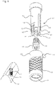
- the laboratory analog system 100 is used for spatial simulation of a connection and position of a dental implant in an impression model.
- the laboratory analog system 100 sits in the impression model 101 in the same position as the implant in the mouth.
- the laboratory analog system 100 is designed with a high level of precision.
- the laboratory analog system 100 includes a socket 103 and an insert post 107.
- the socket 103 is anchored in the dental impression model 101, such as a plaster or plastic model.
- the cylindrical sleeve 103 has a rhombic profile 129 on the outside with depressions into which the plaster of paris penetrates.
- the sleeve 103 has a lateral flattening 155, which is used for positioning when the sleeve 103 is glued into a model of the teeth that has been created with a corresponding opening based on a digital data set.
- the sleeve 103 can be anchored or fastened in the impression model 101 in a firm and non-rotatable manner.
- a cylindrical cavity is formed inside the sleeve 103.
- a pin-shaped guide section protrudes into this cavity is formed by a shaped body 115 inserted radially from the outside.
- the insertion post 107 is inserted coaxially into the cavity of the sleeve 103 and fixed by means of a locking screw 125 as a locking element.
- a locking screw 125 as a locking element.
- other securing elements can also be used as securing screws, such as a push-in pin.
- the inserted post 107 partially protrudes from the impression model 101 and includes a mechanical interface for an abutment.
- the insertion post 107 includes a guide groove 109.
- the guide section of the sleeve 103 slides within the guide groove 109 during insertion until it strikes the end of the guide groove 109.
- the insert post 107 can partially slide over the peripheral and inward projection 139 of the sleeve 103 during insertion.
- the projection 139 serves as a latching section for the spring sections 133.
- the projection 139 has a V-profile in cross section with two inclined surfaces. If the spring sections 133 are pressed outwards by the locking screw 125, an additional force is generated in the axial direction, which pulls the insert post 107 into the sleeve 103.
- the ring section 121 is delimited by a peripheral edge 123 . Due to the height of the ring portion 121, the Length and the spring action of the spring portion 131 are influenced.
- the ring section 121 has a conical shape, so that the ring section 121 can slide over the support section 143 when the locking screw 125 is screwed in for the first time.
- the inwardly projecting guide portion will abut the bottom edge 153 of the deployment post 107 and prevent further insertion. Only when the insert post 107 is rotated in such a way that the guide groove 109 is in agreement with the inner guide section of the sleeve 103 is further insertion of the insert post 107 possible. This ensures that the insert post 107 is always in the correct orientation in the end position.
- the insert post 107 also includes a pair of opposed spring portions 131 defined by axially extending slots 145 .
- the spring sections 131 are resiliently movable in the radial direction. When the insert post 107 is inserted into the sleeve 103, the spring sections 131 snap into place behind a circumferential projection 139 in the sleeve 103.
- the spring sections 131 each include a radially outwardly projecting latching projection 147 which, when inserted, slides over the peripheral projection 139 of the sleeve 103 and then snaps in behind the projection 139 .
- the latching projection 147 also has sloping surfaces which bear against the sloping surfaces of the V-profile of the projection 139 .
- the locking screw is tightened into a locking position, so that the spring sections 131 bear against the outside of the locking screw 125 and radial movement of the spring sections 131 inwards is blocked is. This secures the position of the deployment post 107 within the sleeve 103.
- the locking screw 125 is rotated to a release position allowing the spring portions 131 to move resiliently.
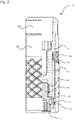
- FIG. 13 shows a partial cross-sectional view through the assembled laboratory analog system 100 with the insert post 107 and the sleeve 103.
- the insert post 107 is formed of a metal alloy or zircon and has, for example, a diameter of 3 mm and a height of 12 mm.
- the sleeve 107 is made of metal and has, for example, an inner diameter of 3 mm, an outer diameter of 4 mm and a height of 10 mm.
- the insert post 107 can serve as an adapter for the mechanical interfaces from different manufacturers.
- the locking screw 125 is in the locked position, in which radial movement of the spring sections 131 is prevented.
- the locking screw 131 includes a radially protruding circumferential ring section 135 which limits both screwing in and screwing out of the locking screw 125 .
- the ring section 135 is located in a circumferential recess 141 which forms an upper and a lower stop for the ring section 135 and serves to receive the radially inwardly bent spring sections 131 in the release position.
- the locking screw 125 includes a conical neck 137 as a support surface for the spring sections 131.
- the inwardly projecting guide section 105 is located in the guide groove 109, so that the insert post 107 is guided in the intended orientation during insertion.
- Figure 12 shows a cross-sectional view through the assembled laboratory analog system 100 with the locking screw 125 in the locked position.
- the locking screw In the locked position, the locking screw is in a screwed-in position. Screwing in of the locking screw 125 is limited by the circumferential ring section 135 which bears against the upper edge of the recess 141 .
- the wedge-shaped, inwardly projecting support section 143 bears against the conical neck 137 of the locking screw 125 and prevents the spring sections 131 from moving inwards.
- the conical neck 137 exerts a radially outward force on the spring portions 131 .
- the outward movement of the spring sections 131 is limited by the sleeve 103 .
- the locking projection 147 protruding outwards rests against the peripheral projection of the sleeve 103 .
- the spring sections 131 snap into place behind the peripheral projection 139 in a non-positive manner. This prevents the deployment post 107 from loosening from the sleeve 103 .
- the locking screw 125 is screwed into the insert post 107 with the thread 149 .
- the locking screw 125 includes a recess 151 for inserting a turning tool. As a result, the locking screw 125 can be tightened and loosened with a high torque.
- Figure 12 shows a cross-sectional view through the assembled laboratory analog system 100 with the locking screw 125 in the release position.
- the locking screw 125 In the release position, the locking screw 125 is in an unscrewed position. Further unscrewing of the locking screw 125 is limited by the peripheral ring section 135 which abuts the lower edge of the annular recess 141 . This prevents accidental loss of the locking screw 125 be prevented.
- the locking screw 125 is thereby captively mounted in the insert post 107 .
- the wedge-shaped, inwardly projecting support section 143 does not rest against the conical neck 137 of the locking screw 125, so that the spring sections 131 can move resiliently radially inwards. As a result, the spring sections 131 can slide over the circumferential projection 139 when the insert post 107 is pulled out, so that the insert post 107 can be released from the sleeve 103 .
- the locking screw 125 enables a firm and play-free connection between the insert post 107 and the sleeve 103 .
Landscapes
- Health & Medical Sciences (AREA)
- Oral & Maxillofacial Surgery (AREA)
- Orthopedic Medicine & Surgery (AREA)
- Dentistry (AREA)
- Epidemiology (AREA)
- Life Sciences & Earth Sciences (AREA)
- Animal Behavior & Ethology (AREA)
- General Health & Medical Sciences (AREA)
- Public Health (AREA)
- Veterinary Medicine (AREA)
- Dental Prosthetics (AREA)
- Dental Tools And Instruments Or Auxiliary Dental Instruments (AREA)
Description
- Die vorliegende Erfindung betrifft ein Laboranalogsystem mit einer Hülse und einem Einsatzpfosten.
- Ein Laboranalogsystem dient zur räumlichen Simulation einer Verbindung und Position eines Zahnimplantats in einem Gips- oder Kunststoffmodell. Dabei ist es wichtig, dass die räumlichen Gegebenheiten innerhalb eines abgeformten Gebisses möglichst genau wiedergegeben werden. Insbesondere sollte das Laboranalogsystem möglichst fest und ohne Spiel montiert werden, um eine spätere Rekonstruktion genau durchführen zu können.
- Dokument
EP 2 130 513 A1 offenbart ein System mit einer Abformkappe zur Übertragung der Position und Orientierung eines Implantats auf ein Abformmodell. Das System umfasst ferner ein Sekundärteil mit einer ringförmigen Auflagefläche zur Anordnung innerhalb der Abformkappe. - Es ist die Aufgabe der vorliegenden Erfindung, ein spielfreies Laboranalogsystem bereitzustellen.
- Diese Aufgabe wird durch den Gegenstand des unabhängigen Anspruchs 1 gelöst. Vorteilhafte Ausführungsformen sind Gegenstand der abhängigen Ansprüche, der Beschreibung und der Figuren.
- Erfindungsgemäß wird die Aufgabe gemäß Anspruch 1 durch ein Laboranalogsystem zur räumlichen Simulation einer Position eines Zahnimplantats in einem Abformmodell gelöst. Durch das Laboranalogsystem wird beispielsweise der technische Vorteil erreicht, dass ein Spiel verringert wird und ein unbeabsichtigtes Lösen des eingesetzten Einsatzpfostens verhindert wird. Durch das Sperren der radialen Bewegung des Federabschnitts wird eine axiale Bewegung des Einsatzpfostens verhindert.
- In einer vorteilhaften Ausführungsform des Laboranalogsystems umfasst das Sicherungselement einen umlaufenden Ringabschnitt zum Begrenzen einer axialen Bewegung des Sicherungselements. Dadurch wird beispielsweise der technische Vorteil erreicht, dass der Einsatzpfosten in jeder Orientierung fixiert werden kann.
- In einer weiteren vorteilhaften Ausführungsform des Laboranalogsystems umfasst das Sicherungselement einen Hals zum Sperren der radialen Bewegung des Federabschnitts. Dadurch wird beispielsweise der technische Vorteil erreicht, dass eine Freigabe des Einsatzpfostens wirksam gesperrt werden kann.
- In einer weiteren vorteilhaften Ausführungsform des Laboranalogsystems umfasst der Hals eine konische Form zum Ausüben einer zunehmenden Kraft auf den Federabschnitt beim Eindrehen des Sicherungselements. Dadurch wird beispielsweise der technische Vorteil erreicht, dass durch ein Anziehen des Sicherungselements der Federabschnitt fest nach Außen gedrückt werden kann.
- Erfindungsgemäß umfasst das Sicherungselement eine umlaufende Ausnehmung zum Aufnehmen des Federabschnitts in der Freigabeposition. Dadurch wird beispielsweise der technische Vorteil erreicht, dass eine kompakte Bauform des Laboranalogsystems erreicht wird.
- In einer weiteren vorteilhaften Ausführungsform des Laboranalogsystems umfasst der Federabschnitt des Einsatzpfostens einen Stützabschnitt zum radialen Abstützen an dem Sicherungselement in der Sperrposition. Dadurch wird beispielsweise der technische Vorteil erreicht, dass die Sperrwirkung des Federabschnitts verbessert wird.
- In einer weiteren vorteilhaften Ausführungsform des Laboranalogsystems west der Stützabschnitt im Querschnitt eine Keilform auf. Dadurch wird beispielsweise der technische Vorteil erreicht, dass die Sperrwirkung beim Eindrehen des Sicherungselements noch weiter verbessert wird.
- In einer weiteren vorteilhaften Ausführungsform des Laboranalogsystems wird der Federabschnitt durch zwei Schlitze gebildet, die in axialer Richtung in dem Einsatzpfosten verlaufen. Dadurch wird beispielsweise der technische Vorteil erreicht, dass sich der Federabschnitt auf einfache Weise herstellen lässt.
- In einer weiteren vorteilhaften Ausführungsform des Laboranalogsystems umfasst der Federabschnitt einen nach Außen stehenden Rastvorsprung. Dadurch wird beispielsweise der technische Vorteil erreicht, dass der Einsatzpfosten fest in der Hülse fixiert werden kann.
- In einer weiteren vorteilhaften Ausführungsform des Laboranalogsystems umfasst der Einsatzpfosten zwei gegenüberliegende Federabschnitte. Dadurch wird beispielsweise der technische Vorteil erreicht, dass ein Einsetzen des Einsatzpfostens in die Hülse erleichtert wird.
- In einer weiteren vorteilhaften Ausführungsform des Laboranalogsystems umfasst der Einsatzpfosten eine Führungsnut zum Führen des Einsatzpfostens an einem Führungsabschnitt beim Einsetzen in die Hülse. Dadurch wird beispielsweise der technische Vorteil erreicht, dass der Einsatzpfosten nur in einer vorgesehenen Orientierung eingesetzt werden kann.
- In einer weiteren vorteilhaften Ausführungsform des Laboranalogsystems umfasst die Hülse einen an der Innenseite umlaufenden Vorsprung. Dadurch wird beispielsweise der technische Vorteil erreicht, dass der Federabschnitt an dem Vorsprung angreifen kann.
- In einer weiteren vorteilhaften Ausführungsform des Laboranalogsystems umfasst das Sicherungselement ein Gewinde. Dadurch wird beispielsweise der technische Vorteil erreicht, dass das Sicherungselement durch Drehen zwischen der Freigabeposition und der Sperrposition bewegt werden kann.
- In einer weiteren vorteilhaften Ausführungsform des Laboranalogsystems umfasst das Sicherungselement eine Ausnehmung zum Einsetzen eines Drehwerkzeugs, wie beispielsweise eine sechseckige Ausnehmung für einen Sechskantschlüssel. Dadurch wird beispielsweise der technische Vorteil erreicht, dass das Sicherungselement auf einfache Weise angezogen werden kann.
- Ausführungsbeispiele der Erfindung sind in den Zeichnungen dargestellt und werden im Folgenden näher beschrieben.
- Es zeigen:
- Fig. 1
- eine Explosionsansicht eines Laboranalogsystems;
- Fig. 2
- eine Teilquerschnittsansicht durch das zusammengesetzte Laboranalogsystem;
- Fig. 3
- eine Querschnittsansicht durch das zusammengesetzte Laboranalogsystem in Sperrposition; und
- Fig. 4
- eine Querschnittsansicht durch das zusammengesetzte Laboranalogsystem in Freigabeposition.
-
Fig. 1 zeigt eine Explosionsansicht eines Laboranalogsystems 100. Das Laboranalogsystem 100 dient zur räumlichen Simulation einer Verbindung und Position eines Zahnimplantats in einem Abformmodell. Das Laboranalogsystem 100 sitzt im Abformmodell 101 an der gleichen Position wie das Implantat im Mund. Um die räumlichen Gegebenheiten möglichst exakt widerzugeben, ist das Laboranalogsystem 100 mit einer hohen Präzision ausgestaltet. - Das Laboranalogsystem 100 umfasst eine Hülse 103 und einen Einsatzpfosten 107. Die Hülse 103 wird in dem Abformmodell 101 des Gebisses verankert, wie beispielsweise einem Gips- oder Kunststoffmodell. Zu diesem Zweck weist die zylindrische Hülse 103 an der Außenseite eine rautenartige Profilierung 129 mit Vertiefungen auf, in die der Gips eindringt. Weiter weist die Hülse 103 eine seitliche Abflachung 155 auf, die zur Positionierung dient, wenn die Hülse 103 in ein Modell des Gebisses eingeklebt wird, das mit einer entsprechenden Öffnung nach einem digitalen Datensatz erstellt worden ist.
- Dadurch kann die Hülse 103 fest und verdrehsicher in dem Abformmodell 101 verankert oder befestigt werden. Im Inneren der Hülse 103 ist zylindrischer Hohlraum gebildet. In diesen Hohlraum ragt ein stiftförmiger Führungsabschnitt hinein, der durch einen radial von außen eingesetzten Formkörper 115 gebildet wird.
- Nach der Fertigung des Abformmodells 101 mit der Hülse 103 wird der Einsatzpfosten 107 in den Hohlraum der Hülse 103 koaxial eingesetzt und mittels einer Sicherungsschraube 125 als Sicherungselement fixiert. Im Allgemeinen können aber auch andere Sicherungselemente als Sicherungsschrauben verwendet werden, wie beispielsweise ein eindrückbarer Stift. Der eingesetzte Einsatzpfosten 107 ragt zum Teil aus dem Abformmodell 101 heraus und umfasst eine mechanische Schnittstelle für ein Abutment.
- Um ein orientierungsrichtiges Einsetzen des Einsatzpfostens 107 in die Hülse 103 zu ermöglichen, umfasst der Einsatzpfosten 107 eine Führungsnut 109. Der Führungsabschnitt der Hülse 103 gleitet beim Einführen innerhalb der Führungsnut 109 bis dieser am Ende der Führungsnut 109 anschlägt. Im unteren Bereich des Einsatzpfostens 107 ist ein Ringabschnitt 121 mit einem geringeren Außendurchmesser als im mittleren Bereich des Einsatzpfostens 107 angeordnet.
- Durch den Ringabschnitt 121 mit einem geringeren Außendurchmesser kann der Einsatzpfosten 107 beim Einsetzen teilweise über den umlaufenden und nach Innen stehenden Vorsprung 139 der Hülse 103 gleiten. Der Vorsprung 139 dient als Rastabschnitt für die Federabschnitte 133. Der Vorsprung 139 weist im Querschnitt ein V-Profil mit zwei schiefen Flächen auf. Werden die Federabschnitte 133 durch die Sicherungsschraube 125 nach außen gedrückt, entsteht zusätzlich eine Kraft in axialer Richtung, die den Einsatzpfosten 107 in die Hülse 103 zieht.
- Der Ringabschnitt 121 wird durch eine umlaufende Kante 123 begrenzt. Durch die Höhe des Ringabschnittes 121 kann die Länge und die Federwirkung des Federabschnitts 131 beeinflusst werden. Der Ringabschnitt 121 weist eine konische Form auf, so dass der Ringabschnitt 121 beim erstmaligen Eindrehen der Sicherungsschraube 125 über den Stützabschnitt 143 gleiten kann.
- Wird der Einsatzpfosten 107 in einer nicht-vorgesehen Orientierung eingesetzt, stößt der nach innen ragende Führungsabschnitt an der Unterkante 153 des Einsatzpfostens 107 an und verhindert ein weiteres Einschieben. Erst wenn der Einsatzpfosten 107 derart gedreht wird, dass die Führungsnut 109 in Übereinstimmung mit dem innen liegenden Führungsabschnitt der Hülse 103 ist, wird ein weiteres Einschieben des Einsatzpfostens 107 ermöglicht. Dadurch wird sichergestellt, dass sich der Einsatzpfosten 107 in der Endlage stets in der richtigen Orientierung befindet.
- Der Einsatzpfosten 107 umfasst zudem zwei gegenüberliegende Federabschnitte 131, die durch in axialer Richtung verlaufende Schlitze 145 gebildet werden. Die Federabschnitte 131 sind radialer Richtung federnd beweglich. Beim Einsetzen des Einsatzpfostens 107 in die Hülse 103 rasten die Federabschnitte 131 hinter einem umlaufenden Vorsprung 139 in der Hülse 103 ein. Zu diesem Zweck umfassen die Federabschnitte 131 jeweils einen radial nach Außen stehenden Rastvorsprung 147, der beim Einsetzen über umlaufenden Vorsprung 139 der Hülse 103 gleitet und danach hinter dem Vorsprung 139 in einschnappt. Der Rastvorsprung 147 weist ebenfalls schiefe Flächen auf, die an den schiefen Flächen des V-Profils des Vorsprungs 139 anliegen.
- In dieser Position wird die Sicherungsschraube in eine Sicherungsposition angezogen, so dass die Federabschnitte 131 an der Außenseite der Sicherungsschraube 125 anliegen und eine radiale Bewegung der Federabschnitte 131 nach Innen gesperrt ist. Dadurch wird die Position des Einsatzpfostens 107 in der Hülse 103 gesichert. Um den Einsatzpfostens 107 aus der Hülse 103 zu entfernen, wird die Sicherungsschraube 125 in eine Freigabeposition gedreht, in der eine federnde Bewegung der Federabschnitte 131 ermöglicht wird.
-
Fig. 2 zeigt eine Teilquerschnittsansicht durch das zusammengesetzte Laboranalogsystem 100 mit dem Einsatzpfosten 107 und der Hülse 103. Der Einsatzpfosten 107 ist aus einer Metalllegierung oder Zirkon gebildet und weist beispielsweise einen Durchmesser von 3 mm und eine Höhe von 12 mm auf. Die Hülse 107 ist aus Metall gebildet und weist beispielsweise einen Innendurchmesser von 3 mm, einen Außendurchmesser von 4 mm und eine Höhe von 10 mm auf. Der Einsatzpfosten 107 kann als Adapter für die mechanischen Schnittstellen von unterschiedlichen Herstellern dienen. - Die Sicherungsschraube 125 befindet sich in der Sperrposition, in der eine radial Bewegung der Federabschnitte 131 verhindert wird. Die Sicherungsschraube 131 umfasst einen radial abstehenden umlaufenden Ringabschnitt 135, der sowohl ein Eindrehen als auch ein Herausdrehen der Sicherungsschraube 125 begrenzt. Der Ringabschnitt 135 befindet sich in einer umlaufenden Ausnehmung 141, die einen oberen und einen unteren Anschlag für den Ringabschnitt 135 bildet und zum Aufnehmen der radial nach Innen gebogenen Federabschnitte 131 in der Freigabeposition dient. Die Sicherungsschraube 125 umfasst einen konischen Hals 137 als Stützfläche für die Federabschnitte 131.
- Der nach innen ragende Führungsabschnitt 105 befindet sich in der Führungsnut 109, so dass der Einsatzpfosten 107 in der vorgesehenen Orientierung beim Einsetzen geführt wird.
-
Fig. 3 zeigt eine Querschnittsansicht durch das zusammengesetzte Laboranalogsystem 100 mit der Sicherungsschraube 125 in Sperrposition. In der Sperrposition ist die Sicherungsschraube in einer eingedrehten Stellung. Ein Eindrehen der Sicherungsschraube 125 wird durch den umlaufenden Ringabschnitt 135 begrenzt, der an der oberen Kante der Ausnehmung 141 anliegt. - Der keilförmige, nach Innen ragende Stützabschnitt 143 liegt am konischen Hals 137 der Sicherungsschraube 125 an und verhindert die Bewegung der Federabschnitte 131 nach Innen. Der konische Hals 137 übt auf die Federabschnitte 131 eine radial nach außen wirkende Kraft aus. Nach außen hin ist die Bewegung der Federabschnitte 131 durch die Hülse 103 begrenzt. Der nach Außen stehende Rastvorsprung 147 liegt an dem umlaufenden Vorsprung der Hülse 103 an. Die Federabschnitte 131 rasten kraftschlüssig hinter dem umlaufenden Vorsprung 139 ein. Dadurch wird ein Lösen des Einsatzpfostens 107 aus der Hülse 103 verhindert.
- Die Sicherungsschraube 125 ist mit dem Gewinde 149 in den Einsatzpfosten 107 eingedreht. Die Sicherungsschraube 125 umfasst eine Ausnehmung 151 zum Einsetzen eines Drehwerkzeugs. Dadurch kann die Sicherungsschraube 125 mit einem hohen Drehmoment angezogen und gelöst werden.
-
Fig. 4 zeigt eine Querschnittsansicht durch das zusammengesetzte Laboranalogsystem 100 mit der Sicherungsschraube 125 in Freigabeposition. In der Freigabeposition ist die Sicherungsschraube 125 in einer herausgedrehten Stellung. Ein weiteres Herausdrehen der Sicherungsschraube 125 wird durch den umlaufenden Ringabschnitt 135 begrenzt, der an der unteren Kante der ringförmigen Ausnehmung 141 anliegt. Dadurch kann ein unbeabsichtigtes Verlieren der Sicherungsschraube 125 verhindert werden. Die Sicherungsschraube 125 ist dadurch verliersicher in dem Einsatzpfosten 107 gelagert. - Der keilförmige, nach Innen ragende Stützabschnitt 143 liegt nicht am konischen Hals 137 der Sicherungsschraube 125 an, so dass sich die Federabschnitte 131 federnd radial nach Innen bewegen können. Dadurch können die Federabschnitte 131 beim Herausziehen des Einsatzpfostens 107 über den umlaufenden Vorsprung 139 gleiten, so dass ein Lösen des Einsatzpfostens 107 aus der Hülse 103 ermöglicht wird.
- Durch die Sicherungsschraube 125 wird eine feste und spielfreie Verbindung zwischen dem Einsatzpfosten 107 und der Hülse 103 ermöglicht.
-
- 100
- Laboranalogsystem
- 101
- Abformmodell
- 103
- Hülse
- 105
- Führungsabschnitt
- 107
- Einsatzpfosten
- 109
- Führungsnut
- 115
- Formkörper
- 121
- Ringabschnitt
- 123
- Kante
- 125
- Sicherungselement/Sicherungsschraube
- 129
- Profilierung
- 131
- Federabschnitt
- 135
- Ringabschnitt
- 137
- Hals
- 139
- Vorsprung
- 141
- Ausnehmung
- 143
- Stützabschnitt
- 145
- Schlitz
- 147
- Rastvorsprung
- 149
- Gewinde
- 151
- Ausnehmung
- 153
- Unterkante
- 155
- Abflachung
Claims (13)
- Laboranalogsystem (100) zur räumlichen Simulation einer Position eines Zahnimplantats in einem Abformmodell (101), mit:- einer Hülse (103);- einem Einsatzpfosten (107) mit zumindest einem radial beweglichen Federabschnitt (131) zum Einrasten an der den Einsatzpfosten (107) umgebenden Hülse (103); und- einem beweglichen Sicherungselement (125) zum Sperren einer radialen Bewegung des Federabschnitts (131) in einer Sicherungsposition, das eine umlaufende Ausnehmung (141) zum Aufnehmen des Federabschnitts (131) in einer Freigabeposition, in welcher der Einsatzpfosten aus der Hülse entfernbar ist, umfasst.
- Laboranalogsystem (100) nach Anspruch 1, wobei das Sicherungselement (125) einen umlaufenden Ringabschnitt (135) zum Begrenzen einer axialen Bewegung des Sicherungselements (125) umfasst.
- Laboranalogsystem (100) nach einem der vorangehenden Ansprüche, wobei das Sicherungselement (125) einen Hals (137) zum Sperren der radialen Bewegung des Federabschnitts (131) umfasst.
- Laboranalogsystem (100) nach Anspruch 3, wobei der Hals (137) eine konische Form zum Ausüben einer zunehmenden Kraft auf den Federabschnitt beim Eindrehen des Sicherungselements (125) umfasst.
- Laboranalogsystem (100) nach einem der vorangehenden Ansprüche, wobei der Federabschnitt (131) des Einsatzpfostens (107) einen Stützabschnitt (143) zum radialen Abstützen an dem Sicherungselement (125) in der Sperrposition umfasst.
- Laboranalogsystem (100) nach Anspruch 5, wobei der Stützabschnitt (143) im Querschnitt eine Keilform aufweist.
- Laboranalogsystem (100) nach einem der vorangehenden Ansprüche, wobei der Federabschnitt (131) durch zwei Schlitze (145) gebildet wird, die in axialer Richtung in dem Einsatzpfosten (107) verlaufen.
- Laboranalogsystem (100) nach einem der vorangehenden Ansprüche, wobei der Federabschnitt (131) einen nach Außen stehenden Rastvorsprung (147) umfasst.
- Laboranalogsystem (100) nach einem der vorangehenden Ansprüche, wobei der Einsatzpfosten (107) zwei gegenüberliegende Federabschnitte (131) umfasst.
- Laboranalogsystem (100) nach einem der vorangehenden Ansprüche, wobei der Einsatzpfosten (107) eine Führungsnut (109) zum Führen des Einsatzpfostens (107) an einem Führungsabschnitt (105) beim Einsetzen in die Hülse (103) umfasst.
- Laboranalogsystem (100) nach einem der vorangehenden Ansprüche, wobei die Hülse (103) einen an der Innenseite umlaufenden Vorsprung (139) umfasst.
- Laboranalogsystem (100) nach einem der vorangehenden Ansprüche, wobei das Sicherungselement (125) ein Gewinde (149) umfasst.
- Laboranalogsystem (100) nach einem der vorangehenden Ansprüche, wobei das Sicherungselement (125) eine Ausnehmung (151) zum Einsetzen eines Drehwerkzeugs umfasst.
Applications Claiming Priority (2)
| Application Number | Priority Date | Filing Date | Title |
|---|---|---|---|
| DE102016122203.8A DE102016122203B4 (de) | 2016-11-18 | 2016-11-18 | Laboranalogsystem |
| PCT/EP2017/079278 WO2018091505A1 (de) | 2016-11-18 | 2017-11-15 | Laboranalogsystem |
Publications (2)
| Publication Number | Publication Date |
|---|---|
| EP3541319A1 EP3541319A1 (de) | 2019-09-25 |
| EP3541319B1 true EP3541319B1 (de) | 2022-04-06 |
Family
ID=60629636
Family Applications (1)
| Application Number | Title | Priority Date | Filing Date |
|---|---|---|---|
| EP17811453.4A Active EP3541319B1 (de) | 2016-11-18 | 2017-11-15 | Laboranalogsystem |
Country Status (4)
| Country | Link |
|---|---|
| EP (1) | EP3541319B1 (de) |
| DE (1) | DE102016122203B4 (de) |
| ES (1) | ES2921677T3 (de) |
| WO (1) | WO2018091505A1 (de) |
Cited By (1)
| Publication number | Priority date | Publication date | Assignee | Title |
|---|---|---|---|---|
| EP4483836A1 (de) * | 2023-06-26 | 2025-01-01 | Heinrich Steger | Dentalanalog |
Families Citing this family (1)
| Publication number | Priority date | Publication date | Assignee | Title |
|---|---|---|---|---|
| EP4438003B1 (de) * | 2023-03-27 | 2026-01-14 | Vogul, S.L.U. | Vorrichtung zur digitalisierung und herstellung von zahnmodellen |
Citations (1)
| Publication number | Priority date | Publication date | Assignee | Title |
|---|---|---|---|---|
| US5782918A (en) * | 1996-12-12 | 1998-07-21 | Folsom Metal Products | Implant abutment system |
Family Cites Families (9)
| Publication number | Priority date | Publication date | Assignee | Title |
|---|---|---|---|---|
| US5004421A (en) * | 1990-07-27 | 1991-04-02 | Sargon Lazarof | Dental implant and method of using same |
| US5681167A (en) * | 1996-01-05 | 1997-10-28 | Lazarof; Sargon | Dental assembly and process for preparing a tooth prosthesis |
| DE19646307A1 (de) * | 1996-11-09 | 1998-05-14 | Ralf Dr Schroeder | Kieferschraubenimplantat |
| US7018207B2 (en) * | 2002-02-22 | 2006-03-28 | Implant Innovations, Inc. | Dental implant analog having retention groove for soft tissue modeling |
| DE202006017574U1 (de) * | 2006-11-14 | 2008-03-27 | Biomed Est. | Reponierbares Implantatanalog |
| ATE500797T1 (de) * | 2007-01-18 | 2011-03-15 | Straumann Holding Ag | Abformkappe |
| EP2130513A1 (de) * | 2008-06-06 | 2009-12-09 | Straumann Holding AG | Vorrichtung zum Anbringen einer Abformkappe an einem Zahnimplantat |
| DE202013001642U1 (de) * | 2013-02-13 | 2013-02-27 | Rainer Manfred Hettrich | Modell-Implantat zweiteilig, gerade oder abgewinkelt zur Herstellung von implantatgetragenem Zahnersatz auf digitalem oder herkömmlichen Wege |
| DE102014106076A1 (de) * | 2014-04-30 | 2015-11-05 | Michael Augthun | Zahnmedizinisches Implantat |
-
2016
- 2016-11-18 DE DE102016122203.8A patent/DE102016122203B4/de active Active
-
2017
- 2017-11-15 WO PCT/EP2017/079278 patent/WO2018091505A1/de not_active Ceased
- 2017-11-15 ES ES17811453T patent/ES2921677T3/es active Active
- 2017-11-15 EP EP17811453.4A patent/EP3541319B1/de active Active
Patent Citations (1)
| Publication number | Priority date | Publication date | Assignee | Title |
|---|---|---|---|---|
| US5782918A (en) * | 1996-12-12 | 1998-07-21 | Folsom Metal Products | Implant abutment system |
Cited By (1)
| Publication number | Priority date | Publication date | Assignee | Title |
|---|---|---|---|---|
| EP4483836A1 (de) * | 2023-06-26 | 2025-01-01 | Heinrich Steger | Dentalanalog |
Also Published As
| Publication number | Publication date |
|---|---|
| ES2921677T3 (es) | 2022-08-30 |
| DE102016122203B4 (de) | 2019-09-26 |
| EP3541319A1 (de) | 2019-09-25 |
| DE102016122203A1 (de) | 2018-05-24 |
| WO2018091505A1 (de) | 2018-05-24 |
Similar Documents
| Publication | Publication Date | Title |
|---|---|---|
| EP2303180B1 (de) | Vorrichtung zum anbringen einer abformkappe an einem zahnimplantat | |
| DE2521573C3 (de) | Stumpfmodellstift mit Steckhälse | |
| EP0005865A2 (de) | Steckbares Verbindungssystem für Druckleitungen, insbesondere Bremssystem-Leitungen | |
| DE102009015358B4 (de) | Schraube, Schraubwerkzeug und deren Verwendung zur Herstellung von Zahnprothesen | |
| DE212007000106U1 (de) | Anordnung zur Bildung einer Stegkonstuktion und Fixationsschraube dafür | |
| EP2862542A1 (de) | Retentionsmatrize und Dentalimplantatsystem | |
| EP0132673B1 (de) | Verbindungsvorrichtung für Druckleitungen | |
| EP1651133B1 (de) | Implantatteil für ein zahnimplantat | |
| EP4162188B1 (de) | Vorrichtung zum verbinden zweier röhrenförmiger objekte | |
| DE102005027184A1 (de) | Modellimplantat für Zahnimplantate | |
| DE102015120525B4 (de) | Befestigungssystem für einen Toilettensitz, Käfig, Käfigmutter, Verwendung, Anordnung und Verfahren | |
| DE102016122203B4 (de) | Laboranalogsystem | |
| EP3091240A1 (de) | Vorrichtung und anordnung zur verriegelung von schraubbaren elementen | |
| EP3215048B1 (de) | Abutmentaufsatz | |
| EP0185802A1 (de) | Verbindungsvorrichtung für Druckleitungen mit unverlierbarem Haltering | |
| WO2018041577A1 (de) | Kippsegmentlager | |
| WO2018091506A1 (de) | Scankörper für ein laboranalogsystem | |
| DE102005062194A1 (de) | Nivellierteller | |
| DE102019100175B4 (de) | Abutmentaufsatzsystem, Scankopf und Abformkappe | |
| DE102015100509B4 (de) | Transfer-Schablone | |
| DE202009009500U1 (de) | Schraubprofil für den Einsatz bei Zahnimplantaten, insbesondere Abutmentschraube oder Gingivaformer | |
| DE102009008291A1 (de) | Abdruckkappe mit Abdruckpfosten für ein Zahnimplantat | |
| DE202019105013U1 (de) | Abformpfosten für ein Dentalimplantat | |
| DE102018119612A1 (de) | Abutmentsystem | |
| EP3375404A1 (de) | Sekundärteil für ein dentalimplantat und dentales implantatset |
Legal Events
| Date | Code | Title | Description |
|---|---|---|---|
| STAA | Information on the status of an ep patent application or granted ep patent |
Free format text: STATUS: UNKNOWN |
|
| STAA | Information on the status of an ep patent application or granted ep patent |
Free format text: STATUS: THE INTERNATIONAL PUBLICATION HAS BEEN MADE |
|
| PUAI | Public reference made under article 153(3) epc to a published international application that has entered the european phase |
Free format text: ORIGINAL CODE: 0009012 |
|
| STAA | Information on the status of an ep patent application or granted ep patent |
Free format text: STATUS: REQUEST FOR EXAMINATION WAS MADE |
|
| 17P | Request for examination filed |
Effective date: 20190614 |
|
| AK | Designated contracting states |
Kind code of ref document: A1 Designated state(s): AL AT BE BG CH CY CZ DE DK EE ES FI FR GB GR HR HU IE IS IT LI LT LU LV MC MK MT NL NO PL PT RO RS SE SI SK SM TR |
|
| AX | Request for extension of the european patent |
Extension state: BA ME |
|
| DAV | Request for validation of the european patent (deleted) | ||
| DAX | Request for extension of the european patent (deleted) | ||
| STAA | Information on the status of an ep patent application or granted ep patent |
Free format text: STATUS: EXAMINATION IS IN PROGRESS |
|
| 17Q | First examination report despatched |
Effective date: 20200515 |
|
| GRAP | Despatch of communication of intention to grant a patent |
Free format text: ORIGINAL CODE: EPIDOSNIGR1 |
|
| STAA | Information on the status of an ep patent application or granted ep patent |
Free format text: STATUS: GRANT OF PATENT IS INTENDED |
|
| INTG | Intention to grant announced |
Effective date: 20211210 |
|
| GRAS | Grant fee paid |
Free format text: ORIGINAL CODE: EPIDOSNIGR3 |
|
| GRAA | (expected) grant |
Free format text: ORIGINAL CODE: 0009210 |
|
| STAA | Information on the status of an ep patent application or granted ep patent |
Free format text: STATUS: THE PATENT HAS BEEN GRANTED |
|
| AK | Designated contracting states |
Kind code of ref document: B1 Designated state(s): AL AT BE BG CH CY CZ DE DK EE ES FI FR GB GR HR HU IE IS IT LI LT LU LV MC MK MT NL NO PL PT RO RS SE SI SK SM TR |
|
| REG | Reference to a national code |
Ref country code: GB Ref legal event code: FG4D Free format text: NOT ENGLISH |
|
| REG | Reference to a national code |
Ref country code: CH Ref legal event code: EP |
|
| REG | Reference to a national code |
Ref country code: AT Ref legal event code: REF Ref document number: 1480590 Country of ref document: AT Kind code of ref document: T Effective date: 20220415 |
|
| REG | Reference to a national code |
Ref country code: IE Ref legal event code: FG4D Free format text: LANGUAGE OF EP DOCUMENT: GERMAN |
|
| REG | Reference to a national code |
Ref country code: DE Ref legal event code: R096 Ref document number: 502017012931 Country of ref document: DE |
|
| REG | Reference to a national code |
Ref country code: LT Ref legal event code: MG9D |
|
| REG | Reference to a national code |
Ref country code: NL Ref legal event code: MP Effective date: 20220406 |
|
| REG | Reference to a national code |
Ref country code: ES Ref legal event code: FG2A Ref document number: 2921677 Country of ref document: ES Kind code of ref document: T3 Effective date: 20220830 |
|
| PG25 | Lapsed in a contracting state [announced via postgrant information from national office to epo] |
Ref country code: NL Free format text: LAPSE BECAUSE OF FAILURE TO SUBMIT A TRANSLATION OF THE DESCRIPTION OR TO PAY THE FEE WITHIN THE PRESCRIBED TIME-LIMIT Effective date: 20220406 |
|
| PG25 | Lapsed in a contracting state [announced via postgrant information from national office to epo] |
Ref country code: SE Free format text: LAPSE BECAUSE OF FAILURE TO SUBMIT A TRANSLATION OF THE DESCRIPTION OR TO PAY THE FEE WITHIN THE PRESCRIBED TIME-LIMIT Effective date: 20220406 Ref country code: PT Free format text: LAPSE BECAUSE OF FAILURE TO SUBMIT A TRANSLATION OF THE DESCRIPTION OR TO PAY THE FEE WITHIN THE PRESCRIBED TIME-LIMIT Effective date: 20220808 Ref country code: NO Free format text: LAPSE BECAUSE OF FAILURE TO SUBMIT A TRANSLATION OF THE DESCRIPTION OR TO PAY THE FEE WITHIN THE PRESCRIBED TIME-LIMIT Effective date: 20220706 Ref country code: LT Free format text: LAPSE BECAUSE OF FAILURE TO SUBMIT A TRANSLATION OF THE DESCRIPTION OR TO PAY THE FEE WITHIN THE PRESCRIBED TIME-LIMIT Effective date: 20220406 Ref country code: HR Free format text: LAPSE BECAUSE OF FAILURE TO SUBMIT A TRANSLATION OF THE DESCRIPTION OR TO PAY THE FEE WITHIN THE PRESCRIBED TIME-LIMIT Effective date: 20220406 Ref country code: GR Free format text: LAPSE BECAUSE OF FAILURE TO SUBMIT A TRANSLATION OF THE DESCRIPTION OR TO PAY THE FEE WITHIN THE PRESCRIBED TIME-LIMIT Effective date: 20220707 Ref country code: FI Free format text: LAPSE BECAUSE OF FAILURE TO SUBMIT A TRANSLATION OF THE DESCRIPTION OR TO PAY THE FEE WITHIN THE PRESCRIBED TIME-LIMIT Effective date: 20220406 Ref country code: BG Free format text: LAPSE BECAUSE OF FAILURE TO SUBMIT A TRANSLATION OF THE DESCRIPTION OR TO PAY THE FEE WITHIN THE PRESCRIBED TIME-LIMIT Effective date: 20220706 |
|
| PG25 | Lapsed in a contracting state [announced via postgrant information from national office to epo] |
Ref country code: RS Free format text: LAPSE BECAUSE OF FAILURE TO SUBMIT A TRANSLATION OF THE DESCRIPTION OR TO PAY THE FEE WITHIN THE PRESCRIBED TIME-LIMIT Effective date: 20220406 Ref country code: PL Free format text: LAPSE BECAUSE OF FAILURE TO SUBMIT A TRANSLATION OF THE DESCRIPTION OR TO PAY THE FEE WITHIN THE PRESCRIBED TIME-LIMIT Effective date: 20220406 Ref country code: LV Free format text: LAPSE BECAUSE OF FAILURE TO SUBMIT A TRANSLATION OF THE DESCRIPTION OR TO PAY THE FEE WITHIN THE PRESCRIBED TIME-LIMIT Effective date: 20220406 Ref country code: IS Free format text: LAPSE BECAUSE OF FAILURE TO SUBMIT A TRANSLATION OF THE DESCRIPTION OR TO PAY THE FEE WITHIN THE PRESCRIBED TIME-LIMIT Effective date: 20220806 |
|
| REG | Reference to a national code |
Ref country code: DE Ref legal event code: R097 Ref document number: 502017012931 Country of ref document: DE |
|
| PG25 | Lapsed in a contracting state [announced via postgrant information from national office to epo] |
Ref country code: SM Free format text: LAPSE BECAUSE OF FAILURE TO SUBMIT A TRANSLATION OF THE DESCRIPTION OR TO PAY THE FEE WITHIN THE PRESCRIBED TIME-LIMIT Effective date: 20220406 Ref country code: SK Free format text: LAPSE BECAUSE OF FAILURE TO SUBMIT A TRANSLATION OF THE DESCRIPTION OR TO PAY THE FEE WITHIN THE PRESCRIBED TIME-LIMIT Effective date: 20220406 Ref country code: RO Free format text: LAPSE BECAUSE OF FAILURE TO SUBMIT A TRANSLATION OF THE DESCRIPTION OR TO PAY THE FEE WITHIN THE PRESCRIBED TIME-LIMIT Effective date: 20220406 Ref country code: EE Free format text: LAPSE BECAUSE OF FAILURE TO SUBMIT A TRANSLATION OF THE DESCRIPTION OR TO PAY THE FEE WITHIN THE PRESCRIBED TIME-LIMIT Effective date: 20220406 Ref country code: DK Free format text: LAPSE BECAUSE OF FAILURE TO SUBMIT A TRANSLATION OF THE DESCRIPTION OR TO PAY THE FEE WITHIN THE PRESCRIBED TIME-LIMIT Effective date: 20220406 Ref country code: CZ Free format text: LAPSE BECAUSE OF FAILURE TO SUBMIT A TRANSLATION OF THE DESCRIPTION OR TO PAY THE FEE WITHIN THE PRESCRIBED TIME-LIMIT Effective date: 20220406 |
|
| PLBE | No opposition filed within time limit |
Free format text: ORIGINAL CODE: 0009261 |
|
| STAA | Information on the status of an ep patent application or granted ep patent |
Free format text: STATUS: NO OPPOSITION FILED WITHIN TIME LIMIT |
|
| 26N | No opposition filed |
Effective date: 20230110 |
|
| PG25 | Lapsed in a contracting state [announced via postgrant information from national office to epo] |
Ref country code: AL Free format text: LAPSE BECAUSE OF FAILURE TO SUBMIT A TRANSLATION OF THE DESCRIPTION OR TO PAY THE FEE WITHIN THE PRESCRIBED TIME-LIMIT Effective date: 20220406 |
|
| PG25 | Lapsed in a contracting state [announced via postgrant information from national office to epo] |
Ref country code: SI Free format text: LAPSE BECAUSE OF FAILURE TO SUBMIT A TRANSLATION OF THE DESCRIPTION OR TO PAY THE FEE WITHIN THE PRESCRIBED TIME-LIMIT Effective date: 20220406 |
|
| PG25 | Lapsed in a contracting state [announced via postgrant information from national office to epo] |
Ref country code: MC Free format text: LAPSE BECAUSE OF FAILURE TO SUBMIT A TRANSLATION OF THE DESCRIPTION OR TO PAY THE FEE WITHIN THE PRESCRIBED TIME-LIMIT Effective date: 20220406 |
|
| REG | Reference to a national code |
Ref country code: BE Ref legal event code: MM Effective date: 20221130 |
|
| PG25 | Lapsed in a contracting state [announced via postgrant information from national office to epo] |
Ref country code: LU Free format text: LAPSE BECAUSE OF NON-PAYMENT OF DUE FEES Effective date: 20221115 |
|
| PG25 | Lapsed in a contracting state [announced via postgrant information from national office to epo] |
Ref country code: IE Free format text: LAPSE BECAUSE OF NON-PAYMENT OF DUE FEES Effective date: 20221115 |
|
| PG25 | Lapsed in a contracting state [announced via postgrant information from national office to epo] |
Ref country code: BE Free format text: LAPSE BECAUSE OF NON-PAYMENT OF DUE FEES Effective date: 20221130 |
|
| PG25 | Lapsed in a contracting state [announced via postgrant information from national office to epo] |
Ref country code: HU Free format text: LAPSE BECAUSE OF FAILURE TO SUBMIT A TRANSLATION OF THE DESCRIPTION OR TO PAY THE FEE WITHIN THE PRESCRIBED TIME-LIMIT; INVALID AB INITIO Effective date: 20171115 |
|
| PG25 | Lapsed in a contracting state [announced via postgrant information from national office to epo] |
Ref country code: CY Free format text: LAPSE BECAUSE OF FAILURE TO SUBMIT A TRANSLATION OF THE DESCRIPTION OR TO PAY THE FEE WITHIN THE PRESCRIBED TIME-LIMIT Effective date: 20220406 |
|
| PG25 | Lapsed in a contracting state [announced via postgrant information from national office to epo] |
Ref country code: MK Free format text: LAPSE BECAUSE OF FAILURE TO SUBMIT A TRANSLATION OF THE DESCRIPTION OR TO PAY THE FEE WITHIN THE PRESCRIBED TIME-LIMIT Effective date: 20220406 |
|
| PG25 | Lapsed in a contracting state [announced via postgrant information from national office to epo] |
Ref country code: TR Free format text: LAPSE BECAUSE OF FAILURE TO SUBMIT A TRANSLATION OF THE DESCRIPTION OR TO PAY THE FEE WITHIN THE PRESCRIBED TIME-LIMIT Effective date: 20220406 |
|
| PG25 | Lapsed in a contracting state [announced via postgrant information from national office to epo] |
Ref country code: MT Free format text: LAPSE BECAUSE OF FAILURE TO SUBMIT A TRANSLATION OF THE DESCRIPTION OR TO PAY THE FEE WITHIN THE PRESCRIBED TIME-LIMIT Effective date: 20220406 |
|
| PG25 | Lapsed in a contracting state [announced via postgrant information from national office to epo] |
Ref country code: BG Free format text: LAPSE BECAUSE OF FAILURE TO SUBMIT A TRANSLATION OF THE DESCRIPTION OR TO PAY THE FEE WITHIN THE PRESCRIBED TIME-LIMIT Effective date: 20220406 |
|
| PG25 | Lapsed in a contracting state [announced via postgrant information from national office to epo] |
Ref country code: BG Free format text: LAPSE BECAUSE OF FAILURE TO SUBMIT A TRANSLATION OF THE DESCRIPTION OR TO PAY THE FEE WITHIN THE PRESCRIBED TIME-LIMIT Effective date: 20220406 |
|
| REG | Reference to a national code |
Ref country code: DE Ref legal event code: R082 Ref document number: 502017012931 Country of ref document: DE Representative=s name: MEITINGER PATENTANWALTS GMBH, DE |
|
| PGFP | Annual fee paid to national office [announced via postgrant information from national office to epo] |
Ref country code: GB Payment date: 20241126 Year of fee payment: 8 |
|
| PGFP | Annual fee paid to national office [announced via postgrant information from national office to epo] |
Ref country code: FR Payment date: 20241126 Year of fee payment: 8 |
|
| PGFP | Annual fee paid to national office [announced via postgrant information from national office to epo] |
Ref country code: IT Payment date: 20241125 Year of fee payment: 8 Ref country code: ES Payment date: 20241218 Year of fee payment: 8 |
|
| PGFP | Annual fee paid to national office [announced via postgrant information from national office to epo] |
Ref country code: CH Payment date: 20241201 Year of fee payment: 8 |
|
| PGFP | Annual fee paid to national office [announced via postgrant information from national office to epo] |
Ref country code: DE Payment date: 20251128 Year of fee payment: 9 |
|
| PGFP | Annual fee paid to national office [announced via postgrant information from national office to epo] |
Ref country code: AT Payment date: 20251128 Year of fee payment: 9 |