EP3540907B1 - Steuerungsvorrichtung, steuerungsverfahren und programm - Google Patents
Steuerungsvorrichtung, steuerungsverfahren und programm Download PDFInfo
- Publication number
- EP3540907B1 EP3540907B1 EP17869307.3A EP17869307A EP3540907B1 EP 3540907 B1 EP3540907 B1 EP 3540907B1 EP 17869307 A EP17869307 A EP 17869307A EP 3540907 B1 EP3540907 B1 EP 3540907B1
- Authority
- EP
- European Patent Office
- Prior art keywords
- lithium ion
- secondary battery
- ion secondary
- charging
- voltage
- Prior art date
- Legal status (The legal status is an assumption and is not a legal conclusion. Google has not performed a legal analysis and makes no representation as to the accuracy of the status listed.)
- Active
Links
Images



Classifications
-
- H—ELECTRICITY
- H01—ELECTRIC ELEMENTS
- H01M—PROCESSES OR MEANS, e.g. BATTERIES, FOR THE DIRECT CONVERSION OF CHEMICAL ENERGY INTO ELECTRICAL ENERGY
- H01M10/00—Secondary cells; Manufacture thereof
- H01M10/42—Methods or arrangements for servicing or maintenance of secondary cells or secondary half-cells
- H01M10/44—Methods for charging or discharging
- H01M10/448—End of discharge regulating measures
-
- H—ELECTRICITY
- H02—GENERATION; CONVERSION OR DISTRIBUTION OF ELECTRIC POWER
- H02J—ELECTRIC POWER NETWORKS; CIRCUIT ARRANGEMENTS OR SYSTEMS FOR SUPPLYING OR DISTRIBUTING ELECTRIC POWER; SYSTEMS FOR STORING ELECTRIC ENERGY
- H02J7/00—Circuit arrangements for charging or discharging batteries or for supplying loads from batteries
- H02J7/90—Regulation of charging or discharging current or voltage
- H02J7/96—Regulation of charging or discharging current or voltage in response to battery voltage
-
- H—ELECTRICITY
- H01—ELECTRIC ELEMENTS
- H01M—PROCESSES OR MEANS, e.g. BATTERIES, FOR THE DIRECT CONVERSION OF CHEMICAL ENERGY INTO ELECTRICAL ENERGY
- H01M10/00—Secondary cells; Manufacture thereof
- H01M10/42—Methods or arrangements for servicing or maintenance of secondary cells or secondary half-cells
- H01M10/4285—Testing apparatus
-
- H—ELECTRICITY
- H01—ELECTRIC ELEMENTS
- H01M—PROCESSES OR MEANS, e.g. BATTERIES, FOR THE DIRECT CONVERSION OF CHEMICAL ENERGY INTO ELECTRICAL ENERGY
- H01M10/00—Secondary cells; Manufacture thereof
- H01M10/42—Methods or arrangements for servicing or maintenance of secondary cells or secondary half-cells
- H01M10/44—Methods for charging or discharging
-
- H—ELECTRICITY
- H01—ELECTRIC ELEMENTS
- H01M—PROCESSES OR MEANS, e.g. BATTERIES, FOR THE DIRECT CONVERSION OF CHEMICAL ENERGY INTO ELECTRICAL ENERGY
- H01M10/00—Secondary cells; Manufacture thereof
- H01M10/42—Methods or arrangements for servicing or maintenance of secondary cells or secondary half-cells
- H01M10/48—Accumulators combined with arrangements for measuring, testing or indicating the condition of cells, e.g. the level or density of the electrolyte
-
- Y—GENERAL TAGGING OF NEW TECHNOLOGICAL DEVELOPMENTS; GENERAL TAGGING OF CROSS-SECTIONAL TECHNOLOGIES SPANNING OVER SEVERAL SECTIONS OF THE IPC; TECHNICAL SUBJECTS COVERED BY FORMER USPC CROSS-REFERENCE ART COLLECTIONS [XRACs] AND DIGESTS
- Y02—TECHNOLOGIES OR APPLICATIONS FOR MITIGATION OR ADAPTATION AGAINST CLIMATE CHANGE
- Y02E—REDUCTION OF GREENHOUSE GAS [GHG] EMISSIONS, RELATED TO ENERGY GENERATION, TRANSMISSION OR DISTRIBUTION
- Y02E60/00—Enabling technologies; Technologies with a potential or indirect contribution to GHG emissions mitigation
- Y02E60/10—Energy storage using batteries
Definitions
- the present invention relates to charging of a secondary battery.
- a lithium ion secondary battery As one of secondary batteries, a lithium ion secondary battery is used. When the lithium ion secondary battery is used, there is a need to charge the lithium ion secondary battery using a charging apparatus.
- Patent Document 1 disclosed a technology of measuring a terminal voltage of a secondary battery at each suspension time in an intermittent charging operation, computing a parameter which represents a charged state of the secondary battery from the measured terminal voltage, and lowering a charging electrical current based on the parameter.
- Patent Document 2 disclosed a technology of determining when to start charging of a lithium ion secondary battery, based on a change ratio of an open circuit voltage (OCV) of the lithium ion secondary battery, after discharging of the lithium ion secondary battery.
- OCV open circuit voltage
- Patent Document 3 discloses a technology of performing improvement of a charging cycle, by providing suspension in charging when the charging of a nonaqueous electrolyte secondary battery is first performed.
- Patent Document 4 discloses a method of charging lithium ion secondary cells mounted in e.g. hybrid vehicles and involves charging the cells by dividing the charging period into charging and non-charging period sets.
- the present inventors find out a new charging method of a lithium ion battery.
- An object of the present invention is to provide the new charging method of the lithium ion battery.
- a system comprising: a lithium ion secondary battery (10) having a weight per unit area x [g/cm2] of a negative electrode of the lithium ion secondary battery (10) and a density y [g/cm3] of the negative electrode, and a control apparatus (2000) comprising: a control unit (2020) configured to control a charging apparatus (20) configured to perform charging of the lithium ion secondary battery (10), wherein the control unit (2020) is configured to perform: causing the charging apparatus (20) to perform the charging of the lithium ion secondary battery (10), until a voltage of the lithium ion secondary battery (10) becomes a predetermined voltage; causing the charging apparatus (20) to suspend the charging of the lithium ion secondary battery (10), until a predetermined time t elapses, after the charging; and causing the charging apparatus (20) to further perform the charging of the lithium ion secondary battery (10), after the suspending, and characterized in that the control apparatus (2000) is configured to set the predetermined time t [minute] by calculating
- a first control method comprising: a step of causing a charging apparatus (20) that performs charging of a lithium ion secondary battery (10) to perform the charging of the lithium ion secondary battery (10), until a voltage of the lithium ion secondary battery (10) becomes a predetermined voltage; a step of causing the charging apparatus (20) to suspend the charging of the lithium ion secondary battery (10), until a predetermined time t elapses, after the charging; and a step of causing the charging apparatus (20) to further perform the charging of the lithium ion secondary battery (10), after the suspending, characterized in that the predetermined time t [minute] is set by calculating the predetermined time t [minute] such that it satisfies a condition that is determined by Expression (2) t ⁇ ⁇ A + B ⁇ x + C ⁇ y 50 ⁇ A ⁇ 70,500 ⁇ B ⁇ 620,30 ⁇ C ⁇ 36 using weight per unit area x [g/cm2] of a negative electrode of the
- a second control method comprising: a step of causing a charging apparatus (20) that performs charging of a lithium ion secondary battery (10) to perform the charging of the lithium ion secondary battery (10), until a voltage of the lithium ion secondary battery (10) becomes a predetermined voltage; a step of causing the charging apparatus (20) to suspend the charging of the lithium ion secondary battery (10), until a predetermined time t elapses, after the charging; and a step of causing the charging apparatus (20) to further perform the charging of the lithium ion secondary battery (10), after the suspending, characterized in that the predetermined time t is a length that is equal to or more than time from a time point at which the suspending is started to a time point at which a temporal change ratio of an open circuit voltage of the lithium ion secondary battery (10) becomes a local minimum value, wherein the voltage of the lithium ion secondary battery (10) is determined by a voltage measuring unit (40).
- a program according to claim 6 of the present invention causes a computer to execute each step of the first control method or the second control method of the present invention.
- a new charging method of a lithium ion battery is provided.
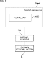
- Fig. 1 is a block diagram illustrating a control apparatus 2000 according to Example 1 along with a usage environment thereof.
- a charging apparatus 20 is an apparatus that performs charging of a lithium ion secondary battery 10.
- the control apparatus 2000 includes a control unit 2020.
- the control unit 2020 causes the charging apparatus 20 to charge the lithium ion secondary battery 10, by controlling the charging apparatus 20. At that time, the control unit 2020 controls the charging apparatus 20 as described below.
- the control unit 2020 causes the charging apparatus 20 to charge the lithium ion secondary battery 10, until a voltage of the lithium ion secondary battery 10 becomes a predetermined voltage. Thereafter, the control unit 2020 causes the charging apparatus 20 to suspend the charging of the lithium ion secondary battery 10, until a predetermined time elapses. The control unit 2020 causes the charging apparatus 20 to further perform the charging of the lithium ion secondary battery 10, after the suspension.
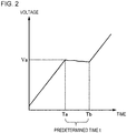
- Fig. 2 is a diagram illustrating a transition of the voltage, regarding the lithium ion secondary battery 10 charged by the charging apparatus 20 that is controlled by the control apparatus 2000.
- a voltage Va is the predetermined voltage described above.
- the control unit 2020 causes the charging apparatus 20 to perform the charging of the lithium ion secondary battery 10, until the voltage of the lithium ion secondary battery 10 becomes Va. As a result, the voltage of the lithium ion secondary battery 10 becomes Va at a time point Ta.
- control unit 2020 causes the charging of the lithium ion secondary battery 10 to be suspended, until a predetermined suspension time t elapses.
- suspension time the time during which the charging of the lithium ion secondary battery 10 is suspended.
- the control unit 2020 causes the charging apparatus 20 to further perform the charging of the lithium ion secondary battery 10, from a time point Tb.
- the time point Tb is a point of time at which the suspension time t elapses from the time point Ta.
- the suspension time t satisfies a condition of Expression (3) below.
- Expression 3 t ⁇ ⁇ A + B ⁇ x + C ⁇ y 50 ⁇ A ⁇ 70,500 ⁇ B ⁇ 620,30 ⁇ C ⁇ 36 x represents weight per unit area of a negative electrode of the lithium ion secondary battery 10.
- the unit thereof is g/cm 2 .
- y is density of the negative electrode.
- the unit thereof is g/cm 3 .
- the unit of t is minute.
- A, B, and C are respectively constants.
- the suspension time t may be set as 0.
- the control apparatus 2000 may cause the charging of the lithium ion secondary battery 10 not to be suspended.
- the present inventors found out that lithium deposits on a surface of the negative electrode of the lithium ion secondary battery 10 during the charging of the lithium ion secondary battery 10. For example, a cause of this phenomenon is considered as follows.
- Figs. 3 are diagram illustrating a state of the negative electrode of the lithium ion secondary battery 10 at the time of charging the lithium ion secondary battery 10.
- Fig. 3A illustrates the state of the negative electrode of the lithium ion secondary battery 10 before a start of the charging.
- the negative electrode of the lithium ion secondary battery 10 is configured by combining an active material 50 with a current collector 60.
- a main component of the active material 50 is graphite.
- Fig. 3B illustrates the state of the negative electrode of the lithium ion secondary battery 10 after the start of the charging.
- Fig. 3C illustrates the state in which lithium deposits on the surface of the active material 50.
- the control apparatus 2000 of the present invention suspends the charging for a predetermined time.
- the lithium ions which are incorporated into the active material 50 are unevenly distributed in the active material 50, as the lithium ion secondary battery 10 is charged up to the predetermined voltage ( Fig. 3B ).
- the lithium ions are dispersed in the active material 50 in the meanwhile. Accordingly, even if the charging of the lithium ion secondary battery 10 is further performed after the suspension, the deposition of lithium due to the unevenness of the distribution of the lithium ions is less likely to be caused.
- control apparatus 2000 of the present invention it is possible to charge the lithium ion secondary battery 10, while preventing the deposition of lithium from the negative electrode of the lithium ion secondary battery 10.
- control apparatus 2000 of the present invention it is possible to prevent the deposition of lithium on the negative electrode, without lowering the density of the negative electrode. Accordingly, it is possible to raise the volume energy density of the lithium ion secondary battery 10.
- Each functional configuration unit of the control apparatus 2000 may be realized by hardware (example: hard-wired electronic circuit or the like) that realizes each functional configuration unit, or may be realized by a combination (example: combination of an electronic circuit with a program for controlling the same, or the like) of hardware with software.
- hardware example: hard-wired electronic circuit or the like
- combination example: combination of an electronic circuit with a program for controlling the same, or the like
- each functional configuration unit of the control apparatus 2000 is realized by the combination of the hardware with the software will be further described.
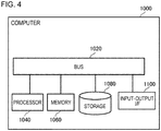
- Fig. 4 is a diagram illustrating a computer 1000 for realizing the control apparatus 2000.
- the computer 1000 is any computer.
- the computer 1000 is a micro control unit (MCU), a personal computer (PC), a server machine, or the like.
- the computer 1000 may be an exclusive-use computer that is designed in order to realize the control apparatus 2000, or may be a general-purpose computer.
- the computer 1000 includes a bus 1020, a processor 1040, a memory 1060, a storage device 1080, and an input-output interface 1100.
- the bus 1020 is a data transmission channel for sending and receiving data to each other in the processor 1040, the memory 1060, the storage device 1080, and the input-output interface 1100.
- a method of connecting the processors 1040 and the like to each other is not limited to the bus connection.
- the processor 1040 is an arithmetic processing apparatus such as a microprocessor or a central processing unit (CPU).
- the memory 1060 is a memory such as a random access memory (RAM).
- the storage device 1080 is a storing apparatus such as a read only memory (ROM), a flash memory, or a hard disk.
- the input-output interface 1100 is an interface for connecting the computer 1000 to an input-output device.
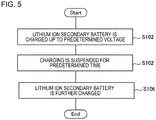
- Fig. 5 is a flowchart illustrating a flow of processing that is executed by the control apparatus 2000 according to Example 1.
- the control unit 2020 controls the charging apparatus 20, and causes the lithium ion secondary battery 10 to be charged up to the predetermined voltage (S102).
- the control unit 2020 controls the charging apparatus 20, and causes the charging of the lithium ion secondary battery 10 to be suspended for the predetermined time (S104). After S104, the control unit 2020 controls the charging apparatus 20, and causes the lithium ion secondary battery 10 to be further charged (S106).
- Fig. 6 is a diagram further specifically illustrating a usage environment of the control apparatus 2000.
- the lithium ion secondary battery 10 is configured as an assembled battery in which a plurality of unit battery cells 12 are connected in series.
- the charging apparatus 20 is connected to the lithium ion secondary battery 10.
- the lithium ion secondary battery 10 is included in a battery pack 30. Furthermore, the battery pack 30 includes a voltage measuring machine 40 that measures the voltage of the lithium ion secondary battery 10.
- the control apparatus 2000 is connected to the voltage measuring machine 40 which is included in the battery pack 30.
- the control apparatus 2000 repeatedly obtains the voltage of the lithium ion secondary battery 10, from the voltage measuring machine 40. By doing so, it is recognized that the voltage of the lithium ion secondary battery 10 becomes the predetermined voltage by the control apparatus 2000. Furthermore, the control apparatus 2000 is connected to the charging apparatus 20.
- control apparatus 2000 is not limited to an example illustrated in Fig. 5 .
- control apparatus 2000 may be provided on the inside of the charging apparatus 20.
- the lithium ion secondary battery 10 is necessarily configured as an assembled battery.
- the components of a positive electrode terminal and a negative electrode terminal of the lithium ion secondary battery 10 are optional.
- the positive electrode terminal of the lithium ion secondary battery 10 is a terminal using a nickel-based positive electrode material as an active material.
- the negative electrode terminal of the lithium ion secondary battery 10 is a terminal using a material whose main component is graphite as an active material.
- the suspension time t representing a length of the suspension time is represented by Expression (3).
- a method for introducing a range of each parameter A to C in Expression (3) will be described.
- the range of a value of each parameter described above is introduced by a test described below.
- the battery cells of a plurality of patterns whose the weight per unit area of the negative electrode and the density of the negative electrode are different from each other are used.
- CCCV charging constant current and constant voltage charging
- the charging is suspended for the predetermined time, in each of a time point at which the charging voltage is 4.0 V and a time point at which the charging voltage is 4.1 V.
- the test is performed onto each of cases where the suspension time are 1 minute, 3 minutes, and 5 minutes. The test is performed onto a case where the suspension is not performed as well.
- the cell after the charging is discharged (0.2 C, 2.5 V)
- the cell is disassembled, and the surface of the negative electrode is visually observed.
- deposition with white color is perceived on the surface of the negative electrode
- it is determined that lithium had deposited it is determined that lithium had not deposited (the lithium deposition is prevented).
- Table 1 to Table 3 hereinafter are tables illustrating test results.
- [Table 1] Suspension time/density of negative electrode 1.55 1.5 1.46 1.4 0 x ⁇ 1 x ⁇ 3 x ⁇ 5 ⁇ 10
- Table 1 illustrates a test result of a case where the weight per unit area of the negative electrode is 0.024 g/cm.
- Table 2 Suspension time/density of negative electrode 1.55 1.5 1.46 1.4 0 x ⁇ ⁇ 1 x ⁇ 3 ⁇ 5 10
- Table 2 illustrates a test result of a case where the weight per unit area of the negative electrode is 0.021 g/cm.
- [Table 3] Suspension time/density of negative electrode 1.55 1.5 1.46 1.4 0 x ⁇ ⁇ ⁇ 1 ⁇ 3 5 10
- Table 3 illustrates a test result of a case where the weight per unit area of the negative electrode is 0.018 g/cm 2 .
- lithium is likely to deposit on the negative electrode as the weight per unit area of the negative electrode is large, and lithium is likely to deposit on the negative electrode as the density of the negative electrode is high.
- an upper limit value of the range of A, an upper limit value of the range of B , and an upper limit value of the range of C are 65, 590, and 34, respectively.
- a lower limit value of the range of A, a lower limit value of the range of B, and a lower limit value of the range of C are 55, 530, and 32, respectively.
- the control unit 2020 causes the charging apparatus 20 to perform the charging of the lithium ion secondary battery 10, until the voltage of the lithium ion secondary battery 10 becomes the predetermined voltage (S102).
- the predetermined voltage is a voltage with which a state of charge (SOC) of the lithium ion secondary battery 10 is equal to or more than 70% and equal to or less than 100% in a case where the lithium ion secondary battery 10 is charged at the charging rate of 0.2 C.
- the lower limit value of the range of the predetermined voltage is 75% of the SOC of the lithium ion secondary battery 10 by the charging described above.
- the further suitable lower limit value is 80% of the SOC of the lithium ion secondary battery 10 by the same charging.
- the upper limit value of the range of the predetermined voltage is 95% of the SOC of the lithium ion secondary battery 10 by the same charging.
- the further suitable upper limit value is 90% of the SOC of the lithium ion secondary battery 10 by the same charging.
- the suspension time t that is the time during which the charging of the lithium ion secondary battery 10 is suspended is computed in advance before the suspension of the charging of the lithium ion secondary battery 10 is started.
- the control apparatus 2000 receives inputs of the weight per unit area x of the negative electrode of the lithium ion secondary battery 10 and the density y of the negative electrode from the user.
- the user inputs the value described above, using any input device (for example, a keyboard).
- the control apparatus 2000 computes the input value by the computation expression on the right side of Expression (3), and sets a computation result thereof as suspension time t.
- the range of each parameter of Expression (3) is set in advance to one value which is included in the range described above.
- the computed suspension time t is stored in the storing apparatus (for example, the storage device 1080 of Fig. 4 ) which is accessible from the control unit 2020.
- control apparatus 2000 may set a value that is larger than the value which is obtained on the right side of Expression (3) as suspension time t.
- control apparatus 2000 sets a value obtained by adding a predetermined value to the obtained value as suspension time t.
- the predetermined value thereof may be specified by a user, may be set in advance in the control apparatus 2000, or may be stored in the storing apparatus which is accessible from the control apparatus 2000.
- the control unit 2020 may cause the charging apparatus 20 to perform suspensions of the charging a plurality of times. At this time, timing of performing a first suspension is timing at which the voltage of the lithium ion secondary battery 10 becomes equal to or more than the predetermined voltage. A second suspension and subsequent suspensions may be started any timing. The lengths of the second suspension and subsequent suspensions may be any length.
- the control apparatus 2000 of the example is represented by, for example, Fig. 1 , in the same manner as the control apparatus 2000 of Example 1. Except for points described below, the control apparatus 2000 of Example 2 has functions which are the same as those of the control apparatus 2000 of Example 1.
- the predetermined suspension time t during which the charging of the lithium ion secondary battery 10 is suspended is set as "length that is equal to or more than time from a time point at which the voltage of the lithium ion secondary battery 10 becomes the predetermined voltage described above to a time point at which a temporal change ratio of the voltage of the lithium ion secondary battery 10 becomes a local minimum value". To do so, test measurement for determining the suspension time t is performed, in advance before the control apparatus 2000 is used.
- the suspension time t is determined as follows. First, after the lithium ion secondary battery 10 is charged up to the predetermined voltage described above, a temporal change of the voltage of the lithium ion secondary battery 10 is measured. Furthermore, from a measurement result thereof, a time point at which the temporal change ratio of the voltage of the lithium ion secondary battery 10 becomes the local minimum value is computed. Therefore, the value of the suspension time t is set to a value which is equal to or more than the computed time.
- Figs. 7 are diagrams illustrating a transition of an OCV of the lithium ion secondary battery 10.
- CC charging constant current charging
- Fig. 7B represents the temporal change ratio (graph obtained by differentiating a graph of Fig. 7A ) of the OCV
- the time point T1 is a time point at which a shoulder is viewed in the graph of Fig. 7A .
- the time point T1 is a time point at which the graph of Fig. 7B becomes the local minimum value.
- the change in the OCV of the lithium ion secondary battery 10 illustrates that the distribution of the lithium ions in the lithium ion secondary battery 10 is changed.
- the change in the distribution of the lithium ions is derived from any of the negative electrode, the positive electrode, and the electrolytic solution.
- the shoulder which is viewed at the time point T1 in Fig. 7 illustrates that the distribution of the lithium ions in the negative electrode is made substantially even, and it is considered that the lithium deposition is prevented, by providing the suspension of time which is equal to or more than the time point T1. Note that, the change in the OCV after T1 is considered to be derived from the positive electrode side.
- the control apparatus 2000 of the present example sets a termination time point of the suspension of the lithium ion secondary battery 10 as a time point after the time point at which the temporal change ratio of the voltage of the lithium ion secondary battery 10 becomes the local minimum value, after the suspension of the charging of the lithium ion secondary battery 10 is started. By doing so, the deposition of lithium on the negative electrode of the lithium ion secondary battery 10 is prevented.
- the suspension time t it is also considered that a plurality of time points at which the temporal change ratio of the voltage of the lithium ion secondary battery 10 becomes the local minimum value are present.
- the suspension time t it is possible to set the suspension time t to be after any time point in the plurality of time points.
- the suspension time is set as the smallest time point in the plurality of time points, or a time point after the smallest time point.
- the control apparatus 2000 of Example 2 is realized using the computer 1000 in the same manner as Example 1 (see Fig. 4 ).
- control apparatus 2000 of the present embodiment an advantageous effect which is the same as that of the control apparatus 2000 of Example 1 is obtained.
- the control apparatus 2000 it is possible to manually carry out a portion or all of the processing which is executed by the control apparatus 2000 in each example. In this case, it is made such that the start and the stop of the charging in the charging apparatus 20 are manually operable. Moreover, it is made such that a person can recognize that the voltage of the lithium ion secondary battery 10 becomes equal to or more than the predetermined voltage. For example, it is made such that the voltage of the lithium ion secondary battery 10 which is measured by a voltage measuring circuit is displayed on a display apparatus or the like. Hereinafter, the person who operates the charging apparatus 20 is referred to as an operator.
- the operator operates the charging apparatus 20, and causes the charging apparatus 20 to charge the lithium ion secondary battery 10.
- the operator monitors the voltage of the lithium ion secondary battery 10 which is displayed on the display apparatus.
- the operator operates the charging apparatus 20, and causes the charging of the lithium ion secondary battery 10 to be suspended.
- the operator operates the charging apparatus 20, and causes the charging of the lithium ion secondary battery 10 to be restarted.
Landscapes
- Engineering & Computer Science (AREA)
- Manufacturing & Machinery (AREA)
- Chemical & Material Sciences (AREA)
- Chemical Kinetics & Catalysis (AREA)
- Electrochemistry (AREA)
- General Chemical & Material Sciences (AREA)
- Power Engineering (AREA)
- Charge And Discharge Circuits For Batteries Or The Like (AREA)
- Secondary Cells (AREA)
Claims (6)
- System, das Folgendes umfasst:eine Lithiumionensekundärbatterie (10), die ein Gewicht pro Flächeneinheit x [g/cm2] einer negativen Elektrode der Lithiumionensekundärbatterie (10) und eine Dichte y [g/cm3] der negativen Elektrode aufweist, undeine Steuervorrichtung (2000), die umfasst:
eine Steuereinheit (2020), die zum Steuern einer Ladevorrichtung (20) konfiguriert ist, die zum Ausführen von Ladung der Lithiumionensekundärbatterie (10) konfiguriert ist, wobei die Steuereinheit (2020) konfiguriert ist auszuführen:Veranlassen der Ladevorrichtung (20) zum Ausführen der Ladung der Lithiumionensekundärbatterie (10) bis eine Spannung der Lithiumionensekundärbatterie (10) eine vorgegebene Spannung wird;Veranlassen der Ladevorrichtung (20) zum Aussetzen der Ladung der Lithiumionensekundärbatterie (10), bis eine vorgegebene Zeit t vergeht, nach der Ladung; undVeranlassen der Ladevorrichtung (20), die Ladung der Lithiumionensekundärbatterie (10), nach dem Aussetzen, weiter auszuführen, unddadurch gekennzeichnet, dass die Steuervorrichtung (2000) konfiguriert ist, die vorgegebene Zeit t [Minute] festzusetzen, indem sie konfiguriert ist, die vorgegebene Zeit t [Minute] so zu berechnen, dass sie eine Bedingung erfüllt,die durch Ausdruck (1) unter Verwendung des Gewichts pro Flächeneinheit x [g/cm2] der negativen Elektrode der Lithiumionensekundärbatterie (10) und der Dichte y [g/cm3] der negativen Elektrode bestimmt ist,wobei Ausdruck 1 ist: wobei die Einheit von Koeffizient A [Minute] ist, die Einheit von Koeffizient B [Minute/(g/cm2)] ist und die Einheit von Koeffizient C [Minute/(g/cm3)] ist.
 - System gemäß Anspruch 1, wobei die vorgegebene Spannung eine Spannung ist, bei der ein Ladezustand der Lithiumionensekundärbatterie (10) gleich oder mehr als 70 % und gleich oder weniger als 100 % ist in einem Fall, wenn die Lithiumionensekundärbatterie (10) konfiguriert ist, bei einer Laderate von 0,2 C geladen zu werden.
- Steuerungsverfahren, das Folgendes umfasst:einen Schritt des Veranlassens einer Ladevorrichtung (20), die eine Ladung einer Lithiumionensekundärbatterie (10) ausführt, die Ladung der Lithiumionensekundärbatterie (10) auszuführen, bis eine Spannung der Lithiumionensekundärbatterie (10) eine vorgegebene Spannung wird;einen Schritt des Veranlassens der Ladevorrichtung (20), die Ladung der Lithiumionensekundärbatterie (10) auszusetzen, bis eine vorgegebene Zeit t vergeht, nach der Ladung; undeinen Schritt des Veranlassens der Ladevorrichtung (20) zum weiteren Ausführen der Ladung der Lithiumionensekundärbatterie (10), nach dem Aussetzen,dadurch gekennzeichnet, dass die vorgegebene Zeit t [Minute] festgesetzt wird, indem die vorgegebene Zeit t [Minute] so berechnet wird, dass sie eine Bedingung erfüllt, die durch Ausdruck (2) unter Verwendung eines Gewichts pro Flächeneinheit x [g/cm2] einer negativen Elektrode der Lithiumionensekundärbatterie (10) und einer Dichte y [g/cm3] der negativen Elektrode bestimmt wird,wobei Ausdruck 2 ist:
 wobei die Einheit von Koeffizient A [Minute] ist, die Einheit von Koeffizient B [Minute/(g/cm2)] ist und die Einheit von Koeffizient C [Minute/(g/cm3)] ist.
 - Steuerungsverfahren, das Folgendes umfasst:einen Schritt des Veranlassens einer Ladevorrichtung (20), die eine Ladung einer Lithiumionensekundärbatterie (10) ausführt, die Ladung der Lithiumionensekundärbatterie (10) auszuführen, bis eine Spannung der Lithiumionensekundärbatterie (10) eine vorgegebene Spannung wird;einen Schritt des Veranlassens der Ladevorrichtung (20), die Ladung der Lithiumionensekundärbatterie (10) auszusetzen, bis eine vorgegebene Zeit t vergeht, nach der Ladung; undeinen Schritt des Veranlassens der Ladevorrichtung (20) zum weiteren Ausführen der Ladung der Lithiumionensekundärbatterie (10), nach dem Aussetzen,dadurch gekennzeichnet, dass die vorgegebene Zeit t [Minute] eine Länge ist, die gleich einer oder mehr als eine Zeit von einem Zeitpunkt, an dem das Aussetzen begonnen wird, zu einem Zeitpunkt, an dem ein zeitliches Änderungsverhältnis einer Leerlaufspannung der Lithiumionensekundärbatterie (10) ein lokaler Minimalwert wird, wobei die Spannung der Lithiumionensekundärbatterie (10) durch eine Spannungsmesseinheit (40) bestimmt wird.
- Steuerungsverfahren gemäß Anspruch 3 oder 4, wobei die vorgegebene Spannung eine Spannung ist, bei der ein Ladezustand der Lithiumionensekundärbatterie (10) gleich oder mehr als 70 % und gleich oder weniger als 100 % in einem Fall ist, wenn die Lithiumionensekundärbatterie (10) bei einer Laderate von 0,2 C geladen wird.
- Programm, das einen Computer zum Ausführen jedes Schritts des Steuerungsverfahrens gemäß einem der Ansprüche 3 bis 5 veranlasst.
Applications Claiming Priority (2)
| Application Number | Priority Date | Filing Date | Title |
|---|---|---|---|
| JP2016219447 | 2016-11-10 | ||
| PCT/JP2017/039105 WO2018088260A1 (ja) | 2016-11-10 | 2017-10-30 | 制御装置、制御方法、及びプログラム |
Publications (3)
| Publication Number | Publication Date |
|---|---|
| EP3540907A1 EP3540907A1 (de) | 2019-09-18 |
| EP3540907A4 EP3540907A4 (de) | 2020-04-01 |
| EP3540907B1 true EP3540907B1 (de) | 2021-05-19 |
Family
ID=62109151
Family Applications (1)
| Application Number | Title | Priority Date | Filing Date |
|---|---|---|---|
| EP17869307.3A Active EP3540907B1 (de) | 2016-11-10 | 2017-10-30 | Steuerungsvorrichtung, steuerungsverfahren und programm |
Country Status (5)
| Country | Link |
|---|---|
| US (1) | US11245137B2 (de) |
| EP (1) | EP3540907B1 (de) |
| JP (1) | JP6895452B2 (de) |
| CN (1) | CN110024257B (de) |
| WO (1) | WO2018088260A1 (de) |
Families Citing this family (2)
| Publication number | Priority date | Publication date | Assignee | Title |
|---|---|---|---|---|
| CN110024257B (zh) * | 2016-11-10 | 2022-11-25 | 远景Aesc日本有限公司 | 控制装置、控制方法和计算机可读存储介质 |
| KR20230111506A (ko) * | 2022-01-18 | 2023-07-25 | 주식회사 엘지에너지솔루션 | 배터리 제어 장치 및 방법 |
Family Cites Families (10)
| Publication number | Priority date | Publication date | Assignee | Title |
|---|---|---|---|---|
| JP2005071697A (ja) | 2003-08-21 | 2005-03-17 | Toshiba Corp | 非水電解質二次電池の初充電方法 |
| WO2009090913A1 (ja) * | 2008-01-14 | 2009-07-23 | Toyota Jidosha Kabushiki Kaisha | リチウムイオン二次電池の充電方法、及び、ハイブリッド自動車 |
| JP2012016109A (ja) * | 2010-06-30 | 2012-01-19 | Panasonic Corp | リチウムイオン電池の充電方法および充電装置 |
| JP2012055086A (ja) * | 2010-09-01 | 2012-03-15 | Hitachi Maxell Energy Ltd | 充電ユニット及びそれを備えた電気機器 |
| JP2012247339A (ja) * | 2011-05-30 | 2012-12-13 | Renesas Electronics Corp | 半導体集積回路およびその動作方法 |
| CN104854772B (zh) * | 2012-12-14 | 2017-05-10 | 日立麦克赛尔株式会社 | 蓄电装置及其充电方法 |
| JP2015104139A (ja) | 2013-11-20 | 2015-06-04 | 株式会社Wave Technology | 二次電池の充電方法およびそれを用いた充電装置 |
| JP2015154593A (ja) * | 2014-02-14 | 2015-08-24 | ソニー株式会社 | 充放電制御装置、電池パック、電子機器、電動車両および充放電制御方法 |
| JP6625345B2 (ja) | 2015-05-14 | 2019-12-25 | 日置電機株式会社 | 電気二重層キャパシタの電圧保持率特定装置および電気二重層キャパシタの電圧保持率特定方法 |
| CN110024257B (zh) * | 2016-11-10 | 2022-11-25 | 远景Aesc日本有限公司 | 控制装置、控制方法和计算机可读存储介质 |
-
2017
- 2017-10-30 CN CN201780069379.3A patent/CN110024257B/zh active Active
- 2017-10-30 WO PCT/JP2017/039105 patent/WO2018088260A1/ja not_active Ceased
- 2017-10-30 EP EP17869307.3A patent/EP3540907B1/de active Active
- 2017-10-30 US US16/347,879 patent/US11245137B2/en active Active
- 2017-10-30 JP JP2018550146A patent/JP6895452B2/ja active Active
Non-Patent Citations (1)
| Title |
|---|
| None * |
Also Published As
| Publication number | Publication date |
|---|---|
| JPWO2018088260A1 (ja) | 2019-09-26 |
| US20190312316A1 (en) | 2019-10-10 |
| CN110024257A (zh) | 2019-07-16 |
| EP3540907A1 (de) | 2019-09-18 |
| US11245137B2 (en) | 2022-02-08 |
| CN110024257B (zh) | 2022-11-25 |
| WO2018088260A1 (ja) | 2018-05-17 |
| EP3540907A4 (de) | 2020-04-01 |
| JP6895452B2 (ja) | 2021-06-30 |
Similar Documents
| Publication | Publication Date | Title |
|---|---|---|
| EP3226016B1 (de) | Nachweismethode der li-beschichtung, verfahren und vorrichtung zum laden einer sekundärbatterie und sekundärbatteriesystem, das diese verwendet | |
| CN109586373B (zh) | 一种电池充电方法和装置 | |
| US10135279B2 (en) | Method and apparatus of battery charging | |
| EP4099039B1 (de) | Verfahren zur bestimmung der alterung einer batterie, vorrichtung zur bestimmung der alterung einer batterie, verwaltungssystem für batterien, batteriemontierte vorrichtung und programm zur bestimmung der alterung einer batterie | |
| JP6656383B2 (ja) | バッテリーセルの性能テスト装置及び方法 | |
| CN110940920B (zh) | 锂电池在预定soc下的不析锂的最大充电电流的获取方法 | |
| WO2014036527A1 (en) | Method and apparatus for charging a battery with globally minimized integral degradation for predefined charging duration | |
| CA3027233A1 (en) | Method and device for estimating a voltage of a battery | |
| CN114069077B (zh) | 电化学装置管理方法、电子设备及电池系统 | |
| CN106154175B (zh) | 基于动态压差的充电电池荷电状态估算系统及工作流程 | |
| KR102862040B1 (ko) | 배터리 제어 방법 및 장치 | |
| JP2023530297A (ja) | バッテリー管理装置及び方法 | |
| US20220069361A1 (en) | Control of Lithium Plating of Lithium-Ion Battery During Charging | |
| EP4332594B1 (de) | Verfahren und vorrichtung zur bestimmung des ladezustandes eines batteriesystems | |
| CN110795855A (zh) | 检测锂镀覆电势的方法、存储介质以及系统 | |
| EP3540907B1 (de) | Steuerungsvorrichtung, steuerungsverfahren und programm | |
| Liu et al. | Research on safe charging strategy of lithium-ion battery based on three-electrode equivalent circuit model | |
| CN114397582A (zh) | 析锂检测方法、电子设备、充电装置及存储介质 | |
| EP4468557A1 (de) | Verfahren zur herstellung eines ladeprotokolls für lithiumsekundärbatterie, batterieverwaltungssystem, batteriepack und batteriezellenladevorrichtung | |
| CN110178284A (zh) | 控制放电的设备和方法 | |
| WO2023133696A1 (zh) | 电化学装置管理方法、充电装置、电池系统及电子设备 | |
| CN120222570A (zh) | 电池充电倍率的确定方法、装置、电子设备及存储介质 | |
| CN118281382A (zh) | 电化学装置管理方法及其设备、电化学装置及用电设备 | |
| CN119881701B (zh) | 电池包剩余电量检测方法及系统 | |
| CN119069852B (zh) | 锂离子电池的化成控制方法以及化成系统 |
Legal Events
| Date | Code | Title | Description |
|---|---|---|---|
| STAA | Information on the status of an ep patent application or granted ep patent |
Free format text: STATUS: THE INTERNATIONAL PUBLICATION HAS BEEN MADE |
|
| PUAI | Public reference made under article 153(3) epc to a published international application that has entered the european phase |
Free format text: ORIGINAL CODE: 0009012 |
|
| STAA | Information on the status of an ep patent application or granted ep patent |
Free format text: STATUS: REQUEST FOR EXAMINATION WAS MADE |
|
| 17P | Request for examination filed |
Effective date: 20190502 |
|
| AK | Designated contracting states |
Kind code of ref document: A1 Designated state(s): AL AT BE BG CH CY CZ DE DK EE ES FI FR GB GR HR HU IE IS IT LI LT LU LV MC MK MT NL NO PL PT RO RS SE SI SK SM TR |
|
| AX | Request for extension of the european patent |
Extension state: BA ME |
|
| DAV | Request for validation of the european patent (deleted) | ||
| DAX | Request for extension of the european patent (deleted) | ||
| RIN1 | Information on inventor provided before grant (corrected) |
Inventor name: SASAKI, HIDEAKI |
|
| A4 | Supplementary search report drawn up and despatched |
Effective date: 20200228 |
|
| RIC1 | Information provided on ipc code assigned before grant |
Ipc: H01M 10/44 20060101ALI20200224BHEP Ipc: H02J 7/00 20060101ALI20200224BHEP Ipc: H02J 7/10 20060101AFI20200224BHEP Ipc: H01M 10/48 20060101ALI20200224BHEP |
|
| GRAP | Despatch of communication of intention to grant a patent |
Free format text: ORIGINAL CODE: EPIDOSNIGR1 |
|
| STAA | Information on the status of an ep patent application or granted ep patent |
Free format text: STATUS: GRANT OF PATENT IS INTENDED |
|
| INTG | Intention to grant announced |
Effective date: 20210115 |
|
| GRAS | Grant fee paid |
Free format text: ORIGINAL CODE: EPIDOSNIGR3 |
|
| GRAA | (expected) grant |
Free format text: ORIGINAL CODE: 0009210 |
|
| STAA | Information on the status of an ep patent application or granted ep patent |
Free format text: STATUS: THE PATENT HAS BEEN GRANTED |
|
| AK | Designated contracting states |
Kind code of ref document: B1 Designated state(s): AL AT BE BG CH CY CZ DE DK EE ES FI FR GB GR HR HU IE IS IT LI LT LU LV MC MK MT NL NO PL PT RO RS SE SI SK SM TR |
|
| REG | Reference to a national code |
Ref country code: GB Ref legal event code: FG4D |
|
| REG | Reference to a national code |
Ref country code: CH Ref legal event code: EP |
|
| REG | Reference to a national code |
Ref country code: DE Ref legal event code: R096 Ref document number: 602017039015 Country of ref document: DE |
|
| REG | Reference to a national code |
Ref country code: AT Ref legal event code: REF Ref document number: 1394936 Country of ref document: AT Kind code of ref document: T Effective date: 20210615 |
|
| REG | Reference to a national code |
Ref country code: IE Ref legal event code: FG4D |
|
| REG | Reference to a national code |
Ref country code: LT Ref legal event code: MG9D |
|
| REG | Reference to a national code |
Ref country code: AT Ref legal event code: MK05 Ref document number: 1394936 Country of ref document: AT Kind code of ref document: T Effective date: 20210519 |
|
| REG | Reference to a national code |
Ref country code: NL Ref legal event code: MP Effective date: 20210519 |
|
| PG25 | Lapsed in a contracting state [announced via postgrant information from national office to epo] |
Ref country code: HR Free format text: LAPSE BECAUSE OF FAILURE TO SUBMIT A TRANSLATION OF THE DESCRIPTION OR TO PAY THE FEE WITHIN THE PRESCRIBED TIME-LIMIT Effective date: 20210519 Ref country code: BG Free format text: LAPSE BECAUSE OF FAILURE TO SUBMIT A TRANSLATION OF THE DESCRIPTION OR TO PAY THE FEE WITHIN THE PRESCRIBED TIME-LIMIT Effective date: 20210819 Ref country code: AT Free format text: LAPSE BECAUSE OF FAILURE TO SUBMIT A TRANSLATION OF THE DESCRIPTION OR TO PAY THE FEE WITHIN THE PRESCRIBED TIME-LIMIT Effective date: 20210519 Ref country code: LT Free format text: LAPSE BECAUSE OF FAILURE TO SUBMIT A TRANSLATION OF THE DESCRIPTION OR TO PAY THE FEE WITHIN THE PRESCRIBED TIME-LIMIT Effective date: 20210519 Ref country code: FI Free format text: LAPSE BECAUSE OF FAILURE TO SUBMIT A TRANSLATION OF THE DESCRIPTION OR TO PAY THE FEE WITHIN THE PRESCRIBED TIME-LIMIT Effective date: 20210519 |
|
| PG25 | Lapsed in a contracting state [announced via postgrant information from national office to epo] |
Ref country code: SE Free format text: LAPSE BECAUSE OF FAILURE TO SUBMIT A TRANSLATION OF THE DESCRIPTION OR TO PAY THE FEE WITHIN THE PRESCRIBED TIME-LIMIT Effective date: 20210519 Ref country code: RS Free format text: LAPSE BECAUSE OF FAILURE TO SUBMIT A TRANSLATION OF THE DESCRIPTION OR TO PAY THE FEE WITHIN THE PRESCRIBED TIME-LIMIT Effective date: 20210519 Ref country code: LV Free format text: LAPSE BECAUSE OF FAILURE TO SUBMIT A TRANSLATION OF THE DESCRIPTION OR TO PAY THE FEE WITHIN THE PRESCRIBED TIME-LIMIT Effective date: 20210519 Ref country code: PT Free format text: LAPSE BECAUSE OF FAILURE TO SUBMIT A TRANSLATION OF THE DESCRIPTION OR TO PAY THE FEE WITHIN THE PRESCRIBED TIME-LIMIT Effective date: 20210920 Ref country code: PL Free format text: LAPSE BECAUSE OF FAILURE TO SUBMIT A TRANSLATION OF THE DESCRIPTION OR TO PAY THE FEE WITHIN THE PRESCRIBED TIME-LIMIT Effective date: 20210519 Ref country code: NO Free format text: LAPSE BECAUSE OF FAILURE TO SUBMIT A TRANSLATION OF THE DESCRIPTION OR TO PAY THE FEE WITHIN THE PRESCRIBED TIME-LIMIT Effective date: 20210819 Ref country code: GR Free format text: LAPSE BECAUSE OF FAILURE TO SUBMIT A TRANSLATION OF THE DESCRIPTION OR TO PAY THE FEE WITHIN THE PRESCRIBED TIME-LIMIT Effective date: 20210820 Ref country code: IS Free format text: LAPSE BECAUSE OF FAILURE TO SUBMIT A TRANSLATION OF THE DESCRIPTION OR TO PAY THE FEE WITHIN THE PRESCRIBED TIME-LIMIT Effective date: 20210919 |
|
| PG25 | Lapsed in a contracting state [announced via postgrant information from national office to epo] |
Ref country code: NL Free format text: LAPSE BECAUSE OF FAILURE TO SUBMIT A TRANSLATION OF THE DESCRIPTION OR TO PAY THE FEE WITHIN THE PRESCRIBED TIME-LIMIT Effective date: 20210519 |
|
| PG25 | Lapsed in a contracting state [announced via postgrant information from national office to epo] |
Ref country code: SK Free format text: LAPSE BECAUSE OF FAILURE TO SUBMIT A TRANSLATION OF THE DESCRIPTION OR TO PAY THE FEE WITHIN THE PRESCRIBED TIME-LIMIT Effective date: 20210519 Ref country code: SM Free format text: LAPSE BECAUSE OF FAILURE TO SUBMIT A TRANSLATION OF THE DESCRIPTION OR TO PAY THE FEE WITHIN THE PRESCRIBED TIME-LIMIT Effective date: 20210519 Ref country code: ES Free format text: LAPSE BECAUSE OF FAILURE TO SUBMIT A TRANSLATION OF THE DESCRIPTION OR TO PAY THE FEE WITHIN THE PRESCRIBED TIME-LIMIT Effective date: 20210519 Ref country code: EE Free format text: LAPSE BECAUSE OF FAILURE TO SUBMIT A TRANSLATION OF THE DESCRIPTION OR TO PAY THE FEE WITHIN THE PRESCRIBED TIME-LIMIT Effective date: 20210519 Ref country code: CZ Free format text: LAPSE BECAUSE OF FAILURE TO SUBMIT A TRANSLATION OF THE DESCRIPTION OR TO PAY THE FEE WITHIN THE PRESCRIBED TIME-LIMIT Effective date: 20210519 Ref country code: DK Free format text: LAPSE BECAUSE OF FAILURE TO SUBMIT A TRANSLATION OF THE DESCRIPTION OR TO PAY THE FEE WITHIN THE PRESCRIBED TIME-LIMIT Effective date: 20210519 Ref country code: RO Free format text: LAPSE BECAUSE OF FAILURE TO SUBMIT A TRANSLATION OF THE DESCRIPTION OR TO PAY THE FEE WITHIN THE PRESCRIBED TIME-LIMIT Effective date: 20210519 |
|
| REG | Reference to a national code |
Ref country code: DE Ref legal event code: R097 Ref document number: 602017039015 Country of ref document: DE |
|
| PLBE | No opposition filed within time limit |
Free format text: ORIGINAL CODE: 0009261 |
|
| STAA | Information on the status of an ep patent application or granted ep patent |
Free format text: STATUS: NO OPPOSITION FILED WITHIN TIME LIMIT |
|
| 26N | No opposition filed |
Effective date: 20220222 |
|
| REG | Reference to a national code |
Ref country code: CH Ref legal event code: PL |
|
| PG25 | Lapsed in a contracting state [announced via postgrant information from national office to epo] |
Ref country code: IS Free format text: LAPSE BECAUSE OF FAILURE TO SUBMIT A TRANSLATION OF THE DESCRIPTION OR TO PAY THE FEE WITHIN THE PRESCRIBED TIME-LIMIT Effective date: 20210919 Ref country code: AL Free format text: LAPSE BECAUSE OF FAILURE TO SUBMIT A TRANSLATION OF THE DESCRIPTION OR TO PAY THE FEE WITHIN THE PRESCRIBED TIME-LIMIT Effective date: 20210519 |
|
| REG | Reference to a national code |
Ref country code: BE Ref legal event code: MM Effective date: 20211031 |
|
| PG25 | Lapsed in a contracting state [announced via postgrant information from national office to epo] |
Ref country code: MC Free format text: LAPSE BECAUSE OF FAILURE TO SUBMIT A TRANSLATION OF THE DESCRIPTION OR TO PAY THE FEE WITHIN THE PRESCRIBED TIME-LIMIT Effective date: 20210519 |
|
| PG25 | Lapsed in a contracting state [announced via postgrant information from national office to epo] |
Ref country code: LU Free format text: LAPSE BECAUSE OF NON-PAYMENT OF DUE FEES Effective date: 20211030 Ref country code: IT Free format text: LAPSE BECAUSE OF FAILURE TO SUBMIT A TRANSLATION OF THE DESCRIPTION OR TO PAY THE FEE WITHIN THE PRESCRIBED TIME-LIMIT Effective date: 20210519 Ref country code: BE Free format text: LAPSE BECAUSE OF NON-PAYMENT OF DUE FEES Effective date: 20211031 |
|
| PG25 | Lapsed in a contracting state [announced via postgrant information from national office to epo] |
Ref country code: LI Free format text: LAPSE BECAUSE OF NON-PAYMENT OF DUE FEES Effective date: 20211031 Ref country code: CH Free format text: LAPSE BECAUSE OF NON-PAYMENT OF DUE FEES Effective date: 20211031 |
|
| PG25 | Lapsed in a contracting state [announced via postgrant information from national office to epo] |
Ref country code: IE Free format text: LAPSE BECAUSE OF NON-PAYMENT OF DUE FEES Effective date: 20211030 |
|
| P01 | Opt-out of the competence of the unified patent court (upc) registered |
Effective date: 20230428 |
|
| PG25 | Lapsed in a contracting state [announced via postgrant information from national office to epo] |
Ref country code: CY Free format text: LAPSE BECAUSE OF FAILURE TO SUBMIT A TRANSLATION OF THE DESCRIPTION OR TO PAY THE FEE WITHIN THE PRESCRIBED TIME-LIMIT Effective date: 20210519 |
|
| PG25 | Lapsed in a contracting state [announced via postgrant information from national office to epo] |
Ref country code: HU Free format text: LAPSE BECAUSE OF FAILURE TO SUBMIT A TRANSLATION OF THE DESCRIPTION OR TO PAY THE FEE WITHIN THE PRESCRIBED TIME-LIMIT; INVALID AB INITIO Effective date: 20171030 |
|
| PG25 | Lapsed in a contracting state [announced via postgrant information from national office to epo] |
Ref country code: MK Free format text: LAPSE BECAUSE OF FAILURE TO SUBMIT A TRANSLATION OF THE DESCRIPTION OR TO PAY THE FEE WITHIN THE PRESCRIBED TIME-LIMIT Effective date: 20210519 |
|
| PG25 | Lapsed in a contracting state [announced via postgrant information from national office to epo] |
Ref country code: MT Free format text: LAPSE BECAUSE OF FAILURE TO SUBMIT A TRANSLATION OF THE DESCRIPTION OR TO PAY THE FEE WITHIN THE PRESCRIBED TIME-LIMIT Effective date: 20210519 |
|
| PGFP | Annual fee paid to national office [announced via postgrant information from national office to epo] |
Ref country code: GB Payment date: 20250911 Year of fee payment: 9 |
|
| PGFP | Annual fee paid to national office [announced via postgrant information from national office to epo] |
Ref country code: FR Payment date: 20250908 Year of fee payment: 9 |
|
| PG25 | Lapsed in a contracting state [announced via postgrant information from national office to epo] |
Ref country code: TR Free format text: LAPSE BECAUSE OF FAILURE TO SUBMIT A TRANSLATION OF THE DESCRIPTION OR TO PAY THE FEE WITHIN THE PRESCRIBED TIME-LIMIT Effective date: 20210519 |
|
| PGFP | Annual fee paid to national office [announced via postgrant information from national office to epo] |
Ref country code: DE Payment date: 20250902 Year of fee payment: 9 |