EP3540900B1 - Vorrichtung und verfahren zur batteriemodulentzerrung - Google Patents
Vorrichtung und verfahren zur batteriemodulentzerrung Download PDFInfo
- Publication number
- EP3540900B1 EP3540900B1 EP18806502.3A EP18806502A EP3540900B1 EP 3540900 B1 EP3540900 B1 EP 3540900B1 EP 18806502 A EP18806502 A EP 18806502A EP 3540900 B1 EP3540900 B1 EP 3540900B1
- Authority
- EP
- European Patent Office
- Prior art keywords
- battery module
- cmcs
- abnormality
- cmc
- unit
- Prior art date
- Legal status (The legal status is an assumption and is not a legal conclusion. Google has not performed a legal analysis and makes no representation as to the accuracy of the status listed.)
- Active
Links
Images


Classifications
-
- H—ELECTRICITY
- H02—GENERATION; CONVERSION OR DISTRIBUTION OF ELECTRIC POWER
- H02J—ELECTRIC POWER NETWORKS; CIRCUIT ARRANGEMENTS OR SYSTEMS FOR SUPPLYING OR DISTRIBUTING ELECTRIC POWER; SYSTEMS FOR STORING ELECTRIC ENERGY
- H02J7/00—Circuit arrangements for charging or discharging batteries or for supplying loads from batteries
- H02J7/50—Circuit arrangements for charging or discharging batteries or for supplying loads from batteries acting upon multiple batteries simultaneously or sequentially
- H02J7/52—Circuit arrangements for charging or discharging batteries or for supplying loads from batteries acting upon multiple batteries simultaneously or sequentially for charge balancing, e.g. equalisation of charge between batteries
- H02J7/54—Passive balancing, e.g. using resistors or parallel MOSFETs
-
- H—ELECTRICITY
- H02—GENERATION; CONVERSION OR DISTRIBUTION OF ELECTRIC POWER
- H02J—ELECTRIC POWER NETWORKS; CIRCUIT ARRANGEMENTS OR SYSTEMS FOR SUPPLYING OR DISTRIBUTING ELECTRIC POWER; SYSTEMS FOR STORING ELECTRIC ENERGY
- H02J7/00—Circuit arrangements for charging or discharging batteries or for supplying loads from batteries
- H02J7/50—Circuit arrangements for charging or discharging batteries or for supplying loads from batteries acting upon multiple batteries simultaneously or sequentially
- H02J7/52—Circuit arrangements for charging or discharging batteries or for supplying loads from batteries acting upon multiple batteries simultaneously or sequentially for charge balancing, e.g. equalisation of charge between batteries
-
- H—ELECTRICITY
- H01—ELECTRIC ELEMENTS
- H01M—PROCESSES OR MEANS, e.g. BATTERIES, FOR THE DIRECT CONVERSION OF CHEMICAL ENERGY INTO ELECTRICAL ENERGY
- H01M10/00—Secondary cells; Manufacture thereof
- H01M10/42—Methods or arrangements for servicing or maintenance of secondary cells or secondary half-cells
- H01M10/48—Accumulators combined with arrangements for measuring, testing or indicating the condition of cells, e.g. the level or density of the electrolyte
- H01M10/482—Accumulators combined with arrangements for measuring, testing or indicating the condition of cells, e.g. the level or density of the electrolyte for several batteries or cells simultaneously or sequentially
-
- H—ELECTRICITY
- H02—GENERATION; CONVERSION OR DISTRIBUTION OF ELECTRIC POWER
- H02J—ELECTRIC POWER NETWORKS; CIRCUIT ARRANGEMENTS OR SYSTEMS FOR SUPPLYING OR DISTRIBUTING ELECTRIC POWER; SYSTEMS FOR STORING ELECTRIC ENERGY
- H02J7/00—Circuit arrangements for charging or discharging batteries or for supplying loads from batteries
- H02J7/50—Circuit arrangements for charging or discharging batteries or for supplying loads from batteries acting upon multiple batteries simultaneously or sequentially
- H02J7/52—Circuit arrangements for charging or discharging batteries or for supplying loads from batteries acting upon multiple batteries simultaneously or sequentially for charge balancing, e.g. equalisation of charge between batteries
- H02J7/56—Active balancing, e.g. using capacitor-based, inductor-based or DC-DC converters
-
- H—ELECTRICITY
- H01—ELECTRIC ELEMENTS
- H01M—PROCESSES OR MEANS, e.g. BATTERIES, FOR THE DIRECT CONVERSION OF CHEMICAL ENERGY INTO ELECTRICAL ENERGY
- H01M10/00—Secondary cells; Manufacture thereof
- H01M10/42—Methods or arrangements for servicing or maintenance of secondary cells or secondary half-cells
- H01M10/425—Structural combination with electronic components, e.g. electronic circuits integrated to the outside of the casing
- H01M2010/4271—Battery management systems including electronic circuits, e.g. control of current or voltage to keep battery in healthy state, cell balancing
-
- Y—GENERAL TAGGING OF NEW TECHNOLOGICAL DEVELOPMENTS; GENERAL TAGGING OF CROSS-SECTIONAL TECHNOLOGIES SPANNING OVER SEVERAL SECTIONS OF THE IPC; TECHNICAL SUBJECTS COVERED BY FORMER USPC CROSS-REFERENCE ART COLLECTIONS [XRACs] AND DIGESTS
- Y02—TECHNOLOGIES OR APPLICATIONS FOR MITIGATION OR ADAPTATION AGAINST CLIMATE CHANGE
- Y02E—REDUCTION OF GREENHOUSE GAS [GHG] EMISSIONS, RELATED TO ENERGY GENERATION, TRANSMISSION OR DISTRIBUTION
- Y02E60/00—Enabling technologies; Technologies with a potential or indirect contribution to GHG emissions mitigation
- Y02E60/10—Energy storage using batteries
Definitions
- the present invention relates to an apparatus and a method of equalizing a battery module, and more particularly, to an apparatus and a method of equalizing a battery module, which supply an equalization current to a battery module which is diagnosed to have abnormality via an equalization current supply circuit when abnormality is generated in a state of charge (SoC) of one or more battery modules, and equalize the SoC of the one or more battery modules.
- SoC state of charge
- EP 2 339 717 relates to a secondary cell control system.
- WO 2009/051415 relates to a battery management system with integration of voltage sensor and charge equalizer.
- KR 101 387 658 relates to a method of balancing battery cell in battery module for energy reduction.
- US 2010/225277 relates to a battery charge and discharge controller.
- EP 3 086 435 relates to a battery control method and apparatus, battery module, and battery pack.
- the present inventor invented an apparatus and a method of equalizing a battery module, which supply an equalization current to a battery module which is diagnosed to have abnormality via an equalization current supply circuit when the abnormality is generated in a state of charge (SoC) of one or more battery modules and equalize the SoC of the one or more battery modules.
- SoC state of charge
- the present invention is conceived to solve the foregoing problems, and is to provide an apparatus and a method of equalizing a battery module, which control switching units included in cell module controllers (CMCs), respectively, based on a location of a battery module which is diagnosed to have abnormality when the abnormality is generated in a state of charge (SoC) of battery modules, form an equalization current supply circuit that is a closed circuit including a battery module controller (BMC) and the battery module which diagnosed to have the abnormality, and supply an equalization current to the battery module which is diagnosed to have the abnormality via the equalization current supply circuit, thereby equalizing the SoC of the battery modules.
- CMCs cell module controllers
- the invention provides an apparatus for equalizing a battery module according to an exemplary embodiment of the present invention includes: a plurality of cell module controllers (CMCs) which are connected with a plurality of battery modules, respectively, wherein each CMC is adapted to measure a voltage at ends of its respectively connected battery module among the battery modules; and a battery module controller (BMC) which calculates a state of charge (SoC) of each of the battery modules based on the measured voltages at ends of each of battery modules, and diagnoses abnormality of each of the battery modules based on the calculated SoC, and the BMC controls plurality of switching units included in the CMCs, respectively, based on a location of the battery module which is diagnosed to have the abnormality among the battery modules, wherein it performs the control by forming an equalization current supply circuit that is a closed circuit including the BMC and the battery module which is diagnosed to have the abnormality, and supplying an equalization current to the battery module which is diagnosed to have the abnormality via the equalization current supply circuit.
- CMCs cell
- the BMC forms the equalization current supply circuit by controlling the switching unit included in the CMC connected with the battery module which is diagnosed to have the abnormality to set it in an on state and the switching unit included in the CMC connected to a front end of the CMC connected with the battery module which is diagnosed to have the abnormality.
- the apparatus further includes an equalization BUS and a communication BUS which connect the CMCs and the BMC, the equalization BUS and the communication BUS connecting the one or more CMCs and the BMC by a daisy chain connection scheme.
- the equalization BUS includes: a positive BUS which serially connects a plurality of CMCs located at odd-numbered places, wherein the first place is at the CMC located at the last end among the CMCs; and a negative BUS which serially connects a plurality of CMCs located at even-numbered places.
- the CMCs may maintain the switching units in an off state.
- the BMC may include an auxiliary switching unit which controls an electrical conduction state with a CMC located at the first end among the CMCs, and when it is diagnosed that a battery module located at the first end has abnormality, the BMC may form the equalization current supply circuit so as to include the battery module located at the first end by controlling electrical conduction states of the switching unit included in the CMC located at the first end and the auxiliary switching unit.
- each of the CMCs may further include: a connector unit which selectively connects the battery module connected to each of the CMCs, the switching unit included in each of the CMCs, and the equalization BUS; a voltage sensing unit which measures the voltage at ends of the battery module connected to each of the CMCs; a fuse unit which connects a negative electrode of the battery module connected to each of the CMCs and the switching units; a balancing unit which discharges the battery module connected to each of the CMCs; and a control unit which controls an operation of the balancing unit based on the measured voltage.
- the BMC may include: an equalization current supply unit which supplies the equalization current to the battery module which is diagnosed to have the abnormality; and a voltage measuring unit which measures a voltage of the equalization BUS, and positive terminals of the equalization current supply unit and the voltage measuring unit may be connected with the positive BUS, and negative terminals of the equalization current supply unit and the voltage measuring unit may be connected with the negative BUS.
- the BMC may form a module location identifying circuit by controlling a switching unit included in a CMC of which a location is desired to be recognized among the CMCs, and identify the location of the CMC of which the location is desired to be recognized based on a voltage applied to the module location identifying circuit.
- the invention also provides a method of equalizing a battery module by the battery module equalizing apparatus described above, wherein the method includes: measuring voltages at ends of the battery modules connected to the cell module controllers (CMCs), respectively; diagnosing abnormality of each of the battery modules based on a state of charge (SoC) of each of the battery modules calculated based on the measured voltages at ends of each of the battery modules; and controlling the switching units included in the CMCs, respectively, based on a location of the battery module which is diagnosed to have the abnormality among the battery modules, and forming an equalization current supply circuit that is a closed circuit including an equalization current supply unit that supplies an equalization current and the battery module which is diagnosed to have the abnormality.
- CMCs cell module controllers
- the supplying of the equalization current includes forming the equalization current supply circuit by controlling the switching unit included in each of the CMCs connected with the battery module which is diagnosed to have the abnormality to set it into the on state and the switching unit included in the CMC connected to the front end of the CMC connected with the battery module which is diagnosed to have the abnormality to set it into the on state.
- the method may further include when the abnormality is not diagnosed in the battery modules, maintaining the switching units in an off state.
- the supplying of the equalization current may include when it is diagnosed that the battery module located at the first end has abnormality, forming the equalization current supply circuit so as to include the battery module located at the first end by controlling electrical conduction states of the switching unit included in the CMC located at the first end and the auxiliary switching unit connected with the CMC located at the first end among the CMCs.
- the measuring of each of the voltages may include: selectively connecting the battery module connected to each of the CMCs, the switching unit included in each of the CMCs, and the equalization BUS; measuring voltages at ends of the battery module connected to each of the CMCs; connecting a negative electrode of the battery module connected to each of the CMCs and the switching units; and discharging the battery module connected to each of the CMCs.
- the supplying of the equalization current may include: supplying the equalization current to the battery module which is diagnosed to have the abnormality; and measuring a voltage of the equalization BUS, and positive terminals of the equalization current supply unit and the voltage measuring unit may be connected with the positive BUS, and negative terminals of the equalization current supply unit and the voltage measuring unit may be connected with the negative BUS.
- the supplying of the equalization current may include: forming a module location identifying circuit by controlling a switching unit included in a CMC of which a location is desired to be recognized among the CMCs; and identifying the location of the CMC of which the location is desired to be recognized based on a voltage applied to the module location identifying circuit.
- the present invention controls switching units included in cell module controllers (CMCs), respectively, based on a location of a battery module which is diagnosed to have abnormality when the abnormality is generated in a state of charge (SoC) of the battery modules, forms an equalization current supply circuit that is a closed circuit including a battery module controller (BMC) and the battery module which diagnosed to have the abnormality, and supplies an equalization current to the battery module which is diagnosed to have the abnormality via the equalization current supply circuit, thereby having an advantage in equalizing the SoC of the battery modules.
- CMCs cell module controllers
- the present invention forms a module location identifying circuit by controlling a switching unit of cell module controllers (CMCs) connected with the battery modules, respectively, and identifies a location of the CMC based on a voltage applied to the module location identifying circuit, thereby having an advantage in identifying the location of the CMC without adding a separate constituent element.
- CMCs cell module controllers
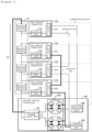
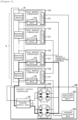
- FIG. 1 is a diagram schematically illustrating constituent elements of a battery module equalizing apparatus 100 according to an exemplary embodiment of the present invention.
- a battery module equalizing apparatus 100 includes a plurality of cell module controllers (CMCs) 110 and a battery module controller (BMC) 120.
- CMCs cell module controllers
- BMC battery module controller
- the CMCs 110 are connected to a plurality of battery modules 10, respectively. each among the CMCs 110 measures a voltage at ends of its respective connected battery module among the battery modules 10, respectively.
- the CMCs 110 will be described in more detail with reference to FIG. 2 .
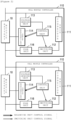
- FIG. 2 is a diagram illustrating the cell module controller 110 included in the battery module equalizing apparatus 100 according to the exemplary embodiment of the present invention in more detail.
- each of the CMCs 110 includes a switching unit 112, and may further include a connector unit 111, a voltage sensing unit 113, a balancing unit 114, a control unit 115, and a fuse unit 116.
- the connector unit 111 may internally connect a positive terminal of the battery module 10 connected to each of the CMCs 110 and the switching unit 112 included in each of the CMCs 110. Further, the connector unit 111 may externally selectively connect one or more of the positive terminal of the battery module 10 connected to each of the CMCs 110 and the switching unit 112 included in each of the CMCs 110 and an equalization BUS which is to be described below. To this end, the connector unit 111 may be formed by one or more connectors.
- the switching unit 112 may control an electrical conduction state between the connector unit 111 and a negative terminal of the batter module 10 connected to each CMC 110.
- the switching unit 112 may be a switching device, such as a relay, a contactor, a transistor, and a thyristor, and may control an electrical conduction state between the negative terminals of the battery modules 10 connected to the CMCs 110, respectively, according to the electrical conduction state of the switching device. Further, the switching unit 112 may be confirmed by one or more switching devices as necessary.
- the switching unit 112 included in each of the CMCs 110 may be maintained in an off state when abnormality of the battery module 10 is not diagnosed by the BMC 120 which is to be described below.
- the voltage sensing unit 113 may sense voltage values at both ends of the battery module 10 connected to each CMC 110.
- the voltage sensing unit 113 may be a shunt resistor, and transmit a voltage value applied to the shunt resistor to a control unit 115 which is to be described below.
- the present invention is not limited thereto.
- the voltage sensing unit 113 may provide the sensed voltage values at both ends of the battery module 10 to the BMC which is to be described below.
- the balancing unit 114 may additionally consume power of the connected battery module 10 based on the voltage value of the connected battery module 10.
- the balancing unit may include one or more switches (not illustrated) and one or more resistors (not illustrated).
- the balancing unit 114 may receive a balancing unit control signal from the control unit 115 which is to be described below and consume power of the battery module 10 in the form of heat by using the one or more resistors.
- the control unit 115 may output a switching unit control signal to the switching unit 112.
- the switching unit control signal may be a control signal that is capable of changing an electrical conduction state of the switching unit 112.
- the control unit 115 changes a state of the switch to an on-state based on the voltage value of the battery module 10 sensed in the voltage sensing unit 113, and consumes power by using the resistor included in the balancing unit 114, thereby enabling the balancing unit 114 to operate.
- control unit 115 is one integrated circuit and may include a micro controller unit (MCU) which is capable of controlling a plurality of constituent elements.
- MCU micro controller unit
- each of the CMCs 110 may further include a power unit (not illustrated).
- the power unit may reduce a voltage of the battery module 10 and provide the reduced voltage so as for the constituent elements included in CMCs 110 to operate.
- the control unit 115 is an MCU
- the power unit may reduce a voltage to 3 to 5 V that is a permitted voltage of the MCU and provide the reduced voltage to the control unit 115.
- the CMCs 110 are connected by a daisy chain connection scheme.
- the battery module equalizing apparatus 100 includes a communication BUS and the equalization BUS.
- the equalization BUS connects the CMCs 110 by the daisy chain connection scheme. To this end, the equalization BUS is configured by a positive BUS and a negative BUS.
- the negative BUS may be a BUS connected from the negative terminal of the battery module 10 located at the last.
- the negative BUS serially connects the CMCs 110 located at the even-numbered places based on the CMC 110 located at the last among the CMCs 110. For example, when the CMC 110 located at the last is set by number 1, the negative BUS may connect the second CMC 110, the fourth CMC 110, the sixth CMC 110, ..., and the N th CMC 110.
- the BMC 120 controls the switching units included in the CMCs 110, respectively, based on a location of the battery module which is diagnosed to have the abnormality among the battery modules 10, thereby forming an equalization current supply circuit that is a closed circuit including the BMC 120 and the battery module 10 which is diagnosed to have the abnormality. Further, the BMC 120 may supply an equalization current to the battery module 10 which is diagnosed to have the abnormality via the formed equalization current supply circuit.
- a series of processes of forming the equalization current supply circuit and supplying an equalization current to the battery module 10 having the abnormality via the formed equalization current supply circuit by the BMC 120 will be described with reference to FIGS. 3 and 4 .
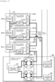
- FIG. 3 is a diagram schematically illustrating the equalization current supply circuit formed in the battery module equalizing apparatus 100 according to the exemplary embodiment of the present invention.
- the BMC 120 may supply an equalization current to the battery module 10 which is diagnosed to have abnormality via the equalization current supply circuit.
- the BMC 120 may include an equalization current supply unit 121.
- the equalization current supply unit 121 may receive a voltage from battery modules 10, convert the received voltage to a voltage having a predetermined size, and transmit the received voltage to the battery module 10 having the abnormality.
- the equalization current supply unit 121 may be an isolated converter, such as a DC-DC converter.
- the present invention is not limited thereto.
- the BMC 120 forms the equalization current supply circuit by controlling the switching unit 112 included in each of the CMCs 110 connected with the battery module 10 which is diagnosed to have the abnormality and the CMC 110 connected to a front end of the CMC 110 connected with the battery module 10 which is diagnosed to have the abnormality.
- the BMC 120 may output a control signal to the CMC 110-2 of number 2 and the CMC 110-3 of number 3.
- the control signal may be a signal controlling the control unit 115 included in CMCs 110 to output the switching control signal.
- control signal may be a signal directly controlling, by the BMC 120, an electrical conduction state of the switching unit 112 included in the CMCs 110.
- the CMC 110-2 of number 2 and the CMC 110-3 of number 3 may receive the control signal from the BMC 120, and control the conduction states of the switching units 112-2 and 112-3 included in the CMC 110-2 of number 2 and the CMC 110-3 of number 3, respectively, to be in an on-state.
- the BMC 120 may form the equalization current supply circuit illustrated in FIG. 3 , and the equalization current may be provided to the battery module 10-2 having the abnormality.
- the equalization current supply circuit may be formed with the connector unit 111-1 of number 1, the connector of number 3 111-3, the switching unit 112-3 of number 3, the negative terminal of the battery module 10-3 of number 3, the battery module 10-2 having the abnormality, the switching unit 112-2 of number 2, the connector unit 111-2 of number 2, and the equalization current supply unit 121.
- the equalization current supply unit 121 may provide the battery module 10-2 having the abnormality with the equalization current via the equalization current supply circuit formed as described above.
- FIG. 4 is a diagram schematically illustrating the equalization current supply circuit formed when abnormality of a battery module located at the first end is diagnosed in the battery module equalizing apparatus 100 according to the exemplary embodiment of the present invention.
- the BMC 120 may output a control signal to the CMC 110-n located at the first end and the auxiliary switching unit 122.
- the switching unit 112-n included in the CMC 110-n located at the first end and the auxiliary switching unit 122 may receive the control signal, and the states of the switching unit 112-n and the auxiliary switching unit 122 may be controlled to an on-state based on the control signal. Accordingly, the equalization current supply circuit illustrated in FIG. 4 is formed, thereby providing an equalization current to the battery module 10-n that has the abnormality and is located at the first end.
- the equalization current supply circuit may form the equalization current supply circuit including the auxiliary switching unit 122, the connector unit 111-n of the CMC 110-n located at the first end, the battery module 10-n located at the first end, the switching unit 112-n of the CMC 110-n located at the first end, the connector unit 111-n of the CMC 110-n located at the first end, and the connector unit 111-n-2 of the even-numbered CMC 110-n-2 based on the last end.
- the equalization current supply unit 121 may provide the battery module 10-n located at the first end with the equalization current via the equalization current supply circuit formed as described above.
- the BMC 120 may further include an equalization circuit switching unit 124 which is located at an output terminal of the equalization current supply unit 121 and changes an electrical conduction state of the output terminal of the equalization current supply unit 121.f
- the equalization current switching unit 124 may control the electrical conduction state of the output terminal of the equalization current supply unit 121 in order to form the equalization current supply circuit for supplying the equalization current to the battery module which is diagnosed to have the abnormality.
- the equalization circuit switching unit 124 may be four single pole single throw (SPST) switches as illustrated in FIGS. 1 , and 3 to 6 .
- SPST single pole single throw
- the present invention is not limited thereto, any constituent element which is capable of blocking an output voltage of the output terminal of the equalization current supply unit 121 may be applied.
- the BMC 120 may form a module location identifying circuit by controlling the switching unit 112 included in the CMC 110 of which a location is desired to be recognized among the CMCs 110. Further, the BMC may identify a location of the CMC 110 of which a location is desired to be recognized based on a voltage applied to the module location identifying circuit.
- this will be described in more detail with reference to FIGS. 5 and 6 .
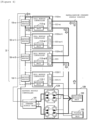
- FIG. 5 is a diagram schematically illustrating a module location identifying circuit formed in the battery module equalizing apparatus 100 according to the exemplary embodiment of the present invention
- FIG. 6 is a diagram schematically illustrating another form of the module location identifying circuit formed in the battery module equalizing apparatus 100 according to the exemplary embodiment of the present invention.
- the BMC 120 may form the module location identifying circuit by controlling the switching unit 112 of the CMC 110 of which a location is desired to be recognized, and identify a location of the corresponding CMC 110 based on a voltage of the formed module location identifying circuit.
- the BMC 120 may include a voltage measuring unit 123.
- a positive terminal of the voltage measuring unit 123 is connected with the positive BUS and a negative terminal of the voltage measuring unit 123 is connected with the negative BUS, thereby measuring a voltage applied to the module location identifying circuit.
- the BMC 120 may control an electrical conduction state of the switching unit 112 included in the CMC 110 of which a location is desired to be recognized, that is, the CMC 110 located at the front end of the CMC 110 located at the last end.
- the module location identifying circuit illustrated in FIG. 5 may be formed, and the module location identifying circuit may include only one battery module among N battery modules 10.
- the voltage applied to the module location identifying circuit measured via the voltage measuring unit 123 may be the voltage of one battery module.
- the BMC 120 may control an electrical conduction state of the switching unit 112 included in the third-placed CMC 110.
- the module location identifying circuit illustrated in FIG. 6 may be formed, and the module location identifying circuit may include N-2 battery modules among N battery modules 10. Accordingly, the voltage applied to the module location identifying circuit measured via the voltage measuring unit 123 may be the voltages of N-2 battery modules.
- the voltages of 0 V to 9 V may be measured according to the locations of 10 CMCs 110.
- the BMC 120 may pre-store a voltage value according to the locations of the CMCs 110, and may match the voltage measured via the voltage measuring unit 123 among the prestored voltage values with a corresponding voltage value and identify a location of the CMC 110 of which a location is desired to be recognized.
- the BMC 120 may form the module location identifying circuit for each of the CMCs 110 and measure a voltage via the voltage measuring unit 123, and assign an identification number to each of the CMCs 110 based on a size of the measured voltage.
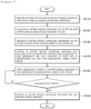
- FIG. 7 is a flowchart for describing a series of processes for equalizing the battery modules 10 by using the battery module equalizing apparatus 100 according to an exemplary embodiment of the present invention.
- the BMC may receive the voltages of both ends of the battery module measured in operation S110 and calculate an SoC of each of the battery modules (S120).
- the BMC diagnoses abnormality of the SoC of each of the battery modules based on the calculated SoC of the battery modules (S130).
- the states of the switching units included in the CMC connected with the battery module which is diagnosed to have the abnormality and the CMC connected to the front end of the corresponding CMC are controlled to an on-state to form an equalization current supply circuit (S140).
- the equalization current supply unit supplies an equalization current to the battery module having the abnormality via the equalization current supply circuit formed in operation S140 (S150).
- the equalization current is supplied in operation S150, so that when the SoC of the battery modules is equalized and has no abnormality, the BMC controls the states of the switching units included in the CMC connected with the battery module which is diagnosed to have the abnormality and the CMC connected to the front end of the corresponding CMC to an off state and performs a normal operation S160.
- the SoC of the battery modules may be equalized by repeatedly performing operation S150.
- the BMC controls a state of a switching unit included in a CMC of which a location is desired to be recognized to an on-state and forms a module location identifying circuit (S210).
- the BMC measures a voltage applied to the module location identifying circuit formed in operation S210 via the voltage measuring unit (S220).
- the BMC matches a CMC corresponding to the voltage measured via the voltage measuring unit among the CMCs (S230).
- the BMC recognizes a location of the CMC of which the location is desired to be recognized based on the CMC matched in operation S230.
Landscapes
- Engineering & Computer Science (AREA)
- Power Engineering (AREA)
- Manufacturing & Machinery (AREA)
- Chemical & Material Sciences (AREA)
- Chemical Kinetics & Catalysis (AREA)
- Electrochemistry (AREA)
- General Chemical & Material Sciences (AREA)
- Charge And Discharge Circuits For Batteries Or The Like (AREA)
- Secondary Cells (AREA)
- Tests Of Electric Status Of Batteries (AREA)
Claims (9)
- Vorrichtung für ein Ausgleichen eines Batteriemoduls (10-1, ..., 10-n), wobei die Vorrichtung umfasst:eine Mehrzahl (110) von Zellmodul-Steuerungen, CMCs (110-1, ..., 110-n), welche jeweils mit einer Mehrzahl (10) von Batteriemodulen (10-1, ..., 10-n) verbunden sind, wobei jede CMC (110-1, ..., 110-n) dazu eingerichtet ist, eine Spannung an Enden von dessen jeweiligen verbundenen Batteriemoduls (10-1, ..., 10-n) unter der Mehrzahl (10) von Batteriemodulen (10-1, ..., 10-n) zu messen, undeine Batteriemodul-Steuerung, BMC (120), welche dazu eingerichtet ist, einen Zustand einer Ladung, SoC, von jeder der Mehrzahl (10) von Batteriemodulen (10-1, ... , 10-n) zu berechnen, auf Grundlage der gemessenen Spannungen an Enden von jedem der Batteriemodule (10-1, ..., 10-n), wobei die BMC (120) dazu eingerichtet ist, eine Unregelmäßigkeit von jeder der Mehrzahl (10) von Batteriemodulen (10-1, ..., 10-n) auf Grundlage des berechneten SoC zu bestimmen,wobei die BMC (120) dazu eingerichtet ist, eine Mehrzahl von Schalteinheiten (112-1, ..., 112-n) zu steuern, welche jeweils in der Mehrzahl (110) der CMCs (110-1, ..., 110-n) umfasst sind, auf Grundlage einer Position des Batteriemoduls (10-2), für welches es bestimmt worden ist, dass es die Unregelmäßigkeit unter der Mehrzahl (10) von Batteriemodulen (10-1, ..., 10-n) aufweist,wobei die BMC (120) dazu eingerichtet ist, die Steuerung durchzuführen durch ein Bilden einer Ausgleich-Stromversorgungsschaltung, welche eine geschlossene Schaltung ist, welche die BMC (120) und das Batteriemodul (10-2) umfasst, für welches es bestimmt worden ist, dass es die Unregelmäßigkeit aufweist, und ein Versorgen des Batteriemoduls (10-2), für welches es bestimmt worden ist, dass es die Unregelmäßigkeit aufweist, mit einem Ausgleichsstrom über die Ausgleich-Stromversorgungsschaltung,wobei die Vorrichtung umfasst:einen Ausgleich-BUS und einen Kommunikation-BUS, welche die Mehrzahl (110) der CMCs (110-1, ..., 110-n) und die BMC (120) durch ein Verkettungsverbindungsschema verbinden,wobei der Ausgleich-BUS umfasst:einen positiven BUS, welcher eine Mehrzahl der CMCs (110-1, 110-3) seriell verbindet, welche sich an ungerade-nummerierten Plätzen befinden, wobei der erste Platz an der CMC (110-1) ist, welche sich an dem letzten Ende unter der Mehrzahl (110) der CMCs (110-1, ..., 110-n) befindet; undeinen negativen BUS, welcher eine Mehrzahl der CMCs (110-2) seriell verbindet, welche sich an gerade-nummerierten Plätzen befinden,wobei die BMC (120) dazu eingerichtet ist, die Ausgleich-Stromversorgungsschaltung zu bilden, durch ein Steuern der Schalteinheit (112-2), welche in der CMC (110-2) umfasst ist, welche mit dem Batteriemodul (10-2) verbunden ist, für welches es bestimmt worden ist, dass es die Unregelmäßigkeit aufweist, um sie in einen An-Zustand einzustellen, und der Schalteinheit (112-3) welche in der CMC (110-3) umfasst ist, welche mit einem vorderen Ende der CMC (110-2) verbunden ist, welche mit dem Batteriemodul (10-2) verbunden ist, für welches es bestimmt worden ist, dass es die Unregelmäßigkeit aufweist, um sie in einen An-Zustand einzustellen.
- Vorrichtung nach Anspruch 1; wobei, wenn die Unregelmäßigkeit nicht in der Mehrzahl (10) der Batteriemodule (10-1, ..., 10-n) bestimmt ist, die Mehrzahl (110) der CMCs (110-1, ..., 110-n) dazu eingerichtet sind, die Mehrzahl der Schalteinheiten (112-1, ..., 112-n) in einem Aus-Zustand zu halten.
- Vorrichtung nach Anspruch 1; wobei die BMC (120) eine Hilfsschalteinheit (122) umfasst, welche dazu eingerichtet ist, einen elektrischen Leitungszustand mit einer CMC (110-n) zu steuern, welche sich an dem ersten Ende unter der Mehrzahl (110) der CMCs (110-1, ..., 110-n) befindet, und
wenn es bestimmt ist, dass ein Batteriemodul (10-n), welches sich an dem ersten Ende befindet, eine Unregelmäßigkeit aufweist, die BMC (120) dazu eingerichtet ist, die Ausgleich-Stromversorgungsschaltung zu bilden, um das Batteriemodul (10-n), welches sich an dem ersten Ende befindet, durch ein Steuern elektrischer Leitungszustände der Schalteinheit (112-n), welche in der CMC umfasst ist, welche sich an dem ersten Ende befindet, und die Hilfsschalteinheit (122) zu umfassen. - Vorrichtung nach Anspruch 1; wobei jedes aus der Mehrzahl (10) der CMCs (110-1, ..., 110-n) ferner umfasst:eine Verbindungseinheit (111-1, ..., 111-n), welche dazu eingerichtet ist, das Batteriemodul (10-1, ..., 10-n), welches mit jeder der CMCs (110-1, ..., 110-n) verbunden ist, die Schalteinheit (112-1, ..., 112-n), welche in jeder der CMCs (110-1, ..., 110-n) umfasst ist, und den Ausgleich-BUS selektiv zu verbinden;eine Spannungserkennungseinheit (113), welche dazu eingerichtet ist, die Spannung an Enden des Batteriemoduls (10-1, ..., 10-n) zu messen, welches mit jeder der CMCs (110-1, ..., 110-n) verbunden ist;eine Sicherungseinheit (116), welche eine negative Elektrode des Batteriemoduls (10-1, ..., 10-n), welches mit jeder der CMCs (110-1, ..., 110-n) verbunden ist, und die eine oder mehr Schalteinheiten (112-1, ..., 112-n) verbindet;eine Abgleicheinheit (114), welche dazu eingerichtet ist, das Batteriemodul (10-1, ..., 10-n) zu entladen, welches mit jeder der CMCs (110-1, ..., 110-n) verbunden ist; undeine Steuerungseinheit (115), welche dazu eingerichtet ist, einen Betrieb der Abgleicheinheit (114) auf Grundlage der gemessenen Spannung zu steuern.
- Vorrichtung nach Anspruch 1; wobei die BMC (120) umfasst:eine Ausgleichsstrom-Versorgungseinheit (121), welche dazu eingerichtet ist, das Batteriemodul (10-2), für welches es bestimmt worden ist, dass es die Unregelmäßigkeit aufweist, mit dem Ausgleichsstrom zu versorgen; undeine Spannungsmesseinheit (123), welche dazu eingerichtet ist, eine Spannung des Ausgleich-BUS zu messen, undpositive Anschlüsse der Ausgleichsstrom- Versorgungseinheit (121) und der Spannungsmesseinheit (123) mit dem positiven BUS verbunden sind, und negative Anschlüsse der Ausgleichsstrom-Versorgungseinheit (121) und der Spannungsmesseinheit (123) mit dem negativen BUS verbunden sind.
- Vorrichtung nach Anspruch 1; wobei die BMC (120) dazu eingerichtet ist, eine Modulposition-Identifizierung-Schaltung durch ein Steuern einer Schalteinheit (112-1, ..., 112-n) auszubilden, welche in einer CMC (110-1, ..., 110-n) umfasst ist, deren Positionsbestimmung unter der einen oder mehr CMCs (110-1, ..., 110-n) erwünscht ist, und dazu eingerichtet ist, die Position der CMC, deren Positionsbestimmung erwünscht ist, auf Grundlage einer Spannung, welche an der Modulposition-Identifizierung-Schaltung angelegt ist, zu identifizieren.
- Verfahren eines Ausgleichens eines Batteriemoduls durch die Batteriemodul-Ausgleichsvorrichtung nach einem der Ansprüche 1 bis 6, wobei das Verfahren umfasst:Messen von Spannungen an Enden der Mehrzahl von Batteriemodulen (10-1, ..., 10-n), welche jeweils mit der Mehrzahl von CMCs (110-1, ..., 110-n) verbunden sind;Bestimmen einer Unregelmäßigkeit von jeder der Mehrzahl (10) der Batteriemodule (10-1, ..., 10-n) auf Grundlage der SoCs von jeder der Mehrzahl (10) der Batteriemodule (10-1, ..., 10-n), welche auf Grundlage der gemessenen Spannungen an Enden von jeder der Mehrzahl (10) der Batteriemodule (10-1, ..., 10-n) berechnet werden, undSteuern der Mehrzahl von Schalteinheiten (112-1, ..., 112-n), welche jeweils in der Mehrzahl (110) der CMCs (110-1, ..., 110-n) umfasst sind, auf Grundlage der Position des Batteriemoduls (10-2), für welches es bestimmt wird, dass es die Unregelmäßigkeit unter der Mehrzahl (10) von Batteriemodulen (10-1, ..., 10-n) aufweist, und Bilden einer Ausgleich-Stromversorgungsschaltung, welche eine geschlossene Schaltung ist, welche eine Ausgleich-Stromversorgungseinheit (121), welche einen Ausgleichsstrom bereitstellt, und das Batteriemodul (10-2) umfasst, für welches es bestimmt wird, dass es die Unregelmäßigkeit aufweist,wobei das Bereitstellen des Ausgleichsstroms ein Bilden der Ausgleich-Stromversorgungsschaltung, durch ein Steuern der Schalteinheit (112-2) umfasst, welche in den CMCs (110-2) umfasst ist, welche mit dem Batteriemodul (10-2) verbunden sind, für welches es bestimmt wird, dass es die Unregelmäßigkeit aufweist, um sie in den An-Zustand einzustellen, und der Schalteinheit (112-3) welche in der CMC (110-3) umfasst ist, welche mit einem vorderen Ende der CMC (110-2) verbunden ist, welche mit dem Batteriemodul (10-2) verbunden ist, für welches es bestimmt wird, dass es die Unregelmäßigkeit aufweist, um sie in den An-Zustand einzustellen.
- Verfahren nach Anspruch 7, ferner umfassend:
wenn die Unregelmäßigkeit in der Mehrzahl (10) der Batteriemodule (10-1, ..., 10-n) nicht bestimmt wird, Halten der Mehrzahl der Schalteinheiten (112-1, ..., 112-n) in dem Aus-Zustand. - Verfahren nach Anspruch 7 für die Batteriemodul-Ausgleichsvorrichtung nach Anspruch 3, wobei das Bereitstellen des Ausgleichsstroms umfasst, wenn es bestimmt wird, dass das Batteriemodul (10-n), welches sich an dem ersten Ende befindet, eine Unregelmäßigkeit aufweist, Bilden der Ausgleich-Stromversorgungsschaltung, um das Batteriemodul (10-n), welches sich an dem ersten Ende befindet, durch ein Steuern elektrischer Leitungszustände der Schalteinheit (112-n), welche in der CMC (110-n) umfasst ist, welche sich an dem ersten Ende befindet, und die Hilfsschalteinheit (122), welche mit einem der CMC (110-2) verbunden ist, zu umfassen, welche sich an dem ersten Ende unter der Mehrzahl der CMCs (110-1, ..., 110-n) befindet.
Applications Claiming Priority (3)
| Application Number | Priority Date | Filing Date | Title |
|---|---|---|---|
| KR20170064203 | 2017-05-24 | ||
| KR1020170090340A KR102150147B1 (ko) | 2017-05-24 | 2017-07-17 | 배터리 모듈 균등화 장치 및 방법 |
| PCT/KR2018/000412 WO2018216874A1 (ko) | 2017-05-24 | 2018-01-09 | 배터리 모듈 균등화 장치 및 방법 |
Publications (3)
| Publication Number | Publication Date |
|---|---|
| EP3540900A1 EP3540900A1 (de) | 2019-09-18 |
| EP3540900A4 EP3540900A4 (de) | 2019-12-11 |
| EP3540900B1 true EP3540900B1 (de) | 2025-06-25 |
Family
ID=64669269
Family Applications (1)
| Application Number | Title | Priority Date | Filing Date |
|---|---|---|---|
| EP18806502.3A Active EP3540900B1 (de) | 2017-05-24 | 2018-01-09 | Vorrichtung und verfahren zur batteriemodulentzerrung |
Country Status (7)
| Country | Link |
|---|---|
| US (1) | US11177669B2 (de) |
| EP (1) | EP3540900B1 (de) |
| JP (1) | JP6787631B2 (de) |
| KR (1) | KR102150147B1 (de) |
| CN (1) | CN110024256B (de) |
| ES (1) | ES3037021T3 (de) |
| HU (1) | HUE072355T2 (de) |
Families Citing this family (22)
| Publication number | Priority date | Publication date | Assignee | Title |
|---|---|---|---|---|
| KR102236384B1 (ko) * | 2017-10-27 | 2021-04-05 | 주식회사 엘지화학 | 배터리 밸런싱을 위한 장치 및 그것을 포함하는 배터리팩 |
| KR102443667B1 (ko) * | 2018-10-26 | 2022-09-14 | 주식회사 엘지에너지솔루션 | 밸런싱 장치, 및 그것을 포함하는 배터리 관리 시스템과 배터리팩 |
| KR102248227B1 (ko) | 2019-01-10 | 2021-05-03 | 주식회사 엘지화학 | 배터리 밸런싱 장치, 방법 및 이를 포함하는 배터리 팩 |
| KR102170505B1 (ko) * | 2019-11-28 | 2020-10-28 | 이승호 | 태양광 발전을 이용한 에너지 저장 장치 |
| US11476677B2 (en) | 2020-06-02 | 2022-10-18 | Inventus Power, Inc. | Battery pack charge cell balancing |
| US11588334B2 (en) | 2020-06-02 | 2023-02-21 | Inventus Power, Inc. | Broadcast of discharge current based on state-of-health imbalance between battery packs |
| US12224603B2 (en) | 2020-06-02 | 2025-02-11 | Inventus Power, Inc. | Mode-based disabling of communication bus of a battery management system |
| US11489343B2 (en) | 2020-06-02 | 2022-11-01 | Inventus Power, Inc. | Hardware short circuit protection in a large battery pack |
| US11411407B1 (en) | 2021-02-24 | 2022-08-09 | Inventus Power, Inc. | Large-format battery management systems with gateway PCBA |
| US11245268B1 (en) | 2020-07-24 | 2022-02-08 | Inventus Power, Inc. | Mode-based disabling of communiction bus of a battery management system |
| US11133690B1 (en) | 2020-06-02 | 2021-09-28 | Inventus Power, Inc. | Large-format battery management system |
| US11552479B2 (en) | 2020-06-02 | 2023-01-10 | Inventus Power, Inc. | Battery charge balancing circuit for series connections |
| US11404885B1 (en) | 2021-02-24 | 2022-08-02 | Inventus Power, Inc. | Large-format battery management systems with gateway PCBA |
| US12301031B1 (en) | 2020-06-02 | 2025-05-13 | Inventus Power, Inc. | Large-format battery management systems with gateway PCBA |
| US11509144B2 (en) | 2020-06-02 | 2022-11-22 | Inventus Power, Inc. | Large-format battery management system with in-rush current protection for master-slave battery packs |
| US11594892B2 (en) | 2020-06-02 | 2023-02-28 | Inventus Power, Inc. | Battery pack with series or parallel identification signal |
| CN114008889B (zh) * | 2021-06-18 | 2024-09-20 | 武汉领普科技有限公司 | 供电电路、传感设备及其应用 |
| CN115833875B (zh) * | 2022-01-18 | 2023-11-17 | 宁德时代新能源科技股份有限公司 | 一种菊花链通讯故障检测方法、定位检测方法和电路 |
| CN114528240B (zh) * | 2022-01-25 | 2024-08-06 | 阳光储能技术有限公司 | 一种菊花链通信控制方法及装置 |
| CN115020843B (zh) * | 2022-06-30 | 2026-01-06 | 郑州比克电池有限公司 | 一种改善硅氧体系电压一致性的方法 |
| KR102684542B1 (ko) * | 2023-10-25 | 2024-07-12 | 주식회사 오토기기 | 모듈 충방전 양방향 드라이버와 셀 충방전이 동시에 제어가 가능한 배터리 밸런스 장치 |
| CN118412623B (zh) * | 2024-06-26 | 2024-10-11 | 杭州协能科技股份有限公司 | 一种储能装置及其采样控制方法 |
Family Cites Families (76)
| Publication number | Priority date | Publication date | Assignee | Title |
|---|---|---|---|---|
| US6184656B1 (en) * | 1995-06-28 | 2001-02-06 | Aevt, Inc. | Radio frequency energy management system |
| US5631534A (en) * | 1995-08-21 | 1997-05-20 | Delco Electronics Corp. | Bidirectional current pump for battery charge balancing |
| US7400113B2 (en) * | 2001-03-30 | 2008-07-15 | Designline International Holdings, Llc | Battery management unit, system and method |
| US6583602B2 (en) * | 2001-05-11 | 2003-06-24 | Denso Corporation | Vehicular power supply apparatus and method of controlling the same |
| US7245108B2 (en) * | 2002-11-25 | 2007-07-17 | Tiax Llc | System and method for balancing state of charge among series-connected electrical energy storage units |
| DE102004031216A1 (de) * | 2004-06-28 | 2006-01-19 | Siemens Ag | Vorrichtung und Verfahren zum Ladungsausgleich in Reihe geschalteter Energiespeicher |
| CN101184994B (zh) * | 2005-04-05 | 2010-11-17 | 能量控制系统工程公司 | 复用器和基于开关的电化学电池监测器以及管理系统和方法 |
| JP4484858B2 (ja) * | 2006-10-19 | 2010-06-16 | 日立ビークルエナジー株式会社 | 蓄電池管理装置およびそれを備える車両制御装置 |
| CN101119036B (zh) * | 2007-07-23 | 2011-01-19 | 柏禄帕迅能源科技有限公司 | 用于电动汽车的电池管理系统 |
| KR101107999B1 (ko) * | 2007-10-16 | 2012-01-25 | 한국과학기술원 | 전압 센서와 전하 균일 장치가 결합된 배터리 운용 시스템 |
| KR101164629B1 (ko) * | 2007-10-16 | 2012-07-11 | 한국과학기술원 | 직렬 연결 배터리 스트링을 위한 2단 전하 균일 방법 및장치 |
| WO2009076418A1 (en) * | 2007-12-11 | 2009-06-18 | Antonio Trigiani | Battery management system |
| KR101156977B1 (ko) * | 2007-12-31 | 2012-06-20 | 에스케이이노베이션 주식회사 | 고전압 배터리 팩의 셀 밸런싱 방법 |
| KR101077154B1 (ko) * | 2008-04-22 | 2011-10-27 | 한국과학기술원 | 직렬연결 배터리 스트링을 위한 2단 전하 균일 방법 및장치 |
| KR101187766B1 (ko) * | 2008-08-08 | 2012-10-05 | 주식회사 엘지화학 | 배터리 셀의 전압 변화 거동을 이용한 셀 밸런싱 장치 및 방법 |
| US8294421B2 (en) * | 2008-09-05 | 2012-10-23 | O2Micro Inc | Cell balancing systems employing transformers |
| JP5448408B2 (ja) | 2008-10-15 | 2014-03-19 | 三菱重工業株式会社 | 二次電池制御システム |
| US8396609B2 (en) * | 2008-11-07 | 2013-03-12 | Sakti3, Inc. | Control of cells, modules and a pack comprised of hybridized electrochemistries |
| KR101093597B1 (ko) * | 2009-01-30 | 2011-12-15 | 한국과학기술원 | 정전압원을 이용한 자동전하균일 장치 |
| KR101076786B1 (ko) * | 2009-01-30 | 2011-10-25 | 한국과학기술원 | 직렬연결 배터리 스트링을 위한 지능제어 전하균일 장치 및방법 |
| US20100225277A1 (en) * | 2009-03-06 | 2010-09-09 | Asic Advantage Inc. | Battery charge and discharge controller |
| JP5133926B2 (ja) * | 2009-03-26 | 2013-01-30 | 株式会社日立製作所 | 車両用電池システム |
| US8390147B2 (en) * | 2009-05-13 | 2013-03-05 | Solar Semiconductor, Inc. | Methods and apparatuses for photovoltaic power management |
| CN104135219B (zh) * | 2009-05-19 | 2016-12-07 | 最大输出可再生能源公司 | 包括发电装置的集群的电站的构造 |
| JP2011072153A (ja) * | 2009-09-28 | 2011-04-07 | Sanyo Electric Co Ltd | 車両用電源装置及びこれを備える車両並びに車両用電源装置の容量均等化方法 |
| KR101000550B1 (ko) | 2009-11-30 | 2010-12-14 | 정윤이 | 배터리 팩과 이를 포함한 능동형 셀 발란싱 배터리 관리장치 |
| CN102027628B (zh) * | 2009-11-30 | 2014-05-14 | 郑润珥 | 电池组及包含该电池组的主动型单电池平衡电池管理装置 |
| US20110144840A1 (en) * | 2009-12-15 | 2011-06-16 | Ise Corporation | Expandable Energy Storage Control System and Method |
| FR2956260B1 (fr) * | 2010-02-05 | 2012-04-13 | Commissariat Energie Atomique | Systeme d'equilibrage de charge pour batteries |
| KR101234059B1 (ko) * | 2010-02-22 | 2013-02-15 | 주식회사 엘지화학 | 셀 밸런싱부의 고장 진단 장치 및 방법 |
| JP5546370B2 (ja) * | 2010-06-28 | 2014-07-09 | 日立ビークルエナジー株式会社 | 蓄電器制御回路及び蓄電装置 |
| JP5571485B2 (ja) * | 2010-07-14 | 2014-08-13 | 矢崎総業株式会社 | 組電池の電圧均等化装置 |
| JP5567956B2 (ja) * | 2010-09-16 | 2014-08-06 | 矢崎総業株式会社 | 複数組電池のセル電圧均等化装置 |
| KR20120077482A (ko) * | 2010-12-30 | 2012-07-10 | 최두진 | 배터리 모듈의 균등 충전장치 |
| DE102011009474A1 (de) * | 2011-01-26 | 2012-07-26 | Liebherr-Elektronik Gmbh | Vorrichtung und Verfahren zum Überwachen und Symmetrieren eines mehrzelligen Energiespeicherstapels |
| EP2490315A1 (de) * | 2011-02-15 | 2012-08-22 | austriamicrosystems AG | Zellausgleichsmodul, Spannungsausgleichsvorrichtung und Verfahren zum Spannungsausgleich, insbesondere zum Spannungsausgleich eines Batteriestapels |
| JP5469625B2 (ja) * | 2011-03-01 | 2014-04-16 | 株式会社日立製作所 | 電池システム |
| EP2688175A4 (de) * | 2011-03-14 | 2014-09-17 | Sanyo Electric Co | Kommunikationssystem und akku-system |
| EP2684243B1 (de) * | 2011-03-17 | 2019-08-21 | Ev Chip Energy Ltd | Batteriepacksystem |
| WO2012132220A1 (ja) * | 2011-03-31 | 2012-10-04 | ルネサスエレクトロニクス株式会社 | 電圧監視モジュール及びこれを用いた電圧監視システム |
| US20140042974A1 (en) * | 2011-04-22 | 2014-02-13 | Sk Innovation Co., Ltd. | Detachable battery module, and method and apparatus for the charge equalization of a battery string using same |
| US8970162B2 (en) * | 2011-07-12 | 2015-03-03 | Texas Instruments Incorporated | System and method for balancing electrical energy storage devices via differential power bus and capacitive load switched-mode power supply |
| US8947048B2 (en) * | 2011-07-29 | 2015-02-03 | Infineon Technologies Ag | Power supply system with charge balancing |
| CN102957172B (zh) * | 2011-08-23 | 2015-04-22 | 福建睿能科技股份有限公司 | 一种多节串联锂电池组均衡及保护系统 |
| US9203121B2 (en) * | 2011-10-12 | 2015-12-01 | Texas Instruments Incorporated | Inductor-based active balancing for batteries and other power supplies |
| KR101497602B1 (ko) * | 2012-05-02 | 2015-03-03 | 주식회사 엘지화학 | 배터리 밸런싱 시스템 및 이를 이용한 배터리 밸런싱 방법 |
| KR101402802B1 (ko) | 2012-05-03 | 2014-06-03 | 주식회사 엘지화학 | 배터리 셀의 전압 변화 거동을 이용한 셀 밸런싱 장치 및 방법 |
| KR101942970B1 (ko) | 2012-09-21 | 2019-01-28 | 삼성전자주식회사 | 밸런싱 방법 및 배터리 시스템 |
| KR101387658B1 (ko) * | 2012-10-31 | 2014-04-24 | 한국전기연구원 | 에너지 절감형 배터리 모듈의 셀 밸런싱 방법 |
| JP5693547B2 (ja) | 2012-11-20 | 2015-04-01 | 三菱重工業株式会社 | 電池管理装置およびその制御方法ならびにプログラム、それを備えた電池監視システム |
| KR20140070149A (ko) | 2012-11-30 | 2014-06-10 | 에스케이이노베이션 주식회사 | 배터리 모듈의 셀 밸런싱 장치 및 그 방법 |
| KR101865969B1 (ko) | 2012-12-17 | 2018-06-11 | 현대자동차주식회사 | 배터리전압 밸런싱장치 및 방법 |
| KR101589198B1 (ko) * | 2013-02-19 | 2016-01-28 | 주식회사 엘지화학 | 셀 밸런싱 회로의 고장 진단 장치 및 방법 |
| KR102028923B1 (ko) | 2013-04-11 | 2019-10-08 | 에스케이이노베이션 주식회사 | 배터리 밸런싱 장치 및 방법 |
| CN103199589B (zh) * | 2013-04-12 | 2014-12-10 | 哈尔滨工业大学 | 一种锂离子电池组模块化快速均衡电路及均衡方法 |
| US9927492B2 (en) * | 2013-05-29 | 2018-03-27 | Nxp Usa, Inc. | Cell monitoring apparatus, battery monitoring apparatus, integrated circuit and method of monitoring a rechargeable cell |
| US9520613B2 (en) * | 2013-07-23 | 2016-12-13 | Infineon Technologies Ag | Battery control with block selection |
| US9923399B2 (en) * | 2013-08-06 | 2018-03-20 | Analog Devices, Inc. | Battery stack with distributed control of cells driving events |
| JP2015065796A (ja) | 2013-09-26 | 2015-04-09 | ソニー株式会社 | 蓄電装置、蓄電制御装置および蓄電制御方法 |
| US20150102943A1 (en) * | 2013-10-10 | 2015-04-16 | Datang Nxp Semiconductors Co., Ltd. | Daisy-chain communication bus and protocol |
| JP6049603B2 (ja) * | 2013-12-19 | 2016-12-21 | 株式会社日立製作所 | 電池制御システム及び電池制御方法 |
| DE102014214996A1 (de) * | 2014-07-30 | 2016-02-04 | Robert Bosch Gmbh | Verfahren zum Betrieb eines Batteriesystems |
| KR101712244B1 (ko) | 2014-10-08 | 2017-03-13 | 주식회사 엘지화학 | 엘씨 공진을 이용한 배터리 셀 밸런싱 시스템 및 방법 |
| US10293693B2 (en) * | 2015-04-21 | 2019-05-21 | Samsung Electronics Co., Ltd. | Battery control method and apparatus, battery module, and battery pack |
| KR102206931B1 (ko) * | 2015-06-30 | 2021-01-22 | 가부시키가이샤 지에스 유아사 | 제어 장치, 축전 장치, 축전 시스템, 이동체 및 백업용 전원, 그리고 제어 방법 |
| KR101917913B1 (ko) * | 2015-07-23 | 2018-11-12 | 주식회사 엘지화학 | 배터리 스택 밸런싱 장치 |
| CN105259494B (zh) * | 2015-10-27 | 2018-04-03 | 北京新能源汽车股份有限公司 | 电池均衡电路的测试装置及方法 |
| KR102052241B1 (ko) * | 2016-09-21 | 2019-12-04 | 주식회사 엘지화학 | 밸런싱 배터리를 이용한 배터리 관리 시스템 및 방법 |
| KR102137759B1 (ko) * | 2017-07-06 | 2020-07-24 | 주식회사 엘지화학 | 배터리 팩 관리 장치 |
| KR102173777B1 (ko) * | 2017-07-25 | 2020-11-03 | 주식회사 엘지화학 | 마스터 배터리 관리 유닛 및 이를 포함하는 배터리팩 |
| KR102173778B1 (ko) * | 2017-07-25 | 2020-11-03 | 주식회사 엘지화학 | 배터리 관리 유닛 및 이를 포함하는 배터리팩 |
| KR102202613B1 (ko) * | 2017-09-27 | 2021-01-12 | 주식회사 엘지화학 | 배터리 모듈 균등화 장치, 이를 포함하는 배터리 팩 및 자동차 |
| KR102236384B1 (ko) * | 2017-10-27 | 2021-04-05 | 주식회사 엘지화학 | 배터리 밸런싱을 위한 장치 및 그것을 포함하는 배터리팩 |
| KR102308299B1 (ko) * | 2017-11-06 | 2021-10-01 | 주식회사 엘지에너지솔루션 | 셀 모듈 균등화 및 프리차지 장치 및 방법 |
| KR102180138B1 (ko) * | 2017-11-24 | 2020-11-17 | 주식회사 엘지화학 | 무선 배터리 관리 시스템 및 그것을 이용하여 배터리팩을 보호하는 방법 |
| KR102374744B1 (ko) * | 2018-10-16 | 2022-03-14 | 주식회사 엘지에너지솔루션 | 배터리 모듈 밸런싱 장치 및 방법 |
-
2017
- 2017-07-17 KR KR1020170090340A patent/KR102150147B1/ko active Active
-
2018
- 2018-01-09 JP JP2019527548A patent/JP6787631B2/ja active Active
- 2018-01-09 US US16/462,403 patent/US11177669B2/en active Active
- 2018-01-09 ES ES18806502T patent/ES3037021T3/es active Active
- 2018-01-09 EP EP18806502.3A patent/EP3540900B1/de active Active
- 2018-01-09 HU HUE18806502A patent/HUE072355T2/hu unknown
- 2018-01-09 CN CN201880004638.9A patent/CN110024256B/zh active Active
Also Published As
| Publication number | Publication date |
|---|---|
| EP3540900A1 (de) | 2019-09-18 |
| JP2020513721A (ja) | 2020-05-14 |
| HUE072355T2 (hu) | 2025-11-28 |
| KR102150147B1 (ko) | 2020-09-01 |
| CN110024256A (zh) | 2019-07-16 |
| CN110024256B (zh) | 2023-04-28 |
| KR20180128817A (ko) | 2018-12-04 |
| US11177669B2 (en) | 2021-11-16 |
| EP3540900A4 (de) | 2019-12-11 |
| JP6787631B2 (ja) | 2020-11-18 |
| US20190356140A1 (en) | 2019-11-21 |
| ES3037021T3 (en) | 2025-09-26 |
Similar Documents
| Publication | Publication Date | Title |
|---|---|---|
| EP3540900B1 (de) | Vorrichtung und verfahren zur batteriemodulentzerrung | |
| EP2418751B1 (de) | Batterieladegerät und Batterieladeverfahren | |
| RU2484491C1 (ru) | Устройство мониторинга напряжения аккумулятора | |
| US8466657B2 (en) | Autonomous balancing of series connected charge storage devices | |
| US7911179B2 (en) | Charging/discharging apparatus | |
| US9112360B2 (en) | Power supply device | |
| EP3076516B1 (de) | Batteriezellenausgleichsystem und -verfahren unter verwendung von lc-resonanz | |
| DK2368304T3 (en) | Energy storage device and method to provide such a device | |
| EP3349321B1 (de) | Batterieüberwachungsvorrichtung | |
| EP2161810A1 (de) | Batteriezellausgleichsystem mit einem Transformator | |
| US20090267565A1 (en) | Method and system for cell equalization with charging sources and shunt regulators | |
| US20060097696A1 (en) | Method and system for cell equalization with isolated charging sources | |
| US9236753B2 (en) | Power source device and method of controlling assembled battery | |
| CN106536261A (zh) | 电池组系统和用于运行电池组系统的方法 | |
| US9350168B2 (en) | Voltage equalization apparatus for connecting power storage unit racks and power storage system including the same | |
| CN114556739A (zh) | 用于电池架的单独放电系统和方法 | |
| CN110679055B (zh) | 单体模块均衡和预充电设备和方法 | |
| EP3337002B1 (de) | Batteriesystem und steuereinheit für ein batteriesystem | |
| KR20180035080A (ko) | 배터리 셀 밸런싱 회로 | |
| US20120256593A1 (en) | Cell charge management system | |
| CN110816311A (zh) | 用于运行电池组系统的方法和电动车辆 | |
| CN108336779A (zh) | 蓄电池模块及具备其的蓄电池系统 | |
| KR102818350B1 (ko) | 배터리 모듈, 배터리 관리 시스템 및 방법 | |
| KR20240145348A (ko) | 배터리 모듈 및 이의 동작 방법 | |
| CN104600377A (zh) | 电化学蓄能器和操控电化学蓄能器中的电池模块的方法 |
Legal Events
| Date | Code | Title | Description |
|---|---|---|---|
| STAA | Information on the status of an ep patent application or granted ep patent |
Free format text: STATUS: THE INTERNATIONAL PUBLICATION HAS BEEN MADE |
|
| PUAI | Public reference made under article 153(3) epc to a published international application that has entered the european phase |
Free format text: ORIGINAL CODE: 0009012 |
|
| STAA | Information on the status of an ep patent application or granted ep patent |
Free format text: STATUS: REQUEST FOR EXAMINATION WAS MADE |
|
| 17P | Request for examination filed |
Effective date: 20190614 |
|
| AK | Designated contracting states |
Kind code of ref document: A1 Designated state(s): AL AT BE BG CH CY CZ DE DK EE ES FI FR GB GR HR HU IE IS IT LI LT LU LV MC MK MT NL NO PL PT RO RS SE SI SK SM TR |
|
| AX | Request for extension of the european patent |
Extension state: BA ME |
|
| A4 | Supplementary search report drawn up and despatched |
Effective date: 20191111 |
|
| RIC1 | Information provided on ipc code assigned before grant |
Ipc: H02J 7/00 20060101AFI20191105BHEP Ipc: H01M 10/42 20060101ALI20191105BHEP |
|
| DAV | Request for validation of the european patent (deleted) | ||
| DAX | Request for extension of the european patent (deleted) | ||
| STAA | Information on the status of an ep patent application or granted ep patent |
Free format text: STATUS: EXAMINATION IS IN PROGRESS |
|
| 17Q | First examination report despatched |
Effective date: 20211126 |
|
| RAP1 | Party data changed (applicant data changed or rights of an application transferred) |
Owner name: LG ENERGY SOLUTION LTD. |
|
| RAP3 | Party data changed (applicant data changed or rights of an application transferred) |
Owner name: LG ENERGY SOLUTION, LTD. |
|
| GRAP | Despatch of communication of intention to grant a patent |
Free format text: ORIGINAL CODE: EPIDOSNIGR1 |
|
| STAA | Information on the status of an ep patent application or granted ep patent |
Free format text: STATUS: GRANT OF PATENT IS INTENDED |
|
| INTG | Intention to grant announced |
Effective date: 20250131 |
|
| P01 | Opt-out of the competence of the unified patent court (upc) registered |
Free format text: CASE NUMBER: APP_6040/2025 Effective date: 20250205 |
|
| GRAS | Grant fee paid |
Free format text: ORIGINAL CODE: EPIDOSNIGR3 |
|
| GRAA | (expected) grant |
Free format text: ORIGINAL CODE: 0009210 |
|
| STAA | Information on the status of an ep patent application or granted ep patent |
Free format text: STATUS: THE PATENT HAS BEEN GRANTED |
|
| AK | Designated contracting states |
Kind code of ref document: B1 Designated state(s): AL AT BE BG CH CY CZ DE DK EE ES FI FR GB GR HR HU IE IS IT LI LT LU LV MC MK MT NL NO PL PT RO RS SE SI SK SM TR |
|
| REG | Reference to a national code |
Ref country code: GB Ref legal event code: FG4D |
|
| REG | Reference to a national code |
Ref country code: CH Ref legal event code: EP |
|
| REG | Reference to a national code |
Ref country code: DE Ref legal event code: R096 Ref document number: 602018082963 Country of ref document: DE |
|
| REG | Reference to a national code |
Ref country code: CH Ref legal event code: EP |
|
| REG | Reference to a national code |
Ref country code: IE Ref legal event code: FG4D |
|
| REG | Reference to a national code |
Ref country code: ES Ref legal event code: FG2A Ref document number: 3037021 Country of ref document: ES Kind code of ref document: T3 Effective date: 20250926 |
|
| PG25 | Lapsed in a contracting state [announced via postgrant information from national office to epo] |
Ref country code: FI Free format text: LAPSE BECAUSE OF FAILURE TO SUBMIT A TRANSLATION OF THE DESCRIPTION OR TO PAY THE FEE WITHIN THE PRESCRIBED TIME-LIMIT Effective date: 20250625 |
|
| REG | Reference to a national code |
Ref country code: LT Ref legal event code: MG9D |
|
| PG25 | Lapsed in a contracting state [announced via postgrant information from national office to epo] |
Ref country code: GR Free format text: LAPSE BECAUSE OF FAILURE TO SUBMIT A TRANSLATION OF THE DESCRIPTION OR TO PAY THE FEE WITHIN THE PRESCRIBED TIME-LIMIT Effective date: 20250926 Ref country code: NO Free format text: LAPSE BECAUSE OF FAILURE TO SUBMIT A TRANSLATION OF THE DESCRIPTION OR TO PAY THE FEE WITHIN THE PRESCRIBED TIME-LIMIT Effective date: 20250925 |
|
| PG25 | Lapsed in a contracting state [announced via postgrant information from national office to epo] |
Ref country code: BG Free format text: LAPSE BECAUSE OF FAILURE TO SUBMIT A TRANSLATION OF THE DESCRIPTION OR TO PAY THE FEE WITHIN THE PRESCRIBED TIME-LIMIT Effective date: 20250625 |
|
| PG25 | Lapsed in a contracting state [announced via postgrant information from national office to epo] |
Ref country code: HR Free format text: LAPSE BECAUSE OF FAILURE TO SUBMIT A TRANSLATION OF THE DESCRIPTION OR TO PAY THE FEE WITHIN THE PRESCRIBED TIME-LIMIT Effective date: 20250625 |
|
| PG25 | Lapsed in a contracting state [announced via postgrant information from national office to epo] |
Ref country code: RS Free format text: LAPSE BECAUSE OF FAILURE TO SUBMIT A TRANSLATION OF THE DESCRIPTION OR TO PAY THE FEE WITHIN THE PRESCRIBED TIME-LIMIT Effective date: 20250925 |
|
| PG25 | Lapsed in a contracting state [announced via postgrant information from national office to epo] |
Ref country code: LV Free format text: LAPSE BECAUSE OF FAILURE TO SUBMIT A TRANSLATION OF THE DESCRIPTION OR TO PAY THE FEE WITHIN THE PRESCRIBED TIME-LIMIT Effective date: 20250625 |
|
| REG | Reference to a national code |
Ref country code: NL Ref legal event code: MP Effective date: 20250625 |
|
| PG25 | Lapsed in a contracting state [announced via postgrant information from national office to epo] |
Ref country code: NL Free format text: LAPSE BECAUSE OF FAILURE TO SUBMIT A TRANSLATION OF THE DESCRIPTION OR TO PAY THE FEE WITHIN THE PRESCRIBED TIME-LIMIT Effective date: 20250625 |
|
| REG | Reference to a national code |
Ref country code: HU Ref legal event code: AG4A Ref document number: E072355 Country of ref document: HU |
|
| PG25 | Lapsed in a contracting state [announced via postgrant information from national office to epo] |
Ref country code: PT Free format text: LAPSE BECAUSE OF FAILURE TO SUBMIT A TRANSLATION OF THE DESCRIPTION OR TO PAY THE FEE WITHIN THE PRESCRIBED TIME-LIMIT Effective date: 20251027 |
|
| REG | Reference to a national code |
Ref country code: AT Ref legal event code: MK05 Ref document number: 1807614 Country of ref document: AT Kind code of ref document: T Effective date: 20250625 |
|
| PG25 | Lapsed in a contracting state [announced via postgrant information from national office to epo] |
Ref country code: IS Free format text: LAPSE BECAUSE OF FAILURE TO SUBMIT A TRANSLATION OF THE DESCRIPTION OR TO PAY THE FEE WITHIN THE PRESCRIBED TIME-LIMIT Effective date: 20251025 |
|
| PGFP | Annual fee paid to national office [announced via postgrant information from national office to epo] |
Ref country code: GB Payment date: 20251222 Year of fee payment: 9 |
|
| PG25 | Lapsed in a contracting state [announced via postgrant information from national office to epo] |
Ref country code: AT Free format text: LAPSE BECAUSE OF FAILURE TO SUBMIT A TRANSLATION OF THE DESCRIPTION OR TO PAY THE FEE WITHIN THE PRESCRIBED TIME-LIMIT Effective date: 20250625 Ref country code: SM Free format text: LAPSE BECAUSE OF FAILURE TO SUBMIT A TRANSLATION OF THE DESCRIPTION OR TO PAY THE FEE WITHIN THE PRESCRIBED TIME-LIMIT Effective date: 20250625 |
|
| PGFP | Annual fee paid to national office [announced via postgrant information from national office to epo] |
Ref country code: FR Payment date: 20251223 Year of fee payment: 9 |
|
| PGFP | Annual fee paid to national office [announced via postgrant information from national office to epo] |
Ref country code: BE Payment date: 20251229 Year of fee payment: 9 |
|
| PG25 | Lapsed in a contracting state [announced via postgrant information from national office to epo] |
Ref country code: CZ Free format text: LAPSE BECAUSE OF FAILURE TO SUBMIT A TRANSLATION OF THE DESCRIPTION OR TO PAY THE FEE WITHIN THE PRESCRIBED TIME-LIMIT Effective date: 20250625 |
|
| PG25 | Lapsed in a contracting state [announced via postgrant information from national office to epo] |
Ref country code: PL Free format text: LAPSE BECAUSE OF FAILURE TO SUBMIT A TRANSLATION OF THE DESCRIPTION OR TO PAY THE FEE WITHIN THE PRESCRIBED TIME-LIMIT Effective date: 20250625 |
|
| PG25 | Lapsed in a contracting state [announced via postgrant information from national office to epo] |
Ref country code: EE Free format text: LAPSE BECAUSE OF FAILURE TO SUBMIT A TRANSLATION OF THE DESCRIPTION OR TO PAY THE FEE WITHIN THE PRESCRIBED TIME-LIMIT Effective date: 20250625 |
|
| PG25 | Lapsed in a contracting state [announced via postgrant information from national office to epo] |
Ref country code: SK Free format text: LAPSE BECAUSE OF FAILURE TO SUBMIT A TRANSLATION OF THE DESCRIPTION OR TO PAY THE FEE WITHIN THE PRESCRIBED TIME-LIMIT Effective date: 20250625 |
|
| PGFP | Annual fee paid to national office [announced via postgrant information from national office to epo] |
Ref country code: HU Payment date: 20260129 Year of fee payment: 9 |
|
| PGFP | Annual fee paid to national office [announced via postgrant information from national office to epo] |
Ref country code: ES Payment date: 20260213 Year of fee payment: 9 |
|
| PG25 | Lapsed in a contracting state [announced via postgrant information from national office to epo] |
Ref country code: DK Free format text: LAPSE BECAUSE OF FAILURE TO SUBMIT A TRANSLATION OF THE DESCRIPTION OR TO PAY THE FEE WITHIN THE PRESCRIBED TIME-LIMIT Effective date: 20250625 |
|
| PGFP | Annual fee paid to national office [announced via postgrant information from national office to epo] |
Ref country code: DE Payment date: 20251222 Year of fee payment: 9 |
|
| PG25 | Lapsed in a contracting state [announced via postgrant information from national office to epo] |
Ref country code: IT Free format text: LAPSE BECAUSE OF FAILURE TO SUBMIT A TRANSLATION OF THE DESCRIPTION OR TO PAY THE FEE WITHIN THE PRESCRIBED TIME-LIMIT Effective date: 20250625 |