EP3540319B1 - Pneumatische strahlungseinheit - Google Patents
Pneumatische strahlungseinheit Download PDFInfo
- Publication number
- EP3540319B1 EP3540319B1 EP19160721.7A EP19160721A EP3540319B1 EP 3540319 B1 EP3540319 B1 EP 3540319B1 EP 19160721 A EP19160721 A EP 19160721A EP 3540319 B1 EP3540319 B1 EP 3540319B1
- Authority
- EP
- European Patent Office
- Prior art keywords
- air
- chamber
- conditioning
- discharger
- radiation unit
- Prior art date
- Legal status (The legal status is an assumption and is not a legal conclusion. Google has not performed a legal analysis and makes no representation as to the accuracy of the status listed.)
- Active
Links
Images


Classifications
-
- F—MECHANICAL ENGINEERING; LIGHTING; HEATING; WEAPONS; BLASTING
- F24—HEATING; RANGES; VENTILATING
- F24D—DOMESTIC- OR SPACE-HEATING SYSTEMS, e.g. CENTRAL HEATING SYSTEMS; DOMESTIC HOT-WATER SUPPLY SYSTEMS; ELEMENTS OR COMPONENTS THEREFOR
- F24D3/00—Hot-water central heating systems
- F24D3/12—Tube and panel arrangements for ceiling, wall, or underfloor heating
- F24D3/16—Tube and panel arrangements for ceiling, wall, or underfloor heating mounted on, or adjacent to, a ceiling, wall or floor
-
- F—MECHANICAL ENGINEERING; LIGHTING; HEATING; WEAPONS; BLASTING
- F24—HEATING; RANGES; VENTILATING
- F24F—AIR-CONDITIONING; AIR-HUMIDIFICATION; VENTILATION; USE OF AIR CURRENTS FOR SCREENING
- F24F5/00—Air-conditioning systems or apparatus not covered by F24F1/00 or F24F3/00, e.g. using solar heat or combined with household units such as an oven or water heater
- F24F5/0007—Air-conditioning systems or apparatus not covered by F24F1/00 or F24F3/00, e.g. using solar heat or combined with household units such as an oven or water heater cooling apparatus specially adapted for use in air-conditioning
- F24F5/0017—Air-conditioning systems or apparatus not covered by F24F1/00 or F24F3/00, e.g. using solar heat or combined with household units such as an oven or water heater cooling apparatus specially adapted for use in air-conditioning using cold storage bodies, e.g. ice
-
- F—MECHANICAL ENGINEERING; LIGHTING; HEATING; WEAPONS; BLASTING
- F24—HEATING; RANGES; VENTILATING
- F24F—AIR-CONDITIONING; AIR-HUMIDIFICATION; VENTILATION; USE OF AIR CURRENTS FOR SCREENING
- F24F1/00—Room units for air-conditioning, e.g. separate or self-contained units or units receiving primary air from a central station
- F24F1/0007—Indoor units, e.g. fan coil units
- F24F1/00075—Indoor units, e.g. fan coil units receiving air from a central station
-
- F—MECHANICAL ENGINEERING; LIGHTING; HEATING; WEAPONS; BLASTING
- F24—HEATING; RANGES; VENTILATING
- F24F—AIR-CONDITIONING; AIR-HUMIDIFICATION; VENTILATION; USE OF AIR CURRENTS FOR SCREENING
- F24F13/00—Details common to, or for air-conditioning, air-humidification, ventilation or use of air currents for screening
- F24F13/02—Ducting arrangements
- F24F13/04—Air-mixing units
-
- F—MECHANICAL ENGINEERING; LIGHTING; HEATING; WEAPONS; BLASTING
- F24—HEATING; RANGES; VENTILATING
- F24F—AIR-CONDITIONING; AIR-HUMIDIFICATION; VENTILATION; USE OF AIR CURRENTS FOR SCREENING
- F24F13/00—Details common to, or for air-conditioning, air-humidification, ventilation or use of air currents for screening
- F24F13/02—Ducting arrangements
- F24F13/06—Outlets for directing or distributing air into rooms or spaces, e.g. ceiling air diffuser
- F24F13/068—Outlets for directing or distributing air into rooms or spaces, e.g. ceiling air diffuser formed as perforated walls, ceilings or floors
-
- F—MECHANICAL ENGINEERING; LIGHTING; HEATING; WEAPONS; BLASTING
- F24—HEATING; RANGES; VENTILATING
- F24F—AIR-CONDITIONING; AIR-HUMIDIFICATION; VENTILATION; USE OF AIR CURRENTS FOR SCREENING
- F24F13/00—Details common to, or for air-conditioning, air-humidification, ventilation or use of air currents for screening
- F24F13/02—Ducting arrangements
- F24F13/06—Outlets for directing or distributing air into rooms or spaces, e.g. ceiling air diffuser
- F24F13/072—Outlets for directing or distributing air into rooms or spaces, e.g. ceiling air diffuser of elongated shape, e.g. between ceiling panels
-
- F—MECHANICAL ENGINEERING; LIGHTING; HEATING; WEAPONS; BLASTING
- F24—HEATING; RANGES; VENTILATING
- F24F—AIR-CONDITIONING; AIR-HUMIDIFICATION; VENTILATION; USE OF AIR CURRENTS FOR SCREENING
- F24F5/00—Air-conditioning systems or apparatus not covered by F24F1/00 or F24F3/00, e.g. using solar heat or combined with household units such as an oven or water heater
- F24F5/0089—Systems using radiation from walls or panels
-
- F—MECHANICAL ENGINEERING; LIGHTING; HEATING; WEAPONS; BLASTING
- F24—HEATING; RANGES; VENTILATING
- F24F—AIR-CONDITIONING; AIR-HUMIDIFICATION; VENTILATION; USE OF AIR CURRENTS FOR SCREENING
- F24F2221/00—Details or features not otherwise provided for
- F24F2221/14—Details or features not otherwise provided for mounted on the ceiling
-
- F—MECHANICAL ENGINEERING; LIGHTING; HEATING; WEAPONS; BLASTING
- F24—HEATING; RANGES; VENTILATING
- F24F—AIR-CONDITIONING; AIR-HUMIDIFICATION; VENTILATION; USE OF AIR CURRENTS FOR SCREENING
- F24F5/00—Air-conditioning systems or apparatus not covered by F24F1/00 or F24F3/00, e.g. using solar heat or combined with household units such as an oven or water heater
- F24F5/0007—Air-conditioning systems or apparatus not covered by F24F1/00 or F24F3/00, e.g. using solar heat or combined with household units such as an oven or water heater cooling apparatus specially adapted for use in air-conditioning
- F24F5/0017—Air-conditioning systems or apparatus not covered by F24F1/00 or F24F3/00, e.g. using solar heat or combined with household units such as an oven or water heater cooling apparatus specially adapted for use in air-conditioning using cold storage bodies, e.g. ice
- F24F5/0021—Air-conditioning systems or apparatus not covered by F24F1/00 or F24F3/00, e.g. using solar heat or combined with household units such as an oven or water heater cooling apparatus specially adapted for use in air-conditioning using cold storage bodies, e.g. ice using phase change material [PCM] for storage
-
- F—MECHANICAL ENGINEERING; LIGHTING; HEATING; WEAPONS; BLASTING
- F24—HEATING; RANGES; VENTILATING
- F24F—AIR-CONDITIONING; AIR-HUMIDIFICATION; VENTILATION; USE OF AIR CURRENTS FOR SCREENING
- F24F5/00—Air-conditioning systems or apparatus not covered by F24F1/00 or F24F3/00, e.g. using solar heat or combined with household units such as an oven or water heater
- F24F5/0089—Systems using radiation from walls or panels
- F24F5/0092—Systems using radiation from walls or panels ceilings, e.g. cool ceilings
-
- Y—GENERAL TAGGING OF NEW TECHNOLOGICAL DEVELOPMENTS; GENERAL TAGGING OF CROSS-SECTIONAL TECHNOLOGIES SPANNING OVER SEVERAL SECTIONS OF THE IPC; TECHNICAL SUBJECTS COVERED BY FORMER USPC CROSS-REFERENCE ART COLLECTIONS [XRACs] AND DIGESTS
- Y02—TECHNOLOGIES OR APPLICATIONS FOR MITIGATION OR ADAPTATION AGAINST CLIMATE CHANGE
- Y02E—REDUCTION OF GREENHOUSE GAS [GHG] EMISSIONS, RELATED TO ENERGY GENERATION, TRANSMISSION OR DISTRIBUTION
- Y02E60/00—Enabling technologies; Technologies with a potential or indirect contribution to GHG emissions mitigation
- Y02E60/14—Thermal energy storage
Definitions
- the present invention relates to a pneumatic radiation unit, more in particular to a pneumatic radiation unit according to claim 1.
- Japanese Laid-Open Patent Application Publication No. 2011-21808 discloses a radiation unit including: an air feeder configured to discharge supply air fed from the outside, the air feeder discharging the supply air as a jet flow of air; an air inducer configured to draw in (i.e., induce) air from a space to be air conditioned by an inducing effect of the jet flow of air discharged from the air feeder; and an air mixer configured to discharge mixed air of the jet flow of air from the air feeder and the air induced by the air inducer to the space to be air conditioned, and radiate the heat of the mixed air to the space to be air conditioned. Owing to a radiation effect and induction reheating effect produced by this structure, comfortable air conditioning that causes neither drafty feeling nor temperature irregularity can be performed.
- the radiation unit disclosed in Japanese Laid-Open Patent Application Publication No. 2011-21808 helps to create a comfortable space, the structure of the radiation unit is complex, causing a problem of high cost.
- WO83/01290 discloses a pneumatic radiation unit as flow distributer showing the features of the preamble of claim 1.
- the flow distributer comprises a profiled apertured plate for distributing the air flow between different chambers.
- An object of the present invention is to provide a pneumatic radiation unit having a simple structure and yet being capable of creating a comfortable space, making cost reduction possible.
- the pneumatic radiation unit having the features of claim 1.
- the pneumatic radiation unit according to one aspect of the present invention is defined in claim 1 and, among other technical features, includes: a first chamber, through which air-conditioning air flows; and a second chamber configured to take in the air-conditioning air from the first chamber and discharge the air-conditioning air and radiate heat to a space to be air conditioned.
- the first chamber includes a first air discharger that is in contact with the second chamber and configured to discharge the air-conditioning air to the second chamber.
- the second chamber includes a second air discharger that is in contact with the space to be air conditioned and configured to discharge the air-conditioning air to the space to be air conditioned.
- a second aperture ratio of the second air discharger is set to be greater than a first aperture ratio of the first air discharger, or a cross-sectional area of a flow passage of the air-conditioning air in the first chamber is gradually reduced from an upwind side to a downwind side of the flow passage of the air-conditioning air.
- the pneumatic radiation unit according to the one aspect of the present invention has an advantage of having a simple structure and yet being capable of creating a comfortable space, making cost reduction possible.
- the present invention provides various aspects described below.
- a pneumatic radiation unit includes: a first chamber, through which air-conditioning air flows; and a second chamber configured to take in the air-conditioning air from the first chamber and discharge the air-conditioning air and radiate heat to a space to be air conditioned.
- the first chamber includes a first air discharger that is in contact with the second chamber and configured to discharge the air-conditioning air to the second chamber.
- the second chamber includes a second air discharger that is in contact with the space to be air conditioned and configured to discharge the air-conditioning air to the space to be air conditioned.
- a second aperture ratio of the second air discharger is set to be greater than a first aperture ratio of the first air discharger, or a cross-sectional area of a flow passage of the air-conditioning air in the first chamber is gradually reduced from an upwind side to a downwind side of the flow passage of the air-conditioning air.
- the above configuration adopts a simple structure in which the second aperture ratio of the second air discharger is made greater than the first aperture ratio of the first air discharger.
- the flow velocity of the air-conditioning air is gradually reduced by decreasing the dynamic pressure of the air-conditioning air and increasing the static pressure of the air-conditioning air in two stages, and thereby the air-conditioning air can be spread over the entire space in the first chamber and the second chamber. Consequently, the air-conditioning air can be uniformly discharged and the heat can be uniformly radiated to the space to be air conditioned, which makes it possible to perform comfortable air conditioning that causes neither drafty feeling nor temperature irregularity.
- the above configuration adopts another simple structure in which the cross-sectional area of the flow passage of the air-conditioning air in the first chamber is gradually reduced from the upwind side to the downwind side of the flow passage of the air-conditioning air.
- the flow velocity of the air-conditioning air is increased from the upwind side to the downwind side of the flow passage of the air-conditioning air, and thereby the air-conditioning air can be spread over the entire space in the first chamber and the second chamber. Consequently, the air-conditioning air can be uniformly discharged and the heat can be uniformly radiated to the space to be air conditioned, which makes it possible to perform comfortable air conditioning that causes neither drafty feeling nor temperature irregularity.
- the pneumatic radiation unit according to the first aspect of the present invention has an advantage of having a simple structure and yet being capable of creating a comfortable space, making cost reduction possible.
- a pneumatic radiation unit may be configured such that, in the above first aspect, the second aperture ratio of the second air discharger is set to be greater than the first aperture ratio of the first air discharger.
- the above configuration adopts a simple structure in which the second aperture ratio of the second air discharger is made greater than the first aperture ratio of the first air discharger.
- the flow velocity of the air-conditioning air is gradually reduced by decreasing the dynamic pressure of the air-conditioning air and increasing the static pressure of the air-conditioning air in two stages, and thereby the air-conditioning air can be spread over the entire space in the first chamber and the second chamber. Consequently, the air-conditioning air can be uniformly discharged and the heat can be uniformly radiated to the space to be air conditioned, which makes it possible to perform comfortable air conditioning that causes neither drafty feeling nor temperature irregularity.
- a pneumatic radiation unit may be configured such that, in the above second aspect, the first air discharger includes a large number of first through holes, through which the air-conditioning air is discharged from the first chamber to the second chamber, such that the first air discharger has the first aperture ratio, and the second air discharger includes a large number of second through holes, through which the air-conditioning air is discharged from the second chamber to the space to be air conditioned, such that the second air discharger has the second aperture ratio.
- the simple structure in which the two chambers (i.e., the first chamber and the second chamber) include the through holes (i.e., the first through holes and the second through holes) such that each chamber has its predetermined aperture ratio, makes it possible to lower the cost, reduce the weight, and yet have high stiffness, and also, ease the installation and maintenance of the pneumatic radiation unit.
- a pneumatic radiation unit may be configured such that, in the above second or third aspect, the second chamber includes a heat storage unit, and in the heat storage unit, plates that store and radiate heat of the air-conditioning air are arranged to be spaced apart from each other such that gaps are formed between the plates, the gaps extending in a direction in which the air-conditioning air that has passed through the first through holes of the first air discharger flows.
- the heat storage unit can be used for both storing the heat of the air-conditioning air and straightening the flow of the air-conditioning air. This makes it possible to improve thermal radiation performance and assuredly reduce air volume irregularity and temperature irregularity.
- a pneumatic radiation unit may be configured such that, in any one of the above second to fourth aspects, each of the first chamber and the second chamber is formed to have a flattened shape, and the first chamber and the second chamber are adjacent to each other in a direction in which the first chamber and the second chamber are flattened.
- each of the first chamber and the second chamber is formed to have a flattened shape. Accordingly, the entire pneumatic radiation unit has a flattened shape. Therefore, even if the space above the ceiling is small, the pneumatic radiation unit can be readily installed in the space, and this configuration further eases the installation and maintenance of the pneumatic radiation unit.
- a pneumatic radiation unit may be configured such that, in any one of the above second to fifth aspects, the second air discharger of the second chamber is formed to have a corrugated shape.
- the thermal radiation area is increased, which makes it possible to further improve the thermal radiation performance.
- a pneumatic radiation unit may be configured such that, in the above first aspect, the cross-sectional area of the flow passage of the air-conditioning air in the first chamber is gradually reduced from the upwind side to the downwind side of the flow passage of the air-conditioning air.
- the above configuration adopts a simple structure in which the cross-sectional area of the flow passage of the air-conditioning air in the first chamber is gradually reduced from the upwind side to the downwind side of the flow passage of the air-conditioning air.
- the flow velocity of the air-conditioning air is increased from the upwind side to the downwind side of the flow passage of the air-conditioning air, and thereby the air-conditioning air can be spread over the entire space in the first chamber and the second chamber. Consequently, the air-conditioning air can be uniformly discharged and the heat can be uniformly radiated to the space to be air conditioned, which makes it possible to perform comfortable air conditioning that causes neither drafty feeling nor temperature irregularity.
- a pneumatic radiation unit may be configured such that, in the above seventh aspect, the first air discharger includes a first through hole, through which the air-conditioning air is discharged from the first chamber to the second chamber, and the second air discharger includes a large number of second through holes, through which the air-conditioning air is discharged from the second chamber to the space to be air conditioned.
- the above configuration realizes a simple structure in which the cross-sectional area of the flow passage of the air-conditioning air in the first chamber is gradually reduced from the upwind side to the downwind side of the flow passage of the air-conditioning air, and the second through holes are formed in the second chamber. This makes it possible to lower the cost, reduce the weight, and yet have high stiffness, and also, ease the installation and maintenance of the pneumatic radiation unit.
- a pneumatic radiation unit may be configured such that, in the above eighth aspect, the second chamber includes a heat storage unit, and in the heat storage unit, plates that store and radiate heat of the air-conditioning air are arranged to be spaced apart from each other such that gaps are formed between the plates, the gaps extending in a direction in which the air-conditioning air that has passed through the first through hole of the first air discharger flows.
- the heat storage unit can be used for both storing the heat of the air-conditioning air and straightening the flow of the air-conditioning air. This makes it possible to improve thermal radiation performance and assuredly reduce air volume irregularity and temperature irregularity.
- a pneumatic radiation unit may be configured such that, in any one of the above seventh to ninth aspects, each of the first chamber and the second chamber is formed to have a flattened shape, and the first chamber and the second chamber are adjacent to each other in a direction in which the first chamber and the second chamber are flattened.
- each of the first chamber and the second chamber is formed to have a flattened shape. Accordingly, the entire pneumatic radiation unit has a flattened shape. Therefore, even if the space above the ceiling is small, the pneumatic radiation unit can be readily installed in the space, and this configuration further eases the installation and maintenance of the pneumatic radiation unit.
- a pneumatic radiation unit according to an eleventh aspect of the present invention may be configured such that, in any one of the above seventh to tenth aspects, the second air discharger of the second chamber is formed to have a corrugated shape.
- the thermal radiation area is increased, which makes it possible to further improve the thermal radiation performance.
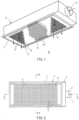
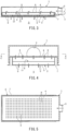
- FIGS. 1 to 5 show a pneumatic radiation unit according to Embodiment 1 of the present invention.
- the pneumatic radiation unit includes: a first chamber 1, through which air-conditioning air flows; and a second chamber 2 configured to take in the air-conditioning air from the first chamber 1 and discharge the air-conditioning air and radiate heat to a space S to be air conditioned, such as a room.
- bold dotted arrows each indicate a direction in which the air-conditioning air flows.
- the first chamber 1 includes: an air inlet 3, through which the air-conditioning air is taken in; and a flat plate-shaped first air discharger 4, which is in contact with the second chamber 2 and configured to discharge the air-conditioning air to the internal space of the second chamber 2.
- the second chamber 2 includes: a flat plate-shaped second air discharger 5, which is in contact with the space S to be air conditioned and configured to discharge the air-conditioning air to the space S to be air conditioned; a heat storage unit 6; and a flange-equipped frame member 7, to which the second air discharger 5 and the heat storage unit 6 are mounted.
- the pneumatic radiation unit is installed, for example, on the ceiling of the space S to be air conditioned, such that the second air discharger 5 faces the space S to be air conditioned.
- the air inlet 3 is connected to an air outlet of an unshown air conditioner via a duct 11, and the air-conditioning air is supplied from the air conditioner to the internal space of the first chamber 1.
- Each of the first chamber 1 and the second chamber 2 is formed to have a flattened shape, and the first chamber 1 and the second chamber 2 are adjacent to each other in a direction in which the first chamber 1 and the second chamber 2 are flattened (i.e., in the vertical direction in FIGS. 3 and 4 ).
- the first chamber 1 and the second chamber 2 are provided adjacently to each other, such that a main flat surface of the first chamber 1 having the flattened shape and a main flat surface of the second chamber 2 having the flattened shape are arranged at positions opposite to each other.
- each of the first chamber 1 and the second chamber 2 has a rectangular flattened shape.
- the shape of each of these chambers may be freely changed into any of various flattened shapes, such as a long and thin flattened shape, a square flattened shape, and a round flattened shape.
- the first air discharger 4 includes a large number of first through holes 8, through which the air-conditioning air is discharged from the first chamber 1 to the second chamber 2, such that the first air discharger 4 has a predetermined first aperture ratio.
- the second air discharger 5 includes a large number of second through holes 9, through which the air-conditioning air is discharged from the second chamber 2 to the space S to be air conditioned, such that the second air discharger 5 has a predetermined second aperture ratio.
- the second aperture ratio of the second air discharger 5 is set to be greater than the first aperture ratio of the first air discharger 4.
- aperture ratios are set such that, for example, the second aperture ratio of the second air discharger 5 is 70 to 80% and the first aperture ratio of the first air discharger 4 is 40 to 60%. Owing to such setting, the flow velocity of the air-conditioning air is gradually reduced by decreasing the dynamic pressure of the air-conditioning air and increasing the static pressure of the air-conditioning air in two stages.
- the shape of the first through holes 8 and the second through holes 9 may be freely selected from among various shapes, such as perfect circle, ellipse, elongated hole, thin slit, etc. Also, the number and dimensions of the through holes 8 and 9 may be freely selected.
- plates 10, which store and radiate the heat of the air-conditioning air are arranged to be spaced apart from each other such that gaps are formed between the plates 10, the gaps extending in a direction in which the air-conditioning air that has passed through the first through holes 8 of the first air discharger 4 flows.
- the plates 10 and the second air discharger 5 are made of, for example, aluminum whose thermal conductivity and thermal radiation rate are high.
- the air-conditioning air spreads out by being divided by the plates 10 into multiple flows that are also straightened by the plates 10, and then the flows of the air-conditioning air are discharged to the space S to be air conditioned through the second through holes 9 of the second air discharger 5.
- the heat of the air-conditioning air is thermally transferred to the plates 10 and the second air discharger 5, and then radiated from the second through holes 9 and the second air discharger 5 to the space S to be air conditioned.
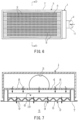
- FIGS. 6 and 7 show a pneumatic radiation unit according to one variation of Embodiment 1 of the present invention.
- the pneumatic radiation unit according to this variation is configured such that, in the second chamber 2 of the pneumatic radiation unit according to Embodiment 1, the second air discharger 5 including a large number of second through holes 9 is formed to have a corrugated shape. It should be noted that the inclination angle, the height, and the number of ridges and grooves of the corrugated shape may be freely selected. Since the other configuration features of the pneumatic radiation unit according to this variation are the same as those of the pneumatic radiation unit according to Embodiment 1 shown in FIG. 1 , the description thereof is omitted.
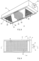
- FIGS. 8 to 12 show a pneumatic radiation unit according to Embodiment 2 of the present invention.
- the pneumatic radiation unit includes: a first chamber 21, through which air-conditioning air flows; and a second chamber 22 configured to take in the air-conditioning air from the first chamber 21 and discharge the air-conditioning air and radiate heat to a space S to be air conditioned, such as a room.
- bold dotted arrows each indicate a direction in which the air-conditioning air flows.
- the first chamber 21 includes: an air inlet 23, through which the air-conditioning air is taken in; and a flat plate-shaped first air discharger 24, which is in contact with the second chamber 22 and configured to discharge the air-conditioning air to the internal space of the second chamber 22.
- the second chamber 22 includes: a flat plate-shaped second air discharger 25, which is in contact with the space S to be air conditioned and configured to discharge the air-conditioning air to the space S to be air conditioned; a heat storage unit 26; and a flange-equipped frame member 27, to which the second air discharger 25 and the heat storage unit 26 are mounted.
- the pneumatic radiation unit is installed, for example, on the ceiling of the space S to be air conditioned, such that the second air discharger 25 faces the space S to be air conditioned.
- the air inlet 23 is connected to an air outlet of an unshown air conditioner via a duct 31, and the air-conditioning air is supplied from the air conditioner to the internal space of the first chamber 21.
- Each of the first chamber 21 and the second chamber 22 is formed to have a flattened shape, and the first chamber 21 and the second chamber 22 are adjacent to each other in a direction in which the first chamber 21 and the second chamber 22 are flattened (i.e., in the vertical direction in FIGS. 10 and 11 ).
- the first chamber 21 and the second chamber 22 are provided adjacently to each other, such that a main flat surface of the first chamber 21 having the flattened shape and a main flat surface of the second chamber 22 having the flattened shape are arranged at positions opposite to each other.
- each of the first chamber 21 and the second chamber 22 has a rectangular flattened shape.
- the shape of each of these chambers may be freely changed into any of various flattened shapes, such as a long and thin flattened shape, a square flattened shape, and a round flattened shape.
- the cross-sectional area of a flow passage of the air-conditioning air in the first chamber 21 (i.e., the cross-sectional area parallel to line B-B of FIG. 9 ) is set such that the cross-sectional area is gradually reduced from the upwind side to the downwind side of the flow passage of the air-conditioning air.
- both outer and inner surfaces of the first chamber 21 are sloped to reduce the cross-sectional area.
- only the inner surface may be sloped to reduce the cross-sectional area without sloping the outer surface.
- the first air discharger 24 includes first through holes 28, through which the air-conditioning air is discharged from the first chamber 21 to the second chamber 22. In the illustrated example, dividing portions between the first through holes 28 double as ribs, thereby increasing the stiffness of the first air discharger 24.
- the second air discharger 25 includes a large number of second through holes 29, through which the air-conditioning air is discharged from the second chamber 22 to the space S to be air conditioned, such that the second air discharger 25 has a predetermined second aperture ratio.
- the second aperture ratio of the second air discharger 25 is set to 70 to 80%, for example.
- the shape of the first through holes 28 and the second through holes 29 may be freely selected from among various shapes, such as perfect circle, ellipse, elongated hole, thin slit, etc. Also, the number and dimensions of the through holes 28 and 29 may be freely selected.
- plates 30, which store and radiate the heat of the air-conditioning air are arranged to be spaced apart from each other such that gaps are formed between the plates 30, the gaps extending in a direction in which the air-conditioning air that has passed through the first through holes 28 of the first air discharger 24 flows.
- the plates 30 and the second air discharger 25 are made of, for example, aluminum whose thermal conductivity and thermal radiation rate are high.
- the air-conditioning air spreads out by being divided by the plates 30 into multiple flows that are also straightened by the plates 30, and then the flows of the air-conditioning air are discharged to the space S to be air conditioned through the second through holes 29 of the second air discharger 25.
- the heat of the air-conditioning air is thermally transferred to the plates 30 and the second air discharger 25, and then radiated from the second through holes 29 and the second air discharger 25 to the space S to be air conditioned.
- FIGS. 13 and 14 show a pneumatic radiation unit according to one variation of Embodiment 2 of the present invention.
- the pneumatic radiation unit according to this variation is configured such that, in the second chamber 22 of the pneumatic radiation unit according to Embodiment 2, the second air discharger 25 including a large number of second through holes 29 is formed to have a corrugated shape. It should be noted that the inclination angle, the height, and the number of ridges and grooves of the corrugated shape may be freely selected. Since the other configuration features of the pneumatic radiation unit according to this variation are the same as those of the pneumatic radiation unit according to Embodiment 2 shown in FIG. 8 , the description thereof is omitted.
Landscapes
- Engineering & Computer Science (AREA)
- Chemical & Material Sciences (AREA)
- Combustion & Propulsion (AREA)
- Mechanical Engineering (AREA)
- General Engineering & Computer Science (AREA)
- Life Sciences & Earth Sciences (AREA)
- Sustainable Development (AREA)
- Physics & Mathematics (AREA)
- Thermal Sciences (AREA)
- Duct Arrangements (AREA)
- Air-Flow Control Members (AREA)
- Jet Pumps And Other Pumps (AREA)
Claims (4)
- Pneumatische Strahlungseinheit, umfassend:eine erste Kammer (1,21), durch die klimatisierte Luft strömt; undeine zweite Kammer (2, 22), die dazu konfiguriert ist, die klimatisierte Luft aus der ersten Kammer (1, 21) aufzunehmen und die klimatisierte Luft und Strahlungswärme in einen zu klimatisierenden Raum abzugeben, wobeidie erste Kammer (1, 21) einen ersten Luftausströmer (4, 24) beinhaltet, der mit der zweiten Kammer (2, 22) in Kontakt steht und dazu konfiguriert ist, die klimatisierte Luft in die zweite Kammer (2, 22) abzugeben,die zweite Kammer (2, 22) Folgendes beinhaltet:einen zweiten Luftausströmer (5, 25), der mit dem zu klimatisierenden Raum in Kontakt steht und dazu konfiguriert ist, die klimatisierte Luft in den zu klimatisierenden Raum abzugeben; gekennzeichnet durcheine Wärmespeichereinheit (6, 26), die Platten (10, 30) beinhaltet, die Wärme der klimatisierten Luft speichern und abstrahlen und die derart angeordnet sind, dass sie derart voneinander beabstandet sind, dass Spalte zwischen den Platten (10, 30) gebildet sind, wobei sich die Spalte in einer Richtung erstrecken, in der die klimatisierte Luft, die den ersten Luftausströmer (4, 24) passiert hat, strömt, undein zweites Öffnungsverhältnis des zweiten Luftausströmers (5, 25) auf 70 bis 80 % eingestellt ist und ein erstes Öffnungsverhältnis des ersten Luftausströmers (4, 24) auf 40 bis 60 % eingestellt ist.
- Pneumatische Strahlungseinheit nach Anspruch 1, wobeider erste Luftausströmer (4, 24) eine große Anzahl von ersten Durchgangslöchern (8, 28) beinhaltet, durch die die klimatisierte Luft aus der ersten Kammer (1, 21) in die zweite Kammer (2, 22) abgegeben wird, sodass der erste Luftausströmer (4, 24) das erste Öffnungsverhältnis von 40 bis 60 % aufweist, undder zweite Luftausströmer (5, 25) eine große Anzahl von zweiten Durchgangslöchern (9, 29) beinhaltet, durch die die klimatisierte Luft aus der zweiten Kammer (2, 22) in den zu klimatisierenden Raum abgegeben wird, sodass der zweite Luftausströmer (5, 25) das zweite Öffnungsverhältnis von 70 bis 80 % aufweist.
- Pneumatische Strahlungseinheit nach Anspruch 2, wobei
in der Wärmespeichereinheit (6, 26) die Platten (10, 30) derart angeordnet sind, dass sie derart voneinander beabstandet sind, dass Spalte zwischen den Platten (10, 30) gebildet werden, wobei sich die Spalte in einer Richtung erstrecken, in der die klimatisierte Luft, die die ersten Durchgangslöcher (8, 28) des ersten Luftausströmers (4, 24) passiert hat, strömt. - Pneumatische Strahlungseinheit nach Anspruch 2 oder 3, wobei
der zweite Luftausströmer (5, 25) der zweiten Kammer (2, 22) derart ausgebildet ist, dass er eine gewellte Form aufweist.
Applications Claiming Priority (2)
| Application Number | Priority Date | Filing Date | Title |
|---|---|---|---|
| JP2018044837A JP6600027B2 (ja) | 2018-03-13 | 2018-03-13 | 空気式放射ユニット |
| JP2018063924A JP6600030B2 (ja) | 2018-03-29 | 2018-03-29 | 空気式放射ユニット |
Publications (2)
| Publication Number | Publication Date |
|---|---|
| EP3540319A1 EP3540319A1 (de) | 2019-09-18 |
| EP3540319B1 true EP3540319B1 (de) | 2023-11-01 |
Family
ID=65717748
Family Applications (1)
| Application Number | Title | Priority Date | Filing Date |
|---|---|---|---|
| EP19160721.7A Active EP3540319B1 (de) | 2018-03-13 | 2019-03-05 | Pneumatische strahlungseinheit |
Country Status (6)
| Country | Link |
|---|---|
| US (1) | US11268705B2 (de) |
| EP (1) | EP3540319B1 (de) |
| CN (2) | CN110274327A (de) |
| AU (1) | AU2019201473B2 (de) |
| CA (1) | CA3035529C (de) |
| ES (1) | ES2969561T3 (de) |
Families Citing this family (8)
| Publication number | Priority date | Publication date | Assignee | Title |
|---|---|---|---|---|
| AU2019201473B2 (en) * | 2018-03-13 | 2020-10-29 | Kimura Kohki Co., Ltd. | Pneumatic radiation unit |
| JP2020041749A (ja) | 2018-09-11 | 2020-03-19 | 木村工機株式会社 | 空気式放射空調機 |
| AU2020267770B2 (en) | 2019-05-09 | 2023-12-21 | 80 Acres Urban Agriculture Inc. | Method and apparatus for high-density indoor farming |
| AU2020274162B2 (en) | 2019-05-13 | 2023-11-30 | 80 Acres Urban Agriculture, Inc. | System and method for controlling indoor farms remotely and user interface for same |
| CN111649387B (zh) * | 2020-05-28 | 2021-08-20 | 南京天加环境科技有限公司 | 一种空调末端空气调节装置 |
| CA3234529A1 (en) | 2021-10-20 | 2023-04-27 | Patricia C. Livingston | Automated indoor growing apparatuses and related methods |
| US20250043973A1 (en) * | 2023-08-01 | 2025-02-06 | Caplow Tech, LLC | Radiative cooling device |
| WO2025059181A1 (en) * | 2023-09-12 | 2025-03-20 | 80 Acres Urban Agriculture Inc. | Automated indoor growing apparatuses and related methods |
Family Cites Families (33)
| Publication number | Priority date | Publication date | Assignee | Title |
|---|---|---|---|---|
| US3033097A (en) * | 1959-09-08 | 1962-05-08 | Anemostat Corp America | Air distribution control outlet |
| US3246643A (en) * | 1964-03-31 | 1966-04-19 | Peerless Mfg Division Dover Co | Heating and ventilating system |
| US3308741A (en) * | 1965-05-28 | 1967-03-14 | Chambers John Edward | Ventilating air diffuser apparatus |
| US3824909A (en) * | 1970-04-08 | 1974-07-23 | Cgt Corp | Distribution system for clean rooms |
| GB1537783A (en) * | 1976-02-20 | 1979-01-04 | Prl Soc | Convector heater |
| SE7810734L (sv) * | 1978-10-13 | 1980-04-14 | Lind Leif Ingemar | Flodesfordelningsdon samt tilluftskerm forsedd med sadant don |
| SE443442B (sv) * | 1981-09-30 | 1986-02-24 | Leif Ingemar Lind | Flodesfordelningsdon |
| SE445069C (sv) * | 1983-12-05 | 1991-10-07 | Stifab Ab | Tilluftsdon |
| DE3605539A1 (de) * | 1986-02-18 | 1987-08-20 | Herbst Donald | Vorrichtung zum zufuehren eines luftstroms in einen raum |
| US4825603A (en) * | 1987-03-23 | 1989-05-02 | Farley, Inc. | Elevated floor plate |
| SE8704133L (sv) * | 1987-10-22 | 1989-04-23 | Flaekt Ab | Luftdistributionsdon |
| SE504421C2 (sv) * | 1990-03-29 | 1997-02-03 | Mats Kronfaelt | Tilluftsdon där tilluft valbart kan tillföras lokal genom ett högimpulsdon alternativt ett låghastighetsdon |
| CA2071680C (en) * | 1992-06-19 | 1998-05-05 | Walter D. Klassen | Radial flow diffuser |
| JP3746120B2 (ja) * | 1996-11-20 | 2006-02-15 | 三機工業株式会社 | クリーンルーム用空気吹出装置 |
| US6264551B1 (en) * | 2000-09-08 | 2001-07-24 | Randall L. Smith | Concentric air diffuser |
| FR2824626B1 (fr) * | 2001-05-14 | 2004-04-16 | Pierre Bridenne | Procede et dispositif pour diffuser un flux de protection a l'egard d'une ambiance environnante |
| DE10144755A1 (de) * | 2001-09-11 | 2003-03-27 | Utescheny Ag | Luftleitvorrichtung |
| DE10160464C1 (de) * | 2001-12-10 | 2003-08-21 | Schako Metallwarenfabrik | Quellauslass |
| CN100535532C (zh) * | 2003-02-20 | 2009-09-02 | 大金工业株式会社 | 辐射面板结构体和空调机 |
| JP2007155205A (ja) | 2005-12-05 | 2007-06-21 | Nippon Spindle Mfg Co Ltd | クリーンブース |
| US7597617B2 (en) * | 2007-03-02 | 2009-10-06 | Andrew Solberg | Gas diffusion device |
| JP4792101B2 (ja) * | 2009-06-09 | 2011-10-12 | 木村工機株式会社 | 空気式輻射層流ユニット |
| AU2010201383B9 (en) * | 2009-04-13 | 2011-06-02 | Kimura Kohki Co., Ltd. | Heating and cooling unit, and heating and cooling apparatus |
| JP2011149677A (ja) * | 2010-01-22 | 2011-08-04 | Inter Central:Kk | 全空気方式天井冷暖房システム |
| JP5043158B2 (ja) * | 2010-06-23 | 2012-10-10 | 木村工機株式会社 | 空気熱源ヒートポンプ式空調装置 |
| WO2013082647A1 (en) * | 2011-12-05 | 2013-06-13 | Kaip Pty Limited | An air diffuser and an air circulation system |
| US8511022B2 (en) * | 2012-01-20 | 2013-08-20 | Tate Access Floors Leasing, Inc. | Access floor panel having intermingled directional and non-directional air passageways |
| CN103968515A (zh) | 2013-02-01 | 2014-08-06 | 展烨有限公司 | 空调设备出风口 |
| CN104235974A (zh) * | 2013-06-14 | 2014-12-24 | 无锡市河埒空调设备有限公司 | 一种新型湿帘节能纺织空调系统 |
| CN104748456A (zh) * | 2013-12-25 | 2015-07-01 | 珠海格力电器股份有限公司 | 空调系统 |
| SE540686C2 (sv) * | 2014-10-23 | 2018-10-09 | Qleanair Scandinavia Ab | Dragrum med perforeringsfördelning |
| JP6335419B2 (ja) * | 2016-08-26 | 2018-05-30 | 木村工機株式会社 | 空気式誘引放射ユニット |
| AU2019201473B2 (en) * | 2018-03-13 | 2020-10-29 | Kimura Kohki Co., Ltd. | Pneumatic radiation unit |
-
2019
- 2019-03-04 AU AU2019201473A patent/AU2019201473B2/en active Active
- 2019-03-04 CA CA3035529A patent/CA3035529C/en active Active
- 2019-03-05 ES ES19160721T patent/ES2969561T3/es active Active
- 2019-03-05 EP EP19160721.7A patent/EP3540319B1/de active Active
- 2019-03-12 US US16/299,608 patent/US11268705B2/en active Active
- 2019-03-13 CN CN201910190223.1A patent/CN110274327A/zh active Pending
- 2019-03-13 CN CN201920317346.2U patent/CN209726402U/zh not_active Expired - Fee Related
Also Published As
| Publication number | Publication date |
|---|---|
| CA3035529A1 (en) | 2019-09-13 |
| EP3540319A1 (de) | 2019-09-18 |
| US20190285287A1 (en) | 2019-09-19 |
| US11268705B2 (en) | 2022-03-08 |
| AU2019201473B2 (en) | 2020-10-29 |
| ES2969561T3 (es) | 2024-05-21 |
| CN110274327A (zh) | 2019-09-24 |
| CN209726402U (zh) | 2019-12-03 |
| AU2019201473A1 (en) | 2019-10-03 |
| CA3035529C (en) | 2021-01-19 |
Similar Documents
| Publication | Publication Date | Title |
|---|---|---|
| US11268705B2 (en) | Pneumatic radiation unit | |
| US9291407B2 (en) | Multi-channel heat exchanger with improved uniformity of refrigerant fluid distribution | |
| JP4999941B2 (ja) | 空気式誘引放射ユニット | |
| US10168083B2 (en) | Refrigeration system and heat exchanger thereof | |
| US20130199288A1 (en) | Fluid flow distribution device | |
| JP2014084107A (ja) | 車両用帯状通気システム | |
| CN106322842A (zh) | 一种微通道换热器及其在系统中的应用 | |
| CA3052746C (en) | Pneumatic radiation air conditioner | |
| US20220034593A1 (en) | Heat exchanger devices and systems and associated methods | |
| JP2017172935A (ja) | 空気調和機 | |
| CN212320029U (zh) | 导风板、空调室内机和空调器 | |
| CN211290288U (zh) | 空气调节装置 | |
| CN114061133A (zh) | 导风板、空调室内机和空调器 | |
| JP6600027B2 (ja) | 空気式放射ユニット | |
| EP3394520A1 (de) | Verfahren zur luftverteilung und -aufnahme und system dafür | |
| JP6600030B2 (ja) | 空気式放射ユニット | |
| US20240369312A1 (en) | Parallel plate support elements | |
| CN114396648A (zh) | 定点送风系统 | |
| CN110006158A (zh) | 空调出风装置和空调器 | |
| CN107490064B (zh) | 室内机和空调系统 | |
| JP2026052050A (ja) | 吹出口装置 | |
| CN201522230U (zh) | 分配管和具有该分配管的换热器 | |
| WO2021000502A1 (zh) | 空气调节装置 | |
| HK1156388B (en) | Air-type radiation guiding unit | |
| JPH0217388A (ja) | 流動層熱交換器 |
Legal Events
| Date | Code | Title | Description |
|---|---|---|---|
| PUAI | Public reference made under article 153(3) epc to a published international application that has entered the european phase |
Free format text: ORIGINAL CODE: 0009012 |
|
| STAA | Information on the status of an ep patent application or granted ep patent |
Free format text: STATUS: REQUEST FOR EXAMINATION WAS MADE |
|
| 17P | Request for examination filed |
Effective date: 20190305 |
|
| AK | Designated contracting states |
Kind code of ref document: A1 Designated state(s): AL AT BE BG CH CY CZ DE DK EE ES FI FR GB GR HR HU IE IS IT LI LT LU LV MC MK MT NL NO PL PT RO RS SE SI SK SM TR |
|
| AX | Request for extension of the european patent |
Extension state: BA ME |
|
| STAA | Information on the status of an ep patent application or granted ep patent |
Free format text: STATUS: EXAMINATION IS IN PROGRESS |
|
| 17Q | First examination report despatched |
Effective date: 20220726 |
|
| GRAP | Despatch of communication of intention to grant a patent |
Free format text: ORIGINAL CODE: EPIDOSNIGR1 |
|
| STAA | Information on the status of an ep patent application or granted ep patent |
Free format text: STATUS: GRANT OF PATENT IS INTENDED |
|
| GRAJ | Information related to disapproval of communication of intention to grant by the applicant or resumption of examination proceedings by the epo deleted |
Free format text: ORIGINAL CODE: EPIDOSDIGR1 |
|
| GRAP | Despatch of communication of intention to grant a patent |
Free format text: ORIGINAL CODE: EPIDOSNIGR1 |
|
| INTG | Intention to grant announced |
Effective date: 20230607 |
|
| INTG | Intention to grant announced |
Effective date: 20230607 |
|
| RIN1 | Information on inventor provided before grant (corrected) |
Inventor name: URANO, KATSUHIRO Inventor name: KIMURA, KEIICHI |
|
| RIN1 | Information on inventor provided before grant (corrected) |
Inventor name: URANO, KATSUHIRO Inventor name: KIMURA, KEIICHI |
|
| GRAS | Grant fee paid |
Free format text: ORIGINAL CODE: EPIDOSNIGR3 |
|
| GRAA | (expected) grant |
Free format text: ORIGINAL CODE: 0009210 |
|
| STAA | Information on the status of an ep patent application or granted ep patent |
Free format text: STATUS: THE PATENT HAS BEEN GRANTED |
|
| AK | Designated contracting states |
Kind code of ref document: B1 Designated state(s): AL AT BE BG CH CY CZ DE DK EE ES FI FR GB GR HR HU IE IS IT LI LT LU LV MC MK MT NL NO PL PT RO RS SE SI SK SM TR |
|
| REG | Reference to a national code |
Ref country code: GB Ref legal event code: FG4D |
|
| REG | Reference to a national code |
Ref country code: CH Ref legal event code: EP |
|
| REG | Reference to a national code |
Ref country code: DE Ref legal event code: R096 Ref document number: 602019040402 Country of ref document: DE |
|
| REG | Reference to a national code |
Ref country code: IE Ref legal event code: FG4D |
|
| REG | Reference to a national code |
Ref country code: LT Ref legal event code: MG9D |
|
| REG | Reference to a national code |
Ref country code: NL Ref legal event code: MP Effective date: 20231101 |
|
| PG25 | Lapsed in a contracting state [announced via postgrant information from national office to epo] |
Ref country code: GR Free format text: LAPSE BECAUSE OF FAILURE TO SUBMIT A TRANSLATION OF THE DESCRIPTION OR TO PAY THE FEE WITHIN THE PRESCRIBED TIME-LIMIT Effective date: 20240202 |
|
| PG25 | Lapsed in a contracting state [announced via postgrant information from national office to epo] |
Ref country code: IS Free format text: LAPSE BECAUSE OF FAILURE TO SUBMIT A TRANSLATION OF THE DESCRIPTION OR TO PAY THE FEE WITHIN THE PRESCRIBED TIME-LIMIT Effective date: 20240301 |
|
| PG25 | Lapsed in a contracting state [announced via postgrant information from national office to epo] |
Ref country code: LT Free format text: LAPSE BECAUSE OF FAILURE TO SUBMIT A TRANSLATION OF THE DESCRIPTION OR TO PAY THE FEE WITHIN THE PRESCRIBED TIME-LIMIT Effective date: 20231101 |
|
| REG | Reference to a national code |
Ref country code: AT Ref legal event code: MK05 Ref document number: 1627616 Country of ref document: AT Kind code of ref document: T Effective date: 20231101 |
|
| PG25 | Lapsed in a contracting state [announced via postgrant information from national office to epo] |
Ref country code: NL Free format text: LAPSE BECAUSE OF FAILURE TO SUBMIT A TRANSLATION OF THE DESCRIPTION OR TO PAY THE FEE WITHIN THE PRESCRIBED TIME-LIMIT Effective date: 20231101 |
|
| PG25 | Lapsed in a contracting state [announced via postgrant information from national office to epo] |
Ref country code: AT Free format text: LAPSE BECAUSE OF FAILURE TO SUBMIT A TRANSLATION OF THE DESCRIPTION OR TO PAY THE FEE WITHIN THE PRESCRIBED TIME-LIMIT Effective date: 20231101 |
|
| PG25 | Lapsed in a contracting state [announced via postgrant information from national office to epo] |
Ref country code: NL Free format text: LAPSE BECAUSE OF FAILURE TO SUBMIT A TRANSLATION OF THE DESCRIPTION OR TO PAY THE FEE WITHIN THE PRESCRIBED TIME-LIMIT Effective date: 20231101 Ref country code: LT Free format text: LAPSE BECAUSE OF FAILURE TO SUBMIT A TRANSLATION OF THE DESCRIPTION OR TO PAY THE FEE WITHIN THE PRESCRIBED TIME-LIMIT Effective date: 20231101 Ref country code: IS Free format text: LAPSE BECAUSE OF FAILURE TO SUBMIT A TRANSLATION OF THE DESCRIPTION OR TO PAY THE FEE WITHIN THE PRESCRIBED TIME-LIMIT Effective date: 20240301 Ref country code: GR Free format text: LAPSE BECAUSE OF FAILURE TO SUBMIT A TRANSLATION OF THE DESCRIPTION OR TO PAY THE FEE WITHIN THE PRESCRIBED TIME-LIMIT Effective date: 20240202 Ref country code: BG Free format text: LAPSE BECAUSE OF FAILURE TO SUBMIT A TRANSLATION OF THE DESCRIPTION OR TO PAY THE FEE WITHIN THE PRESCRIBED TIME-LIMIT Effective date: 20240201 Ref country code: AT Free format text: LAPSE BECAUSE OF FAILURE TO SUBMIT A TRANSLATION OF THE DESCRIPTION OR TO PAY THE FEE WITHIN THE PRESCRIBED TIME-LIMIT Effective date: 20231101 Ref country code: PT Free format text: LAPSE BECAUSE OF FAILURE TO SUBMIT A TRANSLATION OF THE DESCRIPTION OR TO PAY THE FEE WITHIN THE PRESCRIBED TIME-LIMIT Effective date: 20240301 |
|
| REG | Reference to a national code |
Ref country code: ES Ref legal event code: FG2A Ref document number: 2969561 Country of ref document: ES Kind code of ref document: T3 Effective date: 20240521 |
|
| PG25 | Lapsed in a contracting state [announced via postgrant information from national office to epo] |
Ref country code: SE Free format text: LAPSE BECAUSE OF FAILURE TO SUBMIT A TRANSLATION OF THE DESCRIPTION OR TO PAY THE FEE WITHIN THE PRESCRIBED TIME-LIMIT Effective date: 20231101 Ref country code: RS Free format text: LAPSE BECAUSE OF FAILURE TO SUBMIT A TRANSLATION OF THE DESCRIPTION OR TO PAY THE FEE WITHIN THE PRESCRIBED TIME-LIMIT Effective date: 20231101 Ref country code: PL Free format text: LAPSE BECAUSE OF FAILURE TO SUBMIT A TRANSLATION OF THE DESCRIPTION OR TO PAY THE FEE WITHIN THE PRESCRIBED TIME-LIMIT Effective date: 20231101 Ref country code: NO Free format text: LAPSE BECAUSE OF FAILURE TO SUBMIT A TRANSLATION OF THE DESCRIPTION OR TO PAY THE FEE WITHIN THE PRESCRIBED TIME-LIMIT Effective date: 20240201 Ref country code: LV Free format text: LAPSE BECAUSE OF FAILURE TO SUBMIT A TRANSLATION OF THE DESCRIPTION OR TO PAY THE FEE WITHIN THE PRESCRIBED TIME-LIMIT Effective date: 20231101 Ref country code: HR Free format text: LAPSE BECAUSE OF FAILURE TO SUBMIT A TRANSLATION OF THE DESCRIPTION OR TO PAY THE FEE WITHIN THE PRESCRIBED TIME-LIMIT Effective date: 20231101 |
|
| PG25 | Lapsed in a contracting state [announced via postgrant information from national office to epo] |
Ref country code: DK Free format text: LAPSE BECAUSE OF FAILURE TO SUBMIT A TRANSLATION OF THE DESCRIPTION OR TO PAY THE FEE WITHIN THE PRESCRIBED TIME-LIMIT Effective date: 20231101 |
|
| PG25 | Lapsed in a contracting state [announced via postgrant information from national office to epo] |
Ref country code: CZ Free format text: LAPSE BECAUSE OF FAILURE TO SUBMIT A TRANSLATION OF THE DESCRIPTION OR TO PAY THE FEE WITHIN THE PRESCRIBED TIME-LIMIT Effective date: 20231101 |
|
| PG25 | Lapsed in a contracting state [announced via postgrant information from national office to epo] |
Ref country code: SK Free format text: LAPSE BECAUSE OF FAILURE TO SUBMIT A TRANSLATION OF THE DESCRIPTION OR TO PAY THE FEE WITHIN THE PRESCRIBED TIME-LIMIT Effective date: 20231101 |
|
| PG25 | Lapsed in a contracting state [announced via postgrant information from national office to epo] |
Ref country code: SM Free format text: LAPSE BECAUSE OF FAILURE TO SUBMIT A TRANSLATION OF THE DESCRIPTION OR TO PAY THE FEE WITHIN THE PRESCRIBED TIME-LIMIT Effective date: 20231101 Ref country code: SK Free format text: LAPSE BECAUSE OF FAILURE TO SUBMIT A TRANSLATION OF THE DESCRIPTION OR TO PAY THE FEE WITHIN THE PRESCRIBED TIME-LIMIT Effective date: 20231101 Ref country code: EE Free format text: LAPSE BECAUSE OF FAILURE TO SUBMIT A TRANSLATION OF THE DESCRIPTION OR TO PAY THE FEE WITHIN THE PRESCRIBED TIME-LIMIT Effective date: 20231101 Ref country code: DK Free format text: LAPSE BECAUSE OF FAILURE TO SUBMIT A TRANSLATION OF THE DESCRIPTION OR TO PAY THE FEE WITHIN THE PRESCRIBED TIME-LIMIT Effective date: 20231101 Ref country code: CZ Free format text: LAPSE BECAUSE OF FAILURE TO SUBMIT A TRANSLATION OF THE DESCRIPTION OR TO PAY THE FEE WITHIN THE PRESCRIBED TIME-LIMIT Effective date: 20231101 |
|
| REG | Reference to a national code |
Ref country code: DE Ref legal event code: R097 Ref document number: 602019040402 Country of ref document: DE |
|
| PLBE | No opposition filed within time limit |
Free format text: ORIGINAL CODE: 0009261 |
|
| STAA | Information on the status of an ep patent application or granted ep patent |
Free format text: STATUS: NO OPPOSITION FILED WITHIN TIME LIMIT |
|
| 26N | No opposition filed |
Effective date: 20240802 |
|
| PG25 | Lapsed in a contracting state [announced via postgrant information from national office to epo] |
Ref country code: SI Free format text: LAPSE BECAUSE OF FAILURE TO SUBMIT A TRANSLATION OF THE DESCRIPTION OR TO PAY THE FEE WITHIN THE PRESCRIBED TIME-LIMIT Effective date: 20231101 |
|
| PG25 | Lapsed in a contracting state [announced via postgrant information from national office to epo] |
Ref country code: SI Free format text: LAPSE BECAUSE OF FAILURE TO SUBMIT A TRANSLATION OF THE DESCRIPTION OR TO PAY THE FEE WITHIN THE PRESCRIBED TIME-LIMIT Effective date: 20231101 |
|
| REG | Reference to a national code |
Ref country code: CH Ref legal event code: PL |
|
| PG25 | Lapsed in a contracting state [announced via postgrant information from national office to epo] |
Ref country code: LU Free format text: LAPSE BECAUSE OF NON-PAYMENT OF DUE FEES Effective date: 20240305 |
|
| PG25 | Lapsed in a contracting state [announced via postgrant information from national office to epo] |
Ref country code: MC Free format text: LAPSE BECAUSE OF FAILURE TO SUBMIT A TRANSLATION OF THE DESCRIPTION OR TO PAY THE FEE WITHIN THE PRESCRIBED TIME-LIMIT Effective date: 20231101 |
|
| PG25 | Lapsed in a contracting state [announced via postgrant information from national office to epo] |
Ref country code: MC Free format text: LAPSE BECAUSE OF FAILURE TO SUBMIT A TRANSLATION OF THE DESCRIPTION OR TO PAY THE FEE WITHIN THE PRESCRIBED TIME-LIMIT Effective date: 20231101 Ref country code: LU Free format text: LAPSE BECAUSE OF NON-PAYMENT OF DUE FEES Effective date: 20240305 |
|
| REG | Reference to a national code |
Ref country code: BE Ref legal event code: MM Effective date: 20240331 |
|
| PG25 | Lapsed in a contracting state [announced via postgrant information from national office to epo] |
Ref country code: BE Free format text: LAPSE BECAUSE OF NON-PAYMENT OF DUE FEES Effective date: 20240331 |
|
| PG25 | Lapsed in a contracting state [announced via postgrant information from national office to epo] |
Ref country code: IE Free format text: LAPSE BECAUSE OF NON-PAYMENT OF DUE FEES Effective date: 20240305 |
|
| PG25 | Lapsed in a contracting state [announced via postgrant information from national office to epo] |
Ref country code: IE Free format text: LAPSE BECAUSE OF NON-PAYMENT OF DUE FEES Effective date: 20240305 Ref country code: BE Free format text: LAPSE BECAUSE OF NON-PAYMENT OF DUE FEES Effective date: 20240331 Ref country code: CH Free format text: LAPSE BECAUSE OF NON-PAYMENT OF DUE FEES Effective date: 20240331 |
|
| PGFP | Annual fee paid to national office [announced via postgrant information from national office to epo] |
Ref country code: ES Payment date: 20250416 Year of fee payment: 7 |
|
| PGFP | Annual fee paid to national office [announced via postgrant information from national office to epo] |
Ref country code: IT Payment date: 20250331 Year of fee payment: 7 |
|
| PG25 | Lapsed in a contracting state [announced via postgrant information from national office to epo] |
Ref country code: RO Free format text: LAPSE BECAUSE OF FAILURE TO SUBMIT A TRANSLATION OF THE DESCRIPTION OR TO PAY THE FEE WITHIN THE PRESCRIBED TIME-LIMIT Effective date: 20231101 |
|
| PG25 | Lapsed in a contracting state [announced via postgrant information from national office to epo] |
Ref country code: CY Free format text: LAPSE BECAUSE OF FAILURE TO SUBMIT A TRANSLATION OF THE DESCRIPTION OR TO PAY THE FEE WITHIN THE PRESCRIBED TIME-LIMIT; INVALID AB INITIO Effective date: 20190305 |
|
| PG25 | Lapsed in a contracting state [announced via postgrant information from national office to epo] |
Ref country code: HU Free format text: LAPSE BECAUSE OF FAILURE TO SUBMIT A TRANSLATION OF THE DESCRIPTION OR TO PAY THE FEE WITHIN THE PRESCRIBED TIME-LIMIT; INVALID AB INITIO Effective date: 20190305 |
|
| PG25 | Lapsed in a contracting state [announced via postgrant information from national office to epo] |
Ref country code: FI Free format text: LAPSE BECAUSE OF FAILURE TO SUBMIT A TRANSLATION OF THE DESCRIPTION OR TO PAY THE FEE WITHIN THE PRESCRIBED TIME-LIMIT Effective date: 20231101 |
|
| PG25 | Lapsed in a contracting state [announced via postgrant information from national office to epo] |
Ref country code: TR Free format text: LAPSE BECAUSE OF FAILURE TO SUBMIT A TRANSLATION OF THE DESCRIPTION OR TO PAY THE FEE WITHIN THE PRESCRIBED TIME-LIMIT Effective date: 20231101 |
|
| PGFP | Annual fee paid to national office [announced via postgrant information from national office to epo] |
Ref country code: GB Payment date: 20260218 Year of fee payment: 8 |
|
| PGFP | Annual fee paid to national office [announced via postgrant information from national office to epo] |
Ref country code: DE Payment date: 20260218 Year of fee payment: 8 |
|
| PGFP | Annual fee paid to national office [announced via postgrant information from national office to epo] |
Ref country code: FR Payment date: 20260218 Year of fee payment: 8 |