EP3540308B1 - Assembly and method for making a lamp incorporated in a wall or wall caldding - Google Patents
Assembly and method for making a lamp incorporated in a wall or wall caldding Download PDFInfo
- Publication number
- EP3540308B1 EP3540308B1 EP18212763.9A EP18212763A EP3540308B1 EP 3540308 B1 EP3540308 B1 EP 3540308B1 EP 18212763 A EP18212763 A EP 18212763A EP 3540308 B1 EP3540308 B1 EP 3540308B1
- Authority
- EP
- European Patent Office
- Prior art keywords
- wall
- assembly
- lamp
- blocks
- opening
- Prior art date
- Legal status (The legal status is an assumption and is not a legal conclusion. Google has not performed a legal analysis and makes no representation as to the accuracy of the status listed.)
- Active
Links
- 238000000034 method Methods 0.000 title claims description 13
- 239000004793 Polystyrene Substances 0.000 claims description 19
- 229920002223 polystyrene Polymers 0.000 claims description 19
- 238000005253 cladding Methods 0.000 claims description 15
- 239000011470 perforated brick Substances 0.000 claims description 14
- 238000009413 insulation Methods 0.000 claims description 12
- 239000011449 brick Substances 0.000 claims description 8
- 239000004568 cement Substances 0.000 claims description 7
- 238000010168 coupling process Methods 0.000 claims description 4
- 238000005859 coupling reaction Methods 0.000 claims description 4
- 239000007769 metal material Substances 0.000 claims description 2
- 238000004873 anchoring Methods 0.000 claims 1
- 238000009415 formwork Methods 0.000 description 3
- 230000001681 protective effect Effects 0.000 description 3
- 239000011358 absorbing material Substances 0.000 description 2
- 238000005266 casting Methods 0.000 description 2
- 230000008878 coupling Effects 0.000 description 2
- 230000000694 effects Effects 0.000 description 2
- 239000000463 material Substances 0.000 description 2
- 230000003287 optical effect Effects 0.000 description 2
- 239000011505 plaster Substances 0.000 description 2
- 229910000831 Steel Inorganic materials 0.000 description 1
- 230000006978 adaptation Effects 0.000 description 1
- 239000011248 coating agent Substances 0.000 description 1
- 238000000576 coating method Methods 0.000 description 1
- 230000000295 complement effect Effects 0.000 description 1
- 238000010276 construction Methods 0.000 description 1
- 230000001419 dependent effect Effects 0.000 description 1
- 238000009434 installation Methods 0.000 description 1
- 238000012986 modification Methods 0.000 description 1
- 230000004048 modification Effects 0.000 description 1
- 239000011150 reinforced concrete Substances 0.000 description 1
- 239000010959 steel Substances 0.000 description 1
- 238000006467 substitution reaction Methods 0.000 description 1
Images


Classifications
-
- F—MECHANICAL ENGINEERING; LIGHTING; HEATING; WEAPONS; BLASTING
- F21—LIGHTING
- F21S—NON-PORTABLE LIGHTING DEVICES; SYSTEMS THEREOF; VEHICLE LIGHTING DEVICES SPECIALLY ADAPTED FOR VEHICLE EXTERIORS
- F21S8/00—Lighting devices intended for fixed installation
- F21S8/02—Lighting devices intended for fixed installation of recess-mounted type, e.g. downlighters
- F21S8/024—Lighting devices intended for fixed installation of recess-mounted type, e.g. downlighters intended to be recessed in a wall or like vertical structure, e.g. building facade
-
- F—MECHANICAL ENGINEERING; LIGHTING; HEATING; WEAPONS; BLASTING
- F21—LIGHTING
- F21V—FUNCTIONAL FEATURES OR DETAILS OF LIGHTING DEVICES OR SYSTEMS THEREOF; STRUCTURAL COMBINATIONS OF LIGHTING DEVICES WITH OTHER ARTICLES, NOT OTHERWISE PROVIDED FOR
- F21V33/00—Structural combinations of lighting devices with other articles, not otherwise provided for
- F21V33/006—General building constructions or finishing work for buildings, e.g. roofs, gutters, stairs or floors; Garden equipment; Sunshades or parasols
-
- F—MECHANICAL ENGINEERING; LIGHTING; HEATING; WEAPONS; BLASTING
- F21—LIGHTING
- F21Y—INDEXING SCHEME ASSOCIATED WITH SUBCLASSES F21K, F21L, F21S and F21V, RELATING TO THE FORM OR THE KIND OF THE LIGHT SOURCES OR OF THE COLOUR OF THE LIGHT EMITTED
- F21Y2115/00—Light-generating elements of semiconductor light sources
- F21Y2115/10—Light-emitting diodes [LED]
Definitions
- the present invention concerns an assembly and a method for making a lamp incorporated in a wall or in a wall cladding, in particular in a polystyrene insulation wall cladding, or in a wall made of perforated bricks or blocks of other heat-insulating and/or sound-absorbing materials.
- Recessed lamps are already well known, i.e. those having the housing that houses the light source placed in a seat obtained in a wall or extending inside a cavity made from a plasterboard panel.
- a gap is usually made in the wall and, after positioning the lamp, the wall is restored, taking care to connect the visible surface of the wall to the edge of the lamp that delimits the emission opening of the light beam.
- an assembly and a method for making a lamp incorporated in a masonry wall for example a load-bearing wall made of reinforced concrete
- Such an assembly comprises a lamp housing which delimits a lamp seat suitable for housing a lamp body and which is intended to be incorporated within the masonry wall, and a mold suitable to be removably fixed to the lamp housing and having a front opening suitable to be placed in contact with the inner side of a formwork.
- the mold After casting the cement into the formwork, the mold forms a light emission cavity, which is suitable to rigidly support the lamp housing before and during casting of the cement and is provided with mold fixing means suitable to removably fix the mold to the inner side of the formwork.
- the document CN 2 837 671 Y shows a kind of lamp incorporated in a wall of perforated bricks.
- the object of the present invention is to propose an assembly and a method for obtaining a lamp inside a wall made of perforated bricks, blocks of another material or in an outer coating of the wall, in particular an insulation layer made of polystyrene panels.
- Another object of the invention is to propose an assembly and a method that allow even a non-specialized operator, such as the mason himself, to incorporate a lamp into a wall cladding, such as an insulation layer, quickly, safely and, at the same time, very precisely.
- ⁇ front' and 'rear' are used to refer to the wall, or a wall cladding thereof, which has a front side, facing outwards, and a rear side, opposite to the front side.
- Figures 1-4 illustrate an assembly 1 to make a lamp incorporated in an insulation layer 2 of a wall cladding 3, consisting of polystyrene panels 4.
- the assembly 1 comprises a front body 10 wherein a light emission cavity 12 is obtained.
- the light emission cavity 12 extends from a rear body opening 14 to a front body opening 16.
- the light emission cavity 12 is delimited by a substantially flat top wall 12' and a lower wall 12" inclined so that the light is emitted from the cavity 12 illuminating such inclined lower wall 12".
- the front body 10 forms a substantially flat front surface 102 extending around the front body opening 16.
- the front body 10 forms two side walls 104 that define the thickness of the front body 10.
- the assembly 1 comprises a lamp housing 18 which forms internally a lamp seat 182 suitable to house a lamp body 8 ( figure 3b ).
- the lamp housing 18 delimits a rear housing opening 184 for the passage of the power supply cables of the lamp body and a front housing opening 186, for the emission of the light beam generated by the lamp body 8.
- the front housing opening 186 is closed by an optical element 82.
- the rear housing opening 184 is suitable for the passage of a corrugated tube 19 that carries the power cables.
- the front housing opening 186 is suitable to face or be partially inserted into the rear body opening 14.
- the assembly 1 further comprises a rear body 20 forming a housing seat 22 suitable to receive with shape-coupling the lamp housing 18 protruding from the rear of the front body 10.
- the rear body 20 is suitable to be coupled to the front body 10 so as to form a monobloc panel 30 substantially parallelepiped in shape which completely incorporates the lamp housing 18.
- This monobloc panel 30 is suitable to be inserted and fixed in a corresponding volume formed between panels or blocks that form the cladding of the wall.
- the front surface 102 is suitable to receive a finishing layer 5 of the wall cladding.
- the monobloc panel 30 has at least the same thickness, preferably the same dimensions, as the polystyrene panels 4 and is used to replace one of these panels, as shown in figure 4 .
- the front 10 and rear 20 bodies are also made of polystyrene, so that the assembly 1, in addition to obtaining the lamp incorporated in the insulation, also performs the function of thermal insulation like the other panels 4.
- pre-cut incisions 32 are made, which may be used to resize the front body 10 according to the dimensions of the polystyrene panels between which the monobloc panel 30 is to be inserted.
- reference marks 34 are made for the application of bolts 35 for fastening the monobloc panel 30 to the wall 3.
- the reference marks 34 are positioned in such a way that the bolts pass through the monobloc panel 30 in areas where the optical, electrical and mechanical elements of the assembly 1 are not present.
- the rear body 20 is equipped with coupling pins 36 that fit into corresponding coupling holes made in a rear wall of the front body 10.
- the front body 10 forms, in an upper portion thereof, a rear cutout 38 that is filled by the rear body 20.
- such rear cutout 38 is delimited below by an inclined support wall 40 wherein the light emission cavity 12 leads, forming the rear body opening 14.
- the rear body 20 has a lower wall 202 inclined to complement the inclined support wall 40 and suitable to rest on such inclined support wall 40.
- one or more recesses 204, 206 for example in the vertical and/or lateral direction, for passing and guiding the power cables, preferably inserted in the corrugated tube 19.
- the lamp housing 18 is provided, in a front portion thereof, with a perimeter flange 188 adapted to abut against the inclined support wall 40 of the front body 10, which delimits the rear body opening 14.
- annular plate 42 made of metallic material, for example steel.
- the annular plate 42 serves as a reference and protection for supporting the lamp housing 18. While assembling the assembly 1, in effect, if the lamp housing 18 is pressed too hard against the inclined support wall 40, the latter could yield, compromising the perfect alignment between the lamp body 8 and the light emission cavity 12.
- the front body opening 16 is delimited by an opening edge 44 protruding relative to the front surface 102 which receives the finishing layer 5.
- the height of this opening edge 44 is substantially equal to the thickness of the finishing layer 5 so that the front opening 16 lies in an opening plane coplanar to the outer surface of the finishing layer 5.
- This contrivance allows the desired effect of perfect coplanarity to be obtained between the outer surface of the finishing layer 5 and the edge that delimits the front body opening 16, highlighted on the left side of figures 4 , 8 and 9 , even in the case of a finishing layer of a certain thickness, such as for example in the case of plaster.
- the opening edge 44 is connected to the front surface 102 by means of an inclined joining surface 46 wherein it is also possible to obtain a Greek key corrugated pattern 48 for adhering to the finishing layer 5.
- Figures 5, 6 and 7 show an assembly 100 that is particularly suitable for use in a perforated brick wall 104 ( figure 8 ) or in blocks 106 made of a heat-insulating and/or sound-absorbing material, for example the cement-based material marketed under the name of Leca®.
- the assembly 100 differs from the assembly 1 described above in that, in the side parts 104 of the front body 10, grooves 108 are made suitable to facilitate the connection with the adjacent bricks or blocks by means of cement.
- object of the invention is a method for incorporating a lamp into a wall, or wall cladding, with panels 4, perforated bricks 104 or blocks 106, using an assembly 1, 100 as described above.
- the method provides for laying the cladding panels on the wall or making the wall out of perforated bricks or blocks.
- a space is made in the cladding or wall for the assembly to be inserted.
- the assembly equipped with a lamp body, is inserted in said space.
- the assembly may be anchored to the wall or to adjacent panels, bricks or blocks.
- an outer finishing layer may be applied on the panels, bricks or blocks and on the front surface of the assembly.
- a protective cap is inserted into the light emission cavity 12, preferably slightly recessed with respect to the edge that delimits the front opening of the cavity.
- the protective cap protects the inside of cavity 12, and in particular the lower inclined wall 12", from dirt caused during the application of the finishing layer 5, especially in the case of plaster. After the application of the finishing layer, the protective cap may be removed.
- the assembly has at least the same depth as the polystyrene panels and the assembly is used in place of a polystyrene panel.
- the assembly is then anchored to the wall using bolts.
- a lamp is to be incorporated into a wall made of perforated bricks or thermo-insulating and/or sound-absorbing blocks, a recess is made in the wall having a volume substantially equal to that of the assembly.
- the assembly is then positioned in the recess and fixed to the adjacent bricks or blocks by means of cement.
- the lamp is fully incorporated in the cladding or in the wall and the only visible part of it is the light emission cavity, with the outlet opening perfectly aligned with the outer surface of the finishing layer.
- the wall is perfectly continuous even at the monobloc panel and there is no trace of any joint.
- the assembly is pre-assembled, transported to the construction site and inserted as a single block in the recess made in the wall.
- the assembly is made in such a way as to form a polystyrene panel that is usable instead of a traditional panel.
Landscapes
- Engineering & Computer Science (AREA)
- General Engineering & Computer Science (AREA)
- Architecture (AREA)
- Civil Engineering (AREA)
- Structural Engineering (AREA)
- Load-Bearing And Curtain Walls (AREA)
- Non-Portable Lighting Devices Or Systems Thereof (AREA)
Description
- The present invention concerns an assembly and a method for making a lamp incorporated in a wall or in a wall cladding, in particular in a polystyrene insulation wall cladding, or in a wall made of perforated bricks or blocks of other heat-insulating and/or sound-absorbing materials.
- Recessed lamps are already well known, i.e. those having the housing that houses the light source placed in a seat obtained in a wall or extending inside a cavity made from a plasterboard panel.
- A gap is usually made in the wall and, after positioning the lamp, the wall is restored, taking care to connect the visible surface of the wall to the edge of the lamp that delimits the emission opening of the light beam.
- Even though maximum care is taken in restoring the wall around the lamp, an attentive eye will always note the difference between the original wall and the portion reconstructed around the lamp.
- Sometimes, to hide the connection area between the reconstructed wall and the lamp, large frames are used around the emission opening of the light beam.
- In the case of installation in a masonry wall, in order to overcome such drawbacks, in a previous patent application with publication number
WO 2017/081653 A1 , in the name of the same applicant, an assembly and a method for making a lamp incorporated in a masonry wall, for example a load-bearing wall made of reinforced concrete, have been proposed. Such an assembly comprises a lamp housing which delimits a lamp seat suitable for housing a lamp body and which is intended to be incorporated within the masonry wall, and a mold suitable to be removably fixed to the lamp housing and having a front opening suitable to be placed in contact with the inner side of a formwork. After casting the cement into the formwork, the mold forms a light emission cavity, which is suitable to rigidly support the lamp housing before and during casting of the cement and is provided with mold fixing means suitable to removably fix the mold to the inner side of the formwork. - The
document CN 2 837 671 Y shows a kind of lamp incorporated in a wall of perforated bricks. - The object of the present invention is to propose an assembly and a method for obtaining a lamp inside a wall made of perforated bricks, blocks of another material or in an outer coating of the wall, in particular an insulation layer made of polystyrene panels.
- Another object of the invention is to propose an assembly and a method that allow even a non-specialized operator, such as the mason himself, to incorporate a lamp into a wall cladding, such as an insulation layer, quickly, safely and, at the same time, very precisely.
- Said objects are achieved with an assembly according to
claim 1 and with a method according toclaim 10. The dependent claims describe preferred embodiments of the invention. - The features and advantages of the assembly of the method according to the invention will, in any case, become evident from the following description of their preferred examples of embodiment, provided by way of indicative and non-limiting examples, with reference to the accompanying figures, wherein:
-
figure 1 is a perspective view in separate parts of the assembly according to the invention, in one embodiment; -
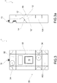
figure 2 is a perspective view of the assembled assembly; -
figures 3 and 3a are a front view and a side view of the assembly; -
figure 3b is an axial section of the assembly, assembled and provided with a lamp body; -
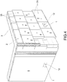
figure 4 shows a portion of the wall with a cladding insulation layer and lamp incorporated in the insulation layer by means of an assembly in the preceding figures; -
figure 5 is a perspective view in separate parts of the assembly according to the invention, in a variant embodiment; -
figure 6 is a perspective view of the assembly infigure 5 assembled; -
figures 7 and 7a are a front view and a side view of the assembly infigure 6 ; -
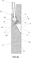
figure 8 shows a wall portion made of perforated bricks and a lamp incorporated in the wall by means of an assembly infigures 5-7 ; and -
figure 9 shows a wall portion made of heat-insulating and/or sound-absorbing blocks and a lamp incorporated in the wall by means of an assembly infigures 5-7 . - In the rest of the description, elements common to the different embodiments, or equivalent to each other, will be indicated at the same reference numbers.
- Moreover, unless otherwise specified, features described with reference to one embodiment may also be employed in other embodiments.
- In the description below, the terms `front' and 'rear' are used to refer to the wall, or a wall cladding thereof, which has a front side, facing outwards, and a rear side, opposite to the front side.
-
Figures 1-4 illustrate anassembly 1 to make a lamp incorporated in aninsulation layer 2 of awall cladding 3, consisting of polystyrene panels 4. - The
assembly 1 comprises afront body 10 wherein alight emission cavity 12 is obtained. - The
light emission cavity 12 extends from a rear body opening 14 to a front body opening 16. For example, thelight emission cavity 12 is delimited by a substantially flat top wall 12' and alower wall 12" inclined so that the light is emitted from thecavity 12 illuminating such inclinedlower wall 12". - The
front body 10 forms a substantiallyflat front surface 102 extending around the front body opening 16. - Moreover, the
front body 10 forms twoside walls 104 that define the thickness of thefront body 10. - The
assembly 1 comprises alamp housing 18 which forms internally alamp seat 182 suitable to house a lamp body 8 (figure 3b ). - The
lamp housing 18 delimits a rear housing opening 184 for the passage of the power supply cables of the lamp body and a front housing opening 186, for the emission of the light beam generated by thelamp body 8. - For example, the
front housing opening 186 is closed by anoptical element 82. - In one embodiment, the
rear housing opening 184 is suitable for the passage of acorrugated tube 19 that carries the power cables. - The
front housing opening 186 is suitable to face or be partially inserted into the rear body opening 14. - The
assembly 1 further comprises arear body 20 forming ahousing seat 22 suitable to receive with shape-coupling thelamp housing 18 protruding from the rear of thefront body 10. - The
rear body 20 is suitable to be coupled to thefront body 10 so as to form amonobloc panel 30 substantially parallelepiped in shape which completely incorporates thelamp housing 18. - This
monobloc panel 30 is suitable to be inserted and fixed in a corresponding volume formed between panels or blocks that form the cladding of the wall. - In addition, the
front surface 102 is suitable to receive afinishing layer 5 of the wall cladding. - In the example of
figures 1-4 , themonobloc panel 30 has at least the same thickness, preferably the same dimensions, as the polystyrene panels 4 and is used to replace one of these panels, as shown infigure 4 . - Preferably, the
front 10 and rear 20 bodies are also made of polystyrene, so that theassembly 1, in addition to obtaining the lamp incorporated in the insulation, also performs the function of thermal insulation like the other panels 4. - In one embodiment, in the
front body 10,pre-cut incisions 32 are made, which may be used to resize thefront body 10 according to the dimensions of the polystyrene panels between which themonobloc panel 30 is to be inserted. - In addition, in one embodiment, on the
front surface 102 of thefront body 10,reference marks 34 are made for the application ofbolts 35 for fastening themonobloc panel 30 to thewall 3. Thereference marks 34 are positioned in such a way that the bolts pass through themonobloc panel 30 in areas where the optical, electrical and mechanical elements of theassembly 1 are not present. - In one embodiment, the
rear body 20 is equipped withcoupling pins 36 that fit into corresponding coupling holes made in a rear wall of thefront body 10. - In one embodiment, the
front body 10 forms, in an upper portion thereof, arear cutout 38 that is filled by therear body 20. - In one embodiment, such
rear cutout 38 is delimited below by aninclined support wall 40 wherein thelight emission cavity 12 leads, forming the rear body opening 14. - Correspondingly, the
rear body 20 has alower wall 202 inclined to complement theinclined support wall 40 and suitable to rest on suchinclined support wall 40. - In the
rear body 20 there are, moreover, one ormore recesses corrugated tube 19. - In one embodiment, the
lamp housing 18 is provided, in a front portion thereof, with aperimeter flange 188 adapted to abut against theinclined support wall 40 of thefront body 10, which delimits the rear body opening 14. - In one embodiment, between the
perimeter flange 188 and theinclined support wall 40 there is interposed anannular plate 42 made of metallic material, for example steel. Especially in the case of a polystyrenefront body 10, theannular plate 42 serves as a reference and protection for supporting thelamp housing 18. While assembling theassembly 1, in effect, if thelamp housing 18 is pressed too hard against theinclined support wall 40, the latter could yield, compromising the perfect alignment between thelamp body 8 and thelight emission cavity 12. - In one embodiment, illustrated in
figures 5-7 but also applicable to theassembly 1 described above, thefront body opening 16 is delimited by anopening edge 44 protruding relative to thefront surface 102 which receives thefinishing layer 5. The height of thisopening edge 44 is substantially equal to the thickness of thefinishing layer 5 so that thefront opening 16 lies in an opening plane coplanar to the outer surface of thefinishing layer 5. - This contrivance allows the desired effect of perfect coplanarity to be obtained between the outer surface of the
finishing layer 5 and the edge that delimits the front body opening 16, highlighted on the left side offigures 4 ,8 and 9 , even in the case of a finishing layer of a certain thickness, such as for example in the case of plaster. - In one embodiment, the
opening edge 44 is connected to thefront surface 102 by means of aninclined joining surface 46 wherein it is also possible to obtain a Greek keycorrugated pattern 48 for adhering to thefinishing layer 5. -
Figures 5, 6 and7 show anassembly 100 that is particularly suitable for use in a perforated brick wall 104 (figure 8 ) or inblocks 106 made of a heat-insulating and/or sound-absorbing material, for example the cement-based material marketed under the name of Leca®. - The
assembly 100 differs from theassembly 1 described above in that, in theside parts 104 of thefront body 10,grooves 108 are made suitable to facilitate the connection with the adjacent bricks or blocks by means of cement. - Also object of the invention is a method for incorporating a lamp into a wall, or wall cladding, with panels 4, perforated
bricks 104 orblocks 106, using anassembly - The method provides for laying the cladding panels on the wall or making the wall out of perforated bricks or blocks.
- A space is made in the cladding or wall for the assembly to be inserted.
- The assembly, equipped with a lamp body, is inserted in said space.
- At this point, the assembly may be anchored to the wall or to adjacent panels, bricks or blocks.
- Finally, an outer finishing layer may be applied on the panels, bricks or blocks and on the front surface of the assembly.
- In one embodiment, before the application of the outer finishing layer, a protective cap is inserted into the
light emission cavity 12, preferably slightly recessed with respect to the edge that delimits the front opening of the cavity. The protective cap protects the inside ofcavity 12, and in particular the lowerinclined wall 12", from dirt caused during the application of thefinishing layer 5, especially in the case of plaster. After the application of the finishing layer, the protective cap may be removed. - If it is a question of incorporating the lamp into an insulation layer made of polystyrene panels, the assembly has at least the same depth as the polystyrene panels and the assembly is used in place of a polystyrene panel.
- The assembly is then anchored to the wall using bolts.
- If, on the other hand, a lamp is to be incorporated into a wall made of perforated bricks or thermo-insulating and/or sound-absorbing blocks, a recess is made in the wall having a volume substantially equal to that of the assembly.
- The assembly is then positioned in the recess and fixed to the adjacent bricks or blocks by means of cement.
- In all cases, the lamp is fully incorporated in the cladding or in the wall and the only visible part of it is the light emission cavity, with the outlet opening perfectly aligned with the outer surface of the finishing layer. The wall is perfectly continuous even at the monobloc panel and there is no trace of any joint.
- The assembly is pre-assembled, transported to the construction site and inserted as a single block in the recess made in the wall.
- In the case of an insulation layer made of polystyrene panels, the assembly is made in such a way as to form a polystyrene panel that is usable instead of a traditional panel.
- To the embodiments of the assembly and the method according to the invention, one skilled in the art may, to satisfy contingent needs, make modifications, adaptations and substitutions of some elements with others that are functionally equivalent, without departing from the scope of the following claims. Each of the features described as belonging to a possible embodiment may be implemented independently from the other described embodiments.
Claims (12)
- Assembly for making a lamp incorporated in a wall of perforated bricks or blocks, or in a panel cladding of a wall, comprising:- a front body (10) wherein a light emission cavity (12) is obtained extending from a rear body opening (14) to a front body opening (16);- a lamp housing (18) forming a lamp seat (182) suitable to house a lamp body (8) and defining a rear housing opening (184) for the passage of the power supply cables of the lamp body and a front housing opening (186) suitable to face or be partially inserted into the rear body opening (14); and- a rear body (20) forming a housing seat (22) suitable to receive with shape-coupling the lamp housing protruding from the rear of the front body (10),wherein said rear body (20) is suitable to be coupled to the front body (10) so as to form a monobloc panel (30) substantially parallelepiped in shape which completely incorporates the lamp housing, which is suitable to be inserted and fixed between the bricks, blocks or panels forming the wall or a cladding of the wall, and having a front surface (102) suitable to receive a finishing layer (5) of the wall or cladding of the wall.
- Assembly according to the preceding claim, wherein the front body (10) and the rear body (20) are made of polystyrene, the monobloc panel (30) having the same depth as polystyrene panels (4) for constructing insulation layers in a manner to be used in place of one of said polystyrene panels.
- Assembly according to the preceding claim, wherein in the front body (10) pre-cut incisions (32) are made which may be used to resize the front body (10) according to the dimensions of the polystyrene panels between which the monobloc panel is to be inserted.
- Assembly according to claim 2 or 3, wherein reference marks (34) are made in the front surface of the front body (10) for the application of bolts (35) for fastening the monobloc panel (30) to the wall.
- Assembly according claim 1 or 2, wherein grooves (108) are made in the side walls (104) of the front body (10) to facilitate fastening the monobloc panel (30) to adjacent perforated bricks or blocks using cement.
- Assembly according to any one of the preceding claims, wherein the front body opening (16) is delimited by an opening edge (44) protruding with respect to the front surface receiving the finishing layer, the height of said opening edge being substantially equal to the thickness of the finishing layer in such a way that the front opening lies in an opening plane coplanar to the outer surface of the finishing layer.
- Assembly according to claim 6, wherein the opening edge (44) is joined to the front surface (102) by means of an inclined joining surface (46) wherein is made a Greek key corrugated pattern (48) for adhering to the finishing layer.
- Assembly according to any one of the preceding claims, wherein the lamp housing (18) is provided, in a front portion thereof, with a perimeter flange (188) adapted to abut against an inclined support wall (40) of the front body, which delimits the rear body opening (14) .
- Assembly according to the preceding claim, comprising an annular plate (42) made of a metallic material suitable to be interposed between said perimeter flange and said inclined support wall of the front body.
- Method for incorporating a lamp according to claims 1-9 into a wall made of perforated bricks or blocks, or in a paneling of a wall, by means of an assembly according to any one of the preceding claims, comprising the steps of:a) laying the panels on the wall or constructing the wall of perforated bricks or blocks;b) obtaining, between said panels, perforated bricks or blocks, a space for inserting the assembly;c) positioning the assembly provided with a lamp body in said space;d) fixing the assembly to the wall, or to the panels, or to the adjacent bricks or blocks;e) applying an outer finishing layer on the panels, bricks or blocks and on the front surface of the assembly.
- Method according to the preceding claim, wherein the covering is an insulation layer formed of polystyrene panels, the assembly having at least the same depth as said polystyrene panels, and wherein:- steps b) and c) consist of using the assembly in place of a polystyrene panel;- step d) comprises fastening the assembly to the wall by means of fastening bolts.
- Method according to claim 10, wherein- step b) comprises making a recess in a wall made of perforated bricks or blocks, the recess having a volume substantially equal to that of the assembly;- step d) comprises anchoring the assembly to the adjacent bricks or blocks by using cement.
Applications Claiming Priority (1)
| Application Number | Priority Date | Filing Date | Title |
|---|---|---|---|
| IT102018000003553A IT201800003553A1 (en) | 2018-03-14 | 2018-03-14 | TOGETHER AND METHOD TO MAKE A LAMP INCORPORATED IN A WALL OR WALL COVERING |
Publications (2)
| Publication Number | Publication Date |
|---|---|
| EP3540308A1 EP3540308A1 (en) | 2019-09-18 |
| EP3540308B1 true EP3540308B1 (en) | 2020-09-30 |
Family
ID=62530376
Family Applications (1)
| Application Number | Title | Priority Date | Filing Date |
|---|---|---|---|
| EP18212763.9A Active EP3540308B1 (en) | 2018-03-14 | 2018-12-14 | Assembly and method for making a lamp incorporated in a wall or wall caldding |
Country Status (2)
| Country | Link |
|---|---|
| EP (1) | EP3540308B1 (en) |
| IT (1) | IT201800003553A1 (en) |
Citations (1)
| Publication number | Priority date | Publication date | Assignee | Title |
|---|---|---|---|---|
| EP3282185A1 (en) * | 2016-08-08 | 2018-02-14 | Depro Profiles SA | Floor strip |
Family Cites Families (7)
| Publication number | Priority date | Publication date | Assignee | Title |
|---|---|---|---|---|
| US20060291196A1 (en) * | 2005-06-14 | 2006-12-28 | Benavente Roy C | Illuminated stepping stone |
| CN2837671Y (en) * | 2005-07-12 | 2006-11-15 | 立碁电子工业股份有限公司 | Modularization brick lamp improves structure |
| US8376577B2 (en) * | 2007-11-05 | 2013-02-19 | Xicato, Inc. | Modular solid state lighting device |
| AT509687B1 (en) * | 2010-04-09 | 2012-04-15 | Hierzer Andreas | PARTITION WALL WITH INTEGRATED LIGHTING |
| CN204662207U (en) * | 2015-03-10 | 2015-09-23 | 惠州市绿湖园艺工程有限公司 | A kind of energy-conservation gardens special brick |
| US10895355B2 (en) * | 2015-11-13 | 2021-01-19 | Simes S.P.A. | Assembly and method for realising a lamp incorporated into a masonry wall |
| CN205502357U (en) * | 2016-05-11 | 2016-08-24 | 上海地东建筑设计事务所有限公司 | Build type daylighting unit by laying bricks or stones |
-
2018
- 2018-03-14 IT IT102018000003553A patent/IT201800003553A1/en unknown
- 2018-12-14 EP EP18212763.9A patent/EP3540308B1/en active Active
Patent Citations (1)
| Publication number | Priority date | Publication date | Assignee | Title |
|---|---|---|---|---|
| EP3282185A1 (en) * | 2016-08-08 | 2018-02-14 | Depro Profiles SA | Floor strip |
Also Published As
| Publication number | Publication date |
|---|---|
| EP3540308A1 (en) | 2019-09-18 |
| IT201800003553A1 (en) | 2019-09-14 |
Similar Documents
| Publication | Publication Date | Title |
|---|---|---|
| JP2007100336A (en) | Construction method for steel/concrete composite floor slab by use of precast concrete board | |
| JP2011074754A (en) | Method for manufacturing floor slab of steel-concrete composite using precast concrete panel | |
| KR101018411B1 (en) | Beam side form for deep deck and joint structure and construction method of reinforce concrete beam and slab for deep deck floor system thereof | |
| KR101139505B1 (en) | Timbering structure for tunnel and construction method thereof | |
| EP3540308B1 (en) | Assembly and method for making a lamp incorporated in a wall or wall caldding | |
| JP3696126B2 (en) | PRECAST CONCRETE PLATE, MANUFACTURING METHOD THEREOF, AND OUTER INSULATION STRUCTURE | |
| KR20080109595A (en) | Concrete pannel, joint member for concrete pannel and structure of concrete pannel using the same | |
| RU2118432C1 (en) | Construction panel | |
| KR200465477Y1 (en) | construction for permanent form | |
| JP3208530B2 (en) | Precast concrete formwork and structure using the same | |
| JPH09112029A (en) | Heat insulating panel made of polystyrene foaming body | |
| JP2010064373A (en) | Manufacturing method of heat insulating precast concrete panel | |
| KR101559106B1 (en) | Construction method of face brick | |
| KR20170069315A (en) | PC slab with lightweight block and manufacturing method thereof | |
| JP4159091B2 (en) | Partition wall structure | |
| KR100452977B1 (en) | Joint structure and construction method of RC beam and slab for slim floor system | |
| KR20200076306A (en) | Method For Construction Masonry Wall And Spacer For The Same | |
| JP3517398B2 (en) | Decorative plate block and its structure | |
| KR101804757B1 (en) | Prefabricated loess bricks with masonry joint | |
| KR101473099B1 (en) | Fixing Structure of Panel for External of Building | |
| JP2005325610A (en) | Floor structure | |
| KR100354717B1 (en) | Prefabricated Bathroom with the Integrated Wall | |
| JP2786412B2 (en) | Exterior panel covering structure of concrete building and covering construction method | |
| KR20050079383A (en) | A mold assembly apparatus for wall construction a building | |
| KR200317112Y1 (en) | Architectural brick |
Legal Events
| Date | Code | Title | Description |
|---|---|---|---|
| PUAI | Public reference made under article 153(3) epc to a published international application that has entered the european phase |
Free format text: ORIGINAL CODE: 0009012 |
|
| STAA | Information on the status of an ep patent application or granted ep patent |
Free format text: STATUS: THE APPLICATION HAS BEEN PUBLISHED |
|
| AK | Designated contracting states |
Kind code of ref document: A1 Designated state(s): AL AT BE BG CH CY CZ DE DK EE ES FI FR GB GR HR HU IE IS IT LI LT LU LV MC MK MT NL NO PL PT RO RS SE SI SK SM TR |
|
| AX | Request for extension of the european patent |
Extension state: BA ME |
|
| RAP1 | Party data changed (applicant data changed or rights of an application transferred) |
Owner name: SIMES S.P.A. |
|
| STAA | Information on the status of an ep patent application or granted ep patent |
Free format text: STATUS: REQUEST FOR EXAMINATION WAS MADE |
|
| 17P | Request for examination filed |
Effective date: 20200306 |
|
| RBV | Designated contracting states (corrected) |
Designated state(s): AL AT BE BG CH CY CZ DE DK EE ES FI FR GB GR HR HU IE IS IT LI LT LU LV MC MK MT NL NO PL PT RO RS SE SI SK SM TR |
|
| GRAP | Despatch of communication of intention to grant a patent |
Free format text: ORIGINAL CODE: EPIDOSNIGR1 |
|
| STAA | Information on the status of an ep patent application or granted ep patent |
Free format text: STATUS: GRANT OF PATENT IS INTENDED |
|
| INTG | Intention to grant announced |
Effective date: 20200526 |
|
| GRAS | Grant fee paid |
Free format text: ORIGINAL CODE: EPIDOSNIGR3 |
|
| GRAA | (expected) grant |
Free format text: ORIGINAL CODE: 0009210 |
|
| STAA | Information on the status of an ep patent application or granted ep patent |
Free format text: STATUS: THE PATENT HAS BEEN GRANTED |
|
| AK | Designated contracting states |
Kind code of ref document: B1 Designated state(s): AL AT BE BG CH CY CZ DE DK EE ES FI FR GB GR HR HU IE IS IT LI LT LU LV MC MK MT NL NO PL PT RO RS SE SI SK SM TR |
|
| REG | Reference to a national code |
Ref country code: GB Ref legal event code: FG4D Ref country code: CH Ref legal event code: EP |
|
| REG | Reference to a national code |
Ref country code: AT Ref legal event code: REF Ref document number: 1319158 Country of ref document: AT Kind code of ref document: T Effective date: 20201015 |
|
| REG | Reference to a national code |
Ref country code: DE Ref legal event code: R096 Ref document number: 602018008302 Country of ref document: DE |
|
| REG | Reference to a national code |
Ref country code: IE Ref legal event code: FG4D |
|
| PG25 | Lapsed in a contracting state [announced via postgrant information from national office to epo] |
Ref country code: SE Free format text: LAPSE BECAUSE OF FAILURE TO SUBMIT A TRANSLATION OF THE DESCRIPTION OR TO PAY THE FEE WITHIN THE PRESCRIBED TIME-LIMIT Effective date: 20200930 Ref country code: GR Free format text: LAPSE BECAUSE OF FAILURE TO SUBMIT A TRANSLATION OF THE DESCRIPTION OR TO PAY THE FEE WITHIN THE PRESCRIBED TIME-LIMIT Effective date: 20201231 Ref country code: FI Free format text: LAPSE BECAUSE OF FAILURE TO SUBMIT A TRANSLATION OF THE DESCRIPTION OR TO PAY THE FEE WITHIN THE PRESCRIBED TIME-LIMIT Effective date: 20200930 Ref country code: NO Free format text: LAPSE BECAUSE OF FAILURE TO SUBMIT A TRANSLATION OF THE DESCRIPTION OR TO PAY THE FEE WITHIN THE PRESCRIBED TIME-LIMIT Effective date: 20201230 Ref country code: HR Free format text: LAPSE BECAUSE OF FAILURE TO SUBMIT A TRANSLATION OF THE DESCRIPTION OR TO PAY THE FEE WITHIN THE PRESCRIBED TIME-LIMIT Effective date: 20200930 Ref country code: BG Free format text: LAPSE BECAUSE OF FAILURE TO SUBMIT A TRANSLATION OF THE DESCRIPTION OR TO PAY THE FEE WITHIN THE PRESCRIBED TIME-LIMIT Effective date: 20201230 |
|
| REG | Reference to a national code |
Ref country code: AT Ref legal event code: MK05 Ref document number: 1319158 Country of ref document: AT Kind code of ref document: T Effective date: 20200930 |
|
| PG25 | Lapsed in a contracting state [announced via postgrant information from national office to epo] |
Ref country code: LV Free format text: LAPSE BECAUSE OF FAILURE TO SUBMIT A TRANSLATION OF THE DESCRIPTION OR TO PAY THE FEE WITHIN THE PRESCRIBED TIME-LIMIT Effective date: 20200930 Ref country code: RS Free format text: LAPSE BECAUSE OF FAILURE TO SUBMIT A TRANSLATION OF THE DESCRIPTION OR TO PAY THE FEE WITHIN THE PRESCRIBED TIME-LIMIT Effective date: 20200930 |
|
| REG | Reference to a national code |
Ref country code: NL Ref legal event code: MP Effective date: 20200930 |
|
| REG | Reference to a national code |
Ref country code: LT Ref legal event code: MG4D |
|
| PG25 | Lapsed in a contracting state [announced via postgrant information from national office to epo] |
Ref country code: SM Free format text: LAPSE BECAUSE OF FAILURE TO SUBMIT A TRANSLATION OF THE DESCRIPTION OR TO PAY THE FEE WITHIN THE PRESCRIBED TIME-LIMIT Effective date: 20200930 Ref country code: LT Free format text: LAPSE BECAUSE OF FAILURE TO SUBMIT A TRANSLATION OF THE DESCRIPTION OR TO PAY THE FEE WITHIN THE PRESCRIBED TIME-LIMIT Effective date: 20200930 Ref country code: CZ Free format text: LAPSE BECAUSE OF FAILURE TO SUBMIT A TRANSLATION OF THE DESCRIPTION OR TO PAY THE FEE WITHIN THE PRESCRIBED TIME-LIMIT Effective date: 20200930 Ref country code: RO Free format text: LAPSE BECAUSE OF FAILURE TO SUBMIT A TRANSLATION OF THE DESCRIPTION OR TO PAY THE FEE WITHIN THE PRESCRIBED TIME-LIMIT Effective date: 20200930 Ref country code: PT Free format text: LAPSE BECAUSE OF FAILURE TO SUBMIT A TRANSLATION OF THE DESCRIPTION OR TO PAY THE FEE WITHIN THE PRESCRIBED TIME-LIMIT Effective date: 20210201 Ref country code: EE Free format text: LAPSE BECAUSE OF FAILURE TO SUBMIT A TRANSLATION OF THE DESCRIPTION OR TO PAY THE FEE WITHIN THE PRESCRIBED TIME-LIMIT Effective date: 20200930 |
|
| PG25 | Lapsed in a contracting state [announced via postgrant information from national office to epo] |
Ref country code: ES Free format text: LAPSE BECAUSE OF FAILURE TO SUBMIT A TRANSLATION OF THE DESCRIPTION OR TO PAY THE FEE WITHIN THE PRESCRIBED TIME-LIMIT Effective date: 20200930 Ref country code: AL Free format text: LAPSE BECAUSE OF FAILURE TO SUBMIT A TRANSLATION OF THE DESCRIPTION OR TO PAY THE FEE WITHIN THE PRESCRIBED TIME-LIMIT Effective date: 20200930 Ref country code: AT Free format text: LAPSE BECAUSE OF FAILURE TO SUBMIT A TRANSLATION OF THE DESCRIPTION OR TO PAY THE FEE WITHIN THE PRESCRIBED TIME-LIMIT Effective date: 20200930 Ref country code: PL Free format text: LAPSE BECAUSE OF FAILURE TO SUBMIT A TRANSLATION OF THE DESCRIPTION OR TO PAY THE FEE WITHIN THE PRESCRIBED TIME-LIMIT Effective date: 20200930 Ref country code: IS Free format text: LAPSE BECAUSE OF FAILURE TO SUBMIT A TRANSLATION OF THE DESCRIPTION OR TO PAY THE FEE WITHIN THE PRESCRIBED TIME-LIMIT Effective date: 20210130 |
|
| PG25 | Lapsed in a contracting state [announced via postgrant information from national office to epo] |
Ref country code: NL Free format text: LAPSE BECAUSE OF FAILURE TO SUBMIT A TRANSLATION OF THE DESCRIPTION OR TO PAY THE FEE WITHIN THE PRESCRIBED TIME-LIMIT Effective date: 20200930 Ref country code: SK Free format text: LAPSE BECAUSE OF FAILURE TO SUBMIT A TRANSLATION OF THE DESCRIPTION OR TO PAY THE FEE WITHIN THE PRESCRIBED TIME-LIMIT Effective date: 20200930 |
|
| REG | Reference to a national code |
Ref country code: DE Ref legal event code: R097 Ref document number: 602018008302 Country of ref document: DE |
|
| PLBE | No opposition filed within time limit |
Free format text: ORIGINAL CODE: 0009261 |
|
| STAA | Information on the status of an ep patent application or granted ep patent |
Free format text: STATUS: NO OPPOSITION FILED WITHIN TIME LIMIT |
|
| PG25 | Lapsed in a contracting state [announced via postgrant information from national office to epo] |
Ref country code: DK Free format text: LAPSE BECAUSE OF FAILURE TO SUBMIT A TRANSLATION OF THE DESCRIPTION OR TO PAY THE FEE WITHIN THE PRESCRIBED TIME-LIMIT Effective date: 20200930 Ref country code: MC Free format text: LAPSE BECAUSE OF FAILURE TO SUBMIT A TRANSLATION OF THE DESCRIPTION OR TO PAY THE FEE WITHIN THE PRESCRIBED TIME-LIMIT Effective date: 20200930 |
|
| REG | Reference to a national code |
Ref country code: BE Ref legal event code: MM Effective date: 20201231 |
|
| 26N | No opposition filed |
Effective date: 20210701 |
|
| PG25 | Lapsed in a contracting state [announced via postgrant information from national office to epo] |
Ref country code: IT Free format text: LAPSE BECAUSE OF FAILURE TO SUBMIT A TRANSLATION OF THE DESCRIPTION OR TO PAY THE FEE WITHIN THE PRESCRIBED TIME-LIMIT Effective date: 20200930 Ref country code: LU Free format text: LAPSE BECAUSE OF NON-PAYMENT OF DUE FEES Effective date: 20201214 Ref country code: IE Free format text: LAPSE BECAUSE OF NON-PAYMENT OF DUE FEES Effective date: 20201214 |
|
| PG25 | Lapsed in a contracting state [announced via postgrant information from national office to epo] |
Ref country code: SI Free format text: LAPSE BECAUSE OF FAILURE TO SUBMIT A TRANSLATION OF THE DESCRIPTION OR TO PAY THE FEE WITHIN THE PRESCRIBED TIME-LIMIT Effective date: 20200930 |
|
| PG25 | Lapsed in a contracting state [announced via postgrant information from national office to epo] |
Ref country code: IS Free format text: LAPSE BECAUSE OF FAILURE TO SUBMIT A TRANSLATION OF THE DESCRIPTION OR TO PAY THE FEE WITHIN THE PRESCRIBED TIME-LIMIT Effective date: 20210130 Ref country code: TR Free format text: LAPSE BECAUSE OF FAILURE TO SUBMIT A TRANSLATION OF THE DESCRIPTION OR TO PAY THE FEE WITHIN THE PRESCRIBED TIME-LIMIT Effective date: 20200930 Ref country code: MT Free format text: LAPSE BECAUSE OF FAILURE TO SUBMIT A TRANSLATION OF THE DESCRIPTION OR TO PAY THE FEE WITHIN THE PRESCRIBED TIME-LIMIT Effective date: 20200930 Ref country code: CY Free format text: LAPSE BECAUSE OF FAILURE TO SUBMIT A TRANSLATION OF THE DESCRIPTION OR TO PAY THE FEE WITHIN THE PRESCRIBED TIME-LIMIT Effective date: 20200930 |
|
| PG25 | Lapsed in a contracting state [announced via postgrant information from national office to epo] |
Ref country code: MK Free format text: LAPSE BECAUSE OF FAILURE TO SUBMIT A TRANSLATION OF THE DESCRIPTION OR TO PAY THE FEE WITHIN THE PRESCRIBED TIME-LIMIT Effective date: 20200930 |
|
| PG25 | Lapsed in a contracting state [announced via postgrant information from national office to epo] |
Ref country code: BE Free format text: LAPSE BECAUSE OF NON-PAYMENT OF DUE FEES Effective date: 20201231 |
|
| REG | Reference to a national code |
Ref country code: CH Ref legal event code: PL |
|
| PG25 | Lapsed in a contracting state [announced via postgrant information from national office to epo] |
Ref country code: LI Free format text: LAPSE BECAUSE OF NON-PAYMENT OF DUE FEES Effective date: 20211231 Ref country code: CH Free format text: LAPSE BECAUSE OF NON-PAYMENT OF DUE FEES Effective date: 20211231 |
|
| PGFP | Annual fee paid to national office [announced via postgrant information from national office to epo] |
Ref country code: GB Payment date: 20231220 Year of fee payment: 6 |
|
| PGFP | Annual fee paid to national office [announced via postgrant information from national office to epo] |
Ref country code: FR Payment date: 20231220 Year of fee payment: 6 Ref country code: DE Payment date: 20231214 Year of fee payment: 6 |