EP3540262B1 - Transmission par courroie à roue planétaire - Google Patents
Transmission par courroie à roue planétaire Download PDFInfo
- Publication number
- EP3540262B1 EP3540262B1 EP19151097.3A EP19151097A EP3540262B1 EP 3540262 B1 EP3540262 B1 EP 3540262B1 EP 19151097 A EP19151097 A EP 19151097A EP 3540262 B1 EP3540262 B1 EP 3540262B1
- Authority
- EP
- European Patent Office
- Prior art keywords
- belt
- planetary
- wheels
- sun
- gears
- Prior art date
- Legal status (The legal status is an assumption and is not a legal conclusion. Google has not performed a legal analysis and makes no representation as to the accuracy of the status listed.)
- Active
Links
- 230000008878 coupling Effects 0.000 claims description 7
- 238000010168 coupling process Methods 0.000 claims description 7
- 238000005859 coupling reaction Methods 0.000 claims description 7
- 230000005540 biological transmission Effects 0.000 description 25
- 235000012431 wafers Nutrition 0.000 description 4
- 238000010276 construction Methods 0.000 description 3
- 238000012423 maintenance Methods 0.000 description 3
- 238000009434 installation Methods 0.000 description 2
- 206010034016 Paronychia Diseases 0.000 description 1
- 230000015572 biosynthetic process Effects 0.000 description 1
- 238000005352 clarification Methods 0.000 description 1
- 239000011248 coating agent Substances 0.000 description 1
- 238000000576 coating method Methods 0.000 description 1
- 230000000295 complement effect Effects 0.000 description 1
- 230000000694 effects Effects 0.000 description 1
- 238000005461 lubrication Methods 0.000 description 1
- 230000002093 peripheral effect Effects 0.000 description 1
- 239000004065 semiconductor Substances 0.000 description 1
- 238000004088 simulation Methods 0.000 description 1
Images


Classifications
-
- F—MECHANICAL ENGINEERING; LIGHTING; HEATING; WEAPONS; BLASTING
- F16—ENGINEERING ELEMENTS AND UNITS; GENERAL MEASURES FOR PRODUCING AND MAINTAINING EFFECTIVE FUNCTIONING OF MACHINES OR INSTALLATIONS; THERMAL INSULATION IN GENERAL
- F16H—GEARING
- F16H7/00—Gearings for conveying rotary motion by endless flexible members
- F16H7/02—Gearings for conveying rotary motion by endless flexible members with belts; with V-belts
- F16H7/023—Gearings for conveying rotary motion by endless flexible members with belts; with V-belts with belts having a toothed contact surface or regularly spaced bosses or hollows for slipless or nearly slipless meshing with complementary profiled contact surface of a pulley
-
- F—MECHANICAL ENGINEERING; LIGHTING; HEATING; WEAPONS; BLASTING
- F16—ENGINEERING ELEMENTS AND UNITS; GENERAL MEASURES FOR PRODUCING AND MAINTAINING EFFECTIVE FUNCTIONING OF MACHINES OR INSTALLATIONS; THERMAL INSULATION IN GENERAL
- F16H—GEARING
- F16H1/00—Toothed gearings for conveying rotary motion
- F16H1/28—Toothed gearings for conveying rotary motion with gears having orbital motion
- F16H2001/2881—Toothed gearings for conveying rotary motion with gears having orbital motion comprising two axially spaced central gears, i.e. ring or sun gear, engaged by at least one common orbital gear wherein one of the central gears is forming the output
-
- F—MECHANICAL ENGINEERING; LIGHTING; HEATING; WEAPONS; BLASTING
- F16—ENGINEERING ELEMENTS AND UNITS; GENERAL MEASURES FOR PRODUCING AND MAINTAINING EFFECTIVE FUNCTIONING OF MACHINES OR INSTALLATIONS; THERMAL INSULATION IN GENERAL
- F16H—GEARING
- F16H1/00—Toothed gearings for conveying rotary motion
- F16H1/28—Toothed gearings for conveying rotary motion with gears having orbital motion
- F16H2001/289—Toothed gearings for conveying rotary motion with gears having orbital motion comprising two or more coaxial and identical sets of orbital gears, e.g. for distributing torque between the coaxial sets
Definitions
- the invention relates to a planetary gear transmission according to the preamble of claim 1.
- Epicyclic gears using power and torque transmission through belt drives are known. So reveals the DE 8513152 U1 an epicyclic gearing designed as a belt gear, in which the belt is passed around the sun gear and between planet gears and a ring gear in such a way that all gears are connected to one another in a rotating manner.
- a belt toothed on both sides is preferably used here, which loops around the externally toothed sun gear and the externally toothed planetary gears and engages with the rear toothing in the internal toothing of the internal gear.
- the planet gears are rotatably mounted on a web in such a way that the double-sided toothed belt running through the space between the planet gears, the ring gear, engages both the external toothing of the planetary gear and the internal toothing of the ring gear.
- the teeth of the sun gear and the planet gears do not mesh directly with one another but are connected to one another via the drive belt.
- the simultaneous engagement of the belt in the externally toothed planetary gears and in the internally toothed ring gear can lead to differences in the peripheral speed of the gears leading to disadvantageous force and tension conditions within the toothed belt, which reduce the service life.
- the advantage of such a planetary belt drive is a lightweight construction, a low-vibration and quiet drive and largely freedom from maintenance.
- the DE 10 2015 007376 A1 discloses an electronic parking brake in which the piston actuating the brake shoes is moved with the aid of a spindle which converts a rotary movement, ie a rotary movement into a translational movement.
- the spindle is driven by an electric motor to which a reduction gear is connected.
- This gear is designed as a type of planetary gear with belt drive.
- a toothed belt surrounds the sun gear and is pressed against the internal toothing of a ring gear connected to the web via planet gears or belt support wheels mounted in a web. The belt is brought into engagement with the ring gear in such a way that the rotational movement of the sun gear is transmitted in a reduced manner.
- Belts and support wheels can also be designed in such a way that the back of the belt slides on the belt support wheels.
- the engagement between the support wheel and the ring gear which is forced by a certain amount of pressure, places greater stress on the belt, which means that such a drive is only recommended for the transmission of lower forces.
- the U.S. 3,543,608 discloses a belt transmission provided as a differential in a vehicle drive with revolving planets, in which a drive belt designed as a V-belt is rotated by 90 °, ie is twisted and lies in different planes Planet and sun gears wrapped around.
- the planet gears are each designed as a double and mounted on a common axis within a rotating web.
- the axes of the planet gears on the one hand and the axes of the sun gear and the planet carrier cross at right angles in space.
- the drive is intended for smaller, light vehicles such as golf caddies.
- the twist that is to say the twisting of the drive belt, is disadvantageous in a certain way, since the side areas of the belt are particularly stressed here.
- the U.S. 5,445,572 discloses a differential gear for a motor vehicle, in which the drive torque is introduced via the web or the planet carrier and is transmitted to the two rear axles and thus to the rear wheels via two coaxial output gears.
- the planet gears in the carrier and the output gears are connected to one another via a toothed belt and thus each form a belt drive. It is a version with a double or multiple and one with a single belt drive disclosed.
- the belt wraps around each of the two driven gears and the planetary gears, the latter simultaneously serving to twist the belt by 90 ° and divert it through a recess in the web or carrier to the respective other driven gear.
- Such a differential gear enables relatively high torques to be transmitted, as occur in a motor vehicle drive.
- the twist is also disadvantageous here, here even a twofold rotation of the toothed belt by 90 ° and a corresponding deflection, which generates very strong forces in particular in the side areas of the belt.
- additional pressure rollers and flanged disks which are required to guide the belts on the planetary gears, generate high frictional forces and thus wear.
- the WO 2011/156371 A1 discloses a device for coating semiconductor wafers, in which the wafers are positioned in a reactor on a carrier and rotate both with the carrier and about their own axis.
- the rotation around its own axis is achieved in one embodiment in that a Kind of belt-driven planetary gear is provided, with the individual wafers being stored on the planet.
- a kind of belt-driven planetary gear is provided, with the individual wafers being stored on the planet.
- the DE 801801 C discloses an epicyclic transmission which is suitable for realizing high transmission or reduction ratios.
- an endless, flexible traction element preferably an endless rubber V-belt, is used for power transmission between two wheels following in the power path.
- V-belt endless rubber V-belt
- the object of the invention was therefore to provide an epicyclic gearing designed as a belt or traction mechanism, which combines the advantages of simple maintenance and negligible lubrication with high power transmission, which has a low weight compared to the usual epicyclic gears, in particular low inertia and which is characterized by a greatly reduced noise emission and runs with low vibrations.
- one of the belt drives connecting a sun gear with the planet gears is designed with a belt running back and forth in such a way that the associated sun gear rotates opposite to the direction of rotation of the planet gears with respect to the planet carrier, the belt rotating the planet gears on the front and the sun gear on the back , while the other belt drive has a belt which rotates the planet gears and the associated sun gear only on the front side.
- a plurality of belt drives are therefore initially provided, namely each of the sun gears being connected to the planet gears via at least one of the belt drives. This ensures a high level of power transmission. Due to the spatially parallel alignment of the shafts connected to the sun gears and the axes of the planet gears, no twisting, i.e. no twist, of the belts of the respective belt drives is necessary.
- the speed coupling between the belt drives then takes place in a simple manner via at least one planet gear that is wrapped together, or better, via several planet gears that are wrapped together.
- a belt weighs little and can be looped around any number of belt pulleys or pulleys in a power-transmitting manner through the simplest length adjustment - within limits, of course.
- one of the belt drives connecting a sun gear with the planetary gears is designed with a belt running back and forth in such a way that, with respect to the planet carrier, the associated sun gear can be rotated in the opposite direction to the direction of rotation of the planetary gears.
- Such a reversal of the direction of rotation with the help of a belt running back and forth within one of the belt drives results in the possibility of using it as a Differential gear or summation gear in an extremely simple design without complicated deflections, bushings or larger moving masses.
- the belt preferably runs around the planet gears on the front side and the sun gear on the back, in order to further simplify the design and to achieve the smallest possible dimensions of the transmission.
- the epicyclic gearing according to the invention is designed as a differential or differential gear and the belt drives are designed as toothed belt drives.
- the planet carrier is drivably connected to a drive shaft, that is to say, for example, to a shaft driven by the engine of a vehicle, which transmits the drive torque to the planet carrier.
- Two sun gears arranged concentrically to the planet carrier are connected to the output shafts in a rotationally fixed manner, that is to say, in the case of a vehicle drive, to the drive shafts of the drive wheels.
- the sun gears and the planet gears are externally toothed and each of the sun gears is connected to the planet gears via at least one toothed belt drive, the toothed belt of a toothed belt drive being designed with a front and a rear toothing and the planet gears rotating on the front and the associated sun gear rotating on the back and the other toothed belt drive Toothed belt has a one-sided, front-side toothing, which revolves around the planet gears and the associated sun gear on the front side. In relation to the planet carrier, the sun gear belonging to the belt drive with the front and a rear toothed belt can be rotated opposite to the direction of rotation of the planet gears and opposite to the other sun gear.
- the planet carrier can also be designed as a planetary cage or cage.
- conventional differential gears generally have meshing metallic gears, for example bevel gears or spur gears, and thus introduce correspondingly high weights into a vehicle
- the inventive Formation of a planetary gear drive with toothed belt drives a transmission of large forces or high torques with low weight.
- the epicyclic gearing is suitable for use as a differential in a motor vehicle drive with high torques.
- Another advantageous embodiment is that, in a planetary gear transmission according to the invention, the speed coupling of the belt drives takes place via two planet gears wrapped together by their two belts, with toothed belt drives correspondingly via two externally toothed planet gears wrapped together by their two toothed belts.
- toothed belt drives correspondingly via two externally toothed planet gears wrapped together by their two toothed belts.
- further planet gears can be looped around by the respective belts of the belt drives and thus speed-coupled. In this way, the transmission of torques can be divided between several planet gears. In the case of toothed belts, this reduces the tooth root tensions, so that greater performance can be achieved.
- a further advantageous embodiment consists in that the two sun gears are arranged in front of one another and the planet gears that are wrapped together have such a width that the belts of the two belt drives wrap around the planet gears next to one another.
- the planet gears then approximately have a width which, apart from the required minimum distances and the compensation of tolerances, essentially corresponds to the sum of the width of the two sun gears.
- toothed belt drives in which the toothed belts of the two belt drives then engage in the toothing of the planetary gears that are wrapped around one another in a circumferential manner.
- the planetary gears and the other wrapped gears with corresponding complementary ones Profiles for guiding the belts should be provided.
- the planet carrier is designed as a cup-shaped or drum-shaped housing provided with a cover, namely as a so-called differential cage, and that the planet gears or the axes of the planet gears are rotatably mounted on the one hand in the drum base and on the other hand in the drum cover, wherein a shaft connected to a sun gear is guided out of the housing through the drum base and the shaft connected to the other sun gear is guided out of the housing through the drum cover.
- This also means that the installation space for the epicyclic gear is minimized.
- a sun gear or the shaft connected to it is rotatably mounted and supported on one side in the drum base and the other sun gear or the shaft connected to it is rotatably supported on one side in the drum cover.
- bearings known from other gear designs are also possible, for example one in which a common axis is formed for the two sun gears and the shafts connected to the sun gears are designed as hollow shafts and are mounted and supported on this axis. Tapered roller bearings, for example, which also absorb axial forces, are suitable for this purpose.
- Another advantageous embodiment is that at least four planet gears are mounted in the planet carrier.
- the use of four planetary gears, two of which are looped around by two toothed belt drives for speed coupling, has proven to be particularly suitable as a compromise between size and required power transmission.
- a further advantageous embodiment of an epicyclic gearing with four planetary gears consists in the fact that it is configured with a belt that runs around the front and back Belt drive engages all four planetary gears revolving and which engages revolvingly with a belt running around the front only in two planetary gears, so that the belt drives are again connected to one another in speed-coupled fashion via two planet gears wrapped around by their belts. This also makes a good compromise between size and torques or. Power transfer supported.
- a further advantageous embodiment is available, which consists in equipping the epicyclic gear transmission according to the invention with several parallel belt drives for each center or sun gear that transmit power in the same direction.
- the epicyclic gears according to the invention which are so lightweight and compact, are well suited as differential or differential gears for a drive axle of a motor vehicle, preferably for the drive axle of an electric vehicle.
- such an epicyclic gearing can advantageously also be used as a summation gearing, the center gears or sun gears being drivable and the planet carrier being connected to the output shaft.
- the center gears or sun gears being drivable
- the planet carrier being connected to the output shaft.
- several electric motors in a vehicle can transmit power to one drive shaft.
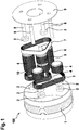
- Fig. 1 shows a planetary gear transmission 100 according to the invention with three shafts, designed as a toothed belt transmission.
- Figure 1 executed in the form of a perspective exploded view.
- the planetary gear transmission 100 is constructed as a differential gear that distributes drive torque to two rear drive wheels of a vehicle.
- the differential gear serves in particular to compensate for different speeds between the wheel on the inside and outside of the curve when driving through bends.
- the planetary carrier or gear cage 1 can be driven and is connected to a drive shaft, not shown here, for transmitting a drive torque, for example by means of further gears.
- the pot-shaped planet carrier 1, in cooperation with the housing cover 9, serves to accommodate and support the pairs of planet gears 4 and 6.
- the planet gears 6 are more than twice as wide as the planet gears 4.
- the two planet gears 4 and the two planet gears 6 are each mounted on the one hand in the cup-shaped carrier 1 and on the other hand in the housing cover 9 with the aid of their axes 8 and corresponding bearings 2.
- the two sun gears 5 and 10 are arranged concentric to the planet carrier and lying in front of one another.
- the jointly wrapped planet gears 6 have such a width that the belts 3 and 7 of the two belt drives wrap around the planet gears 6 next to one another.
- Two sun gears 5 and 10 are arranged concentrically to the planet carrier 1 and connected in a rotationally fixed manner to one of the output shafts within the gear cage formed from the cup-shaped planet carrier 1 and the housing cover 9. These output shafts are not shown here and are commonly used in the differential gear shown here for a rear-wheel drive of a vehicle Designated drive shafts of the rear wheels.
- the sun gear 10 is here connected to the left rear wheel via the corresponding shaft and the sun gear 5 is connected to the right rear wheel via a shaft.
- the shafts connected to the sun gears and the axes 8 of the planet gears 4, 6 are spatially parallel.
- two belt drives with toothed belts 3 and 7 are provided, namely one belt drive for each of the sun gears 5 and 10, so that each of the sun gears is connected to the or some planet gears via one of the belt drives.
- Sun gears 5, 10 and planet gears 4 and 6 are externally toothed.
- the two belt drives are speed-coupled.
- the two belt drives are in fact connected to one another via the two planet gears 6 around which the belts 3 and 7 are wrapped, whereby an identical belt circulation speed and thus a speed coupling is enforced.
- the belt drive 3 which connects the sun gear 10 to the planet gears, is designed with a toothed belt running around the front and back, i.e. a toothed belt 3 provided with teeth on both sides, so that the associated sun gear 10 in relation to the planet carrier 1 is opposite to the direction of rotation of the planet gears is rotatable, the belt 3 rotating the planet gears 4 and 6 on the front side and the sun gear 10 on the rear side.
- the other toothed belt drive which connects the sun gear 5 to the planetary gears, has a toothed belt 7 which is only provided with a one-sided, front-side toothing and which revolves around the planetary gears and the associated sun gear 5 on the front side.
- the two sun gears 5 and 10 would then also rotate in opposite directions, since the sun gear 5 is wrapped around the front and the sun gear 10 is wrapped around the back by the respective belt.
- the speed coupling of the belt drives or belts 3 and 7 takes place via two planet gears 6, which are wrapped together by the two belts.
- the belt 7 only wraps around these two planet gears 6, while the belt 3 wraps around all four planet gears, namely the planet gears 4 and the planet gears 6.
- Fig. 2 shows for clarification in a perspective sketch of the assembly once again the circulation and toothing relationships of the epicyclic gear according to the invention and designed as a differential or differential gear with three shafts, for the sake of clarity shown without a planet carrier or gear cage.
- the two concentrically arranged sun gears 5 and 10 can be seen here, which, like the planet gears 4 and 6, are externally toothed.
- Each of the sun gears 5, 10 is incorporated in a toothed belt drive and connected to the planet gears 4, 6 via toothed belts 3, 7.
- the toothed belt 3 of the toothed belt drive belonging to the sun gear 10 is designed with a front and a rear toothing and revolves around the planet gears 4, 6 on the front side and the sun gear 10 on the rear side.
- the other toothed belt 7 of the toothed belt drive belonging to the sun gear 5 only has a one-sided, namely front-side toothing, which the planetary gears 6 and the sun gear 5 rotates at the front.
- the shaft extension of the shaft 11 on the sun gear 5 and the shaft extension of the shaft 12 on the sun gear 10 can now also be seen here, which basically illustrate how the sun gears are connected to the respective output shafts or drive shafts of the rear wheels.
- Fig. 3 again a sketch of the planetary gear assembly in the assembly, also without representation of the planet carrier or gear cage. It can be clearly seen here once again that the belt 3 revolves the planetary gear pairs 4 and 6 on the front side and the associated sun gear 10 on the back, while the belt 7 revolves the sun gear 5 and only the two planet gears of the planetary pair 6 on the front side.
- the epicyclic belt gear / differential gear according to the invention is characterized by low-maintenance and dry running, by a cost-effective and light structure, by lower mass inertia and by low-noise running.
- the planet carrier does not necessarily have to be designed as a driven gear cage, but can be arranged concentrically with and within a further internally toothed center gear, namely a ring gear.
- the internally toothed ring gear can then mesh directly with the external toothing of some or all of the planetary gears or it can be in engagement via the belt that is toothed on both sides.
- Such a design allows the most varied types of planetary gears to be implemented with the aid of an epicyclic belt drive according to the invention.
Landscapes
- Engineering & Computer Science (AREA)
- General Engineering & Computer Science (AREA)
- Mechanical Engineering (AREA)
- Retarders (AREA)
Claims (11)
- Train épicycloïdal (100), comprenant au moins trois arbres, réalisé sous la forme d'une transmission à courroie ou à moyen de traction, comprenant un porte-satellites (1) relié de manière verrouillée en rotation à un premier arbre ou par un engrenage, destiné à recevoir et à loger des roues planétaires (4, 6), et comprenant deux roues solaires (5, 10) disposées de manière concentrique par rapport au porte-satellites et reliées de manière verrouillée en rotation à respectivement l'un des arbres supplémentaires (11, 12),- les arbres reliés aux roues solaires (5, 10) et les arbres (8) des roues planétaires (4, 6) étant alignés en parallèle dans l'espace,- dans lequel au moins deux entraînements par courroie sont prévus, et chacune des roues solaires (5, 10) est reliée aux roues planétaires (4, 6) par l'un des entraînements par courroie,- les entraînements par courroie étant reliés l'un à l'autre par couplage de vitesse de rotation par l'intermédiaire d'au moins une roue planétaire (6) commune sur laquelle sont enroulées leurs courroies (3, 7),caractérisé en ce que l'un des entraînements par courroie reliant une roue solaire (10) aux roues planétaires, doté d'une courroie (3) tournante en face avant et en face arrière, est réalisé de telle sorte que par rapport au porte-satellites (1), la roue solaire associée (10) tourne à l'opposé de la direction de rotation des roues planétaires (4, 6), la courroie (3) tournant autour des roues planétaires (4, 6) en face avant et autour de la roue solaire (10) en face arrière, alors que l'autre entraînement par courroie présente une courroie (7) qui tourne autour des roues planétaires (6) et autour de la roue solaire associée (5) en face avant.
- Train épicycloïdal selon la revendication 1, réalisé sous forme de différentiel ou engrenage différentiel à trois arbres, dans lequel le porte-satellites (1) est relié à un arbre d'entraînement de manière à pouvoir être entraîné, et deux roues solaires (5, 10), disposées de manière concentrique par rapport au porte-satellites, sont reliées aux arbres de sortie (11, 12) de manière verrouillée en rotation, caractérisé en ce que les roues solaires (5, 10) et les roues planétaires (4, 6) présentent une denture extérieure et chacune des roues solaires (5, 10) est reliée aux roues planétaires (4, 6) par au moins un entraînement par courroie, dans lequel la courroie crantée (3) d'un entraînement par courroie crantée est réalisée avec une denture en face avant et une denture en face arrière et tourne autour des roues planétaires (4, 6) en face avant et autour de la roue solaire associée (10) en face arrière, et l'autre entraînement par courroie crantée présente une courroie crantée (7) dotée d'une denture unilatérale en face avant qui tourne autour des roues planétaires (6) et autour de la roue solaire associée (5) en face avant.
- Train épicycloïdal selon la revendication 1 ou 2, dans lequel le couplage de vitesse de rotation des entraînements par courroie est effectué par deux roues planétaires (6) sur lesquelles leurs deux courroies sont enroulées ensemble.
- Train épicycloïdal selon l'une quelconque des revendications 1 à 3, dans lequel les deux roues solaires (5, 10) sont disposées en tête en étant placées l'une devant l'autre, et les roues planétaires (6) à enroulement commun présentent une largeur telle que les courroies (3, 7) des deux entraînements par courroie sont enroulées sur les roues planétaires (6) en tournant l'une à côté de l'autre.
- Train épicycloïdal selon l'une quelconque des revendications 1 à 4, dans lequel le porte-satellites (1) est réalisé sous la forme d'un boîtier en forme de pot ou de tambour et muni d'un couvercle, et les roues planétaires ou les arbres (8) des roues planétaires sont respectivement montés rotatifs d'une part dans le fond de tambour et d'autre part dans le couvercle de tambour (9), dans lequel un arbre relié à une roue solaire (10) est guidé à travers le fond de tambour, et l'autre arbre relié à l'autre roue solaire (5) est guidé hors du boîtier à traves le couvercle de tambour (9) .
- Train épicycloïdal selon la revendication 5, dans lequel une roue solaire (10) ou l'arbre (12) relié à celle-ci est monté(e) rotatif/rotative unilatéralement dans le fond de tambour, et l'autre roue solaire (5) ou l'arbre (11) relié à celle-ci est monté(e) rotatif/rotative unilatéralement dans le couvercle de tambour (9).
- Train épicycloïdal selon l'une quelconque des revendications 1 à 6, dans lequel au moins quatre roues planétaires (4, 6) sont montées dans le porte-satellites (1).
- Train épicycloïdal selon l'une quelconque des revendications 1 à 7, comprenant quatre roues planétaires, dans lequel l'entraînement par courroie, réalisé avec une courroie (3) tournante en face avant et en face arrière, vient en prise en tournant avec l'ensemble des quatre roues planétaires (4, 6), et l'entraînement ayant seulement une courroie (7) tournante en face avant, vient en prise en tournant avec deux roues planétaires (6) de sorte que les entraînements par courroie sont reliés l'un à l'autre par couplage de vitesse de rotation par l'intermédiaire de deux roues planétaires (6) sur lesquelles leurs courroies (3, 7) sont enroulées ensemble.
- Train épicycloïdal selon l'une quelconque des revendications 1 à 8, comprenant respectivement plusieurs entraînements par courroie parallèles, à transmission de puissance dans le même sens, pour chaque roue solaire.
- Train épicycloïdal selon l'une quelconque des revendications 1 à 9, réalisé sous la forme d'un différentiel ou engrenage différentiel (100) pour un arbre primaire d'un véhicule automobile, de préférence pour l'arbre primaire d'un véhicule électrique.
- Train épicycloïdal selon l'une quelconque des revendications 1 à 9, réalisé sous la forme d'un engrenage additif, dans lequel les roues solaires peuvent être entraînées et le porte-satellites est relié à l'arbre de sortie.
Applications Claiming Priority (1)
| Application Number | Priority Date | Filing Date | Title |
|---|---|---|---|
| DE102018203962.3A DE102018203962A1 (de) | 2018-03-15 | 2018-03-15 | Umlaufräder-Riemengetriebe |
Publications (2)
| Publication Number | Publication Date |
|---|---|
| EP3540262A1 EP3540262A1 (fr) | 2019-09-18 |
| EP3540262B1 true EP3540262B1 (fr) | 2021-03-10 |
Family
ID=65013544
Family Applications (1)
| Application Number | Title | Priority Date | Filing Date |
|---|---|---|---|
| EP19151097.3A Active EP3540262B1 (fr) | 2018-03-15 | 2019-01-10 | Transmission par courroie à roue planétaire |
Country Status (2)
| Country | Link |
|---|---|
| EP (1) | EP3540262B1 (fr) |
| DE (1) | DE102018203962A1 (fr) |
Family Cites Families (11)
| Publication number | Priority date | Publication date | Assignee | Title |
|---|---|---|---|---|
| DE801801C (de) * | 1949-01-01 | 1951-01-25 | Doellken & Co G M B H W | Umlaufgetriebe |
| DE878141C (de) * | 1951-02-22 | 1953-06-01 | Friedrich Glueer | Ausgleichgetriebe mit Kettenraedern |
| US3543608A (en) | 1968-12-06 | 1970-12-01 | Roger W Meihak | Belt driven differential |
| DE8513152U1 (de) | 1985-05-04 | 1986-06-26 | Krueger-Beuster, Helmut, 2420 Eutin | Umlaufrädergetriebe |
| DE3719006A1 (de) * | 1987-06-06 | 1988-12-22 | Ver Foerderung Inst Kunststoff | Leichtbaugetriebe mit hoher untersetzung |
| US5445572A (en) | 1991-01-15 | 1995-08-29 | Parker; Bruce H. | Low cost, lightweight differential |
| DE102006026444A1 (de) | 2006-06-07 | 2007-12-13 | Efim Avruckij | Planetengetriebe von Avruckij |
| WO2009063419A1 (fr) * | 2007-11-13 | 2009-05-22 | Marcel Bernard Van Geems | Ensemble de commande différentielle pour véhicule motorisé |
| US9230846B2 (en) | 2010-06-07 | 2016-01-05 | Veeco Instruments, Inc. | Multi-wafer rotating disc reactor with inertial planetary drive |
| KR20150143935A (ko) | 2014-06-13 | 2015-12-24 | 주식회사 만도 | 전자식 주차 브레이크 |
| DE102015208131A1 (de) * | 2015-04-30 | 2016-11-03 | Cybertron Gesellschaft für Kinematische Systeme und Laborautomation mbH | Getriebeeinrichtung für eine Manipulationseinrichtung |
-
2018
- 2018-03-15 DE DE102018203962.3A patent/DE102018203962A1/de not_active Withdrawn
-
2019
- 2019-01-10 EP EP19151097.3A patent/EP3540262B1/fr active Active
Non-Patent Citations (1)
| Title |
|---|
| None * |
Also Published As
| Publication number | Publication date |
|---|---|
| EP3540262A1 (fr) | 2019-09-18 |
| DE102018203962A1 (de) | 2019-09-19 |
Similar Documents
| Publication | Publication Date | Title |
|---|---|---|
| DE3001784C2 (de) | Getriebeanordnung für Fahrzeuge | |
| EP1619386B1 (fr) | Transmission pour installation éolienne de haute puissance | |
| EP3775616B1 (fr) | Ensemble d'engrenages à plusieurs étages | |
| DE10132334A1 (de) | Planetenräderwerk für einen Traktionsantrieb mit einem über Zahnräder hergestellten, neutralen Zustand | |
| EP1038123B1 (fr) | Engrenage planetaire | |
| DE102010031744B4 (de) | Antriebseinheit | |
| DE112015002682T5 (de) | Elektrische bremsbetätigungsvorrichtung für fahrzeuge | |
| WO2021078893A1 (fr) | Transmission, chaîne cinématique et véhicule équipé d'une transmission | |
| DE3444420C2 (fr) | ||
| EP3784925B1 (fr) | Engrenage de transmission ainsi qu'installation éolienne et entraînement électrique pour des véhicules équipés dudit engrenage de transmission | |
| DE10046926A1 (de) | Koaxiales Traktionsgetriebe mit einer einzigen Betriebsart und einem über Zahnräder hergestellten, neutralen Zustand | |
| DE60121769T2 (de) | Zahnradantriebe | |
| DE69917861T2 (de) | Antriebsvorrichtung für Kraftfahrzeuge | |
| EP3540262B1 (fr) | Transmission par courroie à roue planétaire | |
| DE3941719A1 (de) | Umlaufgetriebe | |
| DE4306141A1 (de) | Verstelleinrichtung für Propellerpumpen | |
| DE4341112C1 (de) | Umlaufrädergetriebe mit stufenloser Drehzahlverstellung | |
| DE2503908A1 (de) | Exzentergetriebe | |
| EP0104455B1 (fr) | Engrenage planétaire | |
| DE10314771A1 (de) | Stellantrieb | |
| WO2018137844A1 (fr) | Composant de transmission | |
| DE1550832A1 (de) | Stufenlos drehzahl-regulierbarer Antriebsmotor mit Regelungs-Hilfs-Antriebsmotor | |
| EP2354593B1 (fr) | Engrenage à courroie dentée | |
| DE19703908C2 (de) | Zahnradvorgelege | |
| EP1656514A1 (fr) | Transmission reglable en continu |
Legal Events
| Date | Code | Title | Description |
|---|---|---|---|
| PUAI | Public reference made under article 153(3) epc to a published international application that has entered the european phase |
Free format text: ORIGINAL CODE: 0009012 |
|
| STAA | Information on the status of an ep patent application or granted ep patent |
Free format text: STATUS: THE APPLICATION HAS BEEN PUBLISHED |
|
| AK | Designated contracting states |
Kind code of ref document: A1 Designated state(s): AL AT BE BG CH CY CZ DE DK EE ES FI FR GB GR HR HU IE IS IT LI LT LU LV MC MK MT NL NO PL PT RO RS SE SI SK SM TR |
|
| AX | Request for extension of the european patent |
Extension state: BA ME |
|
| STAA | Information on the status of an ep patent application or granted ep patent |
Free format text: STATUS: REQUEST FOR EXAMINATION WAS MADE |
|
| 17P | Request for examination filed |
Effective date: 20200318 |
|
| RBV | Designated contracting states (corrected) |
Designated state(s): AL AT BE BG CH CY CZ DE DK EE ES FI FR GB GR HR HU IE IS IT LI LT LU LV MC MK MT NL NO PL PT RO RS SE SI SK SM TR |
|
| RIC1 | Information provided on ipc code assigned before grant |
Ipc: F16H 7/02 20060101AFI20200714BHEP |
|
| GRAP | Despatch of communication of intention to grant a patent |
Free format text: ORIGINAL CODE: EPIDOSNIGR1 |
|
| STAA | Information on the status of an ep patent application or granted ep patent |
Free format text: STATUS: GRANT OF PATENT IS INTENDED |
|
| INTG | Intention to grant announced |
Effective date: 20201005 |
|
| GRAS | Grant fee paid |
Free format text: ORIGINAL CODE: EPIDOSNIGR3 |
|
| STAA | Information on the status of an ep patent application or granted ep patent |
Free format text: STATUS: GRANT OF PATENT IS INTENDED |
|
| GRAA | (expected) grant |
Free format text: ORIGINAL CODE: 0009210 |
|
| STAA | Information on the status of an ep patent application or granted ep patent |
Free format text: STATUS: THE PATENT HAS BEEN GRANTED |
|
| AK | Designated contracting states |
Kind code of ref document: B1 Designated state(s): AL AT BE BG CH CY CZ DE DK EE ES FI FR GB GR HR HU IE IS IT LI LT LU LV MC MK MT NL NO PL PT RO RS SE SI SK SM TR |
|
| REG | Reference to a national code |
Ref country code: GB Ref legal event code: FG4D Free format text: NOT ENGLISH |
|
| REG | Reference to a national code |
Ref country code: CH Ref legal event code: EP Ref country code: AT Ref legal event code: REF Ref document number: 1370144 Country of ref document: AT Kind code of ref document: T Effective date: 20210315 |
|
| REG | Reference to a national code |
Ref country code: IE Ref legal event code: FG4D Free format text: LANGUAGE OF EP DOCUMENT: GERMAN |
|
| REG | Reference to a national code |
Ref country code: DE Ref legal event code: R096 Ref document number: 502019000924 Country of ref document: DE |
|
| REG | Reference to a national code |
Ref country code: LT Ref legal event code: MG9D |
|
| PG25 | Lapsed in a contracting state [announced via postgrant information from national office to epo] |
Ref country code: NO Free format text: LAPSE BECAUSE OF FAILURE TO SUBMIT A TRANSLATION OF THE DESCRIPTION OR TO PAY THE FEE WITHIN THE PRESCRIBED TIME-LIMIT Effective date: 20210610 Ref country code: LT Free format text: LAPSE BECAUSE OF FAILURE TO SUBMIT A TRANSLATION OF THE DESCRIPTION OR TO PAY THE FEE WITHIN THE PRESCRIBED TIME-LIMIT Effective date: 20210310 Ref country code: FI Free format text: LAPSE BECAUSE OF FAILURE TO SUBMIT A TRANSLATION OF THE DESCRIPTION OR TO PAY THE FEE WITHIN THE PRESCRIBED TIME-LIMIT Effective date: 20210310 Ref country code: HR Free format text: LAPSE BECAUSE OF FAILURE TO SUBMIT A TRANSLATION OF THE DESCRIPTION OR TO PAY THE FEE WITHIN THE PRESCRIBED TIME-LIMIT Effective date: 20210310 Ref country code: GR Free format text: LAPSE BECAUSE OF FAILURE TO SUBMIT A TRANSLATION OF THE DESCRIPTION OR TO PAY THE FEE WITHIN THE PRESCRIBED TIME-LIMIT Effective date: 20210611 Ref country code: BG Free format text: LAPSE BECAUSE OF FAILURE TO SUBMIT A TRANSLATION OF THE DESCRIPTION OR TO PAY THE FEE WITHIN THE PRESCRIBED TIME-LIMIT Effective date: 20210610 |
|
| REG | Reference to a national code |
Ref country code: NL Ref legal event code: MP Effective date: 20210310 |
|
| PG25 | Lapsed in a contracting state [announced via postgrant information from national office to epo] |
Ref country code: SE Free format text: LAPSE BECAUSE OF FAILURE TO SUBMIT A TRANSLATION OF THE DESCRIPTION OR TO PAY THE FEE WITHIN THE PRESCRIBED TIME-LIMIT Effective date: 20210310 Ref country code: LV Free format text: LAPSE BECAUSE OF FAILURE TO SUBMIT A TRANSLATION OF THE DESCRIPTION OR TO PAY THE FEE WITHIN THE PRESCRIBED TIME-LIMIT Effective date: 20210310 Ref country code: RS Free format text: LAPSE BECAUSE OF FAILURE TO SUBMIT A TRANSLATION OF THE DESCRIPTION OR TO PAY THE FEE WITHIN THE PRESCRIBED TIME-LIMIT Effective date: 20210310 |
|
| PG25 | Lapsed in a contracting state [announced via postgrant information from national office to epo] |
Ref country code: NL Free format text: LAPSE BECAUSE OF FAILURE TO SUBMIT A TRANSLATION OF THE DESCRIPTION OR TO PAY THE FEE WITHIN THE PRESCRIBED TIME-LIMIT Effective date: 20210310 |
|
| PG25 | Lapsed in a contracting state [announced via postgrant information from national office to epo] |
Ref country code: CZ Free format text: LAPSE BECAUSE OF FAILURE TO SUBMIT A TRANSLATION OF THE DESCRIPTION OR TO PAY THE FEE WITHIN THE PRESCRIBED TIME-LIMIT Effective date: 20210310 Ref country code: EE Free format text: LAPSE BECAUSE OF FAILURE TO SUBMIT A TRANSLATION OF THE DESCRIPTION OR TO PAY THE FEE WITHIN THE PRESCRIBED TIME-LIMIT Effective date: 20210310 Ref country code: SM Free format text: LAPSE BECAUSE OF FAILURE TO SUBMIT A TRANSLATION OF THE DESCRIPTION OR TO PAY THE FEE WITHIN THE PRESCRIBED TIME-LIMIT Effective date: 20210310 |
|
| PG25 | Lapsed in a contracting state [announced via postgrant information from national office to epo] |
Ref country code: IS Free format text: LAPSE BECAUSE OF FAILURE TO SUBMIT A TRANSLATION OF THE DESCRIPTION OR TO PAY THE FEE WITHIN THE PRESCRIBED TIME-LIMIT Effective date: 20210710 Ref country code: PL Free format text: LAPSE BECAUSE OF FAILURE TO SUBMIT A TRANSLATION OF THE DESCRIPTION OR TO PAY THE FEE WITHIN THE PRESCRIBED TIME-LIMIT Effective date: 20210310 Ref country code: PT Free format text: LAPSE BECAUSE OF FAILURE TO SUBMIT A TRANSLATION OF THE DESCRIPTION OR TO PAY THE FEE WITHIN THE PRESCRIBED TIME-LIMIT Effective date: 20210712 Ref country code: RO Free format text: LAPSE BECAUSE OF FAILURE TO SUBMIT A TRANSLATION OF THE DESCRIPTION OR TO PAY THE FEE WITHIN THE PRESCRIBED TIME-LIMIT Effective date: 20210310 Ref country code: SK Free format text: LAPSE BECAUSE OF FAILURE TO SUBMIT A TRANSLATION OF THE DESCRIPTION OR TO PAY THE FEE WITHIN THE PRESCRIBED TIME-LIMIT Effective date: 20210310 |
|
| REG | Reference to a national code |
Ref country code: DE Ref legal event code: R097 Ref document number: 502019000924 Country of ref document: DE |
|
| PLBE | No opposition filed within time limit |
Free format text: ORIGINAL CODE: 0009261 |
|
| STAA | Information on the status of an ep patent application or granted ep patent |
Free format text: STATUS: NO OPPOSITION FILED WITHIN TIME LIMIT |
|
| PG25 | Lapsed in a contracting state [announced via postgrant information from national office to epo] |
Ref country code: ES Free format text: LAPSE BECAUSE OF FAILURE TO SUBMIT A TRANSLATION OF THE DESCRIPTION OR TO PAY THE FEE WITHIN THE PRESCRIBED TIME-LIMIT Effective date: 20210310 Ref country code: AL Free format text: LAPSE BECAUSE OF FAILURE TO SUBMIT A TRANSLATION OF THE DESCRIPTION OR TO PAY THE FEE WITHIN THE PRESCRIBED TIME-LIMIT Effective date: 20210310 Ref country code: DK Free format text: LAPSE BECAUSE OF FAILURE TO SUBMIT A TRANSLATION OF THE DESCRIPTION OR TO PAY THE FEE WITHIN THE PRESCRIBED TIME-LIMIT Effective date: 20210310 |
|
| 26N | No opposition filed |
Effective date: 20211213 |
|
| PG25 | Lapsed in a contracting state [announced via postgrant information from national office to epo] |
Ref country code: SI Free format text: LAPSE BECAUSE OF FAILURE TO SUBMIT A TRANSLATION OF THE DESCRIPTION OR TO PAY THE FEE WITHIN THE PRESCRIBED TIME-LIMIT Effective date: 20210310 |
|
| PG25 | Lapsed in a contracting state [announced via postgrant information from national office to epo] |
Ref country code: IT Free format text: LAPSE BECAUSE OF FAILURE TO SUBMIT A TRANSLATION OF THE DESCRIPTION OR TO PAY THE FEE WITHIN THE PRESCRIBED TIME-LIMIT Effective date: 20210310 |
|
| PG25 | Lapsed in a contracting state [announced via postgrant information from national office to epo] |
Ref country code: IS Free format text: LAPSE BECAUSE OF FAILURE TO SUBMIT A TRANSLATION OF THE DESCRIPTION OR TO PAY THE FEE WITHIN THE PRESCRIBED TIME-LIMIT Effective date: 20210710 |
|
| PG25 | Lapsed in a contracting state [announced via postgrant information from national office to epo] |
Ref country code: MC Free format text: LAPSE BECAUSE OF FAILURE TO SUBMIT A TRANSLATION OF THE DESCRIPTION OR TO PAY THE FEE WITHIN THE PRESCRIBED TIME-LIMIT Effective date: 20210310 |
|
| REG | Reference to a national code |
Ref country code: CH Ref legal event code: PL |
|
| REG | Reference to a national code |
Ref country code: BE Ref legal event code: MM Effective date: 20220131 |
|
| PG25 | Lapsed in a contracting state [announced via postgrant information from national office to epo] |
Ref country code: LU Free format text: LAPSE BECAUSE OF NON-PAYMENT OF DUE FEES Effective date: 20220110 |
|
| PG25 | Lapsed in a contracting state [announced via postgrant information from national office to epo] |
Ref country code: BE Free format text: LAPSE BECAUSE OF NON-PAYMENT OF DUE FEES Effective date: 20220131 |
|
| PG25 | Lapsed in a contracting state [announced via postgrant information from national office to epo] |
Ref country code: LI Free format text: LAPSE BECAUSE OF NON-PAYMENT OF DUE FEES Effective date: 20220131 Ref country code: CH Free format text: LAPSE BECAUSE OF NON-PAYMENT OF DUE FEES Effective date: 20220131 |
|
| PG25 | Lapsed in a contracting state [announced via postgrant information from national office to epo] |
Ref country code: IE Free format text: LAPSE BECAUSE OF NON-PAYMENT OF DUE FEES Effective date: 20220110 |
|
| PG25 | Lapsed in a contracting state [announced via postgrant information from national office to epo] |
Ref country code: MK Free format text: LAPSE BECAUSE OF FAILURE TO SUBMIT A TRANSLATION OF THE DESCRIPTION OR TO PAY THE FEE WITHIN THE PRESCRIBED TIME-LIMIT Effective date: 20210310 Ref country code: CY Free format text: LAPSE BECAUSE OF FAILURE TO SUBMIT A TRANSLATION OF THE DESCRIPTION OR TO PAY THE FEE WITHIN THE PRESCRIBED TIME-LIMIT Effective date: 20210310 |
|
| PGFP | Annual fee paid to national office [announced via postgrant information from national office to epo] |
Ref country code: DE Payment date: 20240131 Year of fee payment: 6 Ref country code: GB Payment date: 20240123 Year of fee payment: 6 |
|
| PG25 | Lapsed in a contracting state [announced via postgrant information from national office to epo] |
Ref country code: HU Free format text: LAPSE BECAUSE OF FAILURE TO SUBMIT A TRANSLATION OF THE DESCRIPTION OR TO PAY THE FEE WITHIN THE PRESCRIBED TIME-LIMIT; INVALID AB INITIO Effective date: 20190110 |
|
| PGFP | Annual fee paid to national office [announced via postgrant information from national office to epo] |
Ref country code: FR Payment date: 20240122 Year of fee payment: 6 |