EP3540200B1 - Temperature control throttle device - Google Patents
Temperature control throttle device Download PDFInfo
- Publication number
- EP3540200B1 EP3540200B1 EP19161629.1A EP19161629A EP3540200B1 EP 3540200 B1 EP3540200 B1 EP 3540200B1 EP 19161629 A EP19161629 A EP 19161629A EP 3540200 B1 EP3540200 B1 EP 3540200B1
- Authority
- EP
- European Patent Office
- Prior art keywords
- pipeline
- throttle
- inlet
- valve body
- engine
- Prior art date
- Legal status (The legal status is an assumption and is not a legal conclusion. Google has not performed a legal analysis and makes no representation as to the accuracy of the status listed.)
- Active
Links
Images


Classifications
-
- F—MECHANICAL ENGINEERING; LIGHTING; HEATING; WEAPONS; BLASTING
- F02—COMBUSTION ENGINES; HOT-GAS OR COMBUSTION-PRODUCT ENGINE PLANTS
- F02D—CONTROLLING COMBUSTION ENGINES
- F02D9/00—Controlling engines by throttling air or fuel-and-air induction conduits or exhaust conduits
- F02D9/08—Throttle valves specially adapted therefor; Arrangements of such valves in conduits
- F02D9/10—Throttle valves specially adapted therefor; Arrangements of such valves in conduits having pivotally-mounted flaps
-
- F—MECHANICAL ENGINEERING; LIGHTING; HEATING; WEAPONS; BLASTING
- F02—COMBUSTION ENGINES; HOT-GAS OR COMBUSTION-PRODUCT ENGINE PLANTS
- F02D—CONTROLLING COMBUSTION ENGINES
- F02D41/00—Electrical control of supply of combustible mixture or its constituents
- F02D41/0002—Controlling intake air
-
- F—MECHANICAL ENGINEERING; LIGHTING; HEATING; WEAPONS; BLASTING
- F02—COMBUSTION ENGINES; HOT-GAS OR COMBUSTION-PRODUCT ENGINE PLANTS
- F02D—CONTROLLING COMBUSTION ENGINES
- F02D9/00—Controlling engines by throttling air or fuel-and-air induction conduits or exhaust conduits
- F02D9/08—Throttle valves specially adapted therefor; Arrangements of such valves in conduits
- F02D9/10—Throttle valves specially adapted therefor; Arrangements of such valves in conduits having pivotally-mounted flaps
- F02D9/1035—Details of the valve housing
-
- F—MECHANICAL ENGINEERING; LIGHTING; HEATING; WEAPONS; BLASTING
- F02—COMBUSTION ENGINES; HOT-GAS OR COMBUSTION-PRODUCT ENGINE PLANTS
- F02M—SUPPLYING COMBUSTION ENGINES IN GENERAL WITH COMBUSTIBLE MIXTURES OR CONSTITUENTS THEREOF
- F02M31/00—Apparatus for thermally treating combustion-air, fuel, or fuel-air mixture
- F02M31/02—Apparatus for thermally treating combustion-air, fuel, or fuel-air mixture for heating
- F02M31/04—Apparatus for thermally treating combustion-air, fuel, or fuel-air mixture for heating combustion-air or fuel-air mixture
- F02M31/042—Combustion air
-
- F—MECHANICAL ENGINEERING; LIGHTING; HEATING; WEAPONS; BLASTING
- F02—COMBUSTION ENGINES; HOT-GAS OR COMBUSTION-PRODUCT ENGINE PLANTS
- F02M—SUPPLYING COMBUSTION ENGINES IN GENERAL WITH COMBUSTIBLE MIXTURES OR CONSTITUENTS THEREOF
- F02M31/00—Apparatus for thermally treating combustion-air, fuel, or fuel-air mixture
- F02M31/02—Apparatus for thermally treating combustion-air, fuel, or fuel-air mixture for heating
- F02M31/04—Apparatus for thermally treating combustion-air, fuel, or fuel-air mixture for heating combustion-air or fuel-air mixture
- F02M31/06—Apparatus for thermally treating combustion-air, fuel, or fuel-air mixture for heating combustion-air or fuel-air mixture by hot gases, e.g. by mixing cold and hot air
- F02M31/068—Apparatus for thermally treating combustion-air, fuel, or fuel-air mixture for heating combustion-air or fuel-air mixture by hot gases, e.g. by mixing cold and hot air particular constructional aspects of the switching devices, e.g. connecting linkage between two control valves
-
- F—MECHANICAL ENGINEERING; LIGHTING; HEATING; WEAPONS; BLASTING
- F02—COMBUSTION ENGINES; HOT-GAS OR COMBUSTION-PRODUCT ENGINE PLANTS
- F02M—SUPPLYING COMBUSTION ENGINES IN GENERAL WITH COMBUSTIBLE MIXTURES OR CONSTITUENTS THEREOF
- F02M31/00—Apparatus for thermally treating combustion-air, fuel, or fuel-air mixture
- F02M31/02—Apparatus for thermally treating combustion-air, fuel, or fuel-air mixture for heating
- F02M31/04—Apparatus for thermally treating combustion-air, fuel, or fuel-air mixture for heating combustion-air or fuel-air mixture
- F02M31/06—Apparatus for thermally treating combustion-air, fuel, or fuel-air mixture for heating combustion-air or fuel-air mixture by hot gases, e.g. by mixing cold and hot air
- F02M31/08—Apparatus for thermally treating combustion-air, fuel, or fuel-air mixture for heating combustion-air or fuel-air mixture by hot gases, e.g. by mixing cold and hot air the gases being exhaust gases
- F02M31/083—Temperature-responsive control of the amount of exhaust gas or combustion air directed to the heat exchange surface
-
- F—MECHANICAL ENGINEERING; LIGHTING; HEATING; WEAPONS; BLASTING
- F02—COMBUSTION ENGINES; HOT-GAS OR COMBUSTION-PRODUCT ENGINE PLANTS
- F02M—SUPPLYING COMBUSTION ENGINES IN GENERAL WITH COMBUSTIBLE MIXTURES OR CONSTITUENTS THEREOF
- F02M31/00—Apparatus for thermally treating combustion-air, fuel, or fuel-air mixture
- F02M31/02—Apparatus for thermally treating combustion-air, fuel, or fuel-air mixture for heating
- F02M31/04—Apparatus for thermally treating combustion-air, fuel, or fuel-air mixture for heating combustion-air or fuel-air mixture
- F02M31/06—Apparatus for thermally treating combustion-air, fuel, or fuel-air mixture for heating combustion-air or fuel-air mixture by hot gases, e.g. by mixing cold and hot air
- F02M31/08—Apparatus for thermally treating combustion-air, fuel, or fuel-air mixture for heating combustion-air or fuel-air mixture by hot gases, e.g. by mixing cold and hot air the gases being exhaust gases
- F02M31/087—Heat-exchange arrangements between the air intake and exhaust gas passages, e.g. by means of contact between the passages
-
- F—MECHANICAL ENGINEERING; LIGHTING; HEATING; WEAPONS; BLASTING
- F02—COMBUSTION ENGINES; HOT-GAS OR COMBUSTION-PRODUCT ENGINE PLANTS
- F02M—SUPPLYING COMBUSTION ENGINES IN GENERAL WITH COMBUSTIBLE MIXTURES OR CONSTITUENTS THEREOF
- F02M31/00—Apparatus for thermally treating combustion-air, fuel, or fuel-air mixture
- F02M31/02—Apparatus for thermally treating combustion-air, fuel, or fuel-air mixture for heating
- F02M31/04—Apparatus for thermally treating combustion-air, fuel, or fuel-air mixture for heating combustion-air or fuel-air mixture
- F02M31/10—Apparatus for thermally treating combustion-air, fuel, or fuel-air mixture for heating combustion-air or fuel-air mixture by hot liquids, e.g. lubricants or cooling water
- F02M31/107—Controlled or manual switching
-
- F—MECHANICAL ENGINEERING; LIGHTING; HEATING; WEAPONS; BLASTING
- F02—COMBUSTION ENGINES; HOT-GAS OR COMBUSTION-PRODUCT ENGINE PLANTS
- F02M—SUPPLYING COMBUSTION ENGINES IN GENERAL WITH COMBUSTIBLE MIXTURES OR CONSTITUENTS THEREOF
- F02M35/00—Combustion-air cleaners, air intakes, intake silencers, or induction systems specially adapted for, or arranged on, internal-combustion engines
- F02M35/10—Air intakes; Induction systems
- F02M35/10242—Devices or means connected to or integrated into air intakes; Air intakes combined with other engine or vehicle parts
- F02M35/10255—Arrangements of valves; Multi-way valves
-
- F—MECHANICAL ENGINEERING; LIGHTING; HEATING; WEAPONS; BLASTING
- F02—COMBUSTION ENGINES; HOT-GAS OR COMBUSTION-PRODUCT ENGINE PLANTS
- F02M—SUPPLYING COMBUSTION ENGINES IN GENERAL WITH COMBUSTIBLE MIXTURES OR CONSTITUENTS THEREOF
- F02M35/00—Combustion-air cleaners, air intakes, intake silencers, or induction systems specially adapted for, or arranged on, internal-combustion engines
- F02M35/10—Air intakes; Induction systems
- F02M35/10242—Devices or means connected to or integrated into air intakes; Air intakes combined with other engine or vehicle parts
- F02M35/10268—Heating, cooling or thermal insulating means
-
- F—MECHANICAL ENGINEERING; LIGHTING; HEATING; WEAPONS; BLASTING
- F02—COMBUSTION ENGINES; HOT-GAS OR COMBUSTION-PRODUCT ENGINE PLANTS
- F02D—CONTROLLING COMBUSTION ENGINES
- F02D2200/00—Input parameters for engine control
- F02D2200/02—Input parameters for engine control the parameters being related to the engine
- F02D2200/04—Engine intake system parameters
- F02D2200/0404—Throttle position
-
- F—MECHANICAL ENGINEERING; LIGHTING; HEATING; WEAPONS; BLASTING
- F02—COMBUSTION ENGINES; HOT-GAS OR COMBUSTION-PRODUCT ENGINE PLANTS
- F02D—CONTROLLING COMBUSTION ENGINES
- F02D2200/00—Input parameters for engine control
- F02D2200/02—Input parameters for engine control the parameters being related to the engine
- F02D2200/04—Engine intake system parameters
- F02D2200/0414—Air temperature
-
- F—MECHANICAL ENGINEERING; LIGHTING; HEATING; WEAPONS; BLASTING
- F02—COMBUSTION ENGINES; HOT-GAS OR COMBUSTION-PRODUCT ENGINE PLANTS
- F02M—SUPPLYING COMBUSTION ENGINES IN GENERAL WITH COMBUSTIBLE MIXTURES OR CONSTITUENTS THEREOF
- F02M31/00—Apparatus for thermally treating combustion-air, fuel, or fuel-air mixture
- F02M31/02—Apparatus for thermally treating combustion-air, fuel, or fuel-air mixture for heating
- F02M31/04—Apparatus for thermally treating combustion-air, fuel, or fuel-air mixture for heating combustion-air or fuel-air mixture
- F02M31/06—Apparatus for thermally treating combustion-air, fuel, or fuel-air mixture for heating combustion-air or fuel-air mixture by hot gases, e.g. by mixing cold and hot air
- F02M31/08—Apparatus for thermally treating combustion-air, fuel, or fuel-air mixture for heating combustion-air or fuel-air mixture by hot gases, e.g. by mixing cold and hot air the gases being exhaust gases
- F02M31/087—Heat-exchange arrangements between the air intake and exhaust gas passages, e.g. by means of contact between the passages
- F02M31/093—Air intake passage surrounding the exhaust gas passage; Exhaust gas passage surrounding the air intake passage
-
- Y—GENERAL TAGGING OF NEW TECHNOLOGICAL DEVELOPMENTS; GENERAL TAGGING OF CROSS-SECTIONAL TECHNOLOGIES SPANNING OVER SEVERAL SECTIONS OF THE IPC; TECHNICAL SUBJECTS COVERED BY FORMER USPC CROSS-REFERENCE ART COLLECTIONS [XRACs] AND DIGESTS
- Y02—TECHNOLOGIES OR APPLICATIONS FOR MITIGATION OR ADAPTATION AGAINST CLIMATE CHANGE
- Y02T—CLIMATE CHANGE MITIGATION TECHNOLOGIES RELATED TO TRANSPORTATION
- Y02T10/00—Road transport of goods or passengers
- Y02T10/10—Internal combustion engine [ICE] based vehicles
- Y02T10/12—Improving ICE efficiencies
-
- Y—GENERAL TAGGING OF NEW TECHNOLOGICAL DEVELOPMENTS; GENERAL TAGGING OF CROSS-SECTIONAL TECHNOLOGIES SPANNING OVER SEVERAL SECTIONS OF THE IPC; TECHNICAL SUBJECTS COVERED BY FORMER USPC CROSS-REFERENCE ART COLLECTIONS [XRACs] AND DIGESTS
- Y02—TECHNOLOGIES OR APPLICATIONS FOR MITIGATION OR ADAPTATION AGAINST CLIMATE CHANGE
- Y02T—CLIMATE CHANGE MITIGATION TECHNOLOGIES RELATED TO TRANSPORTATION
- Y02T10/00—Road transport of goods or passengers
- Y02T10/10—Internal combustion engine [ICE] based vehicles
- Y02T10/40—Engine management systems
Definitions
- the present disclosure relates to a field of air intake control of an engine, and more particularly, to a temperature control throttle device that can control an intake air temperature of an engine.
- spark-ignition engines at least including a spark-ignition gasoline engine and a spark-ignition natural gas engine, employ a throttle to control an air intake amount of engine to control an engine load.
- Fig. 1 is a view illustrating an existing spark-ignition engine throttle and an air intake pipeline.
- engine intake air enters from an air filter 100 connected to a throttle 103 through a pipeline 101, and then enters the throttle 103 from a throttle inlet 102.
- a throttle valve body 104 rotates to adjust an air flow amount entering the engine through the throttle 103.
- the intake air enters an engine 107 for combustion and doing work via a throttle outlet 105 and an intake pipeline 106 downstream of the throttle.
- Burned gas is exhausted through an exhaust pipeline 108 via a three-way catalytic converter (or other type of catalytic converter) 109 and a muffler 110.
- the existing throttle implementation scheme can control the air intake amount of the engine, however, under different intake air amounts, the heat exchange condition for the intake air is constant, and is generally close to an ambient temperature. Therefore, in the case of low temperature and low load, neither the fuel economy nor engine emissions can be effectively ensured.
- EP 1 136 675 A2 discloses an air-fuel charge controller for a homogenous-charge compression-ignition engine.
- US 2015/275828 A1 discloses an air intake assembly for a vehicle.
- US 8 539 932 B2 discloses systems and methods for heating intake air during cold HCCI operation.
- the present disclosure aims to solve the problem of how to control the intake air temperature of the engine under different loads in a reliable and low-cost manner.
- a temperature control throttle device according to claim 1.
- temperature control of the engine may be realized; intake air heating may be provided when the engine load is low, which may reduce gas pumping power of the engine and improve the oil and gas mixing, thereby improving oil consumption and reducing emissions; and meanwhile, when the engine is fully loaded, the original intake air temperature may be maintained to ensure that the engine's full load combustion characteristic and performance are not affected.
- the temperature control is realized by directly controlling the air, there is almost no delay in temperature change, thermal inertia does not exist, and complexity of control is reduced.
- engines that may employ the temperature control throttle device of the present disclosure include, but not limited to: engines with natural air intake forms, turbocharged engines or supercharged engines of other forms, spark-ignition engines, compression-ignition engines, and the like.
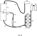
- Fig. 2A is a view illustrating a temperature control throttle device according to an embodiment of the present disclosure.
- the temperature control throttle device includes a throttle 203, a first pipeline 201 and a second pipeline 211, wherein the first pipeline 201 and the second pipeline 211 are connected to the same side of the throttle 203 in parallel in the air flow direction.
- the first pipeline 201 and the second pipeline 211 are positioned upstream of the throttle 203 in parallel.
- the second pipeline 211 is provided with a heat exchanger 212.
- the heat exchanger 212 may heat the air flowing through the second pipeline 211 with engine coolant, engine oil or engine exhaust gas as a heat source.
- the throttle 203 has a first inlet 202 connected to the first pipeline 201, a second inlet 213 connected to the second pipeline 211, and an outlet 205 connected to an engine air-intake manifold 206.
- the second pipeline 211 may be provided with a control device therein for changing a flow resistance characteristic, which will be described in detail later.
- the heat exchanger 212 when the heat exchanger 211 heats the air flowing through the second pipeline 211 with the engine coolant as the heat source, the heat exchanger 212 may be disposed in an engine cylinder block or in a water jacket of the engine cylinder head for cost saving. However, the heat exchanger 212 may also be disposed outside of the engine cylinder block as an independent heat exchanger. When the heat exchanger 211 heats the air flowing through the second pipeline 211 with the engine oil as the heat source, the heat exchanger 212 may be disposed in an oil sump or in an oil bypass pipeline.
- the heat exchanger 212 When the heat exchanger 211 heats the air flowing through the second pipeline 211 with the engine exhaust gas as the heat source, the heat exchanger 212 may be disposed after a main catalytic converter or disposed between a preliminary catalytic converter and the main catalytic converter.
- the engine intake air first passes through an air filter 200. Thereafter, the intake air is divided into two paths, passing through the first pipeline (also referred to as a conventional pipeline) 201 and the second pipeline (also referred to as a heating pipeline) 211, respectively.
- the intake air is not be specially heated, while in the heating pipeline 211, the intake air may be heated through the heat exchanger 212.
- the intake air in the conventional pipeline 201 enters the throttle 203 through the first inlet (also referred to as a first air inlet) 202 of the throttle 203, while the intake air in the heating pipeline 211 enters the throttle 203 through the second inlet (also referred to as an air inlet) 213 of the throttle.
- the normal temperature intake air entering from the first inlet 202 and the heated intake air entering from the second inlet 213 are selectively exhausted from the outlet 205 of the throttle, and then delivered to the engine 207 for combustion and doing work via a pipeline (e.g., the engine air-intake manifold 206) downstream of the throttle 203.
- Burned gas is exhausted through an exhaust pipeline 208 via a three-way catalytic converter (or other type of catalytic converter) 209 and a muffler 210. In this way, the temperature control of the intake air of the engine can be realized.
- Fig. 2B is a view illustrating a temperature control throttle device according to another embodiment of the present disclosure.
- the temperature control throttle device includes a throttle 253, and a first pipeline 264 and a second pipeline 262 connected to the same side of the throttle 253 in the air flow direction in parallel.
- the first pipeline 264 and the second pipeline 262 are located downstream of the throttle 253 in parallel and are connected to the engine air-intake manifold 256, respectively.
- the second pipeline 262 is provided with a heat exchanger 263.
- the heat exchanger 263 may heat the air flowing through the second pipeline 262 with engine coolant, engine oil or engine exhaust gas as a heat source.
- the throttle 253 has an air intake inlet 252, a first outlet 255 connected to the first pipeline 264, and a second outlet 261 connected to the second pipeline 262.
- the engine intake air enters from an air filter 250, connected to the throttle 253 through an intake pipeline 251, and enters the throttle 253 from the intake inlet 252.
- the gas entering the throttle 253 selectively enters the first pipeline 264 through the first outlet 255 or enters the second pipeline 262 (i.e., the heating pipeline) through the second outlet 261, thereby realizing temperature control of the intake air.
- the intake air of the first pipeline 264 and the intake air of the second pipeline 262 are merged into an air-intake manifold (e.g., the engine air-intake manifold 256) and then delivered to an engine 257 for combustion and doing work.
- Burned gas is exhausted through a gas exhaust pipeline 258 via a three-way catalytic converter (or other type of catalytic converter) 259 and a muffler 260.
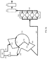
- Fig. 3A is a view illustrating a temperature control throttle device according to another embodiment of the present disclosure.
- a temperature control throttle device includes a throttle 330, a first pipeline 301 and a second pipeline 302, wherein the first pipeline 301 and the second pipeline 302 are connected to the same side of the throttle 330 in the air flow direction in parallel.
- the first pipeline 301 and the second pipeline 302 are located upstream of the throttle 330 in parallel.
- the second pipeline 302 is provided with a heat exchanger 306.
- the heat exchanger 306 may heat the air flowing through the second pipeline 302 with engine coolant, engine oil or engine exhaust gas as a heat source.
- the throttle 330 has a first inlet 303 connected to the first pipeline 301, a second inlet 304 connected to the second pipeline 302, and an outlet 305 connected to the engine air-intake manifold 309.
- the first inlet 303 and the second inlet 304 may be arranged physically adjacent to each other, and match with a valve body 310 of the throttle 330 in a planar surface or a curved surface (in the present embodiment, they match in the curved surface).
- the second inlet 304 is first opened, and as the valve body 310 continues to perform the motion in the planar surface or in the curved surface (in the preset embodiment, the motion is in the curved surface) beyond a first predetermined position, the first inlet 303 is opened.
- the second pipeline 302 may be provided therein with a control device for changing a thermal boundary of the air flowing through the pipeline.
- the heat exchanger 306 when the heat exchanger 306 heats the air flowing through the second pipeline 302 with the engine coolant as the heat source, the heat exchanger 306 may be disposed in an engine cylinder block or disposed in a water jacket of the engine cylinder head for cost saving. However, the heat exchanger 306 may also be disposed outside of the engine cylinder block as an independent heat exchanger. When the heat exchanger 306 heats the air flowing through the second pipeline 302 with the engine oil as the heat source, the heat exchanger 306 may be disposed in an oil sump or in an oil bypass pipeline.
- the heat exchanger 306 When the heat exchanger 306 heats the air flowing through the second pipeline 302 with the engine exhaust gas as the heat source, the heat exchanger 306 may be disposed after a main catalytic converter or disposed between a preliminary catalytic converter and the main catalytic converter.
- the engine intake air first passes through an air filter 300. Thereafter, the intake air is divided into two paths, passing through the first pipeline (also referred to as a conventional pipeline) 301 and the second pipeline (also referred to as a heating pipeline) 302, respectively.
- the intake air is not be specially heated, while in the heating pipeline 302, the intake air may be heated through the heat exchanger 306.
- the intake air in the conventional pipeline 301 enters the throttle 330 through the first inlet (also referred to as a first air inlet) 303 of the throttle 330, while the intake air in the heating pipeline 302 enters the throttle 330 through the second inlet (also referred to as an air inlet) 304 of the throttle 330.
- the valve body 310 of the throttle 330 forms sealing with the first inlet 303 and the second inlet 304.
- the normal temperature intake air entering from the first inlet 303 and heated intake air entering from the second inlet 304 are selectively exhausted from the outlet 305, and then delivered into an engine 321 through the pipeline (e.g., the engine air-intake manifold 309) downstream of the throttle 330 for combustion and doing work.
- Burned gas is exhausted through a gas exhaust pipeline 322 via a three-way catalytic converter (or other type of catalytic converter) 323 and a muffler 324. In this way, the temperature control of the intake air of the engine can be realized.
- the throttle 330 may be, for example, in a form of cylinder, and the first inlet 303, the second inlet 304, and the outlet 305 may be disposed on the side wall of the cylinder, wherein the first inlet 303 and the second inlet 304 are arranged physically adjacent to each other, and match with the valve body 310 in a curved surface.
- the cross-sectional area of the first inlet 303 may be bigger than that of the second inlet 304.
- either end of the valve body 310 may be provided with an optional blocking member.
- the blocking member may include a first blocking member 311 and a second blocking member 312.
- the blocking members may be in a close contact with a side wall of the throttle 330, thereby forming sealing with the side wall of the throttle 330.
- the blocking members of the valve body 310 block the first inlet 303 and the second inlet 304, thereby preventing air from passing through the throttle 330.
- the blocking of the blocking member to the second inlet 304 starts to be released, so that the second inlet 304 is opened.
- the blocking degree of the blocking members to the second inlet 304 gradually decreases, and the opening degree of the second inlet gradually increases until the second inlet is fully opened.
- the blocking of the blocking member to the second inlet 304 is fully released, so that the second inlet 304 is fully opened.
- the blocking of the blocking members to the first inlet 303 starts to be released, so that the first inlet 303 is opened.
- the blocking degree of the blocking members to the first inlet 303 gradually decreases, and the opening degree of the first inlet 303 gradually increases until the first inlet 303 is fully opened.
- valve body 310 continues to rotate beyond a second predetermined position, the blocking of the blocking member to the first inlet 303 is fully released, so that the first inlet 303 is fully opened.
- the blocking member may block the second inlet 304. This will be described in detail later with reference to Fig.4 .
- Fig. 3B is a view illustrating a temperature control throttle device according to another embodiment of the present disclosure.
- the temperature control throttle device includes a throttle 380, a first pipeline 351 and a second pipeline 352, wherein the first pipeline 351 and the second pipeline 352 are connected to the same side of the throttle 380 in the air flow direction in parallel.
- the first pipeline 351 and the second pipeline 352 are located downstream of the throttle 380 in parallel and are respectively connected to the engine air-intake manifold 359.
- the second pipeline 352 is provided with a heat exchanger 356.
- the heat exchanger 356 may heat the air flowing through the second pipeline 352 with engine coolant, engine oil or engine exhaust gas as a heat source.
- the throttle 380 has an inlet 355, a first outlet 353 connected to the first pipeline 351, and a second outlet 354 connected to the second pipeline 352.
- the first outlet 353 and the second outlet 354 may be arranged physically adjacent to each other, and match with a valve body 360 of the throttle 380 in a planar surface or a curved surface (in the present embodiment, they match in the curved surface).
- the second outlet 354 is first opened, and as the valve body 360 continues to perform the motion in the planar surface or in the curved surface (in the present embodiment, the motion is in the curved surface) beyond a first predetermined position, the first outlet 353 is opened. This will be described in detail later.
- the engine intake air enters from an air filter 350, connected to the throttle 380 through an intake pipeline 358, and enters the throttle 380 from the inlet 355.
- the gas entering the throttle 380 selectively enters the first pipeline 351 through the first outlet 353 or enters the second pipeline (i.e., the heating pipeline) 352 through the second outlet 354, thereby realizing temperature control of the intake air.
- the intake air in the first pipeline 351 and the intake air in the second pipeline 352 are merged into the air-intake manifold (e.g., the engine air-intake manifold 359) to be delivered to an engine 371 for combustion and doing work.
- Burned gas is exhausted through a gas exhaust pipeline 372 via a three-way catalytic converter (or other type of catalytic converter) 373 and a muffler 374.
- the throttle 380 may be, for example, in a form of cylinder, and the inlet 355, the first outlet 353 and the second outlet 354 may be disposed on the side wall of the cylinder, wherein the first outlet 353 and the second outlet 354 are arranged physically adjacent to each other and match with the valve body 360 in a curved surface.
- the cross-sectional area of the first outlet 353 may be bigger than that of the second outlet 354.
- either end of the valve body 360 may be provided with an optional blocking member.
- the blocking member may include a first blocking member 361 and a second blocking member 362. The blocking members may be in a close contact with a side wall of the throttle 380, thereby forming sealing with the side wall of the throttle 380.
- the blocking members of the valve body 360 block the first outlet 353 and the second outlet 354, thereby preventing air from passing through the throttle 380.
- the blocking of the blocking member to the second outlet 354 starts to be released, so that the second outlet 354 is opened.
- the blocking degree of the blocking members to the second outlet 354 gradually decreases, while the opening degree of the second outlet 354 gradually increases until the second outlet is fully opened. For example, as the valve body 360 continues to rotate beyond the first predetermined position, the blocking of the blocking member to the second outlet 354 is fully released, so that the second outlet 354 is fully opened.
- the blocking of the blocking member to the first outlet 353 starts to be released, so that the first outlet 353 is opened.
- the blocking degree of the blocking members to the first outlet 353 gradually decreases, and the opening degree of the first outlet 353 gradually increases until the first outlet is fully opened.
- the blocking of the blocking member to the first outlet 353 is fully released, so that the first outlet 353 is fully opened.
- the blocking member may block the second outlet 354.
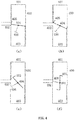
- Fig. 4 is a view illustrating working states of a temperature control throttle device according to an embodiment of the present disclosure.
- a throttle 400 includes a first inlet 401 connected the conventional pipeline, a second inlet 402 connected to the heating pipeline, and an outlet 403.
- two ends of a valve body 404 of the throttle 400 are provided with a first blocking member (also referred to as the first valve body fin) 405 and a second blocking member, respectively.
- the valve body 404 may also be provided with an optional extended member extending from the center of the valve body in a direction at a predetermined angle to the valve body (e.g., a direction perpendicular to the valve body, but not limited thereto), and a third blocking member (also referred to as the second valve body fin) 406 disposed at an end of the extended member.
- the (a), (b), (c) and (d) in Fig. 4 show working states of the temperature control throttle device corresponding to different loads of the engine, respectively.
- the (a) of Fig. 4 shows a working state of the throttle when the engine is idling
- the (b) of Fig. 4 shows a working state of the throttle when the engine load is low
- the (c) of Fig. 4 shows a working state of the throttle when the engine load is high
- the (d) of Fig. 4 shows a working state of the throttle when the engine is fully loaded.
- the valve body 404 when the engine is not working, the valve body 404 is in a horizontal state, and the first blocking member 405 and the second blocking member form sealing with two side walls of the throttle 400, thereby preventing air from passing through the throttle 400. Meanwhile, the first blocking member 405 also blocks the second inlet 402. Thereafter, as shown in (a) of Fig. 4 , when the engine enters an idle state, the valve body 404 starts to rotate. As the valve body 404 rotates, the blocking degree of the first blocking member 405 to the second inlet 402 gradually decreases, heated intake air starts to enter the throttle 400 through the opened second inlet 402, and enters the engine air-intake manifold through the outlet 403.
- the sealing formed between the first blocking member 405 and the second blocking member and the two side walls of the throttle 400 is maintained, and in this way, the intake air passing through the first inlet 401 is still blocked by the valve body 404.
- the valve body 404 when the engine enters a state of low load, the valve body 404 continues to rotate. As the valve body 404 rotates, the blocking degree of the first blocking member 405 to the second inlet 402 further decreases, more and more heated intake air enters the throttle 400 through the second inlet 402 of which the opening degree becomes bigger and bigger. That is to say, the first blocking member 405 may be used to control the air flow amount entering from the heating pipeline via the second inlet 402.
- valve body 404 rotates over a predetermined threshold angle, the sealing between the first blocking member 405 and the second blocking member and two side walls of the throttle 400 is released, unheated intake air may enter the throttle 400 through the first inlet 401, and intake air temperature starts to decrease.
- intake air temperature starts to decrease.
- the valve body 404 continues to rotate. As the valve body 404 rotates, more and more unheated intake air enters the throttle 400 through the first inlet 401. In particular, since the first inlet 401 is far bigger than the second inlet 402, the ratio of the unheated intake air in the intake air passing through the outlet 403 becomes higher and higher.
- the valve body 404 rotates 90 degrees, and the unheated intake air passes through the outlet 403 without any blocking. At this time, the ratio of heated intake air in the intake air passing through the outlet 403 may be negligible.
- the third blocking member 406 when the valve body 404 rotates 90 degrees, the third blocking member 406 may block the second inlet 402, and the heated intake air does not enter the throttle 400 through the second inlet 402, which ensures that the engine intake air temperature at this time is the same as that in the conventional state, and there will be no extra knocking burden.
- Fig. 5 is a view illustrating working states of a temperature control throttle device according to an example not being part of the present disclosure.
- the temperature control throttle device may include a first throttle and a second throttle.
- the first pipeline or conventional pipeline 511 and the second pipeline or heating pipeline 512 are connected to the same side of the first throttle and the second throttle in the air flow direction (at the upstream of the first throttle and the second throttle, as shown in Fig.5 ) in parallel, and the second pipeline 512 is provided with a heat exchanger (not shown).
- a valve body 503 of the first throttle and a valve body 504 of the second throttle may have a fixed motion relationship. That is to say, the valve body 503 and the valve body 504 have a definite mechanical correlation, so that they can be driven by one actuator. Alternatively, the valve body 503 and the valve body 504 may also be driven by two actuators, respectively. This will be described in detail below with reference to Fig. 5 .
- the (a), (b), (c) and (d) of Fig. 5 show working states of the temperature control throttle device corresponding to different loads of the engine, respectively.
- the (a) of Fig. 5 shows a working state of the throttle when the engine is idling
- the (b) of Fig. 5 shows a working state of the throttle when the engine load is low
- the (c) of Fig. 5 shows a working state of the throttle when the engine load is high
- the (d) of Fig. 5 shows a working state of the throttle when the engine is fully loaded.
- the valve body 504 when the engine enters idling, the valve body 504 first rotates while the valve body 503 remains stationary.
- Heated intake air enters the second throttle through the second inlet 502, and enters an engine air-intake manifold 505 through the second throttle, while unheated air is blocked by the valve body 503 and cannot pass through the first throttle.
- the valve body 504 when the engine enters a state of low load, the valve body 504 continues to rotate up to 90 degrees, more and more heated intake air passes through the second throttle. Thereafter, as the valve body 504 rotates over 90 degrees, the valve body 503 starts to rotate.
- valve body 504 when the engine enters a state of high load, as the valve body 504 rotates over 90 degrees, the valve body 503 starts to rotate, so that unheated intake air enters the first throttle through the first inlet 501, and enters the engine air-intake manifold 505 through the first throttle, while less and less heated air passes through the second throttle.
- the valve body 504 rotates 180 degrees to fully block the second throttle, so that the second throttle is closed, and the heated air is blocked by the valve body 504 and no longer passes through the second throttle.
- valve body 503 rotates to 90 degrees, the first throttle is fully opened, and unheated intake air enters the engine air-intake manifold 505 through the first throttle without any blocking. In this way, it is ensured that any air does not enter from the heating pipeline when the engine is fully loaded, and thereby ensuring that the engine intake air temperature is the same as that in the conventional state, and there will be no extra knocking burden.
- the positional relationship of two valve bodies obviously may realize a maximum flexibility, thereby realizing a maximum flexibility of temperature control.
- Fig. 6 is a view illustrating an example of changing a flow resistance characteristic by a temperature control throttle device according to an embodiment of the present disclosure.
- the example of changing the flow resistance characteristic shown in Fig. 6 is based on the temperature control throttle device shown in Fig. 4 .
- the heating pipeline is connected to the second inlet (an air inlet) 602 as shown in (b) of Fig. 6 , wherein the rectangle formed by thick solid lines is the second inlet 602. Since the valve body of the throttle partially blocks the intake air, a part of the area of the air inlet may effectively intake air, that is, a blank area not covered by the shadow shown in (b) of Fig. 6 is the area that can effectively intake air, while the shadow area is the area covered by the valve body (particularly, the second blocking member on the valve body).
- Reference numeral 605 indicates a slider that can slide left and right in the heating pipeline.
- the slider 605 may be made of stainless steel or other wear resistant materials, but is not limited thereto.
- Fig. 7 is a view illustrating working states of a temperature control throttle device according to an embodiment of the present disclosure.
- a throttle 730 comprises a first inlet 703 connected to the conventional pipeline (i.e., the first pipeline), a second inlet 704 connected to the heating pipeline (i.e., the second pipeline), and an outlet 705.
- a valve body 710 of the throttle 730 are provided with an optional first blocking member (also referred to as the first valve body fin) 704 and an optional second blocking member (also referred to as the second valve body fin) 712, respectively.
- the throttle 730 may be, for example, in a form of cylinder, and the first inlet 703, the second inlet 704, and the outlet 705 may be disposed on a side wall of the cylinder, and the first inlet 703 and the second inlet 704 may be arranged physically adjacent to each other and match with the valve body 710 in a curved surface.
- the valve body 710 may be in an irregular L shape, i.e., the angle between two wings of the L shape may not be an exact right angle, but may be, for example, an obtuse angle greater than 90 degrees.
- the (a), (b), (c) and (d) of Fig. 7 show working states of the temperature control throttle device corresponding to different loads of the engine, respectively.
- the (a) of Fig. 7 shows a working state of the throttle when the engine is idling
- the (b) of Fig. 7 shows a working state of the throttle when the engine load is low
- the (c) of Fig. 7 shows a working state of the throttle when the engine load is high
- the (d) of Fig. 7 shows a working state of the throttle when the engine is fully loaded.
- the first blocking member 711 and the second blocking member 712 of the valve body 710 form sealing with the side wall of the throttle 730, thereby preventing air from passing through the throttle 730.
- the first blocking member 711 may block the first inlet 703 and the second inlet 704. Thereafter, when the engine enters an idle state as shown in (a) of Fig. 7 , the valve body 710 starts to rotate. As the valve body 710 rotates, the blocking degree of the first blocking member 711 to the second inlet 704 gradually decreases, and heated intake air starts to enter the throttle 730 through the opened second inlet 704, and enter the engine air-intake manifold through the outlet 705. Meanwhile, the blocking of the first blocking member 711 to the first inlet 703 is maintained, and in this way, intake air passing through the first inlet 703 is still blocked by the value body 710 (i.e., the first blocking member 711). As shown in (b) of Fig.
- the valve body 710 when engine enters a state of low load, the valve body 710 continues to rotate. As the valve body 710 rotates, the blocking degree of the first blocking member 711 to the second inlet 704 further decreases until the blocking to the second inlet 704 is fully released, and more and more heated intake air enters the throttle 730 through the second inlet 704 of which the opening degree becomes bigger and bigger. That is to say, the first blocking member 711 may be used to control the air flow amount entering throttle 730 from the heating pipeline through the second inlet 704.
- valve body 710 rotates over a predetermined threshold angle (i.e., when the valve body 710 rotates beyond a first predetermined position), the blocking of the first blocking member 711 to the first inlet 703 starts to be released, and unheated intake air may enter the throttle 730 through the first inlet 703, so that intake air temperature starts to decrease.
- a predetermined threshold angle i.e., when the valve body 710 rotates beyond a first predetermined position
- the blocking of the first blocking member 711 to the first inlet 703 starts to be released, and unheated intake air may enter the throttle 730 through the first inlet 703, so that intake air temperature starts to decrease.
- the valve body 710 continues to rotate. As the valve body 710 rotates, more and more unheated intake air enters the throttle 730 through the first inlet 703.
- the second blocking member 712 when the blocking of the first blocking member 711 to the first inlet 703 starts to be released, the second blocking member 712 starts to block the second inlet 704.
- the cross-sectional area of the first inlet 703 is far bigger than that of the second inlet 704, while there is no heat exchanger in the first pipeline, the flow resistance in the first pipeline is lower than that in the second pipeline, and the ratio of the unheated intake air in the intake air passing through the outlet 705 becomes higher and higher.
- the valve body 710 when the engine enters a state of full load, the valve body 710 rotates to completely open the first inlet 703, and unheated intake air passes through the outlet 705 without any blocking.
- the ratio of heated intake air in the intake air passing through the outlet 705 may be negligible.
- the second blocking member 712 when the valve body 710 rotates beyond the second predetermined position (e.g., when the valve body 710 rotates to fully open the first inlet 703, but not limited thereto), the second blocking member 712 may fully block the second inlet 704, and in this way, the heated intake air does not enter the throttle 730 through the second inlet 704, which ensures that the engine intake air temperature is the same as that in the conventional state, and there will be no extra knocking burden.
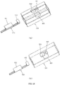
- Fig. 8 is a perspective view illustrating a part of the temperature control throttle device according to an embodiment of the present disclosure.
- the throttle 730 is in a form of cylinder
- the first inlet 703, the second inlet 704, and the outlet 705 may be disposed on a side wall of the cylinder, and penetrate through the side wall of the cylinder.
- the first inlet 703 and the second inlet 704 are arranged physically adjacent to each other, and match with the valve body 710 of the throttle 730 in a cured surface, and as the valve body 710 performs a motion in the curved surface, the second inlet 704 and the first inlet 703 may be opened in sequence.
- the first blocking member 711 and the second blocking member 712 form sealing with the side wall (specifically speaking, an inner wall) of the throttle 730.
- the first blocking member 711 may block the first inlet 703 and the second inlet 704.
- the blocking of the first blocking member 711 to the second inlet 704 is released while the blocking to the first inlet 703 is maintained, that is, the second inlet 704 starts to be opened while the first inlet 703 maintains being closed.
- the blocking of the first blocking member 711 to the second inlet 704 may be fully released, that is, the second inlet 704 may be fully opened.
- the blocking of the first blocking member 711 to the first inlet 703 starts to be released, that is, the first inlet 703 starts to be opened.
- the blocking of the first blocking member 711 to the first inlet 703 may be fully released, that is, the first inlet 703 may be fully opened. Meanwhile, when the valve body 710 rotates beyond the second predetermined position (e.g., when the blocking of the first blocking member 711 to the first inlet 703 is fully released, but not limited thereto), the second blocking member 712 may block the second inlet 704.
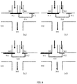
- Fig. 9 is a view illustrating working states of a temperature control throttle device according to another embodiment of the present disclosure.
- a throttle 930 comprises a first inlet 903 connected the conventional pipeline (i.e., the first pipeline), a second inlet 904 connected to the heating pipeline (i.e., the second pipeline), and an outlet 905.
- a valve body 910 of the throttle 930 are provided with an optional first blocking member (also referred to as the first valve body fin) 911 and an optional second blocking member (also referred to as the second valve body fin) 912, respectively.
- the throttle 930 may be, for example, in a form of cuboid
- the first inlet 903, the second inlet 904, and the outlet 905 may be disposed on two different side walls (e.g., two opposing side walls) of the cuboid, respectively, and the first inlet 903 and the second inlet 904 may be arranged physically adjacent to each other and match with the valve body 910 in a planar surface.
- the valve body 910 may be U-shaped or in a shape corresponding to the Chinese character of " ".
- the (a), (b), (c) and (d) of Fig. 9 show working states of the temperature control throttle device corresponding to different loads of the engine, respectively.
- the (a) of Fig. 9 shows a working state of the throttle when the engine is idling
- the (b) of Fig. 9 shows a working state of the throttle when the engine load is low
- the (c) of Fig. 9 shows a working state of the throttle when the engine load is high
- the (d) of Fig. 9 shows a working state of the throttle when the engine is fully loaded.
- the first blocking member 911 and the second blocking member 912 of the valve body 910 form sealing with the side wall of the throttle 930, thereby preventing air from passing through the throttle 930.
- the first blocking member 911 may block the first inlet 903 and the second inlet 904. Thereafter, as shown in (a) of Fig. 9 , when the engine enters an idle state, the valve body 910 starts to move (or translate). As the valve body 910 moves, the blocking degree of the first blocking member 911 to the second inlet 904 gradually decreases, the heated intake air starts to enter the throttle 930 through the opened second inlet 904, and enter the engine air-intake manifold via the outlet 905. Meanwhile, the blocking of the first blocking member 911 to the first inlet 903 is maintained, in this way, intake air passing through the first inlet 903 is still blocked by the valve body 910 (i.e., the first blocking member 911). As shown in (b) of Fig.
- the valve body 910 when the engine enters a state of low load, the valve body 910 continues to move. As the valve body 910 moves, the blocking degree of the first blocking member 911 to the second inlet 904 further decreases until the blocking to the second inlet 904 is fully released, more and more heated intake air enters the throttle 930 through the second inlet 904 of which the opening degree becomes bigger and bigger. That is to say, the first blocking member 911 may be used to control the air flow amount entering the throttle 930 from the heating pipeline through the second inlet 904.
- valve body 910 moves beyond a first predetermined position, the blocking of the first blocking member 911 to the first inlet 903 starts to be released, unheated intake air may enter the throttle 930 through the first inlet 903, and intake air temperature starts to decrease.
- intake air temperature starts to decrease.
- the valve body 910 continues to move. As the valve body 910 moves, more and more unheated intake air enters the throttle 930 through the first inlet 903.
- the second blocking member 912 when the blocking of the first blocking member 911 to the first inlet 903 starts to be released, the second blocking member 912 starts to block the second inlet 904.
- the flow resistance in the first pipeline is lower than that in the second pipeline, so that the ratio of the unheated intake air in the intake air passing through the outlet 905 becomes higher and higher.
- the valve body 910 moves to completely open the first inlet 903, and unheated intake air passes through the outlet 905 without any blocking. Meanwhile, the ratio of heated intake air in the intake air passing through the outlet 905 may be negligible.
- the second blocking member 912 when the valve body 910 moves beyond the second predetermined position (e.g., when the valve body 910 moves to fully open the first inlet 903), the second blocking member 912 may fully block the second inlet 904, and in this way, the heated intake air does not enter the throttle 930 through the second inlet 904 so as to ensure that the engine intake air temperature is the same as that in the conventional state, and there will be no extra knocking burden.
- Fig. 10 is a perspective view illustrating a part of a temperature control throttle device according to another embodiment of the present disclosure.
- the throttle 930 is in a cuboid shape
- the first inlet 903, the second inlet 904, and the outlet 905 may be disposed on a side wall of the cuboid, and penetrate through the side walls of the cuboid.
- the first inlet 903, the second inlet 904, and the outlet 905 may be disposed on two different side walls (e.g., two opposing side walls) of the cuboid, respectively, and penetrate through the side walls of the cuboid.
- the first inlet 903 and the second inlet 904 may be arranged physically adjacent to each other, and match with the valve body 910 in a planar or curved surface, and as the valve body 910 performs a motion in the planar or curved surface, the second inlet 904 and the first inlet 903 may be opened in sequence.
- the first blocking member 911 and the second blocking member 912 form sealing with the side wall (specifically speaking, an inner wall) of the throttle 930.
- the inner walls of the throttle 930 are planar surfaces
- the inner walls of the throttle 930 are curved surfaces.
- the first blocking member 911 may block the first inlet 903 and the second inlet 904.
- the blocking of the first blocking member 911 to the second inlet 904 starts to be released while the blocking to the first inlet 903 is maintained, that is, the second inlet 904 starts to be opened while the first inlet 903 maintains being closed.
- the blocking of the first blocking member 911 to the second inlet 904 may be fully released, that is, the second inlet 904 may be fully opened.
- the blocking of the first blocking member 911 to the first inlet 903 starts to be released, that is, the first inlet 903 starts to be opened.
- the blocking of the first blocking member 911 to the first inlet 903 may be fully released, that is, the first inlet 903 may be fully opened.
- the second blocking member 912 may block the second inlet 904.
- Fig. 11 is a view illustrating working states of a temperature control throttle device according to another embodiment of the present disclosure.
- the temperature control throttle device may include a first throttle 1130 and a second throttle 1120 connected in series.
- the first pipeline (conventional pipeline) 1101 and the second pipeline (heating pipeline) 1102 are connected to the same side of the first throttle 1130 in the air flow direction in parallel (at the upstream of the first throttle 1130 as shown in Fig.11 ), and the second pipeline 1102 is provided with a heat exchanger (not shown).
- the first throttle 1130 has a first inlet 1103 connected to the first pipeline 1101, a second inlet 1104 connected to the second pipeline 1102 and an outlet 1105.
- the second throttle 1120 is located downstream of the first throttle 1130 and have an inlet 1121 connected to the outlet 1105 of the first throttle 1130 through an intermediate pipeline 1107 and an outlet 1122 connected to the engine air-intake manifold.
- the first throttle 1130 selectively receives air flowing through the first pipeline 1101 or the second pipeline 1102.
- two ends of a valve body 1110 of the first throttle 1130 are provided with a first blocking member (also referred to as the first valve body fin) 1111 and a second blocking member, respectively.
- the valve body 1110 may further be provided with an optional extended member connected to the valve body and extending in a direction at a predetermined angle to the valve body (e.g., a direction perpendicular to the valve body, but not limited thereto) and an optional third blocking member (also referred to as the second valve body fin) 1113 disposed at an end of the extended member.
- the valve body 1110 of the first throttle 1130 when the engine is not working, the valve body 1110 of the first throttle 1130 is in a horizontal state, the first blocking member 1111 and the second blocking member form sealing with two side walls of the first throttle 1130, thereby preventing air from passing through the first throttle 1130. Meanwhile, the first blocking member 1111 also blocks the second inlet 1104.
- the valve body 1110 starts to rotate. As the valve body 1110 rotates, the blocking degree of the first blocking member 1111 to the second inlet 1104 gradually decreases, heated intake air starts to enter the first throttle 1130 through the opened second inlet 1104, enters the intermediate pipeline 1107 through the outlet 1105, and then enters the second throttle 1120 through the inlet 1121 of the second throttle 1120.
- the ratio of the unheated intake air in the intake air discharged to the second throttle 1120 through the outlet 1105 becomes higher and higher.
- the valve body 1110 continues to rotate beyond the second predetermined position (e.g., when the valve body 1110 rotates 90 degrees)
- unheated intake air passes through the outlet 1105 without any blocking.
- the ratio of heated intake air in the intake air passing through the outlet 1105 may be negligible.
- the third blocking member 1113 may block the second inlet 1104, the heated intake air does not enter the first throttle 1130 through the second inlet 1104 so as to ensure that the engine intake air temperature is the same as that in the conventional state, and there will be no extra knocking burden.
- the flow amount of the air discharged from the outlet 1122 may be controlled by adjusting the rotation degree of the valve body 1140 of the second throttle 1120, thereby realizing the control of the air flow amount entering the engine.
- the first throttle 1130 is used to control the ratio between the heated air and the unheated air, and thus any valve body that may realize the above purpose is applicable to the first throttle 1130.
- the second throttle 1120 is used to control the air flow amount entering the engine, which may be implemented by a conventional throttle. Alternatively, the second throttle 1120 may also be located upstream of the first throttle 1130.
- the second throttle may include a first inlet connected to the first pipeline, a second inlet connected to the second pipeline, and an outlet connected to the engine air-intake manifold.
- the first throttle may be used to selectively make air flow through the first pipeline or the second pipeline, and the second throttle may be used to control the air flow amount entering the engine.
- the second throttle may also be located upstream of the first throttle.
- the second throttle may be located upstream of the first throttle and used to control the air flow amount entering the first pipeline and the second pipeline when the first pipeline and the second pipeline are located upstream of the first throttle, or used to control the air flow amount entering the first throttle when the first pipeline and the second pipeline are located downstream of the first throttle.
- Fig. 12 is a view illustrating a temperature control throttle device according to another embodiment of the present disclosure.
- the temperature control throttle device includes a throttle 1200, a first pipeline 1201 and a second pipeline 1202, wherein the first pipeline 1201 and the second pipeline 1202 are connected to the same side of the throttle 1200 in the air flow direction in parallel.
- the first pipeline 1201 and the second pipeline 1202 may be located upstream of the throttle 1200 in parallel.
- the second pipeline 1202 is provided with a heat exchanger including a first heat exchanger 1206 and a second heat exchanger 1207 connected in series.
- the heat source of the first heat exchanger 1206 may be the engine exhaust gas
- the heat source of the second heat exchanger 1207 may be the engine coolant.
- the throttle 1200 further has a first inlet 1203 connected to the first pipeline 1201, a second inlet 1204 connected to the second pipeline 1202, and an outlet 1205 connected to the engine air-intake manifold 1209.
- the first inlet 1203 and the second inlet 1204 may be arranged physically adjacent to each other, and match with a valve body 1210 of the throttle 1200 in a planar surface or in a curved surface (in the present embodiment, they match in the curved surface).
- the second inlet 1204 is first opened, and as the valve body 1210 continues to perform the motion in the planar surface or in the curved surface (in the present embodiment, the motion is in the curved surface) beyond a first predetermined position, the first inlet 1203 is opened.
- the second pipeline 1202 is further provided with a control valve 1208 and a bypass pipeline 1221.
- the control valve 1208 is disposed upstream of the first heat exchanger 1206, and one end of the bypass pipeline 1221 is connected to the control valve 1208 and the other end thereof is connected to the downstream of the first heat exchanger 1206.
- the other end of the bypass pipeline may be connected between the first heat exchanger and the second heat exchanger.
- the present disclosure is not limited to this.
- the bypass pipeline 1221 may be disabled, so that the first heat exchanger 1206 is enabled. Meanwhile, the second heat exchanger 1207 is also enabled.
- the bypass pipeline 1221 may be enabled, so that the first heat exchanger 1206 is disabled, and only the second heat exchanger 1207 is enabled. In this way, through the actuation of the control valve 1208, the thermal boundary of the second pipeline 1202 may be remarkably changed.
- the air flowing through the second pipeline 1202 can be heated using all the heat sources of the engine as much as possible. Meanwhile, the air flowing through the first heat exchanger 1206 may also flow through the second heat exchanger 1207. In this way, it can ensure that the temperature of the air finally entering the engine is always near the temperature of the engine coolant, preventing abnormal combustion caused by the intake air of excessively high temperature entering the engine.
- valve body 1210 of the throttle 1200 has a first blocking member 1211 and a second blocking member 1212, and they may be in a close contact with the side wall of the throttle 1200, thereby forming sealing with the side wall of the throttle 1200. Since the working principle of the throttle 1200 shown in Fig. 12 is the same as that of the throttle 330 shown in Fig. 3A , and the temperature control throttle shown in Fig. 12 may have the working states of the temperature control throttle shown in Fig. 10 , the description thereof is not repeatedly described here.
- Fig. 13 is a view illustrating a temperature control throttle device according to another embodiment of the present disclosure.
- the temperature control throttle device includes a throttle 1300, a first pipeline 1301 and a second pipeline 1302, wherein the first pipeline 1301 and the second pipeline 1302 are connected to the same side of the throttle 1300 in the air flow direction in parallel.
- the first pipeline 1301 and the second pipeline 1302 may be located upstream of the throttle 1300 in parallel.
- the second pipeline 1302 is provided with a heat exchanger 1306.
- the heat source of the heat exchanger 1306 may be the engine coolant.
- the heat source of the heat exchanger 1306 may also be both of the engine exhaust gas and the engine coolant, and the heat source of the heat exchanger 1306 may be switched between the engine exhaust gas and the engine coolant, thereby only one of the engine exhaust gas and the engine coolant being used as the heat source.
- the throttle 1300 further has a first inlet 1303 connected to the first pipeline 1301, a second inlet 1304 connected to the second pipeline 1302, and an outlet 1305 connected to the engine air-intake manifold 1309.
- the first inlet 1303 and the second inlet 1304 may be arranged physically adjacent to each other, and match with a valve body 1310 of the throttle 1300 in a planar or curved surface (in the present embodiment, they match in the curved surface).
- the second inlet 1304 is first opened, and as the valve body 1310 continues to perform the motion in the planar or curved surface (in the preset embodiment, the motion is in the curved surface) beyond a first predetermined position, the first inlet 1303 is opened.
- the temperature control throttle device further includes a third pipeline 1308 and an air valve 1307 disposed in the third pipeline 1308.
- One end of the third pipeline 1308 is connected between the heat exchanger 1306 and the second inlet 1304, and the other end of the third pipeline 1308 is connected to the downstream of the outlet 1305.
- the air valve 1307 is closed, the third pipeline 1308 is disabled, and when the air valve 1307 is opened, the third pipeline 1308 is enabled.
- the temperature control throttle shown in Fig. 13 is completely the same as the temperature control throttle shown in Fig. 3A .
- the minimum flow resistance in the second pipeline 302 is determined by the cross-sectional area of the inlet 304 of the throttle 330.
- Fig. 3A the minimum flow resistance in the second pipeline 302 is determined by the cross-sectional area of the inlet 304 of the throttle 330.
- Fig. 3A the minimum flow resistance in the second pipeline 302 is determined by the cross-sectional area of the inlet 304 of the throttle 330.
- the cross-sectional area of the inlet formed by the other end of the third pipeline 1308 at the downstream of the outlet 1305 is bigger than that of the second inlet 1304.
- the air valve 1307 when the air valve 1307 is fully opened, while the first inlet 1303 is fully closed (the second inlet 1304 may be of any opened degree), intake air of the engine has barely any resistance. Meanwhile, all of the intake air is heated by the heat exchanger 1306.
- the engine can work in a Homogeneous Charge Compression Ignition (HCCI) state.
- HCCI Homogeneous Charge Compression Ignition
- the intake air temperature One factor that hinders the HCCI state expanding to the state of low load is the intake air temperature.
- the engine needs to work in various environments, e.g., in an environment of high cold, where the temperature may be as low as minus 40 to 50°C; while under an extremely hot condition, the temperature may exceed 50°C, and the difference of intake air temperature between the two conditions is huge, which brings great difficulty to the control and application of HCCI.
- the temperature control throttle device as shown in Fig. 13 , the intake air having a temperature close to that of the engine coolant can be obtained all the time, and a switching between the HCCI and the conventional engine working states can be quickly switched by the air valve 1307.
- the thermal boundary, pressure boundary and response speed of the control may be simultaneously ensured.
- valve body 1310 of the throttle 1300 has a first blocking member 1311 and a second blocking member 1312, and they may be in a close contact with the side wall of the throttle 1300, thereby forming sealing with the side wall of the throttle 1300. Since the working principle of the throttle 1300 shown in Fig. 13 is the same as that of the throttle 330 shown in Fig. 3A , and the temperature control throttle shown in Fig. 13 may have the same working states of the temperature control throttle shown in Fig. 7 , the description thereof is not repeatedly described here.
- one end of the third pipeline may be connected to the upstream of the inlet 1302, and the other end of the third pipeline may be connected between the heat exchanger 1309 and the second outlet 1305.
- the air valve disposed in the third pipeline is closed, the third pipeline is disabled, and when the air valve is opened, the third pipeline is enabled.
- temperature control of the engine may be realized; intake air heating may be provided when the engine load is low, pumping loss of the engine may be reduced and the oil and gas mixing may be improved, thereby improving oil consumption and reducing emissions; and meanwhile, when the engine is fully loaded, the original intake air temperature may be maintained to ensure that the engine's full load combustion characteristic and performance are not affected.
- temperature control is realized by directly controlling the air, there is almost no delay in temperature change, thermal inertia does not exist, and complexity of control is reduced.
Description
- The present disclosure relates to a field of air intake control of an engine, and more particularly, to a temperature control throttle device that can control an intake air temperature of an engine.
- Generally speaking, spark-ignition engines, at least including a spark-ignition gasoline engine and a spark-ignition natural gas engine, employ a throttle to control an air intake amount of engine to control an engine load.
-
Fig. 1 is a view illustrating an existing spark-ignition engine throttle and an air intake pipeline. As shown inFig. 1 , engine intake air enters from anair filter 100 connected to athrottle 103 through apipeline 101, and then enters thethrottle 103 from athrottle inlet 102. According to load requirements of the engine, athrottle valve body 104 rotates to adjust an air flow amount entering the engine through thethrottle 103. The intake air enters anengine 107 for combustion and doing work via athrottle outlet 105 and anintake pipeline 106 downstream of the throttle. Burned gas is exhausted through anexhaust pipeline 108 via a three-way catalytic converter (or other type of catalytic converter) 109 and amuffler 110. - It can be seen from
Fig. 1 that the existing throttle implementation scheme can control the air intake amount of the engine, however, under different intake air amounts, the heat exchange condition for the intake air is constant, and is generally close to an ambient temperature. Therefore, in the case of low temperature and low load, neither the fuel economy nor engine emissions can be effectively ensured. -
EP 1 136 675 A2 discloses an air-fuel charge controller for a homogenous-charge compression-ignition engine. -
US 2015/275828 A1 discloses an air intake assembly for a vehicle. -
US 8 539 932 B2 discloses systems and methods for heating intake air during cold HCCI operation. - In view of the working principle of spark-ignition engines, the tendency of engine knocking is extremely slight when the load is low, and thus, properly increasing the engine intake air temperature does not cause knocking, while it may reduce pumping loss, improve oil and gas premixing, and accelerate combustion velocity. When the load is high, the intake air temperature should be lower to suppress knocking and ensure normal combustion.
- Thus, on one hand, the present disclosure aims to solve the problem of how to control the intake air temperature of the engine under different loads in a reliable and low-cost manner.
- According to an aspect of the present disclosure, there is provided a temperature control throttle device according to claim 1.
- According to another aspect of the present disclosure, there is provided a temperature control throttle device according to claim 2.
- With the temperature control throttle device according to the embodiments of the present disclosure, temperature control of the engine may be realized; intake air heating may be provided when the engine load is low, which may reduce gas pumping power of the engine and improve the oil and gas mixing, thereby improving oil consumption and reducing emissions; and meanwhile, when the engine is fully loaded, the original intake air temperature may be maintained to ensure that the engine's full load combustion characteristic and performance are not affected. In addition, since the temperature control is realized by directly controlling the air, there is almost no delay in temperature change, thermal inertia does not exist, and complexity of control is reduced.
- Those of ordinary skill in the art may better understand the inventive concept of the present disclosure from the description taken in conjunction with the following drawings, wherein:
-
Fig. 1 is a view illustrating an existing spark-ignition engine throttle and an intake pipeline; -
Fig. 2A is a view illustrating a temperature control throttle device according to an embodiment of the present disclosure; -
Fig. 2B is a view illustrating a temperature control throttle device according to another embodiment of the present disclosure; -
Fig. 3A is a view illustrating a temperature control throttle device according to still another embodiment of the present disclosure; -
Fig. 3B is a view illustrating a temperature control throttle device according to yet another embodiment of the present disclosure; -
Fig. 4 is a view illustrating working states of a temperature control throttle device according to an embodiment of the present disclosure; -
Fig. 5 is a view illustrating working states of a temperature control throttle device according to an example not being part of the present disclosure; -
Fig. 6 is a view illustrating an example of changing a flow resistance characteristic by a temperature control throttle device according to an embodiment of the present disclosure; -
Fig. 7 is a view illustrating working states of a temperature control throttle device according to an embodiment of the present disclosure; -
Fig. 8 is a perspective view illustrating a local part of a temperature control throttle device according to an embodiment of the present disclosure; -
Fig. 9 is a view illustrating working states of a temperature control throttle device according to another embodiment of the present disclosure; -
Fig. 10 is a perspective view illustrating a part of a temperature control throttle device according to another embodiment of the present disclosure; -
Fig. 11 is a view illustrating working states of a temperature control throttle device according to another embodiment of the present disclosure; -
Fig. 12 is a view illustrating a temperature control throttle device according to another embodiment of the present disclosure; -
Fig. 13 is a view illustrating a temperature control throttle device according to another embodiment of the present disclosure. - Hereinafter, the present disclosure is described more sufficiently with reference to the drawings in which the exemplary embodiments of the present disclosure are illustrated. However, the present disclosure may be implemented in many different manners and should not be interpreted to be limited to the embodiments proposed hereby. Rather, these exemplary embodiments are provided to allow the present disclosure to be complete and thorough, and sufficiently convey the scope of the present disclosure to those skilled in the art.
- According to the embodiments of the present disclosure, engines that may employ the temperature control throttle device of the present disclosure include, but not limited to: engines with natural air intake forms, turbocharged engines or supercharged engines of other forms, spark-ignition engines, compression-ignition engines, and the like.
-
Fig. 2A is a view illustrating a temperature control throttle device according to an embodiment of the present disclosure. - Referring to
Fig. 2A , the temperature control throttle device includes athrottle 203, afirst pipeline 201 and asecond pipeline 211, wherein thefirst pipeline 201 and thesecond pipeline 211 are connected to the same side of thethrottle 203 in parallel in the air flow direction. InFig. 2A , thefirst pipeline 201 and thesecond pipeline 211 are positioned upstream of thethrottle 203 in parallel. Thesecond pipeline 211 is provided with aheat exchanger 212. Theheat exchanger 212 may heat the air flowing through thesecond pipeline 211 with engine coolant, engine oil or engine exhaust gas as a heat source. In addition, thethrottle 203 has afirst inlet 202 connected to thefirst pipeline 201, asecond inlet 213 connected to thesecond pipeline 211, and anoutlet 205 connected to an engine air-intake manifold 206. Alternatively, thesecond pipeline 211 may be provided with a control device therein for changing a flow resistance characteristic, which will be described in detail later. - Here, when the
heat exchanger 211 heats the air flowing through thesecond pipeline 211 with the engine coolant as the heat source, theheat exchanger 212 may be disposed in an engine cylinder block or in a water jacket of the engine cylinder head for cost saving. However, theheat exchanger 212 may also be disposed outside of the engine cylinder block as an independent heat exchanger. When theheat exchanger 211 heats the air flowing through thesecond pipeline 211 with the engine oil as the heat source, theheat exchanger 212 may be disposed in an oil sump or in an oil bypass pipeline. When theheat exchanger 211 heats the air flowing through thesecond pipeline 211 with the engine exhaust gas as the heat source, theheat exchanger 212 may be disposed after a main catalytic converter or disposed between a preliminary catalytic converter and the main catalytic converter. - During working, the engine intake air first passes through an
air filter 200. Thereafter, the intake air is divided into two paths, passing through the first pipeline (also referred to as a conventional pipeline) 201 and the second pipeline (also referred to as a heating pipeline) 211, respectively. In theconventional pipeline 201, the intake air is not be specially heated, while in theheating pipeline 211, the intake air may be heated through theheat exchanger 212. The intake air in theconventional pipeline 201 enters thethrottle 203 through the first inlet (also referred to as a first air inlet) 202 of thethrottle 203, while the intake air in theheating pipeline 211 enters thethrottle 203 through the second inlet (also referred to as an air inlet) 213 of the throttle. Through a position control of thethrottle valve body 204, the normal temperature intake air entering from thefirst inlet 202 and the heated intake air entering from thesecond inlet 213 are selectively exhausted from theoutlet 205 of the throttle, and then delivered to theengine 207 for combustion and doing work via a pipeline (e.g., the engine air-intake manifold 206) downstream of thethrottle 203. Burned gas is exhausted through anexhaust pipeline 208 via a three-way catalytic converter (or other type of catalytic converter) 209 and amuffler 210. In this way, the temperature control of the intake air of the engine can be realized. -
Fig. 2B is a view illustrating a temperature control throttle device according to another embodiment of the present disclosure. - Referring to
Fig. 2B , the temperature control throttle device includes athrottle 253, and afirst pipeline 264 and asecond pipeline 262 connected to the same side of thethrottle 253 in the air flow direction in parallel. InFig. 2B , thefirst pipeline 264 and thesecond pipeline 262 are located downstream of thethrottle 253 in parallel and are connected to the engine air-intake manifold 256, respectively. Thesecond pipeline 262 is provided with aheat exchanger 263. Theheat exchanger 263 may heat the air flowing through thesecond pipeline 262 with engine coolant, engine oil or engine exhaust gas as a heat source. In addition, thethrottle 253 has anair intake inlet 252, afirst outlet 255 connected to thefirst pipeline 264, and asecond outlet 261 connected to thesecond pipeline 262. - During working, the engine intake air enters from an
air filter 250, connected to thethrottle 253 through anintake pipeline 251, and enters thethrottle 253 from theintake inlet 252. Through the rotation of athrottle valve body 254, the gas entering thethrottle 253 selectively enters thefirst pipeline 264 through thefirst outlet 255 or enters the second pipeline 262 (i.e., the heating pipeline) through thesecond outlet 261, thereby realizing temperature control of the intake air. The intake air of thefirst pipeline 264 and the intake air of thesecond pipeline 262 are merged into an air-intake manifold (e.g., the engine air-intake manifold 256) and then delivered to anengine 257 for combustion and doing work. Burned gas is exhausted through agas exhaust pipeline 258 via a three-way catalytic converter (or other type of catalytic converter) 259 and amuffler 260. -
Fig. 3A is a view illustrating a temperature control throttle device according to another embodiment of the present disclosure. - Referring to
Fig. 3A , a temperature control throttle device includes athrottle 330, afirst pipeline 301 and asecond pipeline 302, wherein thefirst pipeline 301 and thesecond pipeline 302 are connected to the same side of thethrottle 330 in the air flow direction in parallel. InFig. 3A , thefirst pipeline 301 and thesecond pipeline 302 are located upstream of thethrottle 330 in parallel. Thesecond pipeline 302 is provided with aheat exchanger 306. Theheat exchanger 306 may heat the air flowing through thesecond pipeline 302 with engine coolant, engine oil or engine exhaust gas as a heat source. In addition, thethrottle 330 has afirst inlet 303 connected to thefirst pipeline 301, asecond inlet 304 connected to thesecond pipeline 302, and anoutlet 305 connected to the engine air-intake manifold 309. Thefirst inlet 303 and thesecond inlet 304 may be arranged physically adjacent to each other, and match with avalve body 310 of thethrottle 330 in a planar surface or a curved surface (in the present embodiment, they match in the curved surface). As thevalve body 310 performs a motion in the planar surface or the curved surface (in the preset embodiment, the motion is in the curved surface), thesecond inlet 304 is first opened, and as thevalve body 310 continues to perform the motion in the planar surface or in the curved surface (in the preset embodiment, the motion is in the curved surface) beyond a first predetermined position, thefirst inlet 303 is opened. This will be described in detail later. Alternatively, thesecond pipeline 302 may be provided therein with a control device for changing a thermal boundary of the air flowing through the pipeline. - Here, when the
heat exchanger 306 heats the air flowing through thesecond pipeline 302 with the engine coolant as the heat source, theheat exchanger 306 may be disposed in an engine cylinder block or disposed in a water jacket of the engine cylinder head for cost saving. However, theheat exchanger 306 may also be disposed outside of the engine cylinder block as an independent heat exchanger. When theheat exchanger 306 heats the air flowing through thesecond pipeline 302 with the engine oil as the heat source, theheat exchanger 306 may be disposed in an oil sump or in an oil bypass pipeline. When theheat exchanger 306 heats the air flowing through thesecond pipeline 302 with the engine exhaust gas as the heat source, theheat exchanger 306 may be disposed after a main catalytic converter or disposed between a preliminary catalytic converter and the main catalytic converter. - During working, the engine intake air first passes through an
air filter 300. Thereafter, the intake air is divided into two paths, passing through the first pipeline (also referred to as a conventional pipeline) 301 and the second pipeline (also referred to as a heating pipeline) 302, respectively. In theconventional pipeline 301, the intake air is not be specially heated, while in theheating pipeline 302, the intake air may be heated through theheat exchanger 306. The intake air in theconventional pipeline 301 enters thethrottle 330 through the first inlet (also referred to as a first air inlet) 303 of thethrottle 330, while the intake air in theheating pipeline 302 enters thethrottle 330 through the second inlet (also referred to as an air inlet) 304 of thethrottle 330. Thevalve body 310 of thethrottle 330 forms sealing with thefirst inlet 303 and thesecond inlet 304. Through a position control of thevalve body 310, the normal temperature intake air entering from thefirst inlet 303 and heated intake air entering from thesecond inlet 304 are selectively exhausted from theoutlet 305, and then delivered into anengine 321 through the pipeline (e.g., the engine air-intake manifold 309) downstream of thethrottle 330 for combustion and doing work. Burned gas is exhausted through agas exhaust pipeline 322 via a three-way catalytic converter (or other type of catalytic converter) 323 and amuffler 324. In this way, the temperature control of the intake air of the engine can be realized. - Specifically speaking, the
throttle 330 may be, for example, in a form of cylinder, and thefirst inlet 303, thesecond inlet 304, and theoutlet 305 may be disposed on the side wall of the cylinder, wherein thefirst inlet 303 and thesecond inlet 304 are arranged physically adjacent to each other, and match with thevalve body 310 in a curved surface. The cross-sectional area of thefirst inlet 303 may be bigger than that of thesecond inlet 304. Alternatively, either end of thevalve body 310 may be provided with an optional blocking member. The blocking member may include afirst blocking member 311 and asecond blocking member 312. The blocking members may be in a close contact with a side wall of thethrottle 330, thereby forming sealing with the side wall of thethrottle 330. When the engine is not working, the blocking members of thevalve body 310 block thefirst inlet 303 and thesecond inlet 304, thereby preventing air from passing through thethrottle 330. As thevalve body 310 rotates, the blocking of the blocking member to thesecond inlet 304 starts to be released, so that thesecond inlet 304 is opened. As thevalve body 310 continues to rotate, the blocking degree of the blocking members to thesecond inlet 304 gradually decreases, and the opening degree of the second inlet gradually increases until the second inlet is fully opened. For example, as thevalve body 310 continues to rotate beyond the first predetermined position, the blocking of the blocking member to thesecond inlet 304 is fully released, so that thesecond inlet 304 is fully opened. On the other hand, as thevalve body 310 continues to rotate beyond the first predetermined position, the blocking of the blocking members to thefirst inlet 303 starts to be released, so that thefirst inlet 303 is opened. As thevalve body 310 continues to rotate, the blocking degree of the blocking members to thefirst inlet 303 gradually decreases, and the opening degree of thefirst inlet 303 gradually increases until thefirst inlet 303 is fully opened. For example, as thevalve body 310 continues to rotate beyond a second predetermined position, the blocking of the blocking member to thefirst inlet 303 is fully released, so that thefirst inlet 303 is fully opened. On the other hand, as thevalve body 310 continues to rotate beyond the second predetermined position from the first predetermined position, the blocking member may block thesecond inlet 304. This will be described in detail later with reference toFig.4 . -
Fig. 3B is a view illustrating a temperature control throttle device according to another embodiment of the present disclosure. - Referring to
Fig. 3B , the temperature control throttle device includes athrottle 380, afirst pipeline 351 and asecond pipeline 352, wherein thefirst pipeline 351 and thesecond pipeline 352 are connected to the same side of thethrottle 380 in the air flow direction in parallel. InFig. 3B , thefirst pipeline 351 and thesecond pipeline 352 are located downstream of thethrottle 380 in parallel and are respectively connected to the engine air-intake manifold 359. Thesecond pipeline 352 is provided with aheat exchanger 356. Theheat exchanger 356 may heat the air flowing through thesecond pipeline 352 with engine coolant, engine oil or engine exhaust gas as a heat source. In addition, thethrottle 380 has aninlet 355, afirst outlet 353 connected to thefirst pipeline 351, and asecond outlet 354 connected to thesecond pipeline 352. Thefirst outlet 353 and thesecond outlet 354 may be arranged physically adjacent to each other, and match with avalve body 360 of thethrottle 380 in a planar surface or a curved surface (in the present embodiment, they match in the curved surface). As thevalve body 360 performs a motion in a planar surface or a curved surface (in the present embodiment, the motion is in the curved surface), thesecond outlet 354 is first opened, and as thevalve body 360 continues to perform the motion in the planar surface or in the curved surface (in the present embodiment, the motion is in the curved surface) beyond a first predetermined position, thefirst outlet 353 is opened. This will be described in detail later. - During working, the engine intake air enters from an
air filter 350, connected to thethrottle 380 through anintake pipeline 358, and enters thethrottle 380 from theinlet 355. Through a rotation of thevalve body 360 of thethrottle 380, the gas entering thethrottle 380 selectively enters thefirst pipeline 351 through thefirst outlet 353 or enters the second pipeline (i.e., the heating pipeline) 352 through thesecond outlet 354, thereby realizing temperature control of the intake air. The intake air in thefirst pipeline 351 and the intake air in thesecond pipeline 352 are merged into the air-intake manifold (e.g., the engine air-intake manifold 359) to be delivered to anengine 371 for combustion and doing work. Burned gas is exhausted through agas exhaust pipeline 372 via a three-way catalytic converter (or other type of catalytic converter) 373 and amuffler 374. - Specifically speaking, as mentioned above, the
throttle 380 may be, for example, in a form of cylinder, and theinlet 355, thefirst outlet 353 and thesecond outlet 354 may be disposed on the side wall of the cylinder, wherein thefirst outlet 353 and thesecond outlet 354 are arranged physically adjacent to each other and match with thevalve body 360 in a curved surface. The cross-sectional area of thefirst outlet 353 may be bigger than that of thesecond outlet 354. Alternatively, either end of thevalve body 360 may be provided with an optional blocking member. The blocking member may include afirst blocking member 361 and asecond blocking member 362. The blocking members may be in a close contact with a side wall of thethrottle 380, thereby forming sealing with the side wall of thethrottle 380. - When the engine is not working, the blocking members of the
valve body 360 block thefirst outlet 353 and thesecond outlet 354, thereby preventing air from passing through thethrottle 380. As thevalve body 360 rotates, the blocking of the blocking member to thesecond outlet 354 starts to be released, so that thesecond outlet 354 is opened. As thevalve body 360 continues to rotate, the blocking degree of the blocking members to thesecond outlet 354 gradually decreases, while the opening degree of thesecond outlet 354 gradually increases until the second outlet is fully opened. For example, as thevalve body 360 continues to rotate beyond the first predetermined position, the blocking of the blocking member to thesecond outlet 354 is fully released, so that thesecond outlet 354 is fully opened. On the other hand, as thevalve body 360 continues to rotate beyond the first predetermined position, the blocking of the blocking member to thefirst outlet 353 starts to be released, so that thefirst outlet 353 is opened. As thevalve body 360 continues to rotate, the blocking degree of the blocking members to thefirst outlet 353 gradually decreases, and the opening degree of thefirst outlet 353 gradually increases until the first outlet is fully opened. For example, as thevalve body 360 continues to rotate beyond the second predetermined position, the blocking of the blocking member to thefirst outlet 353 is fully released, so that thefirst outlet 353 is fully opened. On the other hand, as thevalve body 360 continues to rotate beyond the second predetermined position from the first predetermined position, the blocking member may block thesecond outlet 354. -
Fig. 4 is a view illustrating working states of a temperature control throttle device according to an embodiment of the present disclosure. - Referring to
Fig. 4 , athrottle 400 includes afirst inlet 401 connected the conventional pipeline, asecond inlet 402 connected to the heating pipeline, and anoutlet 403. In addition, two ends of avalve body 404 of thethrottle 400 are provided with a first blocking member (also referred to as the first valve body fin) 405 and a second blocking member, respectively. Alternatively, thevalve body 404 may also be provided with an optional extended member extending from the center of the valve body in a direction at a predetermined angle to the valve body (e.g., a direction perpendicular to the valve body, but not limited thereto), and a third blocking member (also referred to as the second valve body fin) 406 disposed at an end of the extended member. - The (a), (b), (c) and (d) in
Fig. 4 show working states of the temperature control throttle device corresponding to different loads of the engine, respectively. The (a) ofFig. 4 shows a working state of the throttle when the engine is idling, the (b) ofFig. 4 shows a working state of the throttle when the engine load is low, the (c) ofFig. 4 shows a working state of the throttle when the engine load is high, and the (d) ofFig. 4 shows a working state of the throttle when the engine is fully loaded. Firstly, when the engine is not working, thevalve body 404 is in a horizontal state, and thefirst blocking member 405 and the second blocking member form sealing with two side walls of thethrottle 400, thereby preventing air from passing through thethrottle 400. Meanwhile, thefirst blocking member 405 also blocks thesecond inlet 402. Thereafter, as shown in (a) ofFig. 4 , when the engine enters an idle state, thevalve body 404 starts to rotate. As thevalve body 404 rotates, the blocking degree of thefirst blocking member 405 to thesecond inlet 402 gradually decreases, heated intake air starts to enter thethrottle 400 through the openedsecond inlet 402, and enters the engine air-intake manifold through theoutlet 403. Meanwhile, the sealing formed between thefirst blocking member 405 and the second blocking member and the two side walls of thethrottle 400 is maintained, and in this way, the intake air passing through thefirst inlet 401 is still blocked by thevalve body 404. As shown in (b) ofFig. 4 , when the engine enters a state of low load, thevalve body 404 continues to rotate. As thevalve body 404 rotates, the blocking degree of thefirst blocking member 405 to thesecond inlet 402 further decreases, more and more heated intake air enters thethrottle 400 through thesecond inlet 402 of which the opening degree becomes bigger and bigger. That is to say, thefirst blocking member 405 may be used to control the air flow amount entering from the heating pipeline via thesecond inlet 402. - On the other hand, when the
valve body 404 rotates over a predetermined threshold angle, the sealing between thefirst blocking member 405 and the second blocking member and two side walls of thethrottle 400 is released, unheated intake air may enter thethrottle 400 through thefirst inlet 401, and intake air temperature starts to decrease. As shown in (c) ofFig. 4 , when the engine enters a state of high load, thevalve body 404 continues to rotate. As thevalve body 404 rotates, more and more unheated intake air enters thethrottle 400 through thefirst inlet 401. In particular, since thefirst inlet 401 is far bigger than thesecond inlet 402, the ratio of the unheated intake air in the intake air passing through theoutlet 403 becomes higher and higher. As shown in (d) ofFig. 4 , when the engine enters a state of full load, thevalve body 404 rotates 90 degrees, and the unheated intake air passes through theoutlet 403 without any blocking. At this time, the ratio of heated intake air in the intake air passing through theoutlet 403 may be negligible. On the other hand, in the case where thethird blocking member 406 is provided, when thevalve body 404 rotates 90 degrees, thethird blocking member 406 may block thesecond inlet 402, and the heated intake air does not enter thethrottle 400 through thesecond inlet 402, which ensures that the engine intake air temperature at this time is the same as that in the conventional state, and there will be no extra knocking burden. -
Fig. 5 is a view illustrating working states of a temperature control throttle device according to an example not being part of the present disclosure. - Referring to
Fig. 5 , the temperature control throttle device may include a first throttle and a second throttle. The first pipeline orconventional pipeline 511 and the second pipeline orheating pipeline 512 are connected to the same side of the first throttle and the second throttle in the air flow direction (at the upstream of the first throttle and the second throttle, as shown inFig.5 ) in parallel, and thesecond pipeline 512 is provided with a heat exchanger (not shown). Avalve body 503 of the first throttle and avalve body 504 of the second throttle may have a fixed motion relationship. That is to say, thevalve body 503 and thevalve body 504 have a definite mechanical correlation, so that they can be driven by one actuator. Alternatively, thevalve body 503 and thevalve body 504 may also be driven by two actuators, respectively. This will be described in detail below with reference toFig. 5 . - Similar to
Fig. 4 , the (a), (b), (c) and (d) ofFig. 5 show working states of the temperature control throttle device corresponding to different loads of the engine, respectively. The (a) ofFig. 5 shows a working state of the throttle when the engine is idling, the (b) ofFig. 5 shows a working state of the throttle when the engine load is low, the (c) ofFig. 5 shows a working state of the throttle when the engine load is high, and the (d) ofFig. 5 shows a working state of the throttle when the engine is fully loaded. As shown in (a) ofFig. 5 , when the engine enters idling, thevalve body 504 first rotates while thevalve body 503 remains stationary. Heated intake air enters the second throttle through thesecond inlet 502, and enters an engine air-intake manifold 505 through the second throttle, while unheated air is blocked by thevalve body 503 and cannot pass through the first throttle. As shown in (b) ofFig. 5 , when the engine enters a state of low load, thevalve body 504 continues to rotate up to 90 degrees, more and more heated intake air passes through the second throttle. Thereafter, as thevalve body 504 rotates over 90 degrees, thevalve body 503 starts to rotate. As shown in (c) ofFig. 5 , when the engine enters a state of high load, as thevalve body 504 rotates over 90 degrees, thevalve body 503 starts to rotate, so that unheated intake air enters the first throttle through thefirst inlet 501, and enters the engine air-intake manifold 505 through the first throttle, while less and less heated air passes through the second throttle. As shown in (d) ofFig. 5 , when the engine enters a state of full load, thevalve body 504 rotates 180 degrees to fully block the second throttle, so that the second throttle is closed, and the heated air is blocked by thevalve body 504 and no longer passes through the second throttle. Meanwhile, thevalve body 503 rotates to 90 degrees, the first throttle is fully opened, and unheated intake air enters the engine air-intake manifold 505 through the first throttle without any blocking. In this way, it is ensured that any air does not enter from the heating pipeline when the engine is fully loaded, and thereby ensuring that the engine intake air temperature is the same as that in the conventional state, and there will be no extra knocking burden. When two throttles are provided, the positional relationship of two valve bodies obviously may realize a maximum flexibility, thereby realizing a maximum flexibility of temperature control. -
Fig. 6 is a view illustrating an example of changing a flow resistance characteristic by a temperature control throttle device according to an embodiment of the present disclosure. - The example of changing the flow resistance characteristic shown in
Fig. 6 is based on the temperature control throttle device shown inFig. 4 . When viewing from A-A direction, as shown in (a) ofFig. 6 , the heating pipeline is connected to the second inlet (an air inlet) 602 as shown in (b) ofFig. 6 , wherein the rectangle formed by thick solid lines is thesecond inlet 602. Since the valve body of the throttle partially blocks the intake air, a part of the area of the air inlet may effectively intake air, that is, a blank area not covered by the shadow shown in (b) ofFig. 6 is the area that can effectively intake air, while the shadow area is the area covered by the valve body (particularly, the second blocking member on the valve body).Reference numeral 605 indicates a slider that can slide left and right in the heating pipeline. According to an embodiment of the present disclosure, theslider 605 may be made of stainless steel or other wear resistant materials, but is not limited thereto. By controlling theslider 605 to slide, even as shown in (c) ofFig. 6 , the valve body of the throttle is at the same position as the position shown in (a) ofFig. 6 , when viewing from A-A direction as shown in (c) ofFig. 6 , the effective intake air area shown in (d) ofFig. 6 is also different from that shown in (b) ofFig. 6 , so that flow resistances on the gas entering the throttle may also be different. In other words, by providing the slider in the heating pipeline and controlling the slider to slide, the flow resistance characteristic of the heating pipeline may be changed. -
Fig. 7 is a view illustrating working states of a temperature control throttle device according to an embodiment of the present disclosure. - Referring to
Fig. 7 , athrottle 730 comprises afirst inlet 703 connected to the conventional pipeline (i.e., the first pipeline), asecond inlet 704 connected to the heating pipeline (i.e., the second pipeline), and anoutlet 705. In addition, two ends of avalve body 710 of thethrottle 730 are provided with an optional first blocking member (also referred to as the first valve body fin) 704 and an optional second blocking member (also referred to as the second valve body fin) 712, respectively. As mentioned above, thethrottle 730 may be, for example, in a form of cylinder, and thefirst inlet 703, thesecond inlet 704, and theoutlet 705 may be disposed on a side wall of the cylinder, and thefirst inlet 703 and thesecond inlet 704 may be arranged physically adjacent to each other and match with thevalve body 710 in a curved surface. Thevalve body 710 may be in an irregular L shape, i.e., the angle between two wings of the L shape may not be an exact right angle, but may be, for example, an obtuse angle greater than 90 degrees. - The (a), (b), (c) and (d) of
Fig. 7 show working states of the temperature control throttle device corresponding to different loads of the engine, respectively. The (a) ofFig. 7 shows a working state of the throttle when the engine is idling, the (b) ofFig. 7 shows a working state of the throttle when the engine load is low, the (c) ofFig. 7 shows a working state of the throttle when the engine load is high, and the (d) ofFig. 7 shows a working state of the throttle when the engine is fully loaded. First, when the engine is not working, thefirst blocking member 711 and thesecond blocking member 712 of thevalve body 710 form sealing with the side wall of thethrottle 730, thereby preventing air from passing through thethrottle 730. At this time, thefirst blocking member 711 may block thefirst inlet 703 and thesecond inlet 704. Thereafter, when the engine enters an idle state as shown in (a) ofFig. 7 , thevalve body 710 starts to rotate. As thevalve body 710 rotates, the blocking degree of thefirst blocking member 711 to thesecond inlet 704 gradually decreases, and heated intake air starts to enter thethrottle 730 through the openedsecond inlet 704, and enter the engine air-intake manifold through theoutlet 705. Meanwhile, the blocking of thefirst blocking member 711 to thefirst inlet 703 is maintained, and in this way, intake air passing through thefirst inlet 703 is still blocked by the value body 710 (i.e., the first blocking member 711). As shown in (b) ofFig. 7 , when engine enters a state of low load, thevalve body 710 continues to rotate. As thevalve body 710 rotates, the blocking degree of thefirst blocking member 711 to thesecond inlet 704 further decreases until the blocking to thesecond inlet 704 is fully released, and more and more heated intake air enters thethrottle 730 through thesecond inlet 704 of which the opening degree becomes bigger and bigger. That is to say, thefirst blocking member 711 may be used to control the air flowamount entering throttle 730 from the heating pipeline through thesecond inlet 704. - On the other hand, when the
valve body 710 rotates over a predetermined threshold angle (i.e., when thevalve body 710 rotates beyond a first predetermined position), the blocking of thefirst blocking member 711 to thefirst inlet 703 starts to be released, and unheated intake air may enter thethrottle 730 through thefirst inlet 703, so that intake air temperature starts to decrease. As shown in (c) ofFig. 7 , when the engine enters a state of high load, thevalve body 710 continues to rotate. As thevalve body 710 rotates, more and more unheated intake air enters thethrottle 730 through thefirst inlet 703. Alternatively, in the case where thesecond blocking member 712 is provided, when the blocking of thefirst blocking member 711 to thefirst inlet 703 starts to be released, thesecond blocking member 712 starts to block thesecond inlet 704. In particular, since the cross-sectional area of thefirst inlet 703 is far bigger than that of thesecond inlet 704, while there is no heat exchanger in the first pipeline, the flow resistance in the first pipeline is lower than that in the second pipeline, and the ratio of the unheated intake air in the intake air passing through theoutlet 705 becomes higher and higher. As shown in (d) ofFig. 7 , when the engine enters a state of full load, thevalve body 710 rotates to completely open thefirst inlet 703, and unheated intake air passes through theoutlet 705 without any blocking. At this time, the ratio of heated intake air in the intake air passing through theoutlet 705 may be negligible. On the other hand, in the case where thesecond blocking member 712 is provided, when thevalve body 710 rotates beyond the second predetermined position (e.g., when thevalve body 710 rotates to fully open thefirst inlet 703, but not limited thereto), thesecond blocking member 712 may fully block thesecond inlet 704, and in this way, the heated intake air does not enter thethrottle 730 through thesecond inlet 704, which ensures that the engine intake air temperature is the same as that in the conventional state, and there will be no extra knocking burden. -
Fig. 8 is a perspective view illustrating a part of the temperature control throttle device according to an embodiment of the present disclosure. - Referring to
Fig. 8 , thethrottle 730 is in a form of cylinder, thefirst inlet 703, thesecond inlet 704, and theoutlet 705 may be disposed on a side wall of the cylinder, and penetrate through the side wall of the cylinder. Thefirst inlet 703 and thesecond inlet 704 are arranged physically adjacent to each other, and match with thevalve body 710 of thethrottle 730 in a cured surface, and as thevalve body 710 performs a motion in the curved surface, thesecond inlet 704 and thefirst inlet 703 may be opened in sequence. Thefirst blocking member 711 and thesecond blocking member 712 form sealing with the side wall (specifically speaking, an inner wall) of thethrottle 730. As described above, when the engine is not working, thefirst blocking member 711 may block thefirst inlet 703 and thesecond inlet 704. As thevalve body 710 rotates, the blocking of thefirst blocking member 711 to thesecond inlet 704 is released while the blocking to thefirst inlet 703 is maintained, that is, thesecond inlet 704 starts to be opened while thefirst inlet 703 maintains being closed. As thevalve body 710 continues to rotate, the blocking of thefirst blocking member 711 to thesecond inlet 704 may be fully released, that is, thesecond inlet 704 may be fully opened. When thevalve body 710 rotates beyond the first predetermined position, the blocking of thefirst blocking member 711 to thefirst inlet 703 starts to be released, that is, thefirst inlet 703 starts to be opened. As thevalve body 710 continues to rotate, the blocking of thefirst blocking member 711 to thefirst inlet 703 may be fully released, that is, thefirst inlet 703 may be fully opened. Meanwhile, when thevalve body 710 rotates beyond the second predetermined position (e.g., when the blocking of thefirst blocking member 711 to thefirst inlet 703 is fully released, but not limited thereto), thesecond blocking member 712 may block thesecond inlet 704. -
Fig. 9 is a view illustrating working states of a temperature control throttle device according to another embodiment of the present disclosure. - Referring to
Fig. 9 , athrottle 930 comprises afirst inlet 903 connected the conventional pipeline (i.e., the first pipeline), asecond inlet 904 connected to the heating pipeline (i.e., the second pipeline), and anoutlet 905. In addition, two ends of avalve body 910 of thethrottle 930 are provided with an optional first blocking member (also referred to as the first valve body fin) 911 and an optional second blocking member (also referred to as the second valve body fin) 912, respectively. In the present embodiment, thethrottle 930 may be, for example, in a form of cuboid, thefirst inlet 903, thesecond inlet 904, and theoutlet 905 may be disposed on two different side walls (e.g., two opposing side walls) of the cuboid, respectively, and thefirst inlet 903 and thesecond inlet 904 may be arranged physically adjacent to each other and match with thevalve body 910 in a planar surface. Thevalve body 910 may be U-shaped or in a shape corresponding to the Chinese character of "".
- The (a), (b), (c) and (d) of
Fig. 9 show working states of the temperature control throttle device corresponding to different loads of the engine, respectively. The (a) ofFig. 9 shows a working state of the throttle when the engine is idling, the (b) ofFig. 9 shows a working state of the throttle when the engine load is low, the (c) ofFig. 9 shows a working state of the throttle when the engine load is high, and the (d) ofFig. 9 shows a working state of the throttle when the engine is fully loaded. Firstly, when the engine is not working, thefirst blocking member 911 and thesecond blocking member 912 of thevalve body 910 form sealing with the side wall of thethrottle 930, thereby preventing air from passing through thethrottle 930. At this time, thefirst blocking member 911 may block thefirst inlet 903 and thesecond inlet 904. Thereafter, as shown in (a) ofFig. 9 , when the engine enters an idle state, thevalve body 910 starts to move (or translate). As thevalve body 910 moves, the blocking degree of thefirst blocking member 911 to thesecond inlet 904 gradually decreases, the heated intake air starts to enter thethrottle 930 through the openedsecond inlet 904, and enter the engine air-intake manifold via theoutlet 905. Meanwhile, the blocking of thefirst blocking member 911 to thefirst inlet 903 is maintained, in this way, intake air passing through thefirst inlet 903 is still blocked by the valve body 910 (i.e., the first blocking member 911). As shown in (b) ofFig. 9 , when the engine enters a state of low load, thevalve body 910 continues to move. As thevalve body 910 moves, the blocking degree of thefirst blocking member 911 to thesecond inlet 904 further decreases until the blocking to thesecond inlet 904 is fully released, more and more heated intake air enters thethrottle 930 through thesecond inlet 904 of which the opening degree becomes bigger and bigger. That is to say, thefirst blocking member 911 may be used to control the air flow amount entering thethrottle 930 from the heating pipeline through thesecond inlet 904. - On the other hand, when the
valve body 910 moves beyond a first predetermined position, the blocking of thefirst blocking member 911 to thefirst inlet 903 starts to be released, unheated intake air may enter thethrottle 930 through thefirst inlet 903, and intake air temperature starts to decrease. As shown in (c) ofFig. 9 , when the engine enters a state of high load, thevalve body 910 continues to move. As thevalve body 910 moves, more and more unheated intake air enters thethrottle 930 through thefirst inlet 903. Alternatively, in the case where thesecond blocking member 912 is provided, when the blocking of thefirst blocking member 911 to thefirst inlet 903 starts to be released, thesecond blocking member 912 starts to block thesecond inlet 904. In particular, since the cross-sectional area of thefirst inlet 903 is far bigger than the cross-sectional area of thesecond inlet 904, while there is no heat exchanger in the first pipeline, the flow resistance in the first pipeline is lower than that in the second pipeline, so that the ratio of the unheated intake air in the intake air passing through theoutlet 905 becomes higher and higher. As shown in (d) ofFig. 9 , when the engine enters a state of full load, thevalve body 910 moves to completely open thefirst inlet 903, and unheated intake air passes through theoutlet 905 without any blocking. Meanwhile, the ratio of heated intake air in the intake air passing through theoutlet 905 may be negligible. On the other hand, in the case where thesecond blocking member 912 is provided, when thevalve body 910 moves beyond the second predetermined position (e.g., when thevalve body 910 moves to fully open the first inlet 903), thesecond blocking member 912 may fully block thesecond inlet 904, and in this way, the heated intake air does not enter thethrottle 930 through thesecond inlet 904 so as to ensure that the engine intake air temperature is the same as that in the conventional state, and there will be no extra knocking burden. -
Fig. 10 is a perspective view illustrating a part of a temperature control throttle device according to another embodiment of the present disclosure. - Referring to
Fig. 10 , thethrottle 930 is in a cuboid shape, thefirst inlet 903, thesecond inlet 904, and theoutlet 905 may be disposed on a side wall of the cuboid, and penetrate through the side walls of the cuboid. Thefirst inlet 903, thesecond inlet 904, and theoutlet 905 may be disposed on two different side walls (e.g., two opposing side walls) of the cuboid, respectively, and penetrate through the side walls of the cuboid. Thefirst inlet 903 and thesecond inlet 904 may be arranged physically adjacent to each other, and match with thevalve body 910 in a planar or curved surface, and as thevalve body 910 performs a motion in the planar or curved surface, thesecond inlet 904 and thefirst inlet 903 may be opened in sequence. Thefirst blocking member 911 and thesecond blocking member 912 form sealing with the side wall (specifically speaking, an inner wall) of thethrottle 930. For example, as shown in (a) ofFig. 10 , the inner walls of thethrottle 930 are planar surfaces, while as shown in (b) ofFig. 10 , the inner walls of thethrottle 930 are curved surfaces. As described above, when the engine is not working, thefirst blocking member 911 may block thefirst inlet 903 and thesecond inlet 904. As thevalve body 910 moves, the blocking of thefirst blocking member 911 to thesecond inlet 904 starts to be released while the blocking to thefirst inlet 903 is maintained, that is, thesecond inlet 904 starts to be opened while thefirst inlet 903 maintains being closed. As thevalve body 910 continues to move, the blocking of thefirst blocking member 911 to thesecond inlet 904 may be fully released, that is, thesecond inlet 904 may be fully opened. When thevalve body 910 moves beyond the first predetermined position, the blocking of thefirst blocking member 911 to thefirst inlet 903 starts to be released, that is, thefirst inlet 903 starts to be opened. As thevalve body 910 continues to move, the blocking of thefirst blocking member 911 to thefirst inlet 903 may be fully released, that is, thefirst inlet 903 may be fully opened. Meanwhile, when thevalve body 910 moves beyond the second predetermined position (e.g., when the blocking of thefirst blocking member 911 to thefirst inlet 903 is fully released), thesecond blocking member 912 may block thesecond inlet 904. -
Fig. 11 is a view illustrating working states of a temperature control throttle device according to another embodiment of the present disclosure. - Referring to
Fig. 11 , the temperature control throttle device may include afirst throttle 1130 and asecond throttle 1120 connected in series. The first pipeline (conventional pipeline) 1101 and the second pipeline (heating pipeline) 1102 are connected to the same side of thefirst throttle 1130 in the air flow direction in parallel (at the upstream of thefirst throttle 1130 as shown inFig.11 ), and thesecond pipeline 1102 is provided with a heat exchanger (not shown). Thefirst throttle 1130 has afirst inlet 1103 connected to thefirst pipeline 1101, asecond inlet 1104 connected to thesecond pipeline 1102 and anoutlet 1105. Thesecond throttle 1120 is located downstream of thefirst throttle 1130 and have aninlet 1121 connected to theoutlet 1105 of thefirst throttle 1130 through anintermediate pipeline 1107 and anoutlet 1122 connected to the engine air-intake manifold. - The
first throttle 1130 selectively receives air flowing through thefirst pipeline 1101 or thesecond pipeline 1102. Specifically speaking, two ends of avalve body 1110 of thefirst throttle 1130 are provided with a first blocking member (also referred to as the first valve body fin) 1111 and a second blocking member, respectively. Alternatively, thevalve body 1110 may further be provided with an optional extended member connected to the valve body and extending in a direction at a predetermined angle to the valve body (e.g., a direction perpendicular to the valve body, but not limited thereto) and an optional third blocking member (also referred to as the second valve body fin) 1113 disposed at an end of the extended member. - As shown in (a) of
Fig. 11 , when the engine is not working, thevalve body 1110 of thefirst throttle 1130 is in a horizontal state, thefirst blocking member 1111 and the second blocking member form sealing with two side walls of thefirst throttle 1130, thereby preventing air from passing through thefirst throttle 1130. Meanwhile, thefirst blocking member 1111 also blocks thesecond inlet 1104. After the engine starts to work, thevalve body 1110 starts to rotate. As thevalve body 1110 rotates, the blocking degree of thefirst blocking member 1111 to thesecond inlet 1104 gradually decreases, heated intake air starts to enter thefirst throttle 1130 through the openedsecond inlet 1104, enters theintermediate pipeline 1107 through theoutlet 1105, and then enters thesecond throttle 1120 through theinlet 1121 of thesecond throttle 1120. Thereafter, as shown in (b) ofFig. 11 , as thevalve body 1110 continues to rotate beyond a first predetermined position, the sealing between thefirst blocking member 1111 and the second blocking member and the two side walls of thefirst throttle 1130 is released, unheated intake air may enter thefirst throttle 1130 through thefirst inlet 1103, and the intake air temperature of thefirst throttle 1130 starts to decrease. Accordingly, the intake air temperature of thesecond throttle 1120 may also decrease. Thereafter, as thevalve body 1110 continues to rotate, more and more unheated intake air enters thefirst throttle 1130 through thefirst inlet 1103. In particular, since the cross-sectional area of thefirst inlet 1103 is far bigger than that of thesecond inlet 1104, the ratio of the unheated intake air in the intake air discharged to thesecond throttle 1120 through theoutlet 1105 becomes higher and higher. As shown in (c) ofFig. 11 , as thevalve body 1110 continues to rotate beyond the second predetermined position (e.g., when thevalve body 1110 rotates 90 degrees), unheated intake air passes through theoutlet 1105 without any blocking. At this time, the ratio of heated intake air in the intake air passing through theoutlet 1105 may be negligible. Alternatively, when thevalve body 1110 rotates beyond the second predetermined position, thethird blocking member 1113 may block thesecond inlet 1104, the heated intake air does not enter thefirst throttle 1130 through thesecond inlet 1104 so as to ensure that the engine intake air temperature is the same as that in the conventional state, and there will be no extra knocking burden. - According to the present embodiment, when the
first inlet 1103 and/orsecond inlet 1104 are/is opened so that the intake air enters thesecond throttle 1120 through theintermediate pipeline 1107, the flow amount of the air discharged from theoutlet 1122 may be controlled by adjusting the rotation degree of thevalve body 1140 of thesecond throttle 1120, thereby realizing the control of the air flow amount entering the engine. - In the present embodiment, the
first throttle 1130 is used to control the ratio between the heated air and the unheated air, and thus any valve body that may realize the above purpose is applicable to thefirst throttle 1130. On the other hand, thesecond throttle 1120 is used to control the air flow amount entering the engine, which may be implemented by a conventional throttle. Alternatively, thesecond throttle 1120 may also be located upstream of thefirst throttle 1130. - On the other hand, if the first throttle may have a structure as shown in
Fig. 3B , the second throttle may include a first inlet connected to the first pipeline, a second inlet connected to the second pipeline, and an outlet connected to the engine air-intake manifold. The first throttle may be used to selectively make air flow through the first pipeline or the second pipeline, and the second throttle may be used to control the air flow amount entering the engine. Similarly, the second throttle may also be located upstream of the first throttle. - Alternatively, the second throttle may be located upstream of the first throttle and used to control the air flow amount entering the first pipeline and the second pipeline when the first pipeline and the second pipeline are located upstream of the first throttle, or used to control the air flow amount entering the first throttle when the first pipeline and the second pipeline are located downstream of the first throttle.
-
Fig. 12 is a view illustrating a temperature control throttle device according to another embodiment of the present disclosure. - The structure of the temperature control throttle shown in
Fig. 12 is substantially the same as the structure of the temperature control throttle shown inFig. 3A . Specifically speaking, referring toFig. 12 , the temperature control throttle device includes athrottle 1200, afirst pipeline 1201 and asecond pipeline 1202, wherein thefirst pipeline 1201 and thesecond pipeline 1202 are connected to the same side of thethrottle 1200 in the air flow direction in parallel. For example, thefirst pipeline 1201 and thesecond pipeline 1202 may be located upstream of thethrottle 1200 in parallel. Thesecond pipeline 1202 is provided with a heat exchanger including afirst heat exchanger 1206 and asecond heat exchanger 1207 connected in series. Here, the heat source of thefirst heat exchanger 1206 may be the engine exhaust gas, and the heat source of thesecond heat exchanger 1207 may be the engine coolant. Thethrottle 1200 further has afirst inlet 1203 connected to thefirst pipeline 1201, asecond inlet 1204 connected to thesecond pipeline 1202, and anoutlet 1205 connected to the engine air-intake manifold 1209. Thefirst inlet 1203 and thesecond inlet 1204 may be arranged physically adjacent to each other, and match with avalve body 1210 of thethrottle 1200 in a planar surface or in a curved surface (in the present embodiment, they match in the curved surface). As thevalve body 1210 performs a motion in the planar surface or in the curved surface (in the preset embodiment, the motion is in the curved surface), thesecond inlet 1204 is first opened, and as thevalve body 1210 continues to perform the motion in the planar surface or in the curved surface (in the present embodiment, the motion is in the curved surface) beyond a first predetermined position, thefirst inlet 1203 is opened. - The
second pipeline 1202 is further provided with acontrol valve 1208 and abypass pipeline 1221. Thecontrol valve 1208 is disposed upstream of thefirst heat exchanger 1206, and one end of thebypass pipeline 1221 is connected to thecontrol valve 1208 and the other end thereof is connected to the downstream of thefirst heat exchanger 1206. For example, the other end of the bypass pipeline may be connected between the first heat exchanger and the second heat exchanger. When thecontrol valve 1208 is closed, thebypass pipeline 1221 is disabled, so that thefirst heat exchanger 1206 is enabled. Meanwhile, thesecond heat exchanger 1207 is enabled. When thecontrol valve 1208 is opened, thebypass pipeline 1221 is enabled, so that thefirst heat exchanger 1206 is disabled, and only thesecond heat exchanger 1207 is enabled. However, the present disclosure is not limited to this. For example, when thecontrol valve 1208 is opened, thebypass pipeline 1221 may be disabled, so that thefirst heat exchanger 1206 is enabled. Meanwhile, thesecond heat exchanger 1207 is also enabled. When thecontrol valve 1208 is closed, thebypass pipeline 1221 may be enabled, so that thefirst heat exchanger 1206 is disabled, and only thesecond heat exchanger 1207 is enabled. In this way, through the actuation of thecontrol valve 1208, the thermal boundary of thesecond pipeline 1202 may be remarkably changed. By providing thefirst heat exchanger 1206, when the temperature of the engine is relative low (e.g.,when the engine performs a cold start) or when the heat generated by the engine is not sufficient (e.g., in an condition of low load and highcold), the air flowing through thesecond pipeline 1202 can be heated using all the heat sources of the engine as much as possible. Meanwhile, the air flowing through thefirst heat exchanger 1206 may also flow through thesecond heat exchanger 1207. In this way, it can ensure that the temperature of the air finally entering the engine is always near the temperature of the engine coolant, preventing abnormal combustion caused by the intake air of excessively high temperature entering the engine. - In addition, the
valve body 1210 of thethrottle 1200 has afirst blocking member 1211 and asecond blocking member 1212, and they may be in a close contact with the side wall of thethrottle 1200, thereby forming sealing with the side wall of thethrottle 1200. Since the working principle of thethrottle 1200 shown inFig. 12 is the same as that of thethrottle 330 shown inFig. 3A , and the temperature control throttle shown inFig. 12 may have the working states of the temperature control throttle shown inFig. 10 , the description thereof is not repeatedly described here. -
Fig. 13 is a view illustrating a temperature control throttle device according to another embodiment of the present disclosure. - The structure of the temperature control throttle shown in
Fig. 13 is substantially the same as that of the temperature control throttle shown inFig. 3A . Specifically speaking, referring toFig. 13 , the temperature control throttle device includes athrottle 1300, afirst pipeline 1301 and asecond pipeline 1302, wherein thefirst pipeline 1301 and thesecond pipeline 1302 are connected to the same side of thethrottle 1300 in the air flow direction in parallel. For example, thefirst pipeline 1301 and thesecond pipeline 1302 may be located upstream of thethrottle 1300 in parallel. Thesecond pipeline 1302 is provided with aheat exchanger 1306. The heat source of theheat exchanger 1306 may be the engine coolant. Alternatively, the heat source of theheat exchanger 1306 may also be both of the engine exhaust gas and the engine coolant, and the heat source of theheat exchanger 1306 may be switched between the engine exhaust gas and the engine coolant, thereby only one of the engine exhaust gas and the engine coolant being used as the heat source. Thethrottle 1300 further has afirst inlet 1303 connected to thefirst pipeline 1301, asecond inlet 1304 connected to thesecond pipeline 1302, and anoutlet 1305 connected to the engine air-intake manifold 1309. Thefirst inlet 1303 and thesecond inlet 1304 may be arranged physically adjacent to each other, and match with avalve body 1310 of thethrottle 1300 in a planar or curved surface (in the present embodiment, they match in the curved surface). As thevalve body 1310 performs a motion in the planar surface or in the curved surface (in the preset embodiment, the motion is in the curved surface), thesecond inlet 1304 is first opened, and as thevalve body 1310 continues to perform the motion in the planar or curved surface (in the preset embodiment, the motion is in the curved surface) beyond a first predetermined position, thefirst inlet 1303 is opened. - The temperature control throttle device further includes a
third pipeline 1308 and anair valve 1307 disposed in thethird pipeline 1308. One end of thethird pipeline 1308 is connected between theheat exchanger 1306 and thesecond inlet 1304, and the other end of thethird pipeline 1308 is connected to the downstream of theoutlet 1305. When theair valve 1307 is closed, thethird pipeline 1308 is disabled, and when theair valve 1307 is opened, thethird pipeline 1308 is enabled. Obviously, when thethird pipeline 1308 is disabled, the temperature control throttle shown inFig. 13 is completely the same as the temperature control throttle shown inFig. 3A . InFig. 3A , the minimum flow resistance in thesecond pipeline 302 is determined by the cross-sectional area of theinlet 304 of thethrottle 330. However, inFig. 13 , the cross-sectional area of the inlet formed by the other end of thethird pipeline 1308 at the downstream of theoutlet 1305 is bigger than that of thesecond inlet 1304. In this way, when theair valve 1307 is fully opened, while thefirst inlet 1303 is fully closed (thesecond inlet 1304 may be of any opened degree), intake air of the engine has barely any resistance. Meanwhile, all of the intake air is heated by theheat exchanger 1306. As a result, the engine can work in a Homogeneous Charge Compression Ignition (HCCI) state. Specifically speaking, when the engine is working in the HCCI state, it is expected that the HCCI state can be expanded to a state of low load as much as possible. One factor that hinders the HCCI state expanding to the state of low load is the intake air temperature. The engine needs to work in various environments, e.g., in an environment of high cold, where the temperature may be as low as minus 40 to 50°C; while under an extremely hot condition, the temperature may exceed 50°C, and the difference of intake air temperature between the two conditions is huge, which brings great difficulty to the control and application of HCCI. By the temperature control throttle device as shown inFig. 13 , the intake air having a temperature close to that of the engine coolant can be obtained all the time, and a switching between the HCCI and the conventional engine working states can be quickly switched by theair valve 1307. Thus, as for the engine, the thermal boundary, pressure boundary and response speed of the control may be simultaneously ensured. - In addition, the
valve body 1310 of thethrottle 1300 has afirst blocking member 1311 and asecond blocking member 1312, and they may be in a close contact with the side wall of thethrottle 1300, thereby forming sealing with the side wall of thethrottle 1300. Since the working principle of thethrottle 1300 shown inFig. 13 is the same as that of thethrottle 330 shown inFig. 3A , and the temperature control throttle shown inFig. 13 may have the same working states of the temperature control throttle shown inFig. 7 , the description thereof is not repeatedly described here. - Alternatively, when the temperature control throttle device has a structure as shown in
Fig. 3B , one end of the third pipeline may be connected to the upstream of theinlet 1302, and the other end of the third pipeline may be connected between theheat exchanger 1309 and thesecond outlet 1305. When the air valve disposed in the third pipeline is closed, the third pipeline is disabled, and when the air valve is opened, the third pipeline is enabled. - With the temperature control throttle device according to the embodiments of the present disclosure, temperature control of the engine may be realized; intake air heating may be provided when the engine load is low, pumping loss of the engine may be reduced and the oil and gas mixing may be improved, thereby improving oil consumption and reducing emissions; and meanwhile, when the engine is fully loaded, the original intake air temperature may be maintained to ensure that the engine's full load combustion characteristic and performance are not affected. In addition, since temperature control is realized by directly controlling the air, there is almost no delay in temperature change, thermal inertia does not exist, and complexity of control is reduced.
- Although some exemplary embodiments have been shown and described, it should be understood by those skilled in the art that the amendments may be made to those embodiments without departing from the scope of the present disclosure, the scope of the present disclosure is defined by the claims.
Claims (8)
- A temperature control throttle device for a combustion engine, wherein the temperature control throttle device comprises:a first throttle;a first pipeline and a second pipeline,wherein the first pipeline and the second pipeline are connected to the same side of the first throttle in an air flow direction in parallel, andwherein the second pipeline is provided with a heat exchanger for heating air flowing through the second pipeline with engine coolant, engine oil or engine exhaust gas as a heat source,wherein the first pipeline and the second pipeline are located upstream of the first throttle, and the first throttle has a first inlet connected to the first pipeline, a second inlet connected to the second pipeline, and an outlet connected to an engine air-intake manifold;or, the first pipeline and the second pipeline are located downstream of the first throttle and are both connected to an engine air-intake manifold, and the first throttle has an air intake inlet, a first outlet connected to the first pipeline and a second outlet connected to the second pipeline,wherein two ends of a valve body of the first throttle are provided with a first blocking member and a second blocking member, respectively,wherein when the valve body is in a horizontal state, the first blocking member and the second blocking member form sealing with two side walls of the first throttle, to prevent air from passing through the first throttle, while the first blocking member also blocks the second inlet or the second outlet, respectively,wherein, as the valve body rotates, a blocking degree of the first blocking member to the second inlet or the second outlet, respectively, gradually decreases, and when the valve body rotates over a predetermined threshold angle, the sealing between the first and second blocking members and the two side walls of the first throttle is released.
- A temperature control throttle device for a combustion engine, wherein the temperature control throttle device comprises:a first throttle;a first pipeline and a second pipeline,wherein the first pipeline and the second pipeline are connected to the same side of the first throttle in an air flow direction in parallel, andwherein the second pipeline is provided with a heat exchanger for heating air flowing through the second pipeline with engine coolant, engine oil or engine exhaust gas as a heat source,wherein the first pipeline and the second pipeline are located upstream of the first throttle, and the first throttle has a first inlet connected to the first pipeline, a second inlet connected to the second pipeline, and an outlet connected to an engine air-intake manifold;or, the first pipeline and the second pipeline are located downstream of the first throttle and are both connected to an engine air-intake manifold, and the first throttle has an air intake inlet, a first outlet connected to the first pipeline and a second outlet connected to the second pipeline,wherein the first inlet and the second inlet are arranged physically adjacent to each other and match with a valve body of the first throttle in a planar or curved surface, wherein as the valve body performs a motion in the planar or curved surface, the second inlet is first opened, and as the valve body continues to perform the motion in the planar or curved surface beyond a first predetermined position, the first inlet is opened;or, the first outlet and the second outlet are arranged physically adjacent to each other and match with the valve body in a planar or curved surface, wherein, as the valve body performs a motion in the planar or curved surface, the second outlet is first opened, and as the valve body continues to perform the motion in the planar or curved surface beyond a first predetermined position, the first outlet is opened.
- The temperature control throttle device of claim 1, wherein the second pipeline is provided with a slider configured to control the effective intake air area of the second pipeline for changing a flow resistance characteristic.
- The temperature control throttle device of claim 1, wherein the valve body further comprises: an optional extended member extending from a center of the valve body in a direction at a predetermined angle to the valve body, and a third blocking member disposed at an end of the extended member,
wherein when the valve body rotates 90 degrees, the third blocking member blocks the second inlet, or the second outlet, respectively. - The temperature control throttle device of claim 2, wherein the valve body is provided with an optional blocking member thereon,
wherein, as the valve body continues to perform a motion in a planar or curved surface from a first predetermined position beyond a second predetermined position, the blocking member blocks the second inlet, or the second outlet, respectively;
or, as the valve body continues to perform a motion in a planar or curved surface from a first predetermined position beyond a second predetermined position, the blocking member blocks the second outlet. - The temperature control throttle device of claim 1, wherein the temperature control throttle device further comprises a second throttle,
wherein the second throttle is connected in series to the first throttle and is located upstream or downstream of the first throttle. - The temperature control throttle device of claim 1, wherein the heat exchanger comprises a first heat exchanger and a second heat exchanger connected in series, wherein the heat source of the first heat exchanger is engine exhaust gas and the heat source of the second heat exchanger is engine coolant,
wherein, the second pipeline is further provided with a control valve and a bypass pipeline, wherein the control valve is disposed upstream of the first heat exchanger, one end of the bypass pipeline is connected to the control valve and the other end of the bypass pipeline is connected to the downstream of the first heat exchanger,
wherein, when the control valve is closed, the first heat exchanger is enabled and the bypass pipeline is disabled, and when the control valve is opened, the bypass pipeline is enabled and the first heat exchanger is disabled;
or, when the control valve is opened, the first heat exchanger is enabled and the bypass pipeline is disabled, and when the control valve is closed, the bypass pipeline is enabled and the first heat exchanger is disabled. - The temperature control throttle device of claim 1, wherein the temperature control throttle device further comprises: a third pipeline and an air valve disposed therein, wherein one end of the third pipeline is connected between the heat exchanger and the second inlet, and the other end of the third pipeline is connected to the downstream of the outlet, wherein, when the air valve is closed, the third pipeline is disabled, and when the air valve is opened, the third pipeline is enabled;
or, the temperature control throttle device further comprises: a third pipeline and an air valve disposed therein, wherein, one end of the third pipeline is connected to the upstream of the inlet, and the other end of the third pipeline is connected between the heat exchanger and the second outlet, wherein, when the air valve is closed, the third pipeline is disabled, and when the air valve is opened, the third pipeline is enabled.
Applications Claiming Priority (2)
| Application Number | Priority Date | Filing Date | Title |
|---|---|---|---|
| CN201810208318.7A CN108343515A (en) | 2018-03-14 | 2018-03-14 | Temperature control throttle valve device |
| CN201810947753.1A CN109184921A (en) | 2018-08-20 | 2018-08-20 | Temperature control throttle valve device |
Publications (2)
| Publication Number | Publication Date |
|---|---|
| EP3540200A1 EP3540200A1 (en) | 2019-09-18 |
| EP3540200B1 true EP3540200B1 (en) | 2021-08-18 |
Family
ID=65729224
Family Applications (1)
| Application Number | Title | Priority Date | Filing Date |
|---|---|---|---|
| EP19161629.1A Active EP3540200B1 (en) | 2018-03-14 | 2019-03-08 | Temperature control throttle device |
Country Status (5)
| Country | Link |
|---|---|
| US (1) | US11162461B2 (en) |
| EP (1) | EP3540200B1 (en) |
| JP (1) | JP6737918B2 (en) |
| KR (1) | KR102151868B1 (en) |
| CA (1) | CA3035775C (en) |
Families Citing this family (2)
| Publication number | Priority date | Publication date | Assignee | Title |
|---|---|---|---|---|
| EP2640919A4 (en) | 2010-11-16 | 2018-01-10 | The Nordam Group, Inc. | Hybrid frame co-mold manufacture |
| CN117418974B (en) * | 2023-12-18 | 2024-04-16 | 潍柴动力股份有限公司 | Engine air inlet device, throttle valve control method and related equipment |
Family Cites Families (38)
| Publication number | Priority date | Publication date | Assignee | Title |
|---|---|---|---|---|
| GB1127320A (en) | 1965-12-15 | 1968-09-18 | Zenith Carburetter Company Ltd | Improvements in or relating to fuel-air mixture intake systems for internal combustion engines |
| JPS5873935U (en) * | 1981-11-16 | 1983-05-19 | 日産自動車株式会社 | Diesel engine intake passage device |
| JPS592974U (en) * | 1982-06-30 | 1984-01-10 | 日本電気ホームエレクトロニクス株式会社 | Engine intake air temperature control device |
| JPS59115457A (en) | 1982-12-21 | 1984-07-03 | Mazda Motor Corp | Intake air heating engine |
| JPH04111968U (en) * | 1991-03-15 | 1992-09-29 | 株式会社明電舎 | Temperature control valve |
| JPH05256231A (en) * | 1992-03-16 | 1993-10-05 | Hitachi Ltd | Heating system fuel feed device |
| JP4044195B2 (en) * | 1998-01-30 | 2008-02-06 | ヤマハ発動機株式会社 | Engine intake system |
| US6295973B1 (en) * | 1999-12-22 | 2001-10-02 | Ford Global Technologies, Inc. | Air-fuel charge controller for a homogeneous-charge, compression-ignition engine |
| WO2002014721A1 (en) | 2000-08-16 | 2002-02-21 | Visteon Global Technologies, Inc. | Rotatable airflow control mechanism and method of manufacturing |
| JP2002188531A (en) * | 2000-12-21 | 2002-07-05 | Aisin Seiki Co Ltd | Intake air heater |
| JP2004060555A (en) | 2002-07-30 | 2004-02-26 | Keihin Corp | Start air volume control device of internal combustion engine |
| JP2004124738A (en) * | 2002-09-30 | 2004-04-22 | Mazda Motor Corp | Intake system for multiple cylinder engine |
| JP2004169580A (en) | 2002-11-18 | 2004-06-17 | Toyota Industries Corp | Intake device and air intake method for diesel engine |
| DE10332208A1 (en) | 2003-07-16 | 2005-02-03 | Daimlerchrysler Ag | Device for load control and intake air heating of internal combustion engine, comprises separate airflow feeding mechanisms for altering airflow to internal combustion engine via first and second part-pipes |
| JP2005180309A (en) * | 2003-12-19 | 2005-07-07 | Nissan Motor Co Ltd | Intake device for internal combustion engine |
| JP2008530423A (en) | 2005-02-07 | 2008-08-07 | ボーグワーナー・インコーポレーテッド | Exhaust throttle EGR valve module for diesel engine |
| JP2007224807A (en) * | 2006-02-23 | 2007-09-06 | Yanmar Co Ltd | Engine |
| FR2900455B1 (en) | 2006-04-26 | 2008-07-04 | Valeo Sys Controle Moteur Sas | TWO BUTTERFLY VALVE ACTUATED BY A COMMON ENGINE |
| FR2904374B1 (en) * | 2006-07-25 | 2012-10-26 | Valeo Sys Controle Moteur Sas | VALVE WITH DERIVED CHANNEL INCORPORATING A HEATING MEMBER AND INTAKE CIRCUIT WITH AIR PREHEATING FOR THERMAL ENGINE |
| US8539932B2 (en) * | 2009-12-03 | 2013-09-24 | GM Global Technology Operations LLC | Systems and methods for heating intake air during cold HCCI operation |
| DE102010052563A1 (en) | 2010-11-25 | 2012-05-31 | Volkswagen Ag | Device for influencing gas volume flows, method for controlling and / or regulating an exhaust gas flow or a charge air flow, exhaust gas system and motor vehicle |
| DE102011087234A1 (en) | 2011-11-28 | 2013-05-29 | Mahle International Gmbh | Frischluftzuführeinrichtung |
| FR2984962B1 (en) | 2011-12-21 | 2013-11-29 | Valeo Sys Controle Moteur Sas | SECURED TWO-WAY DOSING DEVICE FOR MOTOR VEHICLE |
| JP6003231B2 (en) * | 2012-05-25 | 2016-10-05 | マツダ株式会社 | Compression self-ignition gasoline engine |
| JP5979039B2 (en) | 2013-03-11 | 2016-08-24 | マツダ株式会社 | Compression self-ignition engine |
| FR3004502B1 (en) * | 2013-04-12 | 2016-01-01 | Valeo Sys Controle Moteur Sas | VALVE, IN PARTICULAR ENGINE CONTROL, COMPRISING A DOSING COMPONENT AND A NEEDLE FLAP |
| BR102013017090A2 (en) | 2013-07-02 | 2015-06-30 | Mahle Metal Leve Sa | Heat exchanger for fuel supply in internal combustion engines |
| DE102013108426A1 (en) | 2013-08-05 | 2015-02-05 | Faurecia Emissions Control Technologies, Germany Gmbh | Valve assembly and exhaust system |
| US9499043B2 (en) * | 2014-03-26 | 2016-11-22 | Shem, Llc | Air intake assembly for a vehicle |
| EP3137757B1 (en) | 2014-05-01 | 2019-07-10 | Briggs & Stratton Corporation | Electronic governor system and load sensing system |
| US9803573B2 (en) | 2014-06-27 | 2017-10-31 | GM Global Technology Operations LLC | Throttle control systems and methods for cylinder activation and deactivation |
| FR3022968B1 (en) * | 2014-06-30 | 2016-07-29 | Valeo Systemes De Controle Moteur | FLUID VALVE REGULATING ASSEMBLY |
| US9574499B2 (en) * | 2015-05-13 | 2017-02-21 | Woodward, Inc. | Combined butterfly/ball valve |
| US9885296B2 (en) * | 2015-11-18 | 2018-02-06 | Ford Global Technologies, Llc | Method and system for vacuum generation using a throttle body comprising a slidable throttle valve |
| JP2017115646A (en) * | 2015-12-23 | 2017-06-29 | 愛三工業株式会社 | Intake air temperature control device |
| JP2017133395A (en) * | 2016-01-26 | 2017-08-03 | 愛三工業株式会社 | Engine intake air temperature control device |
| US10100719B2 (en) * | 2016-07-18 | 2018-10-16 | Delphi Technologies Ip Limited | GDCI intake air temperature control system and method |
| CN108343515A (en) | 2018-03-14 | 2018-07-31 | 李涛 | Temperature control throttle valve device |
-
2019
- 2019-03-01 JP JP2019037632A patent/JP6737918B2/en active Active
- 2019-03-06 CA CA3035775A patent/CA3035775C/en active Active
- 2019-03-07 US US16/295,880 patent/US11162461B2/en active Active
- 2019-03-08 EP EP19161629.1A patent/EP3540200B1/en active Active
- 2019-03-08 KR KR1020190026769A patent/KR102151868B1/en active IP Right Grant
Non-Patent Citations (1)
| Title |
|---|
| None * |
Also Published As
| Publication number | Publication date |
|---|---|
| JP6737918B2 (en) | 2020-08-12 |
| CA3035775A1 (en) | 2019-09-14 |
| KR102151868B1 (en) | 2020-09-03 |
| US20190285030A1 (en) | 2019-09-19 |
| CA3035775C (en) | 2021-07-06 |
| KR20190108493A (en) | 2019-09-24 |
| US11162461B2 (en) | 2021-11-02 |
| JP2019157854A (en) | 2019-09-19 |
| EP3540200A1 (en) | 2019-09-18 |
Similar Documents
| Publication | Publication Date | Title |
|---|---|---|
| JP4314595B2 (en) | Exhaust catalyst control of 6-cycle engine | |
| US6675579B1 (en) | HCCI engine intake/exhaust systems for fast inlet temperature and pressure control with intake pressure boosting | |
| EP1960222B1 (en) | Internal combustion engine with a turbocharger | |
| US20160032871A1 (en) | Low pressure exhaust gas recirculation module | |
| EP3540200B1 (en) | Temperature control throttle device | |
| US20190107030A1 (en) | Methods and systems for an engine | |
| CN101054935B (en) | Thermally responsive regulator valve assembly | |
| CN108343515A (en) | Temperature control throttle valve device | |
| JP2012102674A (en) | Control device of internal combustion engine | |
| CN109184921A (en) | Temperature control throttle valve device | |
| EP0835995A2 (en) | Internal combustion engine with an intake passage of variable volume | |
| JPS61190118A (en) | Control method of variable valve timing engine | |
| JP4719142B2 (en) | Multi-cylinder 4-cycle engine with internal EGR system | |
| JP6137472B2 (en) | Engine control device | |
| JP2555694B2 (en) | Internal combustion engine intake system | |
| RU2635169C1 (en) | Gas exchange system of internal combustion engine cut-off cylinders | |
| JP6648536B2 (en) | Warm-up promotion system for internal combustion engine | |
| JPS58220923A (en) | Air intake control device of internal-combustion engine | |
| US10060384B2 (en) | System and method for air-fuel mixture formation in an internal combustion engine | |
| JP5817634B2 (en) | Control device for internal combustion engine | |
| JPH05133235A (en) | Internal combustion engine with mechanical supercharger | |
| JPH0410336Y2 (en) | ||
| JPS621408Y2 (en) | ||
| JP2010024938A (en) | Intake device of engine | |
| JP2005207399A (en) | Internal combustion engine and method for operating the same |
Legal Events
| Date | Code | Title | Description |
|---|---|---|---|
| PUAI | Public reference made under article 153(3) epc to a published international application that has entered the european phase |
Free format text: ORIGINAL CODE: 0009012 |
|
| STAA | Information on the status of an ep patent application or granted ep patent |
Free format text: STATUS: THE APPLICATION HAS BEEN PUBLISHED |
|
| AK | Designated contracting states |
Kind code of ref document: A1 Designated state(s): AL AT BE BG CH CY CZ DE DK EE ES FI FR GB GR HR HU IE IS IT LI LT LU LV MC MK MT NL NO PL PT RO RS SE SI SK SM TR |
|
| AX | Request for extension of the european patent |
Extension state: BA ME |
|
| STAA | Information on the status of an ep patent application or granted ep patent |
Free format text: STATUS: REQUEST FOR EXAMINATION WAS MADE |
|
| 17P | Request for examination filed |
Effective date: 20200318 |
|
| RBV | Designated contracting states (corrected) |
Designated state(s): AL AT BE BG CH CY CZ DE DK EE ES FI FR GB GR HR HU IE IS IT LI LT LU LV MC MK MT NL NO PL PT RO RS SE SI SK SM TR |
|
| STAA | Information on the status of an ep patent application or granted ep patent |
Free format text: STATUS: EXAMINATION IS IN PROGRESS |
|
| 17Q | First examination report despatched |
Effective date: 20201123 |
|
| STAA | Information on the status of an ep patent application or granted ep patent |
Free format text: STATUS: EXAMINATION IS IN PROGRESS |
|
| GRAP | Despatch of communication of intention to grant a patent |
Free format text: ORIGINAL CODE: EPIDOSNIGR1 |
|
| STAA | Information on the status of an ep patent application or granted ep patent |
Free format text: STATUS: GRANT OF PATENT IS INTENDED |
|
| INTG | Intention to grant announced |
Effective date: 20210310 |
|
| GRAS | Grant fee paid |
Free format text: ORIGINAL CODE: EPIDOSNIGR3 |
|
| GRAA | (expected) grant |
Free format text: ORIGINAL CODE: 0009210 |
|
| STAA | Information on the status of an ep patent application or granted ep patent |
Free format text: STATUS: THE PATENT HAS BEEN GRANTED |
|
| AK | Designated contracting states |
Kind code of ref document: B1 Designated state(s): AL AT BE BG CH CY CZ DE DK EE ES FI FR GB GR HR HU IE IS IT LI LT LU LV MC MK MT NL NO PL PT RO RS SE SI SK SM TR |
|
| REG | Reference to a national code |
Ref country code: GB Ref legal event code: FG4D |
|
| REG | Reference to a national code |
Ref country code: CH Ref legal event code: EP |
|
| REG | Reference to a national code |
Ref country code: DE Ref legal event code: R096 Ref document number: 602019006885 Country of ref document: DE |
|
| REG | Reference to a national code |
Ref country code: IE Ref legal event code: FG4D Ref country code: AT Ref legal event code: REF Ref document number: 1421852 Country of ref document: AT Kind code of ref document: T Effective date: 20210915 |
|
| REG | Reference to a national code |
Ref country code: LT Ref legal event code: MG9D |
|
| REG | Reference to a national code |
Ref country code: NL Ref legal event code: MP Effective date: 20210818 |
|
| REG | Reference to a national code |
Ref country code: AT Ref legal event code: MK05 Ref document number: 1421852 Country of ref document: AT Kind code of ref document: T Effective date: 20210818 |
|
| PG25 | Lapsed in a contracting state [announced via postgrant information from national office to epo] |
Ref country code: SE Free format text: LAPSE BECAUSE OF FAILURE TO SUBMIT A TRANSLATION OF THE DESCRIPTION OR TO PAY THE FEE WITHIN THE PRESCRIBED TIME-LIMIT Effective date: 20210818 Ref country code: RS Free format text: LAPSE BECAUSE OF FAILURE TO SUBMIT A TRANSLATION OF THE DESCRIPTION OR TO PAY THE FEE WITHIN THE PRESCRIBED TIME-LIMIT Effective date: 20210818 Ref country code: ES Free format text: LAPSE BECAUSE OF FAILURE TO SUBMIT A TRANSLATION OF THE DESCRIPTION OR TO PAY THE FEE WITHIN THE PRESCRIBED TIME-LIMIT Effective date: 20210818 Ref country code: FI Free format text: LAPSE BECAUSE OF FAILURE TO SUBMIT A TRANSLATION OF THE DESCRIPTION OR TO PAY THE FEE WITHIN THE PRESCRIBED TIME-LIMIT Effective date: 20210818 Ref country code: PT Free format text: LAPSE BECAUSE OF FAILURE TO SUBMIT A TRANSLATION OF THE DESCRIPTION OR TO PAY THE FEE WITHIN THE PRESCRIBED TIME-LIMIT Effective date: 20211220 Ref country code: NO Free format text: LAPSE BECAUSE OF FAILURE TO SUBMIT A TRANSLATION OF THE DESCRIPTION OR TO PAY THE FEE WITHIN THE PRESCRIBED TIME-LIMIT Effective date: 20211118 Ref country code: HR Free format text: LAPSE BECAUSE OF FAILURE TO SUBMIT A TRANSLATION OF THE DESCRIPTION OR TO PAY THE FEE WITHIN THE PRESCRIBED TIME-LIMIT Effective date: 20210818 Ref country code: BG Free format text: LAPSE BECAUSE OF FAILURE TO SUBMIT A TRANSLATION OF THE DESCRIPTION OR TO PAY THE FEE WITHIN THE PRESCRIBED TIME-LIMIT Effective date: 20211118 Ref country code: AT Free format text: LAPSE BECAUSE OF FAILURE TO SUBMIT A TRANSLATION OF THE DESCRIPTION OR TO PAY THE FEE WITHIN THE PRESCRIBED TIME-LIMIT Effective date: 20210818 Ref country code: LT Free format text: LAPSE BECAUSE OF FAILURE TO SUBMIT A TRANSLATION OF THE DESCRIPTION OR TO PAY THE FEE WITHIN THE PRESCRIBED TIME-LIMIT Effective date: 20210818 |
|
| PG25 | Lapsed in a contracting state [announced via postgrant information from national office to epo] |
Ref country code: PL Free format text: LAPSE BECAUSE OF FAILURE TO SUBMIT A TRANSLATION OF THE DESCRIPTION OR TO PAY THE FEE WITHIN THE PRESCRIBED TIME-LIMIT Effective date: 20210818 Ref country code: LV Free format text: LAPSE BECAUSE OF FAILURE TO SUBMIT A TRANSLATION OF THE DESCRIPTION OR TO PAY THE FEE WITHIN THE PRESCRIBED TIME-LIMIT Effective date: 20210818 Ref country code: GR Free format text: LAPSE BECAUSE OF FAILURE TO SUBMIT A TRANSLATION OF THE DESCRIPTION OR TO PAY THE FEE WITHIN THE PRESCRIBED TIME-LIMIT Effective date: 20211119 |
|
| PG25 | Lapsed in a contracting state [announced via postgrant information from national office to epo] |
Ref country code: NL Free format text: LAPSE BECAUSE OF FAILURE TO SUBMIT A TRANSLATION OF THE DESCRIPTION OR TO PAY THE FEE WITHIN THE PRESCRIBED TIME-LIMIT Effective date: 20210818 |
|
| PG25 | Lapsed in a contracting state [announced via postgrant information from national office to epo] |
Ref country code: DK Free format text: LAPSE BECAUSE OF FAILURE TO SUBMIT A TRANSLATION OF THE DESCRIPTION OR TO PAY THE FEE WITHIN THE PRESCRIBED TIME-LIMIT Effective date: 20210818 |
|
| REG | Reference to a national code |
Ref country code: DE Ref legal event code: R097 Ref document number: 602019006885 Country of ref document: DE |
|
| PG25 | Lapsed in a contracting state [announced via postgrant information from national office to epo] |
Ref country code: SM Free format text: LAPSE BECAUSE OF FAILURE TO SUBMIT A TRANSLATION OF THE DESCRIPTION OR TO PAY THE FEE WITHIN THE PRESCRIBED TIME-LIMIT Effective date: 20210818 Ref country code: SK Free format text: LAPSE BECAUSE OF FAILURE TO SUBMIT A TRANSLATION OF THE DESCRIPTION OR TO PAY THE FEE WITHIN THE PRESCRIBED TIME-LIMIT Effective date: 20210818 Ref country code: RO Free format text: LAPSE BECAUSE OF FAILURE TO SUBMIT A TRANSLATION OF THE DESCRIPTION OR TO PAY THE FEE WITHIN THE PRESCRIBED TIME-LIMIT Effective date: 20210818 Ref country code: EE Free format text: LAPSE BECAUSE OF FAILURE TO SUBMIT A TRANSLATION OF THE DESCRIPTION OR TO PAY THE FEE WITHIN THE PRESCRIBED TIME-LIMIT Effective date: 20210818 Ref country code: CZ Free format text: LAPSE BECAUSE OF FAILURE TO SUBMIT A TRANSLATION OF THE DESCRIPTION OR TO PAY THE FEE WITHIN THE PRESCRIBED TIME-LIMIT Effective date: 20210818 Ref country code: AL Free format text: LAPSE BECAUSE OF FAILURE TO SUBMIT A TRANSLATION OF THE DESCRIPTION OR TO PAY THE FEE WITHIN THE PRESCRIBED TIME-LIMIT Effective date: 20210818 |
|
| PLBE | No opposition filed within time limit |
Free format text: ORIGINAL CODE: 0009261 |
|
| STAA | Information on the status of an ep patent application or granted ep patent |
Free format text: STATUS: NO OPPOSITION FILED WITHIN TIME LIMIT |
|
| 26N | No opposition filed |
Effective date: 20220519 |
|
| PG25 | Lapsed in a contracting state [announced via postgrant information from national office to epo] |
Ref country code: IT Free format text: LAPSE BECAUSE OF FAILURE TO SUBMIT A TRANSLATION OF THE DESCRIPTION OR TO PAY THE FEE WITHIN THE PRESCRIBED TIME-LIMIT Effective date: 20210818 |
|
| PG25 | Lapsed in a contracting state [announced via postgrant information from national office to epo] |
Ref country code: SI Free format text: LAPSE BECAUSE OF FAILURE TO SUBMIT A TRANSLATION OF THE DESCRIPTION OR TO PAY THE FEE WITHIN THE PRESCRIBED TIME-LIMIT Effective date: 20210818 |
|
| PG25 | Lapsed in a contracting state [announced via postgrant information from national office to epo] |
Ref country code: MC Free format text: LAPSE BECAUSE OF FAILURE TO SUBMIT A TRANSLATION OF THE DESCRIPTION OR TO PAY THE FEE WITHIN THE PRESCRIBED TIME-LIMIT Effective date: 20210818 |
|
| REG | Reference to a national code |
Ref country code: CH Ref legal event code: PL |
|
| REG | Reference to a national code |
Ref country code: DE Ref legal event code: R082 Ref document number: 602019006885 Country of ref document: DE Representative=s name: SCHWEIGER, MARTIN, DIPL.-ING. UNIV., DE |
|
| REG | Reference to a national code |
Ref country code: BE Ref legal event code: MM Effective date: 20220331 |
|
| PG25 | Lapsed in a contracting state [announced via postgrant information from national office to epo] |
Ref country code: LU Free format text: LAPSE BECAUSE OF NON-PAYMENT OF DUE FEES Effective date: 20220308 Ref country code: LI Free format text: LAPSE BECAUSE OF NON-PAYMENT OF DUE FEES Effective date: 20220331 Ref country code: IE Free format text: LAPSE BECAUSE OF NON-PAYMENT OF DUE FEES Effective date: 20220308 Ref country code: CH Free format text: LAPSE BECAUSE OF NON-PAYMENT OF DUE FEES Effective date: 20220331 |
|
| PG25 | Lapsed in a contracting state [announced via postgrant information from national office to epo] |
Ref country code: BE Free format text: LAPSE BECAUSE OF NON-PAYMENT OF DUE FEES Effective date: 20220331 |
|
| PGFP | Annual fee paid to national office [announced via postgrant information from national office to epo] |
Ref country code: FR Payment date: 20230123 Year of fee payment: 5 |
|
| PGFP | Annual fee paid to national office [announced via postgrant information from national office to epo] |
Ref country code: GB Payment date: 20230126 Year of fee payment: 5 Ref country code: DE Payment date: 20220620 Year of fee payment: 5 |