EP3539889A2 - Procédé de fabrication d'un récipient à support auto-porteur - Google Patents
Procédé de fabrication d'un récipient à support auto-porteur Download PDFInfo
- Publication number
- EP3539889A2 EP3539889A2 EP19160878.5A EP19160878A EP3539889A2 EP 3539889 A2 EP3539889 A2 EP 3539889A2 EP 19160878 A EP19160878 A EP 19160878A EP 3539889 A2 EP3539889 A2 EP 3539889A2
- Authority
- EP
- European Patent Office
- Prior art keywords
- support
- container
- strip
- applying
- support element
- Prior art date
- Legal status (The legal status is an assumption and is not a legal conclusion. Google has not performed a legal analysis and makes no representation as to the accuracy of the status listed.)
- Withdrawn
Links
Images


Classifications
-
- B—PERFORMING OPERATIONS; TRANSPORTING
- B65—CONVEYING; PACKING; STORING; HANDLING THIN OR FILAMENTARY MATERIAL
- B65D—CONTAINERS FOR STORAGE OR TRANSPORT OF ARTICLES OR MATERIALS, e.g. BAGS, BARRELS, BOTTLES, BOXES, CANS, CARTONS, CRATES, DRUMS, JARS, TANKS, HOPPERS, FORWARDING CONTAINERS; ACCESSORIES, CLOSURES, OR FITTINGS THEREFOR; PACKAGING ELEMENTS; PACKAGES
- B65D1/00—Containers having bodies formed in one piece, e.g. by casting metallic material, by moulding plastics, by blowing vitreous material, by throwing ceramic material, by moulding pulped fibrous material, by deep-drawing operations performed on sheet material
- B65D1/02—Bottles or similar containers with necks or like restricted apertures, designed for pouring contents
- B65D1/0223—Bottles or similar containers with necks or like restricted apertures, designed for pouring contents characterised by shape
- B65D1/023—Neck construction
-
- B—PERFORMING OPERATIONS; TRANSPORTING
- B65—CONVEYING; PACKING; STORING; HANDLING THIN OR FILAMENTARY MATERIAL
- B65C—LABELLING OR TAGGING MACHINES, APPARATUS, OR PROCESSES
- B65C3/00—Labelling other than flat surfaces
- B65C3/06—Affixing labels to short rigid containers
- B65C3/08—Affixing labels to short rigid containers to container bodies
- B65C3/14—Affixing labels to short rigid containers to container bodies the container being positioned for labelling with its centre-line vertical
- B65C3/16—Affixing labels to short rigid containers to container bodies the container being positioned for labelling with its centre-line vertical by rolling the labels onto cylindrical containers, e.g. bottles
- B65C3/163—Affixing labels to short rigid containers to container bodies the container being positioned for labelling with its centre-line vertical by rolling the labels onto cylindrical containers, e.g. bottles where the label is of the wrap-around type
-
- B—PERFORMING OPERATIONS; TRANSPORTING
- B65—CONVEYING; PACKING; STORING; HANDLING THIN OR FILAMENTARY MATERIAL
- B65C—LABELLING OR TAGGING MACHINES, APPARATUS, OR PROCESSES
- B65C9/00—Details of labelling machines or apparatus
-
- B—PERFORMING OPERATIONS; TRANSPORTING
- B65—CONVEYING; PACKING; STORING; HANDLING THIN OR FILAMENTARY MATERIAL
- B65C—LABELLING OR TAGGING MACHINES, APPARATUS, OR PROCESSES
- B65C9/00—Details of labelling machines or apparatus
- B65C9/08—Label feeding
- B65C9/12—Removing separate labels from stacks
-
- B—PERFORMING OPERATIONS; TRANSPORTING
- B65—CONVEYING; PACKING; STORING; HANDLING THIN OR FILAMENTARY MATERIAL
- B65C—LABELLING OR TAGGING MACHINES, APPARATUS, OR PROCESSES
- B65C9/00—Details of labelling machines or apparatus
- B65C9/08—Label feeding
- B65C9/18—Label feeding from strips, e.g. from rolls
- B65C9/1803—Label feeding from strips, e.g. from rolls the labels being cut from a strip
- B65C9/1807—Label feeding from strips, e.g. from rolls the labels being cut from a strip and transferred directly from the cutting means to an article
-
- B—PERFORMING OPERATIONS; TRANSPORTING
- B65—CONVEYING; PACKING; STORING; HANDLING THIN OR FILAMENTARY MATERIAL
- B65C—LABELLING OR TAGGING MACHINES, APPARATUS, OR PROCESSES
- B65C9/00—Details of labelling machines or apparatus
- B65C9/08—Label feeding
- B65C9/18—Label feeding from strips, e.g. from rolls
- B65C9/1803—Label feeding from strips, e.g. from rolls the labels being cut from a strip
- B65C9/1815—Label feeding from strips, e.g. from rolls the labels being cut from a strip and transferred by suction means
- B65C9/1819—Label feeding from strips, e.g. from rolls the labels being cut from a strip and transferred by suction means the suction means being a vacuum drum
-
- B—PERFORMING OPERATIONS; TRANSPORTING
- B65—CONVEYING; PACKING; STORING; HANDLING THIN OR FILAMENTARY MATERIAL
- B65C—LABELLING OR TAGGING MACHINES, APPARATUS, OR PROCESSES
- B65C9/00—Details of labelling machines or apparatus
- B65C9/26—Devices for applying labels
- B65C9/36—Wipers; Pressers
-
- B—PERFORMING OPERATIONS; TRANSPORTING
- B65—CONVEYING; PACKING; STORING; HANDLING THIN OR FILAMENTARY MATERIAL
- B65D—CONTAINERS FOR STORAGE OR TRANSPORT OF ARTICLES OR MATERIALS, e.g. BAGS, BARRELS, BOTTLES, BOXES, CANS, CARTONS, CRATES, DRUMS, JARS, TANKS, HOPPERS, FORWARDING CONTAINERS; ACCESSORIES, CLOSURES, OR FITTINGS THEREFOR; PACKAGING ELEMENTS; PACKAGES
- B65D23/00—Details of bottles or jars not otherwise provided for
- B65D23/001—Supporting means fixed to the container
-
- B—PERFORMING OPERATIONS; TRANSPORTING
- B65—CONVEYING; PACKING; STORING; HANDLING THIN OR FILAMENTARY MATERIAL
- B65D—CONTAINERS FOR STORAGE OR TRANSPORT OF ARTICLES OR MATERIALS, e.g. BAGS, BARRELS, BOTTLES, BOXES, CANS, CARTONS, CRATES, DRUMS, JARS, TANKS, HOPPERS, FORWARDING CONTAINERS; ACCESSORIES, CLOSURES, OR FITTINGS THEREFOR; PACKAGING ELEMENTS; PACKAGES
- B65D25/00—Details of other kinds or types of rigid or semi-rigid containers
- B65D25/20—External fittings
- B65D25/205—Means for the attachment of labels, cards, coupons or the like
-
- B—PERFORMING OPERATIONS; TRANSPORTING
- B65—CONVEYING; PACKING; STORING; HANDLING THIN OR FILAMENTARY MATERIAL
- B65D—CONTAINERS FOR STORAGE OR TRANSPORT OF ARTICLES OR MATERIALS, e.g. BAGS, BARRELS, BOTTLES, BOXES, CANS, CARTONS, CRATES, DRUMS, JARS, TANKS, HOPPERS, FORWARDING CONTAINERS; ACCESSORIES, CLOSURES, OR FITTINGS THEREFOR; PACKAGING ELEMENTS; PACKAGES
- B65D25/00—Details of other kinds or types of rigid or semi-rigid containers
- B65D25/20—External fittings
- B65D25/24—External fittings for spacing bases of containers from supporting surfaces, e.g. legs
-
- B—PERFORMING OPERATIONS; TRANSPORTING
- B65—CONVEYING; PACKING; STORING; HANDLING THIN OR FILAMENTARY MATERIAL
- B65D—CONTAINERS FOR STORAGE OR TRANSPORT OF ARTICLES OR MATERIALS, e.g. BAGS, BARRELS, BOTTLES, BOXES, CANS, CARTONS, CRATES, DRUMS, JARS, TANKS, HOPPERS, FORWARDING CONTAINERS; ACCESSORIES, CLOSURES, OR FITTINGS THEREFOR; PACKAGING ELEMENTS; PACKAGES
- B65D25/00—Details of other kinds or types of rigid or semi-rigid containers
- B65D25/34—Coverings or external coatings
- B65D25/36—Coverings or external coatings formed by applying sheet material
-
- B—PERFORMING OPERATIONS; TRANSPORTING
- B67—OPENING, CLOSING OR CLEANING BOTTLES, JARS OR SIMILAR CONTAINERS; LIQUID HANDLING
- B67D—DISPENSING, DELIVERING OR TRANSFERRING LIQUIDS, NOT OTHERWISE PROVIDED FOR
- B67D3/00—Apparatus or devices for controlling flow of liquids under gravity from storage containers for dispensing purposes
- B67D3/0029—Apparatus or devices for controlling flow of liquids under gravity from storage containers for dispensing purposes provided with holders for bottles or similar containers
- B67D3/0032—Apparatus or devices for controlling flow of liquids under gravity from storage containers for dispensing purposes provided with holders for bottles or similar containers the bottle or container being held upside down and provided with a closure, e.g. a cap, adapted to cooperate with a feed tube
-
- B—PERFORMING OPERATIONS; TRANSPORTING
- B29—WORKING OF PLASTICS; WORKING OF SUBSTANCES IN A PLASTIC STATE IN GENERAL
- B29K—INDEXING SCHEME ASSOCIATED WITH SUBCLASSES B29B, B29C OR B29D, RELATING TO MOULDING MATERIALS OR TO MATERIALS FOR MOULDS, REINFORCEMENTS, FILLERS OR PREFORMED PARTS, e.g. INSERTS
- B29K2067/00—Use of polyesters or derivatives thereof, as moulding material
- B29K2067/003—PET, i.e. poylethylene terephthalate
-
- B—PERFORMING OPERATIONS; TRANSPORTING
- B65—CONVEYING; PACKING; STORING; HANDLING THIN OR FILAMENTARY MATERIAL
- B65C—LABELLING OR TAGGING MACHINES, APPARATUS, OR PROCESSES
- B65C9/00—Details of labelling machines or apparatus
- B65C9/08—Label feeding
- B65C9/18—Label feeding from strips, e.g. from rolls
- B65C9/1803—Label feeding from strips, e.g. from rolls the labels being cut from a strip
- B65C2009/1834—Details of cutting means
- B65C2009/1838—Cutting drum
Definitions
- the object of the present invention is a method for manufacturing a container, such as a PET bottle, with a convex bottom and a self-bearing support, typically a self-bearing label.
- bottles made of polymeric material such as for example PET (polyethylene terephthalate), it however being understood that the principles of the present invention may also be applied to other types of containers.
- PET polyethylene terephthalate
- a beverage bottle generally comprises a mouth, a neck, a shoulder, a body and a bottom.
- Neck means the narrowest portion of the bottle.
- the cap intended to close the mouth of the bottle usually is screwed or fastened at the neck.
- Body means usually the most extended portion of the bottle which may substantially have constant cross section, or variable cross section in other embodiments, having for example, circular or square shape.
- Shoulder means the tapered portion of the bottle, suitable for joining the neck to the body.
- Bottom means the portion arranged at the opposite end with respect to the mouth, which serves the resting function for the bottle by ensuring it keeps a vertical position when it is resting on a plane.
- the bottom of bottles may substantially be manufactured in two manners, by manufacturing a convex, typically hemispheric, bottom and applying a separate base of polymeric material, or by creating a particular geometry of the bottom of the bottle which allows a resting surface for the bottle to be obtained.
- the base may be manufactured for example, by means of injection-molding thermoplastic material, such as polycarbonate or ABS (acrylonitrile butadiene styrene) or the like.
- thermoplastic material such as polycarbonate or ABS (acrylonitrile butadiene styrene) or the like.
- These bottles may be considered composite bottles formed by a bottle element, consisting of a neck, shoulder, bottle body and a bottom, and by a separate base serving the function of support of the bottle element during use.
- the base is intended to be fastened to the bottom of the bottle body by means of for example, gluing, snap-fit fastening means, by means of screwing, and similar known means.
- Such a type of base comprises a middle concave portion with concavity facing upwards, i.e. facing the adjacent bottom of the bottle, which is suitable for housing the bottom of the bottle, from which an edge intended to rest on the resting plane and ensure the bottle element is kept in vertical position regardless of the shape of the bottom, perimetrally extends downwards.
- the bottom of the bottle may be manufactured with any shape, in particular with hemispheric or rounded shape, in order to increase the structural resistance thereof without the need to prepare possible reinforcing ribs.
- any shape in particular with hemispheric or rounded shape, in order to increase the structural resistance thereof without the need to prepare possible reinforcing ribs.
- Such a solution is for example described in EP0612667 .
- the formation of the support base which occurs separately by molding, also results in a significant increase of cost, both due to the need to prepare a plant dedicated to such a production and due to the fact that the printing of the support base requires a sizeable quantity of material.
- an object of the invention is a method for manufacturing a container with a convex bottom and a self-bearing support, the method comprising the following operational steps:
- a further object of the invention is a container with a convex bottom and a side surface, comprising a self-bearing support element, in which:
- the method of the present invention comprises the following operational steps:
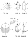
- Drawings 1A, 1B and 1C diagrammatically show the step of applying the support element 1 ( fig. 1A ) and container C with the support element 1 applied.
- the containers C with convex bottom preferably are bottles, e.g. PET bottles.
- the term "convex bottom” means a convexity facing outwards, that is downwards.
- the convex bottom is a hemispheric bottom.
- An example of such bottles is the one described in International Application no. PCT/IB2017/052798 to the same Applicant.
- the machine for applying strips made of flexible material usable for the objects of the present invention may be a labeler suitable for handling containers with a convex bottom which therefore do not remain in upright position when set down.
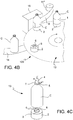
- FIG. 4C A peculiarity of a machine for applying strips made of flexible material of this type is shown in figure 4C , in which numeral 2 indicates a support plate comprising a lower retaining element 3 and an upper retaining element 4.
- Container C is released onto plate 2 by a distribution star (not shown) and the upper retaining element 4 is lowered onto the cap T of container C so as to keep container C pressed against the lower retaining element 3.
- Gripper 5 shown in the drawing is a further or alternative means of retaining the upper retaining element 4 by acting at the neck of container C.
- the lower retaining element 3 may have centering protrusions 6 arranged for example, in a triangle, or a concave surface (not shown) so as to house the end portion of the convex bottom of container C.
- the support material may be a plastic material, such as PET (polyethylene terephthalate), PP (polypropylene), OPP (oriented polypropylene), PVC (polyvinylchloride), etc., a paper material, a metal material, such as aluminum, aluminum alloys, iron alloys, or a polylaminate material, that is a multilayer material formed by layers of materials chosen from plastic, paper and metal.
- a plastic material such as PET (polyethylene terephthalate), PP (polypropylene), OPP (oriented polypropylene), PVC (polyvinylchloride), etc.
- PET polyethylene terephthalate
- PP polypropylene
- OPP oriented polypropylene
- PVC polyvinylchloride
- a paper material such as PET (polyethylene terephthalate), PP (polypropylene), OPP (oriented polypropylene), PVC (polyvinylchloride), etc.
- a paper material
- the support element 1 is in the form of a strip of said support material.
- strip made of support material means a portion of film of support material i) of such a rigidity as to support container C filled with the packing product in an upright position, ii) of such a flexibility as to be wrapped about the side surface S of the container, in particular by means of a machine for applying strips made of flexible material to said containers C, iii) of such a length "L” as to at least partially wrap the circumference of the side surface S of container C, and iv) of such a width "l” as to adhere to a portion of side surface S of container C and finish at the level of, or below the bottom F of container C.
- the rigidity and the flexibility of the strip of support element depend on the support material used and the thickness thereof, which varies according to the support material.
- thicknesses are used in the present case if compared with the thicknesses of a normal label (about 18 to 20 microns for plastic material, up to 100 microns for paper material).
- the support element may comprise reinforcing elements 7, 7' such as corrugations 7 (support element 101 in figure 2A ) or ripples 7' (support element 201 in figures 2B to 2D ).
- reinforcing elements 7, 7' such as corrugations 7 (support element 101 in figure 2A ) or ripples 7' (support element 201 in figures 2B to 2D ).
- the support element 1 also acts as label for container C, as shown in figure 3B .
- the face of the support element 1 comprises images or writings 8.
- the method of the invention may be carried out using various technologies and various labeling systems and machines, as described below.
- Figure 3A shows by way of example, a reel 10 on which there is wrapped a strip 9 of support material on which images or writings 8 were imprinted at regular intervals so as to later obtain the single support elements 1, 101, 201 by cutting.
- a first machine for carrying out the method of the invention is shown in figures 4A and 4B and comprises:
- each labeling unit 13 comprises a plate 2 comprising a lower retaining element 3. Plate 2 is rotating so as to promote the wrapping of the support element 1, 101, 201 on the side surface S of container C.
- the labeling unit 13 further comprises an upper retaining element 4 and/or 5 which acts on cap T and/or on the neck of container C so as to keep the latter pressed against the lower retaining element 3.
- the lower retaining element 3 may have centering protrusions 6 arranged for example, in a triangle, or a concave surface (not shown) so as to house the end portion of the convex bottom of container C.
- the containers C are fed to carousel 12 by means of a first transport system 14 and they are picked from the carousel by a second transport system 14' after the application of the support element 1, 101, 201.
- the transport systems 14, 14' in certain embodiments are made by means of conveyor belts, while they comprise a distribution star in other embodiments.
- a device 15 for applying a support element 1, 101, 201 on a container C is positioned downstream of the first transport system 14, with respect to the rotation direction of carousel 12.
- the application device 15, which is of conventional type, receives strip 9 (from which the support elements 1, 101, 201 are singularized) from a reel 10 by means of a series of idler rollers 11, 11', 11''.
- the application device 15 generally consists of a rotating drum on which surface is applied a vacuum in order to withhold strip 9 or the single support elements 1, 101, 201, and is arranged tangent with carousel 12.
- a device for applying an adhesive layer to the surface of strip 9 and/or a device for cutting the single support elements 1, 101, 201 from strip 9 may be positioned upstream of the application point of the support element on container C, with respect to the rotation direction of the drum.
- strip 9 is pre-glued, hence the device for applying the adhesive may be omitted.
- the cutting device acts when the head flap of strip 9 is already applied on the side surface S of container C.
- Figure 5 shows a different embodiment of machine 100, in which the support elements 1 are already singularized and die-cut and are contained in a dispenser 16 which feeds the application device 15, and therefore it does not comprise a device for cutting the support elements from a strip.
- Dispenser 16 may comprise a pusher 16' to keep the pack of support elements 1 pressed against the dispensing opening and therefore promote the outlet thereof.
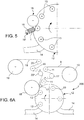
- Figures 6A and 6B show a different machine 200 for carrying out the method of the invention, comprising:
- Carousel 12 with the labeling units 13 and the transport systems 14, 14' are as described above.
- Strip 9 from which the single support elements 1, 101, 201 are obtained is unwound from a reel 10 and is brought, through a series of idler rollers 11, 11', 11", at a cutting device 17 which singularizes the support elements 1, 101, 201.
- the cutting device 17 is arranged at the application device 15, as described above.
- a film 18 is unwound from a second reel 19 and conducted, through a series of idler rollers 20, 20', 20", to the application device 15, as described above.
- Film 18 is adhesive or made adhesive by means of the application of a layer of glue by means of a specific device positioned upstream of the corresponding point of the application device 15 with the cutting device 17, with respect to the feeding direction of film 18.
- the support element 1, 101, 201 is adhered to film 18 which is applied to a container C immediately downstream with respect to the feeding direction of film 18. An adequate portion of film 18 may be cut from strip 18 either upstream of the device 17 for cutting strip 9 or immediately downstream thereof.
- Figure 7 shows a different embodiment of machine 200, in which the support elements 1 are already singularized and die-cut and are contained in a dispenser 16 arranged upstream of the application device 15, with respect to the feeding direction of film 18.
- Dispenser 16 may comprise a pusher 16' to keep the pack of support elements 1 pressed against the dispensing opening and therefore promote the grasping thereof by film 18.
- strip 9 and accordingly, the support elements 1, may act as labels and therefore have images or writings 8.
- Strip 9 or the single support elements 1, according to the technology used in the method of the invention, may be pre-printed with the images or writings 8.
- machine 100, 200 may comprise an in-line printing device 21 arranged between reel 10 and the device 15 for applying the support element 1 to a container C.
- the in-line printing device 21 may be a common ink jet or laser printer, chosen among the ones normally used for in-line printing of strips of plastic or paper material.
- an in-line printer may be positioned for example, at the application device 15, between the release point of the support elements 1, 101, 201 by dispenser 16 and the application point of the support elements on the containers C.
- the support element 101, 201 comprises stiffening corrugations 7 or ripples 7'.
- Figures 9 and 10 show two different devices for making such corrugations 7 or ripples 7' on the support elements 101, 201.
- Figure 9 diagrammatically shows a press device 22 comprising a mold 22a and a punch 22b, into which single support elements 1 for making a support element 201 with ripples 7' are fed.
- the press device 22 may be heated so as to carry out a thermal pressing, in particular usable for forming support elements 101, 201 made of plastic material.
- Such a device which is diagrammatically shown in a simplified manner in the drawing, may be arranged both in line, upstream of dispenser 16, and separately so as to preform the support elements 201.
- the elements 101 similarly may be formed.
- Figure 10 instead shows, again in diagrammatic and simplified manner, an in-line forming device 23 which, if the support material is a plastic material, comprises a heating device 24 and a pressing device 25 arranged downstream of the heating device 24, with respect to the feeding direction of strip 9.
- a heating device 24 which in particularly is usable to form a strip 9 made of plastic, paper, metal or polylaminate material, provides for example preheating strip 9 up to a softening point thereof in the case of plastic material, and then causing it to pass through the pressing device 25, which for example, may comprise a pair of opposed rollers, on the surface of which corrugation 7 or ripple 7' to be made is reproduced in positive and negative manner, respectively.
- the pressing device 25 which for example, may comprise a pair of opposed rollers, on the surface of which corrugation 7 or ripple 7' to be made is reproduced in positive and negative manner, respectively.
- the pressing device 23, which is described arranged in line in the machine of the invention, may also be used as separate device so as to preform strip 101, 201, which is then used in the method of the invention.
- the method of the invention therefore achieves the preset objects because it allows a container with convex bottom in conjunction with a support base to be obtained in a single passage and with same equipment, in a simple manner and with reduced cost by also using labeling machines of commercial type.
- the support element may also act as label, whereby the labeling step and coupling step with a support base occurs simultaneously with a same passage.
Landscapes
- Engineering & Computer Science (AREA)
- Mechanical Engineering (AREA)
- Ceramic Engineering (AREA)
- Labeling Devices (AREA)
- Details Of Rigid Or Semi-Rigid Containers (AREA)
Applications Claiming Priority (1)
| Application Number | Priority Date | Filing Date | Title |
|---|---|---|---|
| IT102018000003549A IT201800003549A1 (it) | 2018-03-14 | 2018-03-14 | Procedimento per la realizzazione di un contenitore con supporto autoreggente |
Publications (2)
| Publication Number | Publication Date |
|---|---|
| EP3539889A2 true EP3539889A2 (fr) | 2019-09-18 |
| EP3539889A3 EP3539889A3 (fr) | 2019-11-27 |
Family
ID=62530374
Family Applications (1)
| Application Number | Title | Priority Date | Filing Date |
|---|---|---|---|
| EP19160878.5A Withdrawn EP3539889A3 (fr) | 2018-03-14 | 2019-03-05 | Procédé de fabrication d'un récipient à support auto-porteur |
Country Status (5)
| Country | Link |
|---|---|
| US (1) | US20190283918A1 (fr) |
| EP (1) | EP3539889A3 (fr) |
| CN (1) | CN110271728A (fr) |
| IT (1) | IT201800003549A1 (fr) |
| MX (1) | MX2019002909A (fr) |
Families Citing this family (1)
| Publication number | Priority date | Publication date | Assignee | Title |
|---|---|---|---|---|
| JP6657715B2 (ja) * | 2015-09-29 | 2020-03-04 | 横浜ゴム株式会社 | パンク修理液収容容器 |
Family Cites Families (5)
| Publication number | Priority date | Publication date | Assignee | Title |
|---|---|---|---|---|
| FR1559742A (fr) * | 1967-12-29 | 1969-03-14 | ||
| JPH06345096A (ja) * | 1993-06-04 | 1994-12-20 | Mitsubishi Plastics Ind Ltd | 脚台付きポリエステルボトル |
| JP2002002645A (ja) * | 2000-06-26 | 2002-01-09 | Kikkoman Corp | ラベル貼り合わせ部ズレ調整機構付ラベル貼着装置 |
| EP1587736B1 (fr) * | 2003-01-29 | 2006-10-18 | Benco Pack S.p.A. | Procede et installations permettant d'appliquer une etiquette thermoretractable sur des contenants |
| DE202013103957U1 (de) * | 2013-09-03 | 2014-12-04 | Krones Ag | Etikettiermaschine mit Servomotorantrieb |
-
2018
- 2018-03-14 IT IT102018000003549A patent/IT201800003549A1/it unknown
-
2019
- 2019-03-05 EP EP19160878.5A patent/EP3539889A3/fr not_active Withdrawn
- 2019-03-13 MX MX2019002909A patent/MX2019002909A/es unknown
- 2019-03-13 US US16/352,487 patent/US20190283918A1/en not_active Abandoned
- 2019-03-14 CN CN201910192187.2A patent/CN110271728A/zh active Pending
Also Published As
| Publication number | Publication date |
|---|---|
| IT201800003549A1 (it) | 2019-09-14 |
| EP3539889A3 (fr) | 2019-11-27 |
| US20190283918A1 (en) | 2019-09-19 |
| CN110271728A (zh) | 2019-09-24 |
| MX2019002909A (es) | 2019-09-16 |
Similar Documents
| Publication | Publication Date | Title |
|---|---|---|
| AU715798B2 (en) | Applying a tactilely distinguishable marking on an article | |
| US8087147B2 (en) | Method of reinforcing a plastic foam cup | |
| US7694843B2 (en) | Reinforced plastic foam cup, method of and apparatus for manufacturing same | |
| US7918005B2 (en) | Reinforced foam cup, method of and apparatus for manufacturing same | |
| US7527843B2 (en) | Support provided with two series of labels | |
| US20060281619A1 (en) | Reinforced plastic foam cup, method of and apparatus for manufacturing same | |
| US5344305A (en) | Apparatus for in-mold labelling | |
| US9511885B2 (en) | Cluster pack and method for forming cluster packs | |
| JP3504249B2 (ja) | 多連式容器 | |
| US20240242637A1 (en) | Two-ply channel liner, label, and roll | |
| US20080017321A1 (en) | Method and device for high speed labeling of articles using two-sided labelstock | |
| EP3539889A2 (fr) | Procédé de fabrication d'un récipient à support auto-porteur | |
| CN109166451A (zh) | 一种高透明的用于pet注塑的模内标签制作方法 | |
| CN111867942A (zh) | 有衬里的容器 | |
| EP0974524A1 (fr) | Emballage muni d'une étiquette et procédé d'étiquetage | |
| US7077928B2 (en) | Process for the manufacture of a label stock carrier | |
| US7294219B2 (en) | Label-seal manufacturing method and the resulting improved label-seal | |
| WO2018085471A2 (fr) | Système d'emballage | |
| EP2364252B1 (fr) | Procede et dispositif pour emballer un produit dans un emballage a barquette et enveloppe | |
| CN100540403C (zh) | 热贴膜封口设备 | |
| US20230074174A1 (en) | Round trip container | |
| US20240317452A1 (en) | Round Trip Container | |
| KR100885043B1 (ko) | 전자부품 포장방법 및 포장구조체 | |
| CA3234771A1 (fr) | Procede, dispositif d'application et dispositif d?emballage pour produire des unites d'emballage | |
| JP2898888B2 (ja) | 注ぎ口付き容器の製造方法 |
Legal Events
| Date | Code | Title | Description |
|---|---|---|---|
| PUAI | Public reference made under article 153(3) epc to a published international application that has entered the european phase |
Free format text: ORIGINAL CODE: 0009012 |
|
| STAA | Information on the status of an ep patent application or granted ep patent |
Free format text: STATUS: THE APPLICATION HAS BEEN PUBLISHED |
|
| AK | Designated contracting states |
Kind code of ref document: A2 Designated state(s): AL AT BE BG CH CY CZ DE DK EE ES FI FR GB GR HR HU IE IS IT LI LT LU LV MC MK MT NL NO PL PT RO RS SE SI SK SM TR |
|
| AX | Request for extension of the european patent |
Extension state: BA ME |
|
| PUAL | Search report despatched |
Free format text: ORIGINAL CODE: 0009013 |
|
| AK | Designated contracting states |
Kind code of ref document: A3 Designated state(s): AL AT BE BG CH CY CZ DE DK EE ES FI FR GB GR HR HU IE IS IT LI LT LU LV MC MK MT NL NO PL PT RO RS SE SI SK SM TR |
|
| AX | Request for extension of the european patent |
Extension state: BA ME |
|
| RIC1 | Information provided on ipc code assigned before grant |
Ipc: B65D 25/24 20060101ALI20191024BHEP Ipc: B65C 9/00 20060101ALI20191024BHEP Ipc: B65D 23/00 20060101AFI20191024BHEP |
|
| RBV | Designated contracting states (corrected) |
Designated state(s): AL AT BE BG CH CY CZ DE DK EE ES FI FR GB GR HR HU IE IS IT LI LT LU LV MC MK MT NL NO PL PT RO RS SE SI SK SM TR |
|
| STAA | Information on the status of an ep patent application or granted ep patent |
Free format text: STATUS: REQUEST FOR EXAMINATION WAS MADE |
|
| 17P | Request for examination filed |
Effective date: 20200414 |
|
| STAA | Information on the status of an ep patent application or granted ep patent |
Free format text: STATUS: EXAMINATION IS IN PROGRESS |
|
| STAA | Information on the status of an ep patent application or granted ep patent |
Free format text: STATUS: EXAMINATION IS IN PROGRESS |
|
| 17Q | First examination report despatched |
Effective date: 20201209 |
|
| STAA | Information on the status of an ep patent application or granted ep patent |
Free format text: STATUS: THE APPLICATION IS DEEMED TO BE WITHDRAWN |
|
| 18D | Application deemed to be withdrawn |
Effective date: 20211106 |