EP3537714B1 - Dispositif, système et procédé de génération d'image vidéo de vue à vol d'oiseau et programme associé - Google Patents
Dispositif, système et procédé de génération d'image vidéo de vue à vol d'oiseau et programme associé Download PDFInfo
- Publication number
- EP3537714B1 EP3537714B1 EP17898960.4A EP17898960A EP3537714B1 EP 3537714 B1 EP3537714 B1 EP 3537714B1 EP 17898960 A EP17898960 A EP 17898960A EP 3537714 B1 EP3537714 B1 EP 3537714B1
- Authority
- EP
- European Patent Office
- Prior art keywords
- bird
- eye view
- vehicle
- view image
- virtual viewpoint
- Prior art date
- Legal status (The legal status is an assumption and is not a legal conclusion. Google has not performed a legal analysis and makes no representation as to the accuracy of the status listed.)
- Active
Links
- 238000000034 method Methods 0.000 title claims description 60
- 240000004050 Pentaglottis sempervirens Species 0.000 claims description 371
- 235000004522 Pentaglottis sempervirens Nutrition 0.000 claims description 371
- 238000006243 chemical reaction Methods 0.000 claims description 105
- 238000001514 detection method Methods 0.000 claims description 17
- 238000004590 computer program Methods 0.000 claims description 8
- 238000010586 diagram Methods 0.000 description 42
- 230000000694 effects Effects 0.000 description 1
- 238000005401 electroluminescence Methods 0.000 description 1
- 239000004973 liquid crystal related substance Substances 0.000 description 1
- 230000003287 optical effect Effects 0.000 description 1
- 238000003672 processing method Methods 0.000 description 1
- 239000004065 semiconductor Substances 0.000 description 1
Images


Classifications
-
- H—ELECTRICITY
- H04—ELECTRIC COMMUNICATION TECHNIQUE
- H04N—PICTORIAL COMMUNICATION, e.g. TELEVISION
- H04N7/00—Television systems
- H04N7/18—Closed-circuit television [CCTV] systems, i.e. systems in which the video signal is not broadcast
- H04N7/181—Closed-circuit television [CCTV] systems, i.e. systems in which the video signal is not broadcast for receiving images from a plurality of remote sources
-
- H—ELECTRICITY
- H04—ELECTRIC COMMUNICATION TECHNIQUE
- H04N—PICTORIAL COMMUNICATION, e.g. TELEVISION
- H04N5/00—Details of television systems
- H04N5/222—Studio circuitry; Studio devices; Studio equipment
- H04N5/262—Studio circuits, e.g. for mixing, switching-over, change of character of image, other special effects ; Cameras specially adapted for the electronic generation of special effects
- H04N5/2628—Alteration of picture size, shape, position or orientation, e.g. zooming, rotation, rolling, perspective, translation
-
- B—PERFORMING OPERATIONS; TRANSPORTING
- B60—VEHICLES IN GENERAL
- B60R—VEHICLES, VEHICLE FITTINGS, OR VEHICLE PARTS, NOT OTHERWISE PROVIDED FOR
- B60R1/00—Optical viewing arrangements; Real-time viewing arrangements for drivers or passengers using optical image capturing systems, e.g. cameras or video systems specially adapted for use in or on vehicles
- B60R1/20—Real-time viewing arrangements for drivers or passengers using optical image capturing systems, e.g. cameras or video systems specially adapted for use in or on vehicles
- B60R1/22—Real-time viewing arrangements for drivers or passengers using optical image capturing systems, e.g. cameras or video systems specially adapted for use in or on vehicles for viewing an area outside the vehicle, e.g. the exterior of the vehicle
- B60R1/23—Real-time viewing arrangements for drivers or passengers using optical image capturing systems, e.g. cameras or video systems specially adapted for use in or on vehicles for viewing an area outside the vehicle, e.g. the exterior of the vehicle with a predetermined field of view
- B60R1/27—Real-time viewing arrangements for drivers or passengers using optical image capturing systems, e.g. cameras or video systems specially adapted for use in or on vehicles for viewing an area outside the vehicle, e.g. the exterior of the vehicle with a predetermined field of view providing all-round vision, e.g. using omnidirectional cameras
-
- B—PERFORMING OPERATIONS; TRANSPORTING
- B60—VEHICLES IN GENERAL
- B60R—VEHICLES, VEHICLE FITTINGS, OR VEHICLE PARTS, NOT OTHERWISE PROVIDED FOR
- B60R11/00—Arrangements for holding or mounting articles, not otherwise provided for
- B60R11/02—Arrangements for holding or mounting articles, not otherwise provided for for radio sets, television sets, telephones, or the like; Arrangement of controls thereof
-
- G—PHYSICS
- G06—COMPUTING; CALCULATING OR COUNTING
- G06T—IMAGE DATA PROCESSING OR GENERATION, IN GENERAL
- G06T11/00—2D [Two Dimensional] image generation
-
- G—PHYSICS
- G06—COMPUTING; CALCULATING OR COUNTING
- G06V—IMAGE OR VIDEO RECOGNITION OR UNDERSTANDING
- G06V20/00—Scenes; Scene-specific elements
- G06V20/50—Context or environment of the image
- G06V20/56—Context or environment of the image exterior to a vehicle by using sensors mounted on the vehicle
- G06V20/58—Recognition of moving objects or obstacles, e.g. vehicles or pedestrians; Recognition of traffic objects, e.g. traffic signs, traffic lights or roads
-
- H—ELECTRICITY
- H04—ELECTRIC COMMUNICATION TECHNIQUE
- H04N—PICTORIAL COMMUNICATION, e.g. TELEVISION
- H04N23/00—Cameras or camera modules comprising electronic image sensors; Control thereof
- H04N23/60—Control of cameras or camera modules
- H04N23/698—Control of cameras or camera modules for achieving an enlarged field of view, e.g. panoramic image capture
-
- H—ELECTRICITY
- H04—ELECTRIC COMMUNICATION TECHNIQUE
- H04N—PICTORIAL COMMUNICATION, e.g. TELEVISION
- H04N7/00—Television systems
- H04N7/18—Closed-circuit television [CCTV] systems, i.e. systems in which the video signal is not broadcast
-
- B—PERFORMING OPERATIONS; TRANSPORTING
- B60—VEHICLES IN GENERAL
- B60R—VEHICLES, VEHICLE FITTINGS, OR VEHICLE PARTS, NOT OTHERWISE PROVIDED FOR
- B60R2300/00—Details of viewing arrangements using cameras and displays, specially adapted for use in a vehicle
- B60R2300/10—Details of viewing arrangements using cameras and displays, specially adapted for use in a vehicle characterised by the type of camera system used
- B60R2300/105—Details of viewing arrangements using cameras and displays, specially adapted for use in a vehicle characterised by the type of camera system used using multiple cameras
-
- B—PERFORMING OPERATIONS; TRANSPORTING
- B60—VEHICLES IN GENERAL
- B60R—VEHICLES, VEHICLE FITTINGS, OR VEHICLE PARTS, NOT OTHERWISE PROVIDED FOR
- B60R2300/00—Details of viewing arrangements using cameras and displays, specially adapted for use in a vehicle
- B60R2300/30—Details of viewing arrangements using cameras and displays, specially adapted for use in a vehicle characterised by the type of image processing
-
- B—PERFORMING OPERATIONS; TRANSPORTING
- B60—VEHICLES IN GENERAL
- B60R—VEHICLES, VEHICLE FITTINGS, OR VEHICLE PARTS, NOT OTHERWISE PROVIDED FOR
- B60R2300/00—Details of viewing arrangements using cameras and displays, specially adapted for use in a vehicle
- B60R2300/60—Details of viewing arrangements using cameras and displays, specially adapted for use in a vehicle characterised by monitoring and displaying vehicle exterior scenes from a transformed perspective
- B60R2300/602—Details of viewing arrangements using cameras and displays, specially adapted for use in a vehicle characterised by monitoring and displaying vehicle exterior scenes from a transformed perspective with an adjustable viewpoint
- B60R2300/605—Details of viewing arrangements using cameras and displays, specially adapted for use in a vehicle characterised by monitoring and displaying vehicle exterior scenes from a transformed perspective with an adjustable viewpoint the adjustment being automatic
-
- B—PERFORMING OPERATIONS; TRANSPORTING
- B60—VEHICLES IN GENERAL
- B60R—VEHICLES, VEHICLE FITTINGS, OR VEHICLE PARTS, NOT OTHERWISE PROVIDED FOR
- B60R2300/00—Details of viewing arrangements using cameras and displays, specially adapted for use in a vehicle
- B60R2300/60—Details of viewing arrangements using cameras and displays, specially adapted for use in a vehicle characterised by monitoring and displaying vehicle exterior scenes from a transformed perspective
- B60R2300/607—Details of viewing arrangements using cameras and displays, specially adapted for use in a vehicle characterised by monitoring and displaying vehicle exterior scenes from a transformed perspective from a bird's eye viewpoint
-
- G—PHYSICS
- G06—COMPUTING; CALCULATING OR COUNTING
- G06T—IMAGE DATA PROCESSING OR GENERATION, IN GENERAL
- G06T2207/00—Indexing scheme for image analysis or image enhancement
- G06T2207/30—Subject of image; Context of image processing
- G06T2207/30248—Vehicle exterior or interior
- G06T2207/30252—Vehicle exterior; Vicinity of vehicle
Definitions
- the present invention relates to a bird's-eye view image generating device, a bird's-eye view image generating system, a bird's-eye view image generating method, and a computer program.
- US 2007/120656 A discloses a vehicle surrounding display device.
- US 2010/134325 A discloses an image processing apparatus, image processing method, and recording medium.
- the obstacle is displayed to be relatively smaller.
- the obstacle may be difficult to correctly recognize the obstacle.
- the obstacle may be difficult to correctly grasp a positional relation between the obstacle and the vehicle. In this way, there is room for improvement in displaying a detected obstacle as a bird's-eye view image.
- the present invention is made in view of such a situation, and an object of the present invention is to display an image so that the positional relation between the detected obstacle and the vehicle can be intuitively grasped.
- a bird's-eye view image generating device a bird's-eye view image generating system, a bird's-eye view image generating method, and a computer program as set forth in the appended claims is provided.
- a bird's-eye view image generating device according to claim 1 is disclosed.
- a bird's-eye view image generating system includes the above bird's-eye view image generating device, and at least one of a plurality of cameras that photograph the periphery of the vehicle, the display unit, and a detection unit that detects an obstacle and outputs obstacle information.
- a bird's-eye view image generating method is disclosed.
- a computer program according to claim 6 is disclosed.
- an image can be displayed so that a positional relation between a detected obstacle and a vehicle can be intuitively grasped.
- a front and rear direction is assumed to be a direction parallel with a traveling direction at the time when a vehicle moves straight forward, a direction from a driver's seat toward a windshield is assumed to be "front” of the front and rear direction, and a direction from the windshield toward the driver's seat is assumed to be “rear” of the front and rear direction.
- the front and rear direction is assumed to be an X-axis direction.
- a left and right direction is a direction that is horizontally orthogonal to the front and rear direction.
- a left side is "left", and a right side is “right” with respect to the windshield.
- the left and right direction is assumed to be a Y-axis direction.
- An up and down direction is a direction orthogonal to the front and rear direction and the left and right direction.
- the up and down direction is assumed to be a Z-axis direction.
- the front and rear direction, the left and right direction, and a vertical direction are three-dimensionally orthogonal to each other.
- "front and rear”, “left and right”, and “up and down” are represented in a state in which the bird's-eye view image generating system 1 is mounted on the vehicle.
- FIG. 1 is a block diagram illustrating a configuration example of a bird's-eye view image generating system according to a first embodiment.
- the bird's-eye view image generating system 1 is mounted on a vehicle V.
- a portable device that can be used for the vehicle V may be used.
- the bird's-eye view image generating system 1 includes a front camera 11, a rear camera 12, a left side camera 13, a right side camera 14, a sensor group (obstacle sensor) 20, a display panel (display unit) 30, and the bird's-eye view image generating device 40.
- FIG. 2 is a schematic diagram for explaining an example of a position of a virtual viewpoint in the bird's-eye view image generating system according to the first embodiment.
- the front camera 11 is disposed at the front of the vehicle V, and photographs the periphery around the front of the vehicle V.
- the front camera 11 photographs, for example, a photographing range A1 of about 180°.
- the front camera 11 outputs a photographed image to an image data acquisition unit 42 of the bird's-eye view image generating device 40.
- the rear camera 12 is disposed at the rear of the vehicle V, and photographs the periphery around the rear of the vehicle V.
- the rear camera 12 photographs, for example, a photographing range A2 of about 180°.
- the rear camera 12 outputs a photographed image to the image data acquisition unit 42 of the bird's-eye view image generating device 40.
- the left side camera 13 is disposed on the left side of the vehicle V, and photographs the periphery around the left side of the vehicle V.
- the left side camera 13 photographs, for example, a photographing range A3 of about 180°.
- the left side camera 13 outputs a photographed image to the image data acquisition unit 42 of the bird's-eye view image generating device 40.
- the right side camera 14 is disposed on the right side of the vehicle V, and photographs the periphery around the right side of the vehicle V.
- the right side camera 14 photographs, for example, a photographing range A4 (not illustrated) of about 180°.
- the right side camera 14 outputs a photographed image to the image data acquisition unit 42 of the bird's-eye view image generating device 40.
- the periphery of the vehicle V is photographed in all directions.
- the sensor group 20 is a detection unit that detects an obstacle Q around the vehicle V.
- the sensor group 20 can detect the obstacle Q in a range including a display range A of a bird's-eye view image.
- the sensor group 20 includes a front sensor, a rear sensor, a left side sensor, and a right side sensor.
- the sensor group 20 can perform sensing in a distance from several tens of meters to several hundreds of meters depending on a sensing system. In a case of being used for this object, the sensor group 20 detects the obstacle Q in a distance of about 5 m from the vehicle V.
- Various systems can be applied to the sensor group 20 such as an infrared sensor, an ultrasonic sensor, a millimeter wave sensor, a sensor based on image recognition, and a combination of a plurality of systems of sensors.
- the front sensor is disposed at the front of the vehicle V, and detects the obstacle Q present in a range around the front of the vehicle V.
- the front sensor detects an object having a height from the ground that may be brought into contact with the vehicle V when the vehicle V moves forward.
- the front sensor detects, for example, the obstacle Q at a distance of about 5 m from the vehicle V.
- a detection range of the front sensor overlaps with the photographing range A1 of the front camera 11.
- the detection range of the front sensor may overlap with part of detection ranges of the left side sensor and the right side sensor.
- the front sensor is constituted of a combination of a plurality of sensors. Due to this, the front sensor detects subdivided directions of the obstacle Q.
- the front sensor outputs obstacle information of the detected obstacle Q to an obstacle information acquisition unit 43 of the bird's-eye view image generating device 40.
- the rear sensor is disposed at the rear of the vehicle V, and detects the obstacle Q present in a range around the rear of the vehicle V.
- the rear sensor detects an object having a height from the ground that may be brought into contact with the vehicle V when the vehicle V moves backward.
- the rear sensor detects, for example, the obstacle Q at a distance of about 5 m from the vehicle V.
- a detection range of the rear sensor overlaps with the photographing range A2 of the rear camera 12.
- the detection range of the rear sensor may overlap with part of the detection ranges of the left side sensor and the right side sensor.
- the rear sensor is constituted of a combination of a plurality of sensors. Due to this, the rear sensor detects subdivided directions of the obstacle Q.
- the rear sensor outputs obstacle information of the detected obstacle Q to the obstacle information acquisition unit 43 of the bird's-eye view image generating device 40.
- the left side sensor is disposed on the left side of the vehicle V, and detects the obstacle Q present in a range around the left side of the vehicle V.
- the left side sensor detects an object having a height from the ground that may be brought into contact with the vehicle V when the vehicle V moves forward or backward while being steered.
- the left side sensor detects, for example, the obstacle Q at a distance of about 5 m from the vehicle V.
- a detection range of the left side sensor overlaps with the photographing range A3 of the left side camera 13.
- the detection range of the left side sensor may overlap with part of the detection ranges of the front sensor and the rear sensor.
- the left side sensor is constituted of a combination of a plurality of sensors. Due to this, the left side sensor detects subdivided directions of the obstacle Q.
- the left side sensor outputs obstacle information of the detected obstacle Q to the obstacle information acquisition unit 43 of the bird's-eye view image generating device 40.
- the right side sensor is disposed on the right side of the vehicle V, and detects the obstacle Q present in a range around the right side of the vehicle V.
- the right side sensor detects an object having a height from the ground that may be brought into contact with the vehicle V when the vehicle V moves forward or backward while being steered.
- the right side sensor detects, for example, the obstacle Q at a distance of about 5 m from the vehicle V.
- a detection range of the right side sensor overlaps with the photographing range A4 of the right side camera 14.
- the detection range of the right side sensor may overlap with part of the detection ranges of the front sensor and the rear sensor.
- the right side sensor is constituted of a combination of a plurality of sensors. Due to this, the right side sensor detects subdivided directions of the obstacle Q.
- the right side sensor outputs obstacle information of the detected obstacle Q to the obstacle information acquisition unit 43 of the bird's-eye view image generating device 40.
- the display panel 30 is, for example, a display including a liquid crystal display (LCD) or an organic electro-luminescence (organic EL) display.
- the display panel 30 displays a bird's-eye view image 100 (refer to FIG. 3 ) based on an image signal output from the bird's-eye view image generating device 40 of the bird's-eye view image generating system 1.
- the display panel 30 may be dedicated to the bird's-eye view image generating system 1, or may be used by another system including a navigation system at the same time, for example.
- the display panel 30 is disposed at a position that is easily visually recognized by a driver.
- the display panel 30 may be divided into a plurality of display ranges.
- the display panel 30 includes a display range for displaying the bird's-eye view image 100 and a display range for displaying a navigation screen or an audio screen disposed on a side of the display range of the bird's-eye view image 100.
- the display range for displaying the bird's-eye view image 100 has a vertically long rectangular shape.
- the bird's-eye view image generating device 40 includes a control unit 41 and a storage unit 49.
- the control unit 41 is, for example, an arithmetic processing device constituted of a central processing unit (CPU) and the like.
- the control unit 41 loads a computer program stored in the storage unit 49 into a memory, and executes a command included in the computer program.
- the control unit 41 includes the image data acquisition unit 42, the obstacle information acquisition unit 43, a vehicle information acquisition unit 44, a bird's-eye view image generation unit 45, and a display control unit 48.
- the image data acquisition unit 42 acquires periphery image data obtained by photographing the periphery of the vehicle V. More specifically, the image data acquisition unit 42 acquires the periphery image data output from the front camera 11, the rear camera 12, the left side camera 13, and the right side camera 14. The image data acquisition unit 42 outputs the acquired periphery image data to the bird's-eye view image generation unit 45.
- the obstacle information acquisition unit 43 acquires the obstacle information of the obstacle Q detected in the periphery of the vehicle V, and specifies a position of the detected obstacle Q on the bird's-eye view image. More specifically, the obstacle information acquisition unit 43 acquires the obstacle information output from the sensor group 20. The obstacle information acquisition unit 43 acquires subdivided directions of the obstacle Q based on an attachment position of a sensor that has output the obstacle information and the detection range of the sensor for the obstacle Q. The obstacle information acquisition unit 43 acquires the obstacle information including a distance to the detected obstacle Q. The obstacle information acquisition unit 43 specifies the position of the obstacle Q on the bird's-eye view image based on the acquired directions and distance of the obstacle Q.
- the vehicle information acquisition unit 44 acquires vehicle information to be a trigger for displaying the bird's-eye view image 100 such as a gear operation information of the vehicle V from a controller area network (CAN), various sensors for sensing a state of the vehicle V, and the like.
- vehicle information includes information indicating a traveling direction of the vehicle V.
- the vehicle information acquisition unit 44 outputs the acquired vehicle information to the bird's-eye view image generation unit 45.
- the bird's-eye view image generation unit 45 By performing viewpoint conversion processing on pieces of the periphery image data acquired by the image data acquisition unit 42 to be combined, the bird's-eye view image generation unit 45 generates the bird's-eye view image 100 having a virtual viewpoint P on an upper side of the vehicle V.
- the virtual viewpoint P is positioned above the center of the vehicle V.
- the virtual viewpoint P is a viewpoint of looking down the vehicle V from right above the center thereof.
- the "center of the vehicle V” is the center in a vehicle width direction of the vehicle V and the center in the front and rear direction thereof.
- "Right above the vehicle V” is a position on a perpendicular with respect to a reference surface of the vehicle V.
- the "reference surface” is, in a case in which the vehicle V is positioned on a horizontal and flat road surface, a plane horizontal to the road surface.
- a position of the virtual viewpoint P is assumed to be (x, y, z).
- FIG. 3 is a diagram illustrating an example of the bird's-eye view image generated by the bird's-eye view image generating system according to the first embodiment.
- the bird's-eye view image 100 is displayed by combining periphery images in the display range A on which viewpoint conversion processing is performed with the virtual viewpoint P.
- the bird's-eye view image 100 includes a front image 101, a rear image 102, a left side image 103, and a right side image 104.
- a display area of the front image 101 and a display area of the rear image 102 have the same size.
- a display area of the left side image 103 and a display area of the right side image 104 have the same size.
- a host vehicle icon 200 indicating the vehicle V is displayed.
- the host vehicle icon 200 indicates a form of looking down the vehicle V from right above.
- FIG. 3 illustrates, for explanation, oblique dashed lines indicating a combining boundary B1 between the front image 101 and the left side image 103, a combining boundary B2 between the front image 101 and the right side image 104, a combining boundary B3 between the rear image 102 and the left side image 103, and a combining boundary B4 between the rear image 102 and the right side image 104, but the dashed lines are not necessarily displayed in the bird's-eye view image 100 that is actually displayed on the display panel 30.
- the combining boundary B1, the combining boundary B2, the combining boundary B3, and the combining boundary B4 are not required to be specifically distinguished from each other, each of them is referred to as a combining boundary B.
- the bird's-eye view image generation unit 45 In a case in which there is an obstacle satisfying a predetermined condition, the bird's-eye view image generation unit 45 generates a bird's-eye view image obtained by performing viewpoint conversion processing on periphery images acquired by the image data acquisition unit 42 to be combined to cause a virtual viewpoint PA to be positioned being separated from the virtual viewpoint P positioned right above the vehicle V in at least one of the vehicle width direction and the front and rear direction so that the vehicle V and the obstacle Q can be overlooked, based on positional information of the obstacle Q acquired by the obstacle information acquisition unit 43.
- the predetermined condition is a condition for detecting the obstacle Q.
- the predetermined condition is that the obstacle Q is positioned in the traveling direction of the vehicle V.
- the obstacle Q is positioned in the traveling direction of the vehicle V.
- the obstacle Q is positioned in the rear of a front end of the vehicle V when the vehicle V moves backward.
- the control unit 41 determines that the predetermined condition is satisfied, and detects the obstacle Q.
- the present embodiment which is not part of the invention as claimed, describes a case in which the vehicle V moves backward.
- the bird's-eye view image generation unit 45 includes a viewpoint conversion processing unit 451, a cut-out processing unit 452, and a combination processing unit 453.
- the viewpoint conversion processing unit 451 performs viewpoint conversion processing on the periphery image data acquired by the image data acquisition unit 42 so as to look down the vehicle V from the above virtual viewpoint P. More specifically, the viewpoint conversion processing unit 451 generates an image subjected to viewpoint conversion processing based on the periphery image data photographed by the front camera 11, the rear camera 12, the left side camera 13, and the right side camera 14. As a method for viewpoint conversion processing, any known method can be used, and the method is not limited.
- the viewpoint conversion processing unit 451 outputs the periphery image data subjected to the viewpoint conversion processing to the cut-out processing unit 452.
- the viewpoint conversion processing unit 451 performs the viewpoint conversion processing to generate an image so as to cause the virtual viewpoint PA to be positioned being separated from the virtual viewpoint P positioned right above the vehicle V in at least one of the vehicle width direction and the front and rear direction so that the vehicle V and the obstacle Q can be overlooked, based on the positional information of the obstacle Q acquired by the obstacle information acquisition unit 43.
- the viewpoint conversion processing unit 451 when there is the obstacle Q positioned in the traveling direction of the vehicle V, the viewpoint conversion processing unit 451 generates an image subjected to the viewpoint conversion processing by causing the position of the virtual viewpoint to be the virtual viewpoint PA separated from the virtual viewpoint P so that a relative positional relation between the vehicle V and the obstacle Q can be recognized.
- the viewpoint conversion processing unit 451 outputs the periphery image data subjected to the viewpoint conversion processing to the cut-out processing unit 452.
- a relative positional relation between the vehicle V and the obstacle Q can be recognized means that the vehicle V and the obstacle Q are displayed without overlapping with each other in the bird's-eye view image. Additionally, “a relative positional relation between the vehicle V and the obstacle Q can be recognized” means that the relative positional relation between the vehicle V and the obstacle Q in the bird's-eye view image is changed depending on a change in a relative distance between the vehicle V and the obstacle Q when the vehicle V or the obstacle Q moves.
- the virtual viewpoint PA is preferably positioned so that an angle of view of the bird's-eye view image in a direction in which the obstacle is detected is substantially the same as an angle of view of the bird's-eye view image 100 from the virtual viewpoint P.
- the bird's-eye view image 100 from the virtual viewpoint P and the bird's-eye view image obtained by moving the virtual viewpoint to the virtual viewpoint PA use the same image, but a region of an appropriate virtual projection surface is used for the bird's-eye view image corresponding to the position of the virtual viewpoint.
- the position of the obstacle on the bird's-eye view image can be easily grasped when the position of the virtual viewpoint is changed.
- the virtual viewpoint PA is assumed to be in the rear of the vehicle V
- the rear image in the direction in which the virtual viewpoint PA is positioned has an angle of view substantially the same as a cut-out angle of view of the rear image 102 from the virtual viewpoint P
- the front image in a direction opposite to the virtual viewpoint PA across the vehicle V has a cut-out angle of view that is wider toward the front of the vehicle than that of the front image 101 from the virtual viewpoint P. Accordingly, the bird's-eye view image that seems to be looked down from the virtual viewpoint PA can be generated.
- FIG. 4 is a schematic diagram for explaining the position of the virtual viewpoint in the bird's-eye view image generating system according to the first embodiment.
- FIG. 5 is a schematic diagram for explaining the position of the virtual viewpoint in the bird's-eye view image generating system according to the first embodiment.
- the angle of view of the bird's-eye view image from the virtual viewpoint PA on the curved surface is the same as the angle of view of the bird's-eye view image 100 from the virtual viewpoint P, so that the size of the obstacle Q displayed in the bird's-eye view image is not changed.
- the bird's-eye view image in which the relative positional relation between the obstacle Q and the vehicle V can be intuitively grasped is generated.
- the virtual viewpoint PA is preferably disposed at a position separated from the center of the vehicle V by a distance larger than a distance between the center of the vehicle V and the obstacle Q. Accordingly, the bird's-eye view image in which the relative positional relation between the obstacle Q and the vehicle V can be easily recognized is generated.
- FIG. 6 is a schematic diagram for explaining an example of the position of the virtual viewpoint in the bird's-eye view image generating system according to the first embodiment.
- FIG. 7 is a schematic diagram for explaining an example of the position of the virtual viewpoint in the bird's-eye view image generating system according to the first embodiment.
- a position of the virtual viewpoint PA1 is represented as (xA1, yA1, zA1).
- the virtual viewpoint PA1 is positioned on the left rear side of the vehicle V.
- the virtual viewpoint PA1 is positioned on a left front side of the obstacle Q when viewed in the Z-axis direction.
- the virtual viewpoint PA1 is positioned on a left rear side of the virtual viewpoint P when viewed in the Z-axis direction.
- the virtual viewpoint PA1 is separated from the center of the vehicle V by a distance larger than the distance between the center of the vehicle V and the obstacle Q.
- the virtual viewpoint PA1 is a viewpoint of obliquely looking down the vehicle V from the left rear side.
- the cut-out processing unit 452 performs cut-out processing of cutting out an image of a predetermined range from the periphery image data subjected to the viewpoint conversion processing.
- the cut-out processing unit 452 cuts out a front cut-out range from the periphery image data from the front camera 11 that has been subjected to the viewpoint conversion processing.
- the cut-out processing unit 452 cuts out a rear cut-out range from the periphery image data from the rear camera 12 that has been subjected to the viewpoint conversion processing.
- the cut-out processing unit 452 cuts out a left side cut-out range from the periphery image data from the left side camera 13 that has been subjected to the viewpoint conversion processing.
- the cut-out processing unit 452 cuts out a right side cut-out range from the periphery image data from the right side camera 14 that has been subjected to the viewpoint conversion processing.
- the cut-out processing unit 452 outputs image data of the images subjected to the cut-out processing to the combination processing unit 453.
- the front cut-out range is a range of cutting out the front image 101 from the periphery image data subjected to the viewpoint conversion processing.
- the front cut-out range is a range in front of a front end part of the vehicle V.
- the rear cut-out range is a range of cutting out the rear image 102 from the periphery image data subjected to the viewpoint conversion processing.
- the rear cut-out range is a range in the rear of a rear end part of the vehicle V.
- the left side cut-out range is a range of cutting out the left side image 103 from the periphery image data subjected to the viewpoint conversion processing.
- the left side cut-out range is a range on the left of the left side part of the vehicle V.
- the right side cut-out range is a range of cutting out the right side image 104 from the periphery image data subjected to the viewpoint conversion processing.
- the right side cut-out range is a range on the right of the right side part of the vehicle V.
- the combination processing unit 453 combines a plurality of images cut out by the cut-out processing unit 452 to generate the bird's-eye view image.
- the combination processing unit 453 outputs the generated bird's-eye view image to the display control unit 48.
- the combination processing unit 453 combines a host vehicle icon imitating a host vehicle viewed from the virtual viewpoint with the center part of the combined bird's-eye view image.
- the host vehicle icon In a case in which the position of the virtual viewpoint is the virtual viewpoint P of looking down the vehicle V from right above, the host vehicle icon has a form that seems to be looked down from right above like the host vehicle icon 200 illustrated in FIG. 3 .
- the host vehicle icon In contrast, in a case of setting the position of the virtual viewpoint to be separated from the virtual viewpoint P, it is preferable that the host vehicle icon has a form such that the host vehicle is obliquely looked down from the virtual viewpoint.
- the host vehicle icon in the bird's-eye view image of an opposite side of the virtual viewpoint across the host vehicle, a range close to the host vehicle is naturally hidden by the host vehicle icon.
- the host vehicle icon preferably has a display form such that a blind spot due to the host vehicle icon is not generated.
- the host vehicle icon may be semipermeable.
- the host vehicle icon may have a frame shape representing an external shape.
- the display control unit 48 causes the display panel 30 to display the bird's-eye view image.
- the storage unit 49 stores data required for various kinds of processing performed by the bird's-eye view image generating device 40 and results of various kinds of processing.
- the storage unit 49 is, for example, a semiconductor memory element such as a random access memory (RAM), a read only memory (ROM), and a flash memory, or a storage device such as a hard disk and an optical disc.
- FIG. 8 is a flowchart illustrating the processing procedure in the bird's-eye view image generating system according to the first embodiment.
- control unit 41 causes the image data acquisition unit 42 to acquire the periphery image data.
- the control unit 41 causes the obstacle information acquisition unit 43 to acquire the obstacle information.
- the control unit 41 determines whether to start to display the bird's-eye view image (Step S11). In the present embodiment, which is not part of the invention as claimed, the control unit 41 determines whether to start to display the bird's-eye view image based on whether there is a backward movement trigger.
- the backward movement trigger means, for example, that a shift position is switched to a "reverse position". Alternatively, the backward movement trigger means that the traveling direction of the vehicle V is switched to the rear of the vehicle V. If there is no backward movement trigger, the control unit 41 determines not to start to display the bird's-eye view image (No at Step S11), and performs the process at Step S11 again.
- the control unit 41 determines to start to display the bird's-eye view image (Yes at Step S11), and advances the process to Step S12.
- the trigger for starting display of the bird's-eye view image is not limited to the backward movement trigger, and optional triggers may be applied such as a user operation, an obstacle detection result, and the time when the vehicle stops.
- the control unit 41 determines whether the obstacle Q is detected (Step S12). More specifically, the control unit 41 determines whether the obstacle information acquisition unit 43 acquires the obstacle information of the obstacle Q satisfying the predetermined condition. If it is determined that the obstacle information of the obstacle Q satisfying the predetermined condition is acquired (Yes at Step S12), the control unit 41 advances the process to Step S13. If it is determined that the obstacle information of the obstacle Q satisfying the predetermined condition is not acquired (No at Step S12), the control unit 41 advances the process to Step S17.
- the control unit 41 acquires the positional information of the obstacle Q with respect to the vehicle V (Step S13). More specifically, the control unit 41 causes the obstacle information acquisition unit 43 to acquire the position of the obstacle Q on the bird's-eye view image based on the acquired obstacle information. The control unit 41 advances the process to Step S14.
- the control unit 41 determines whether the obstacle Q is positioned within the display range A of the bird's-eye view image (Step S14). More specifically, the control unit 41 determines whether the obstacle Q is present within the display range A of the bird's-eye view image based on the positional information of the obstacle Q acquired at Step S13. If it is determined that the obstacle Q is present within the display range A of the bird's-eye view image (Yes at Step S14), the control unit 41 advances the process to Step S16. If it is determined that the obstacle Q is not present within the display range A of the bird's-eye view image (No at Step S14), the control unit 41 advances the process to Step S15.
- the control unit 41 generates the bird's-eye view image 100 to be displayed (Step S15). More specifically, the control unit 41 causes the bird's-eye view image generation unit 45 to perform the viewpoint conversion processing on the periphery image data acquired by the image data acquisition unit 42 so that the vehicle V is looked down from above with the virtual viewpoint P to generate the bird's-eye view image 100, and causes the display panel 30 to display the generated bird's-eye view image 100. The control unit 41 advances the process to Step S13.
- the control unit 41 changes the position of the virtual viewpoint (Step S16). More specifically, the control unit 41 causes the bird's-eye view image generation unit 45 to generate a bird's-eye view image from the virtual viewpoint PA by changing the position of the virtual viewpoint P of the bird's-eye view image 100, and causes the display panel 30 to display the generated bird's-eye view image. The control unit 41 advances the process to Step S18.
- control unit 41 causes the bird's-eye view image generation unit 45 to generate an image obtained by performing the viewpoint conversion processing on the virtual viewpoint P to be the virtual viewpoint PA1 on the left rear side, and causes the display panel 30 to display the generated image.
- the control unit 41 generates the bird's-eye view image 100 to be displayed (Step S17).
- the control unit 41 performs the same process as the process at Step S15.
- the control unit 41 determines whether to end display of the bird's-eye view image (Step S18). More specifically, the control unit 41 determines whether to end display of the bird's-eye view image based on whether there is a backward movement end trigger.
- the backward movement end trigger means, for example, that the shift position is switched from the "reverse position" to another position. If there is the backward movement end trigger, the control unit 41 determines to end display of the bird's-eye view image (Yes at Step S18), and ends the process. If there is no backward movement end trigger, the control unit 41 determines not to end display of the bird's-eye view image (No at Step S18), and returns the process to Step S12 to be continued.
- the bird's-eye view image generating system 1 generates the bird's-eye view image obtained by changing the position of the virtual viewpoint to the virtual viewpoint PA separated from the virtual viewpoint P that is positioned right above the vehicle V.
- the bird's-eye view image is generated by changing the position of the virtual viewpoint to the virtual viewpoint PA. Due to this, in the present embodiment, in a case in which the obstacle Q is detected in the traveling direction, the position of the virtual viewpoint can be shifted to display the bird's-eye view image representing the relative positional relation between the obstacle Q and the vehicle V. According to the present embodiment, whether the obstacle Q is brought into contact with the vehicle V can be intuitively recognized from the bird's-eye view image. In this way, according to the present embodiment, the obstacle Q can be appropriately displayed in the bird's-eye view image. According to the present embodiment, visibility of the obstacle Q in the bird's-eye view image can be improved. According to the present embodiment, the obstacle Q around the vehicle can be displayed to be appropriately checked.
- the bird's-eye view image from the virtual viewpoint PA can be displayed as if a person guides the vehicle V coming closer to the obstacle Q while standing near a position at which the obstacle Q is detected and checking both of the obstacle Q and the vehicle V. Due to this, whether the obstacle Q is brought into contact with the vehicle V can be more easily recognized from the bird's-eye view image as compared with the bird's-eye view image 100 from the virtual viewpoint P that is positioned right above the vehicle V.
- the virtual viewpoint PA is at a position at which the angle of view of the generated bird's-eye view image is substantially the same as the angle of view of the bird's-eye view image 100 from the virtual viewpoint P. Due to this, the size of the obstacle Q displayed in the bird's-eye view image from the virtual viewpoint PA is the same as the size of the obstacle Q displayed in the bird's-eye view image 100. According to the present embodiment, the bird's-eye view image can be generated so that a relative distance between the obstacle Q and the vehicle V can be easily recognized even when the position of the virtual viewpoint is changed.
- FIG. 9 is a schematic diagram for explaining an example of the position of the virtual viewpoint in the bird's-eye view image generating system according to a second embodiment.
- a basic configuration of the bird's-eye view image generating system 1 is the same as that of the bird's-eye view image generating system 1 according to the first embodiment.
- the same component as that of the bird's-eye view image generating system 1 is denoted by the same reference numeral or a corresponding reference numeral, and detailed description thereof will not be repeated.
- the processing performed by the viewpoint conversion processing unit 451 of the bird's-eye view image generation unit 45 is different from that in the bird's-eye view image generating system 1 according to the first embodiment.
- the viewpoint conversion processing unit 451 In a case in which the obstacle Q acquired by the obstacle information acquisition unit 43 is positioned in the traveling direction of the vehicle V, the viewpoint conversion processing unit 451 generates an image obtained by performing viewpoint conversion processing to make a virtual viewpoint PB that is positioned based on a straight line L12 orthogonal to an extension line L11 from the center of the vehicle V to the obstacle Q. In the present embodiment, in a case in which the obstacle Q is positioned in the traveling direction of the vehicle V, the viewpoint conversion processing unit 451 generates an image obtained by performing viewpoint conversion processing to make the virtual viewpoint PB that is positioned on the straight line L12 orthogonal to the extension line L11 from the center of the vehicle V to the obstacle Q.
- the viewpoint conversion processing unit 451 in a case in which the obstacle Q positioned on the rear side is detected, the viewpoint conversion processing unit 451 generates an image obtained by performing viewpoint conversion processing to make the virtual viewpoint PB on the left front side of the virtual viewpoint P.
- a position of the virtual viewpoint PB is represented as (xB, yB, zB).
- the virtual viewpoint PB is positioned on the left front side of the vehicle V.
- the virtual viewpoint PB is positioned on the left front side of the obstacle Q when viewed in the Z-axis direction.
- the virtual viewpoint PB is positioned on the left front side of the virtual viewpoint P when viewed in the Z-axis direction.
- the virtual viewpoint PB is separated from the center of the vehicle V by a distance larger than the distance between the center of the vehicle V and the obstacle Q.
- the virtual viewpoint PB is a viewpoint of obliquely looking down the vehicle V from the left front side.
- the bird's-eye view image generating device 40 performs processing following the flowchart illustrated in FIG. 8 .
- the process at Step S16 is different from that in the first embodiment, and the processes at Step S11 to Step S15, Step S17, and Step S18 are the same as those in the first embodiment.
- the control unit 41 changes the position of the virtual viewpoint (Step S16). More specifically, the control unit 41 causes the bird's-eye view image generation unit 45 to generate the bird's-eye view image from the virtual viewpoint PB that is positioned on the straight line L12 orthogonal to the extension line L11 from the vehicle V to the obstacle Q, and causes the display panel 30 to display the generated bird's-eye view image. The control unit 41 advances the process to Step S18.
- the bird's-eye view image from the virtual viewpoint PB is generated, the virtual viewpoint PB positioned on the straight line L12 orthogonal to the extension line L11 from the center of the vehicle V to the obstacle Q.
- the position of the virtual viewpoint can be shifted to display the bird's-eye view image representing the relative positional relation between the obstacle Q and the vehicle V. According to the present embodiment, whether the obstacle Q is brought into contact with the vehicle V can be intuitively recognized from the bird's-eye view image.
- the obstacle Q can be appropriately displayed in the bird's-eye view image.
- visibility of the obstacle Q in the bird's-eye view image can be improved.
- the obstacle Q around the vehicle can be displayed to be appropriately checked.
- the position of the virtual viewpoint PB is set to be positioned on the straight line L12 orthogonal to the extension line L11 from the center of the vehicle V to the obstacle Q, so that the vehicle V and the obstacle Q can be appropriately checked from the position of the virtual viewpoint PB.
- the bird's-eye view image from the virtual viewpoint PB can be displayed as if a person guides the vehicle V moving away from the obstacle Q while standing near a side on which the obstacle Q is detected and checking both of the obstacle Q and the vehicle V. Due to this, whether the obstacle Q is brought into contact with the vehicle V can be more easily recognized from the bird's-eye view image as compared with the bird's-eye view image 100 from the virtual viewpoint P that is positioned right above the vehicle V.
- FIG. 10 is a schematic diagram for explaining an example of the position of the virtual viewpoint in the bird's-eye view image generating system according to a third embodiment.
- FIG. 11 is a schematic diagram for explaining another example of the position of the virtual viewpoint in the bird's-eye view image generating system according to the third embodiment.
- FIG. 12 is a schematic diagram for explaining another example of the position of the virtual viewpoint in the bird's-eye view image generating system according to the third embodiment.
- FIG. 13 is a schematic diagram for explaining another example of the position of the virtual viewpoint in the bird's-eye view image generating system according to the third embodiment.
- processing performed by the viewpoint conversion processing unit 451 of the bird's-eye view image generation unit 45 is different from that in the bird's-eye view image generating system 1 according to the first embodiment.
- an obstacle Q1 and an obstacle Q2 are present.
- the viewpoint conversion processing unit 451 generates an image obtained by performing viewpoint conversion processing on the periphery images acquired by the image data acquisition unit 42 to make a virtual viewpoint separated from the virtual viewpoint P that is positioned right above the vehicle V so that the vehicle V and a plurality of obstacles Q can be overlooked based on positional information of the obstacles Q acquired by the obstacle information acquisition unit 43.
- the viewpoint conversion processing unit 451 in a case in which the obstacles Q positioned on the left rear side of the vehicle V are detected, the viewpoint conversion processing unit 451 generates an image obtained by performing viewpoint conversion processing to make a virtual viewpoint PC1 on the left side of the virtual viewpoint P.
- a position of the virtual viewpoint PC1 is represented as (xC1, yC1, zC1).
- the virtual viewpoint PC1 is positioned on the left side of the vehicle V.
- the virtual viewpoint PC1 is positioned on the left front side of the obstacle Q1 and the obstacle Q2 when viewed in the Z-axis direction.
- the virtual viewpoint PA1 is positioned on the left side of the virtual viewpoint P when viewed in the Z-axis direction.
- the virtual viewpoint PC1 is separated from the center of the vehicle V by a distance larger than a distance between the center of the vehicle V and the obstacle Q1 and a distance between the center of the vehicle V and the obstacle Q2.
- the virtual viewpoint PC1 is a viewpoint of obliquely looking down the vehicle V from the left side.
- the viewpoint conversion processing unit 451 may generate a bird's-eye view image from a virtual viewpoint PC2 positioned on a bisector L25 of a straight line L22 orthogonal to an extension line L21 from the center of the vehicle V to the obstacle Q1 and a straight line L24 orthogonal to an extension line L23 from the center of the vehicle V to the obstacle Q2.
- the position of the virtual viewpoint PC2 is represented as (xC2, yC2, zC2).
- the virtual viewpoint PC2 is positioned on the left front side of the vehicle V.
- the virtual viewpoint PC2 is positioned on the left front side of the obstacle Q1 and the obstacle Q2 when viewed in the Z-axis direction.
- the virtual viewpoint PC2 is positioned on the left front side of the virtual viewpoint P when viewed in the Z-axis direction.
- the virtual viewpoint PC2 is separated from the center of the vehicle V by a distance larger than the distance between the center of the vehicle V and the obstacle Q1 and a distance between the center of the vehicle V and the obstacle Q2.
- the virtual viewpoint PC2 is a viewpoint of obliquely looking down the vehicle V from the left front side.
- the viewpoint conversion processing unit 451 may generate an image obtained by performing viewpoint conversion processing to make a virtual viewpoint PC3 on a right rear side of the virtual viewpoint P.
- the virtual viewpoint PC3 is positioned on a bisector of a line segment connecting the center of the vehicle V with the obstacle Q1 and a line segment connecting the center of the vehicle V with the obstacle Q2.
- a position of the virtual viewpoint PC3 is represented as (xC3, yC3, zC3).
- the virtual viewpoint PC3 is positioned on the right rear side of the vehicle V.
- the virtual viewpoint PC3 is positioned on the left rear side of the obstacle Q1 and on the right rear side of the obstacle Q2 when viewed in the Z-axis direction.
- the virtual viewpoint PC3 is positioned on the right rear side of the virtual viewpoint P when viewed in the Z-axis direction.
- the virtual viewpoint PC3 is separated from the center of the vehicle V by a distance larger than the distance between the center of the vehicle V and the obstacle Q1 and the distance between the center of the vehicle V and the obstacle Q2.
- the virtual viewpoint PC3 is a viewpoint of obliquely looking down the vehicle V from the right rear side.
- the viewpoint conversion processing unit 451 may generate a bird's-eye view image from a virtual viewpoint PC4 positioned on a bisector L30 of an angle between a straight line L27 orthogonal to an extension line L26 from the center of the vehicle V to the obstacle Q1 and a straight line L29 orthogonal to an extension line L28 from the center of the vehicle V to the obstacle Q2.
- a position of the virtual viewpoint PC4 is represented as (xC4, yC4, zC4).
- the virtual viewpoint PC4 is positioned on the right rear side of the vehicle V.
- the virtual viewpoint PC4 is positioned on the left rear side of the obstacle Q1 and on a right front side of the obstacle Q2 when viewed in the Z-axis direction.
- the virtual viewpoint PC4 is positioned on the right rear side of the virtual viewpoint P when viewed in the Z-axis direction.
- the virtual viewpoint PC4 is separated from the center of the vehicle V by a distance larger than the distance between the center of the vehicle V and the obstacle Q1 and the distance between the center of the vehicle V and the obstacle Q2.
- the virtual viewpoint PC4 is a viewpoint of obliquely looking down the vehicle V from the right rear side.
- a virtual viewpoint PC in a case in which the virtual viewpoint PC1, the virtual viewpoint PC2, the virtual viewpoint PC3, and the virtual viewpoint PC4 are not required to be specifically distinguished from each other, each of them is referred to as a virtual viewpoint PC.
- the bird's-eye view image generating device 40 performs processing following the flowchart illustrated in FIG. 8 .
- the process at Step S16 is different from that in the first embodiment, and the processes at Step S11 to Step S15, Step S17, and Step S18 are the same as those in the first embodiment.
- the control unit 41 changes the position of the virtual viewpoint (Step S16). More specifically, the control unit 41 causes the bird's-eye view image generation unit 45 to generate the bird's-eye view image from the virtual viewpoint PC separated from the virtual viewpoint P that is positioned right above the vehicle V so that the vehicle V and the obstacles Q can be overlooked, and causes the display panel 30 to display the generated bird's-eye view image.
- the control unit 41 advances the process to Step S18.
- the bird's-eye view image from the virtual viewpoint PC separated from the virtual viewpoint P that is positioned right above the vehicle V is generated so that the vehicle V and the obstacles Q can be overlooked.
- the position of the virtual viewpoint can be shifted to display the bird's-eye view image in which the obstacles Q do not overlap with each other and a relative positional relation among the obstacles Q and the vehicle V is represented. According to the present embodiment, whether the obstacles Q are brought into contact with the vehicle V can be intuitively recognized from the bird's-eye view image.
- the obstacles Q can be appropriately displayed in the bird's-eye view image. According to the present embodiment, visibility of the obstacles Q in the bird's-eye view image can be improved. According to the present embodiment, the obstacles Q around the vehicle can be displayed to be appropriately checked.
- the bird's-eye view image from the virtual viewpoint PC can be displayed as if a person guides the vehicle V coming closer to the obstacle Q while standing near a position at which the obstacles Q can be visually recognized and checking both of the obstacles Q and the vehicle V. Due to this, whether the obstacles Q are brought into contact with the vehicle V can be more easily recognized from the bird's-eye view image as compared with the bird's-eye view image 100 from the virtual viewpoint P that is positioned right above the vehicle V.
- FIG. 14 is a schematic diagram for explaining an example of the position of the virtual viewpoint in the bird's-eye view image generating system according to a fourth embodiment.
- processing performed by the bird's-eye view image generation unit 45 is different from that in the bird's-eye view image generating system 1 according to the first embodiment.
- the obstacle Q1 is positioned on the left rear side of the vehicle V, and the obstacle Q2 is positioned on the right rear side of the vehicle V.
- the bird's-eye view image generation unit 45 generates an image obtained by performing viewpoint conversion processing on the periphery images acquired by the image data acquisition unit 42 to make a virtual viewpoint PD1 different from the virtual viewpoint P so that the vehicle V and at least part of the obstacles Q can be overlooked based on the positional information of the obstacles Q acquired by the obstacle information acquisition unit 43. Additionally, the bird's-eye view image generation unit 45 generates an image obtained by performing viewpoint conversion processing on the periphery images to make a virtual viewpoint PD2 different from the virtual viewpoint P so that the vehicle V and at least remaining part of the obstacles Q can be overlooked based on the positional information of the obstacles Q. The bird's-eye view image generation unit 45 then combines two images subjected to the viewpoint conversion processing to generate the bird's-eye view image.
- the viewpoint conversion processing unit 451 In a case in which the obstacle Q1 and the obstacle Q2 respectively positioned on the left rear side and the right rear side of the vehicle V are detected, the viewpoint conversion processing unit 451 generates an image obtained by performing viewpoint conversion processing to make the virtual viewpoint PD1 on the left side of the virtual viewpoint P, and an image obtained by performing viewpoint conversion processing to make the virtual viewpoint PD2 on the right side of the virtual viewpoint P.
- a position of the virtual viewpoint PD1 is represented as (xD1, yD1, zD1).
- a position of the virtual viewpoint PD2 is represented as (xD2, yD2, zD2).
- the virtual viewpoint PD1 is positioned on the left front side of the vehicle V.
- the virtual viewpoint PD1 is positioned on the left front side of the obstacle Q1 when viewed in the Z-axis direction.
- the virtual viewpoint PD1 is positioned on the left front side of the virtual viewpoint P when viewed in the Z-axis direction.
- the virtual viewpoint PD1 is separated from the center of the vehicle V by a distance larger than the distance between the center of the vehicle V and the obstacle Q1.
- the virtual viewpoint PD1 is a viewpoint of obliquely looking down the vehicle V from the left front side.
- the virtual viewpoint PD2 is positioned on the right front side of the vehicle V.
- the virtual viewpoint PD2 is positioned on the right front side of the obstacle Q2 when viewed in the Z-axis direction.
- the virtual viewpoint PD2 is positioned on the right front side of the virtual viewpoint P when viewed in the Z-axis direction.
- the virtual viewpoint PD2 is separated from the center of the vehicle V by a distance larger than the distance between the center of the vehicle V and the obstacle Q2.
- the virtual viewpoint PD2 is a viewpoint of obliquely looking down the vehicle V from the right front side.
- the combination processing unit 453 combines the image from the virtual viewpoint PD1 that has been subjected to viewpoint conversion processing and the image from the virtual viewpoint PD2 that has been subjected to viewpoint conversion processing to generate the bird's-eye view image. For example, the combination processing unit 453 generates the bird's-eye view image by combining the images so that the image from the virtual viewpoint PD1 that has been subjected to viewpoint conversion processing is displayed on the left side, and the image from the virtual viewpoint PD2 that has been subjected to viewpoint conversion processing is displayed on the right side.
- the bird's-eye view image generating device 40 performs processing following the flowchart illustrated in FIG. 8 .
- the process at Step S16 is different from that in the first embodiment, and the processes at Step S11 to Step S15, Step S17, and Step S18 are the same as those in the first embodiment.
- the control unit 41 changes the position of the virtual viewpoint (Step S16). More specifically, the control unit 41 causes the bird's-eye view image generation unit 45 to generate an image obtained by performing viewpoint conversion processing on the periphery images acquired by the image data acquisition unit 42 to make the virtual viewpoint PD1 different from the virtual viewpoint P so that the vehicle V and at least the obstacle Q1 can be overlooked based on the positional information of the obstacles Q acquired by the obstacle information acquisition unit 43.
- the control unit 41 causes the bird's-eye view image generation unit 45 to generate an image obtained by performing viewpoint conversion processing on the periphery images to make the virtual viewpoint PD2 different from the virtual viewpoint PD1 so that the vehicle V and at least the obstacle Q2 can be overlooked based on the positional information of the obstacles Q.
- the control unit 41 then causes the bird's-eye view image generation unit 45 to combine the two images to generate the bird's-eye view image, and causes the display panel 30 to display the generated bird's-eye view image.
- the control unit 41 advances the process to Step S18
- the image subjected to viewpoint conversion processing with a plurality of virtual viewpoints is generated.
- a plurality of images subjected to viewpoint conversion processing are then combined to generate the bird's-eye view image.
- the images subjected to viewpoint conversion processing with a plurality of virtual viewpoints can be combined to display the bird's-eye view image representing a relative positional relation among the obstacles Q and the vehicle V.
- the bird's-eye view image obtained by combining the image from the virtual viewpoint PD1 and the image from the virtual viewpoint PD2 can be displayed as if a person guides the vehicle V coming closer to the obstacles Q while standing in the rear of the respective obstacles Q. Whether the obstacles Q are brought into contact with the vehicle V can be easily recognized from the bird's-eye view image. In this way, according to the present embodiment, the obstacles Q can be appropriately displayed in the bird's-eye view image. According to the present embodiment, visibility of the obstacles Q in the bird's-eye view image can be improved. According to the present embodiment, the obstacle Q around the vehicle can be displayed to be appropriately checked.
- FIG. 15 is a schematic diagram for explaining an example of the position of the virtual viewpoint in the bird's-eye view image generating system according to a fifth embodiment.
- processing performed by the viewpoint conversion processing unit 451 of the bird's-eye view image generation unit 45 is different from that in the bird's-eye view image generating system 1 according to the first embodiment.
- the obstacle Q1 and the obstacle Q2 are positioned side by side in the vehicle width direction on the left rear side of the vehicle V.
- the viewpoint conversion processing unit 451 may generate a bird's-eye view image from a virtual viewpoint PE that is positioned on a bisector L45 of an angle between a straight line L42 orthogonal to an extension line L41 from the center of the vehicle V to the obstacle Q1 and a straight line L44 orthogonal to an extension line L43 from the center of the vehicle V to the obstacle Q2.
- a position of the virtual viewpoint PE is represented as (xE, yE, zE).
- the virtual viewpoint PE is positioned on the left front side of the vehicle V.
- the virtual viewpoint PE is positioned on the left front side of the obstacle Q1 and the obstacle Q2 when viewed in the Z-axis direction.
- the virtual viewpoint PE is positioned on the left front side of the virtual viewpoint P when viewed in the Z-axis direction.
- the virtual viewpoint PE is separated from the center of the vehicle V by a distance larger than the distance between the center of the vehicle V and the obstacle Q1 and the distance between the center of the vehicle V and the obstacle Q2.
- the virtual viewpoint PE is a viewpoint of obliquely looking down the vehicle V from the left front side.
- the bird's-eye view image generating device 40 performs processing following the flowchart illustrated in FIG. 8 .
- the process at Step S16 is different from that in the first embodiment, and the processes at Step S11 to Step S15, Step S17, and Step S18 are the same as those in the first embodiment.
- the control unit 41 changes the position of the virtual viewpoint (Step S16). More specifically, the control unit 41 causes the bird's-eye view image generation unit 45 to generate a bird's-eye view image from the virtual viewpoint PE positioned on the bisector L45 of the angle between the straight line L42 orthogonal to the extension line L41 from the center of the vehicle V to the obstacle Q1 and the straight line L44 orthogonal to the extension line L43 from the center of the vehicle V to the obstacle Q2, and causes the display panel 30 to display the generated bird's-eye view image. The control unit 41 advances the process to Step S18.
- the bird's-eye view image from a virtual viewpoint separated from the virtual viewpoint P that is positioned right above the vehicle V is generated so that the vehicle V and the obstacles Q can be overlooked.
- the position of the virtual viewpoint can be shifted to display the bird's-eye view image in which the obstacles Q do not overlap with each other and a relative positional relation among the obstacles Q and the vehicle V is represented. According to the present embodiment, whether the obstacles Q are brought into contact with the vehicle V can be easily recognized from the bird's-eye view image.
- the obstacles Q can be appropriately displayed in the bird's-eye view image. According to the present embodiment, visibility of the obstacles Q in the bird's-eye view image can be improved. According to the present embodiment, the obstacles Q around the vehicle can be displayed to be appropriately checked.
- the bird's-eye view image from the virtual viewpoint PE can be displayed as if a person guides the vehicle V coming closer to the obstacles Q while standing near a position at which the obstacles Q can be visually recognized. Due to this, whether the obstacles Q are brought into contact with the vehicle V can be more easily recognized from the bird's-eye view image as compared with the bird's-eye view image 100 from the virtual viewpoint P that is positioned right above the vehicle V.
- FIG. 16 is a schematic diagram for explaining an example of the position of the virtual viewpoint in the bird's-eye view image generating system according to a sixth embodiment.
- FIG. 17 is a schematic diagram for explaining an example of the position of the virtual viewpoint in the bird's-eye view image generating system according to the sixth embodiment.
- processing performed by the bird's-eye view image generation unit 45 is different from that in the bird's-eye view image generating system 1 according to the first embodiment.
- the obstacle Q1 is positioned on the left rear side of the vehicle V
- the obstacle Q2 is positioned on the right rear side of the vehicle V.
- the bird's-eye view image generation unit 45 In a case in which there is an obstacle satisfying a predetermined condition, the bird's-eye view image generation unit 45 generates a bird's-eye view image obtained by combining the periphery images acquired by the image data acquisition unit 42 after performing viewpoint conversion processing to make a virtual viewpoint PF at a position defined on an extension line from the vehicle V to the obstacle Q so that the vehicle V and the obstacle Q can be overlooked based on the positional information of the obstacle Q acquired by the obstacle information acquisition unit 43.
- the viewpoint conversion processing unit 451 In a case in which the obstacle Q positioned on the left rear side of the vehicle V is detected, the viewpoint conversion processing unit 451 generates an image obtained by performing viewpoint conversion processing to make the virtual viewpoint PF positioned on an extension line L61 from the vehicle V to the obstacle Q.
- a position of the virtual viewpoint PF is represented as (xF, yF, zF).
- the virtual viewpoint PF is positioned on the left rear side of the vehicle V.
- the virtual viewpoint PF is positioned on the left rear side of the obstacle Q when viewed in the Z-axis direction.
- the virtual viewpoint PF is positioned on the left rear side of the virtual viewpoint P when viewed in the Z-axis direction.
- the virtual viewpoint PF is separated from the center of the vehicle V by a distance larger than the distance between the center of the vehicle V and the obstacle Q.
- the virtual viewpoint PF is a viewpoint of obliquely looking down the vehicle V from the left rear side.
- the bird's-eye view image generating device 40 performs processing following the flowchart illustrated in FIG. 8 .
- the process at Step S16 is different from that in the first embodiment, and the processes at Step S11 to Step S15, Step S17, and Step S18 are the same as those in the first embodiment.
- the control unit 41 changes the position of the virtual viewpoint (Step S16). More specifically, the control unit 41 causes the bird's-eye view image generation unit 45 to generate a bird's-eye view image from the virtual viewpoint PF by changing the position of the virtual viewpoint P of the bird's-eye view image 100, and causes the display panel 30 to display the generated bird's-eye view image. The control unit 41 advances the process to Step S18.
- control unit 41 causes the bird's-eye view image generation unit 45 to generate an image obtained by performing viewpoint conversion processing to make the virtual viewpoint PF positioned on the extension line L61 from the vehicle V to the obstacle Q, and causes the display panel 30 to display the generated image.
- the bird's-eye view image generating system 1 generates the bird's-eye view image obtained by changing the position of the virtual viewpoint to the virtual viewpoint PF that is positioned on the extension line L61 from the vehicle V to the obstacle Q.
- the bird's-eye view image obtained by changing the position of the virtual viewpoint to the virtual viewpoint PF is generated. Due to this, in the present embodiment, in a case in which the obstacle Q is detected in the traveling direction, the position of the virtual viewpoint can be changed to the position on the extension line L61 from the vehicle V to the obstacle Q to display the bird's-eye view image representing the relative positional relation between the obstacle Q and the vehicle V. According to the present embodiment, whether the obstacle Q is brought into contact with the vehicle V can be intuitively recognized from the bird's-eye view image. In this way, according to the present embodiment, the obstacle Q can be appropriately displayed in the bird's-eye view image. According to the present embodiment, visibility of the obstacle Q in the bird's-eye view image can be improved. According to the present embodiment, the obstacle Q around the vehicle can be displayed to be appropriately checked.
- the bird's-eye view image from the virtual viewpoint PF can be displayed as if a person guides the vehicle V coming closer to the obstacle Q while standing in the rear of the obstacle Q. Due to this, whether the obstacle Q is brought into contact with the vehicle V can be more easily recognized from the bird's-eye view image as compared with the bird's-eye view image 100 from the virtual viewpoint P that is positioned right above the vehicle V.
- the virtual viewpoint PF is a position at which the angle of view of the generated bird's-eye view image is substantially the same as the angle of view of the bird's-eye view image 100 from the virtual viewpoint P. Due to this, the size of the obstacle Q displayed in the bird's-eye view image from the virtual viewpoint PF is the same as the size of the obstacle Q displayed in the bird's-eye view image 100. According to the present embodiment, the bird's-eye view image can be generated so that a relative distance between the obstacle Q and the vehicle V can be easily recognized even when the position of the virtual viewpoint is changed.
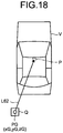
- FIG. 18 is a schematic diagram for explaining an example of the position of the virtual viewpoint in the bird's-eye view image generating system according to a seventh embodiment.
- processing performed by the viewpoint conversion processing unit 451 of the bird's-eye view image generation unit 45 is different from that in the bird's-eye view image generating system 1 according to the first embodiment and the sixth embodiment.
- the viewpoint conversion processing unit 451 In a case in which the obstacle Q acquired by the obstacle information acquisition unit 43 is positioned in the traveling direction of the vehicle V, the viewpoint conversion processing unit 451 generates an image obtained by performing viewpoint conversion processing to make a virtual viewpoint PG that is positioned right above the obstacle Q on an extension line L62 from the vehicle V to the obstacle Q.
- the viewpoint conversion processing unit 451 in a case in which the obstacle Q positioned on the rear side is detected, the viewpoint conversion processing unit 451 generates an image obtained by performing viewpoint conversion processing to make the virtual viewpoint PG that is positioned right above the obstacle Q.
- a position of the virtual viewpoint PG is represented as (xG, yG, zG).
- the virtual viewpoint PG is positioned on the left rear side of the vehicle V.
- the virtual viewpoint PG is positioned overlapping with the obstacle Q when viewed in the Z-axis direction.
- the virtual viewpoint PG is positioned on the left rear side of the virtual viewpoint P when viewed in the Z-axis direction.
- the virtual viewpoint PG is a viewpoint of obliquely looking down the vehicle V from right above the obstacle Q.
- the bird's-eye view image generating device 40 performs processing following the flowchart illustrated in FIG. 8 .
- the process at Step S16 is different from that in the first embodiment, and the processes at Step S11 to Step S15, Step S17, and Step S18 are the same as those in the first embodiment.
- the control unit 41 changes the position of the virtual viewpoint (Step S16). More specifically, the control unit 41 causes the bird's-eye view image generation unit 45 to generate a bird's-eye view image from the virtual viewpoint PG that is positioned on the extension line L62 from the vehicle V to the obstacle Q, and causes the display panel 30 to display the generated bird's-eye view image. The control unit 41 advances the process to Step S18.
- the bird's-eye view image from the virtual viewpoint PG is generated, the virtual viewpoint PG being positioned right above the obstacle Q on the extension line L62 from the vehicle V to the obstacle Q.
- the position of the virtual viewpoint can be changed to right above the obstacle Q to display the bird's-eye view image in which the relative positional relation between the obstacle Q and the vehicle V is represented more correctly. According to the present embodiment, whether the obstacle Q is brought into contact with the vehicle V can be easily and correctly recognized from the bird's-eye view image.
- the obstacle Q can be appropriately displayed in the bird's-eye view image. According to the present embodiment, visibility of the obstacle Q in the bird's-eye view image can be improved. According to the present embodiment, the obstacle Q around the vehicle can be displayed to be appropriately checked.
- the bird's-eye view image from the virtual viewpoint PG can be displayed as if a person guides the vehicle V coming closer to the obstacle Q while standing at the same position as the obstacle Q. Due to this, whether the obstacle Q is brought into contact with the vehicle V can be more intuitively recognized from the bird's-eye view image as compared with the bird's-eye view image 100 from the virtual viewpoint P that is positioned right above the vehicle V.
- FIG. 19 is a schematic diagram for explaining an example of the position of the virtual viewpoint in the bird's-eye view image generating system according to an eighth embodiment.
- FIG. 20 is a schematic diagram for explaining another example of the position of the virtual viewpoint in the bird's-eye view image generating system according to the eighth embodiment.
- FIG. 21 is a schematic diagram for explaining an example of the position of the virtual viewpoint in the bird's-eye view image generating system according to the eighth embodiment.
- processing performed by the viewpoint conversion processing unit 451 of the bird's-eye view image generation unit 45 is different from that in the bird's-eye view image generating system 1 according to the first embodiment and the sixth embodiment.
- the obstacle Q1 and the obstacle Q2 are present.
- the viewpoint conversion processing unit 451 performs viewpoint conversion processing on the periphery images acquired by the image data acquisition unit 42 to make a virtual viewpoint at a position that is determined based on respective extension lines from the vehicle V to a plurality of obstacles.
- the viewpoint conversion processing unit 451 in a case in which there is an obstacle satisfying a predetermined condition, the viewpoint conversion processing unit 451 generates an image obtained by performing viewpoint conversion processing on the periphery images to make a virtual viewpoint PH positioned on a bisector of an angle between any two of the respective extension lines from the vehicle V to the obstacles Q.
- the two extension lines may be, for example, extension lines having the largest angle therebetween.
- the two extension lines may be, for example, extension lines toward two obstacles Q the distances of which from the vehicle V are smaller than others.
- the viewpoint conversion processing unit 451 in a case in which a plurality of obstacles Q positioned on the left rear side of the vehicle V are detected, the viewpoint conversion processing unit 451 generates an image obtained by performing viewpoint conversion processing to make a virtual viewpoint PH1 positioned on a bisector L65 of an angle between an extension line L63 from the vehicle V to the obstacle Q1 and an extension line L64 from the vehicle V to the obstacle Q2.
- a position of the virtual viewpoint PH1 is represented as (xH1, yH1, zH1).
- the virtual viewpoint PH1 is positioned on the left rear side of the vehicle V.
- the virtual viewpoint PH1 is positioned on the rear side of the obstacle Q1 and on the left rear side of the obstacle Q2 when viewed in the Z-axis direction.
- the virtual viewpoint PH1 is positioned on the left rear side of the virtual viewpoint P when viewed in the Z-axis direction.
- the virtual viewpoint PH1 is separated from the center of the vehicle V by a distance larger than the distance between the center of the vehicle V and the obstacle Q1 and the distance between the center of the vehicle V and the obstacle Q2.
- the virtual viewpoint PH1 is a viewpoint of obliquely looking down the vehicle V from the left rear side.
- the viewpoint conversion processing unit 451 may generate a bird's-eye view image from a virtual viewpoint PH2 positioned on a bisector L68 of an angle between an extension line L66 from the center of the vehicle V to the obstacle Q1 and an extension line L67 from the center of the vehicle V to the obstacle Q2.
- a position of the virtual viewpoint PH2 is represented as (xH2, yH2, zH2).
- the virtual viewpoint PH2 is positioned on the right rear side of the vehicle V.
- the virtual viewpoint PH2 is positioned on the right rear side of the obstacle Q1 and on the rear side of the obstacle Q2 when viewed in the Z-axis direction.
- the virtual viewpoint PH2 is positioned on the right rear side of the virtual viewpoint P when viewed in the Z-axis direction.
- the virtual viewpoint PH2 is separated from the center of the vehicle V by a distance larger than the distance between the center of the vehicle V and the obstacle Q1 and the distance between the center of the vehicle V and the obstacle Q2.
- the virtual viewpoint PH2 is a viewpoint of obliquely looking down the vehicle V from the right rear side.
- the viewpoint conversion processing unit 451 may generate the bird's-eye view image from a virtual viewpoint PH3 positioned on a bisector L71 of an angle between an extension line L69 from the center of the vehicle V to the obstacle Q1 and an extension line L70 from the center of the vehicle V to the obstacle Q2.
- a position of the virtual viewpoint PH3 is represented as (xH3, yH3, zH3).
- the virtual viewpoint PH3 is positioned on the left rear side of the vehicle V.
- the virtual viewpoint PH3 is positioned on the left rear side of the obstacle Q1 and on the right rear side of the obstacle Q2 when viewed in the Z-axis direction.
- the virtual viewpoint PH3 is positioned on the left rear side of the virtual viewpoint P when viewed in the Z-axis direction.
- the virtual viewpoint PH3 is separated from the center of the vehicle V by a distance larger than the distance between the center of the vehicle V and the obstacle Q1 and the distance between the center of the vehicle V and the obstacle Q2.
- the virtual viewpoint PH3 is a viewpoint of obliquely looking down the vehicle V from the left rear side.
- the bird's-eye view image generating device 40 performs processing following the flowchart illustrated in FIG. 8 .
- the process at Step S16 is different from that in the first embodiment, and the processes at Step S11 to Step S15, Step S17, and Step S18 are the same as those in the first embodiment.
- the control unit 41 changes the position of the virtual viewpoint (Step S16). More specifically, the control unit 41 causes the bird's-eye view image generation unit 45 to generate the bird's-eye view image from the virtual viewpoint PH positioned on a bisector of an angle between any two of respective extension lines from the vehicle V to the obstacles Q, and causes the display panel 30 to display the generated bird's-eye view image.
- the control unit 41 advances the process to Step S18.
- the bird's-eye view image from the virtual viewpoint PH is generated, the virtual viewpoint PH positioned on the bisector of the angle between any two of the respective extension lines from the vehicle V to the obstacles Q. Due to this, according to the present embodiment, in a case in which the obstacles Q in the traveling direction are detected, the position of the virtual viewpoint can be changed to display the bird's-eye view image in which the obstacles Q do not overlap with each other and a relative positional relation among the obstacles Q and the vehicle V is represented. According to the present embodiment, whether the obstacles Q are brought into contact with the vehicle V can be easily recognized from the bird's-eye view image.
- the obstacles Q can be appropriately displayed in the bird's-eye view image. According to the present embodiment, visibility of the obstacles Q in the bird's-eye view image can be improved. According to the present embodiment, the obstacles Q around the vehicle can be displayed to be appropriately checked.
- the bird's-eye view image from the virtual viewpoint PH can be displayed as if a person guides the vehicle V coming closer to the obstacles Q while standing between the obstacles Q. Due to this, whether the obstacles Q are brought into contact with the vehicle V can be more easily recognized from the bird's-eye view image as compared with the bird's-eye view image 100 from the virtual viewpoint P that is positioned right above the vehicle V.
- FIG. 22 is a schematic diagram for explaining an example of the position of the virtual viewpoint in the bird's-eye view image generating system according to a ninth embodiment.
- processing performed by the bird's-eye view image generation unit 45 is different from that in the bird's-eye view image generating system 1 according to the first embodiment and the sixth embodiment.
- the obstacle Q1 is positioned on the left rear side of the vehicle V and the obstacle Q2 is positioned on the right rear side of the vehicle V.
- the bird's-eye view image generation unit 45 generates an image obtained by performing viewpoint conversion processing on the periphery images acquired by the image data acquisition unit 42 to make a virtual viewpoint PI1 different from the virtual viewpoint P so that the vehicle V and at least part of the obstacles Q can be overlooked based on the positional information of the obstacles Q acquired by the obstacle information acquisition unit 43. Additionally, the bird's-eye view image generation unit 45 generates an image obtained by performing viewpoint conversion processing on the periphery images to make a virtual viewpoint PI2 different from the virtual viewpoint PI1 so that the vehicle V and at least remaining part of the obstacles Q can be overlooked based on the positional information of the obstacles Q. The bird's-eye view image generation unit 45 then generates the bird's-eye view image by combining the two images subjected to the viewpoint conversion processing.
- the viewpoint conversion processing unit 451 In a case in which the obstacle Q1 positioned on the left rear side of the vehicle V and the obstacle Q2 positioned on the right rear side of the vehicle V are detected, the viewpoint conversion processing unit 451 generates an image obtained by performing viewpoint conversion processing to make the virtual viewpoint PI1 by changing the position of the virtual viewpoint to a position on an extension line L72 from the vehicle V to the obstacle Q1, and an image obtained by performing viewpoint conversion processing to make the virtual viewpoint PI2 by changing the position of the virtual viewpoint to a position on an extension line L73 from the vehicle V to the obstacle Q2.
- a position of the virtual viewpoint PI1 is represented as (xI1, yI1, zI1).
- a position of the virtual viewpoint PI2 is represented as (xI2, yI2, zI2).
- the virtual viewpoint PI1 is positioned on the left rear side of the vehicle V.
- the virtual viewpoint PI1 is positioned on the left rear side of the obstacle Q1 when viewed in the Z-axis direction.
- the virtual viewpoint PI1 is positioned on the left rear side of the virtual viewpoint P when viewed in the Z-axis direction.
- the virtual viewpoint PI1 is separated from the center of the vehicle V by a distance larger than the distance between the center of the vehicle V and the obstacle Q1.
- the virtual viewpoint PI1 is a viewpoint of obliquely looking down the vehicle V from the left rear side.
- the virtual viewpoint PI2 is positioned on the right rear side of the vehicle V.
- the virtual viewpoint PI2 is positioned on the right rear side of the obstacle Q2 when viewed in the Z-axis direction.
- the virtual viewpoint PI2 is positioned on the right rear side of the virtual viewpoint P when viewed in the Z-axis direction.
- the virtual viewpoint PI2 is separated from the center of the vehicle V by a distance larger than the distance between the center of the vehicle V and the obstacle Q2.
- the virtual viewpoint PI2 is a viewpoint of obliquely looking down the vehicle V from the right rear side.
- the combination processing unit 453 combines the image from the virtual viewpoint PI1 that has been subjected to viewpoint conversion processing and the image from the virtual viewpoint PI2 that has been subjected to viewpoint conversion processing to generate the bird's-eye view image. For example, the combination processing unit 453 generates the bird's-eye view image by combining the images so that the image from the virtual viewpoint PI1 that has been subjected to viewpoint conversion processing is displayed on the left side, and the image from the virtual viewpoint PI2 that has been subjected to viewpoint conversion processing is displayed on the right side.
- the bird's-eye view image generating device 40 performs processing following the flowchart illustrated in FIG. 8 .
- the process at Step S16 is different from that in the first embodiment, and the processes at Step S11 to Step S15, Step S17, and Step S18 are the same as those in the first embodiment.
- the control unit 41 changes the position of the virtual viewpoint (Step S16). More specifically, the control unit 41 causes the bird's-eye view image generation unit 45 to generate an image obtained by performing viewpoint conversion processing on the periphery images acquired by the image data acquisition unit 42 to make the virtual viewpoint PI1 different from the virtual viewpoint P so that the vehicle V and at least the obstacle Q1 can be overlooked based on the positional information of the obstacles Q acquired by the obstacle information acquisition unit 43.
- the control unit 41 causes the bird's-eye view image generation unit 45 to generate an image obtained by performing viewpoint conversion processing on the periphery images to make the virtual viewpoint PI2 different from the virtual viewpoint PI1 so that the vehicle V and at least the obstacle Q2 can be overlooked based on the positional information of the obstacles Q.
- the control unit 41 then causes the bird's-eye view image generation unit 45 to combine the two images to generate the bird's-eye view image, and causes the display panel 30 to display the generated bird's-eye view image.
- the control unit 41 advances the process to Step S18
- the image subjected to viewpoint conversion processing with a plurality of virtual viewpoints is generated.
- the images subjected to viewpoint conversion processing are combined to generate the bird's-eye view image.
- the images subjected to viewpoint conversion processing with a plurality of virtual viewpoints can be combined to display the bird's-eye view image in which a relative positional relation among the obstacles Q and the vehicle V is represented.
- the present embodiment even in a case in which the obstacles Q are detected on the left side and the right side in the traveling direction, for example, it is possible to display the bird's-eye view image obtained by combining the image from the virtual viewpoint PI1 and the image from the virtual viewpoint PI2 as if a person guides the vehicle V coming closer to the obstacles Q while standing in the rear of the respective obstacles Q. Whether the obstacles Q are brought into contact with the vehicle V can be appropriately recognized from the bird's-eye view image. In this way, according to the present embodiment, the obstacles Q can be appropriately displayed in the bird's-eye view image. According to the present embodiment, visibility of the obstacles Q in the bird's-eye view image can be improved. According to the present embodiment, the obstacle Q around the vehicle can be displayed to be appropriately checked.
- the bird's-eye view image generating system 1 has been described above, but the bird's-eye view image generating system 1 may be implemented in various different forms other than the embodiments described above.
- the components of the bird's-eye view image generating system 1 illustrated in the drawings are merely conceptual, and it is not required that they are physically configured as illustrated necessarily. That is, specific forms of the devices are not limited to those illustrated in the drawings. All or part thereof may be functionally or physically distributed or integrated in arbitrary units depending on a processing load, a usage state, and the like of the devices.
- the configuration of the bird's-eye view image generating system 1 is, for example, implemented as software such as a computer program loaded into a memory.
- the configuration is described as functional blocks implemented with such hardware and software cooperating with each other. That is, the functional blocks can be implemented in various forms with only hardware, only software, or a combination thereof.
- the components described above include a component that is easily conceivable by those skilled in the art, and substantially the same component.
- the configurations described above can be appropriately combined.
- the configurations can be variously omitted, replaced, or modified without departing from the gist of the present invention.
- the predetermined condition is that the obstacle Q is positioned in the traveling direction of the vehicle V, but the embodiment is not limited thereto.
- the predetermined condition may be, for example, that the obstacle Q may interfere with the vehicle V.
- the obstacle Q may interfere with the vehicle V
- the obstacle Q is positioned in the traveling direction of the vehicle V and has a height from the ground that may be brought into contact with the vehicle V.
- the embodiment is not limited thereto.
- the obstacle Q in a case in which the obstacle Q is positioned in the rear of the rear end of the vehicle V or in a case in which the obstacle Q is positioned in the rear of an axle position of a driving wheel of the vehicle V when the vehicle V moves backward, it may be determined that the predetermined condition is satisfied.
- control unit 41 may determine whether to start to display the bird's-eye view image depending on whether an operation of starting display of the bird's-eye view image for an operation unit is detected.
- the bird's-eye view image obtained by changing the position of the virtual viewpoint may be generated by shifting the center of the host vehicle icon from the center of the bird's-eye view image so that a display area in a direction in which the obstacle Q is detected is increased.
- the position of the virtual viewpoint P in the Z-direction may be, for example, at a height of a line of sight of a driver seated on a driver's seat, a height of a line of sight of the driver when he/she stands up, a height of a roof of the vehicle V, and the like.
Landscapes
- Engineering & Computer Science (AREA)
- Multimedia (AREA)
- Signal Processing (AREA)
- Physics & Mathematics (AREA)
- General Physics & Mathematics (AREA)
- Theoretical Computer Science (AREA)
- Mechanical Engineering (AREA)
- Closed-Circuit Television Systems (AREA)
- Image Processing (AREA)
Claims (6)
- Dispositif de génération d'images en vue à vol d'oiseau (40) comprenant :une unité d'acquisition de données d'image (42) configurée pour acquérir des données d'image d'environnement obtenues en photographiant un environnement d'un véhicule (V) ;une unité d'acquisition d'informations d'obstacle (43) configurée pour acquérir des informations de position d'obstacles (Q) détectés dans l'environnement du véhicule (V) ;une unité de génération d'image en vue à vol d'oiseau (45) configurée pour générer une image en vue à vol d'oiseau, dans un cas où il y a une pluralité d'obstacles (Q), obtenue en combinant des images de l'environnement acquises par l'unité d'acquisition de données d'image (42), les images de l'environnement ayant été soumises à un traitement de conversion de point de vue de sorte qu'un point de vue virtuel (P) soit positionné à une position où le point de vue virtuel (P) est séparé d'une position directement au-dessus du véhicule (V) de sorte que le point de vue virtuel (P) soit positionné à une position qui est déterminée sur la base de chacune de lignes d'extensions respectives allant du centre du véhicule (V) jusqu'aux obstacles (Q) de sorte que le véhicule (V) et une pluralité d'obstacles (Q) puissent être ignorés, sur la base des informations de position des obstacles (Q) acquises par l'unité d'acquisition d'informations d'obstacle (43) ; etune unité de commande d'affichage (48) configurée pour amener une unité d'affichage pour afficher l'image en vue à vol d'oiseau générée par l'unité de génération d'image en vue à vol d'oiseau (45),dans lequel l'unité de génération d'image en vue à vol d'oiseau génère en outre une image en vue à vol d'oiseau qui a été soumise à un traitement de conversion de point de vue de sorte que le point de vue virtuel (P) soit positionné sur une bissectrice d'un angle entre deux quelconques des lignes d'extension respectives allant du centre du véhicule (V) jusqu'aux obstacles (Q) à ignorer, ou positionné sur une bissectrice d'un angle entre deux quelconques des lignes directes respectives passant par le centre du véhicule, chacune orthogonale à des lignes d'extension respectives.
- Dispositif de génération d'images en vue à vol d'oiseau (40) selon la revendication 1, dans lequel le nombre d'obstacles est deux.
- Dispositif de génération d'images en vue à vol d'oiseau (40) selon la revendication 1, dans lequel, lorsque le point de vue virtuel (P) est positionné sur une bissectrice d'un angle entre deux quelconques des lignes d'extension respectives allant du centre du véhicule (V) jusqu'aux obstacles (Q), le point de vue virtuel (P) est séparé du centre du véhicule par une distance supérieure à la distance entre le centre du véhicule et les obstacles.
- Système de génération d'images en vue à vol d'oiseau (1) comprenant :le dispositif de génération d'images en vue à vol d'oiseau (40) selon l'une quelconque des revendications 1 à 3 ; etau moins un élément parmi une pluralité de caméras qui photographient l'environnement du véhicule (V), et une unité d'affichage et une unité de détection qui détecte un obstacle (Q) et fournit des informations d'obstacle.
- Procédé de génération d'images en vue à vol d'oiseau comprenant :une étape d'acquisition de données d'image d'acquisition des données d'image d'environnement obtenues en photographiant un environnement d'un véhicule (V) ;une étape d'acquisition d'informations d'obstacle d'acquisition d'informations de position d'une pluralité d'obstacles (Q) détectée dans l'environnement du véhicule (V) ;une étape de génération d'image en vue à vol d'oiseau de génération d'une image en vue à vol d'oiseau obtenue en combinant des images de l'environnement acquises à l'étape d'acquisition de données d'image, les images de l'environnement ayant été soumises à un traitement de conversion de point de vue de sorte qu'un point de vue virtuel (P) est positionné à une position où le point de vue virtuel (P) est séparé d'une position directement au-dessus du véhicule (V) et positionné à une position qui est déterminée sur la base de chacune de lignes d'extensions respectives allant du centre du véhicule (V) jusqu'aux obstacles (Q) de sorte que le véhicule (V) et une pluralité d'obstacles (Q) puissent être ignorés, sur la base des informations de position des obstacles (Q) acquises par l'étape d'acquisition d'informations d'obstacle ; etune étape de commande d'affichage pour amener une unité d'affichage à afficher l'image en vue à vol d'oiseau générée à l'étape de génération d'image en vue à vol d'oiseau,dans lequel l'unité de génération d'image en vue à vol d'oiseau génère en outre une image en vue à vol d'oiseau qui a été soumise à un traitement de conversion de point de vue de sorte que le point de vue virtuel (P) soit positionné sur une bissectrice d'un angle entre deux quelconques des lignes d'extension respectives allant du centre du véhicule (V) jusqu'aux obstacles (Q), ou positionné sur une bissectrice d'un angle entre deux quelconques des lignes directes respectives passant par le centre du véhicule, chacune orthogonale à des lignes d'extension respectives, etle point de vue virtuel (P) est séparé de la position par une distance supérieure à la distance entre le véhicule et les obstacles.
- Programme informatique comprenant des instructions qui, lorsque le programme est exécuté par un ordinateur fonctionnant comme un dispositif de génération d'images en vue à vol d'oiseau (40), amènent l'ordinateur à mettre en œuvre le procédé de génération d'image en vue à vol d'oiseau selon la revendication 5.
Applications Claiming Priority (3)
| Application Number | Priority Date | Filing Date | Title |
|---|---|---|---|
| JP2017036656A JP6760129B2 (ja) | 2017-02-28 | 2017-02-28 | 俯瞰映像生成装置、俯瞰映像生成システム、俯瞰映像生成方法およびプログラム |
| JP2017036657A JP6724821B2 (ja) | 2017-02-28 | 2017-02-28 | 俯瞰映像生成装置、俯瞰映像生成システム、俯瞰映像生成方法およびプログラム |
| PCT/JP2017/039953 WO2018159019A1 (fr) | 2017-02-28 | 2017-11-06 | Dispositif, système et procédé de génération d'image vidéo de vue à vol d'oiseau et programme associé |
Publications (3)
| Publication Number | Publication Date |
|---|---|
| EP3537714A1 EP3537714A1 (fr) | 2019-09-11 |
| EP3537714A4 EP3537714A4 (fr) | 2019-11-13 |
| EP3537714B1 true EP3537714B1 (fr) | 2021-08-25 |
Family
ID=63370796
Family Applications (1)
| Application Number | Title | Priority Date | Filing Date |
|---|---|---|---|
| EP17898960.4A Active EP3537714B1 (fr) | 2017-02-28 | 2017-11-06 | Dispositif, système et procédé de génération d'image vidéo de vue à vol d'oiseau et programme associé |
Country Status (3)
| Country | Link |
|---|---|
| US (1) | US10855934B2 (fr) |
| EP (1) | EP3537714B1 (fr) |
| WO (1) | WO2018159019A1 (fr) |
Families Citing this family (6)
| Publication number | Priority date | Publication date | Assignee | Title |
|---|---|---|---|---|
| JP6859906B2 (ja) * | 2017-09-06 | 2021-04-14 | トヨタ自動車株式会社 | 駐車支援装置 |
| JP7160701B2 (ja) * | 2019-01-23 | 2022-10-25 | 株式会社小松製作所 | 作業機械のシステム及び方法 |
| US11926263B2 (en) | 2019-04-18 | 2024-03-12 | Mitsubishi Electric Corporation | Vehicle surrounding area image generation device, vehicle surrounding area display system, and vehicle surrounding area display method |
| JP7323356B2 (ja) * | 2019-06-28 | 2023-08-08 | フォルシアクラリオン・エレクトロニクス株式会社 | 駐車支援装置及び駐車支援方法 |
| JP7543651B2 (ja) * | 2020-01-24 | 2024-09-03 | 株式会社Jvcケンウッド | 記録再生制御装置、再生制御装置、表示制御方法およびプログラム |
| KR20240111376A (ko) * | 2023-01-09 | 2024-07-17 | 현대자동차주식회사 | Svm 탑뷰 영상처리 방법 및 장치 |
Family Cites Families (11)
| Publication number | Priority date | Publication date | Assignee | Title |
|---|---|---|---|---|
| JP3300334B2 (ja) * | 1999-04-16 | 2002-07-08 | 松下電器産業株式会社 | 画像処理装置および監視システム |
| WO2000064175A1 (fr) | 1999-04-16 | 2000-10-26 | Matsushita Electric Industrial Co., Ltd. | Dispositif de traitement d'images et systeme de surveillance |
| US7369041B2 (en) * | 2004-04-27 | 2008-05-06 | Matsushita Electric Industrial Co., Ltd. | Vehicle surrounding display device |
| JP4458138B2 (ja) * | 2007-09-18 | 2010-04-28 | 株式会社デンソー | 車両周辺監視装置 |
| EP2285109B1 (fr) * | 2008-05-29 | 2018-11-28 | Fujitsu Limited | Processeur d'image de véhicule et système de traitement d'image de véhicule |
| JP5182042B2 (ja) * | 2008-11-28 | 2013-04-10 | 富士通株式会社 | 画像処理装置、画像処理方法及びコンピュータプログラム |
| JP5439890B2 (ja) * | 2009-03-25 | 2014-03-12 | 富士通株式会社 | 画像処理方法、画像処理装置及びプログラム |
| JP5604146B2 (ja) * | 2010-03-25 | 2014-10-08 | 富士通テン株式会社 | 車載照明装置、画像処理装置、画像表示システム及び照明方法 |
| JP5741173B2 (ja) | 2011-04-19 | 2015-07-01 | トヨタ自動車株式会社 | 画像表示装置、及び、画像表示方法 |
| JP5979505B2 (ja) * | 2011-08-26 | 2016-08-24 | パナソニックIpマネジメント株式会社 | 運転支援装置 |
| WO2016031009A1 (fr) * | 2014-08-28 | 2016-03-03 | 国立大学法人東京大学 | Système d'affichage d'engin de chantier, dispositif de commande d'affichage, engin de chantier et procédé de commande d'affichage |
-
2017
- 2017-11-06 WO PCT/JP2017/039953 patent/WO2018159019A1/fr unknown
- 2017-11-06 EP EP17898960.4A patent/EP3537714B1/fr active Active
-
2019
- 2019-03-19 US US16/357,473 patent/US10855934B2/en active Active
Non-Patent Citations (1)
| Title |
|---|
| None * |
Also Published As
| Publication number | Publication date |
|---|---|
| EP3537714A4 (fr) | 2019-11-13 |
| US20190215465A1 (en) | 2019-07-11 |
| WO2018159019A1 (fr) | 2018-09-07 |
| US10855934B2 (en) | 2020-12-01 |
| EP3537714A1 (fr) | 2019-09-11 |
Similar Documents
| Publication | Publication Date | Title |
|---|---|---|
| EP3537714B1 (fr) | Dispositif, système et procédé de génération d'image vidéo de vue à vol d'oiseau et programme associé | |
| EP3650285A1 (fr) | Procédé et dispositif d'aide au stationnement | |
| JP6730613B2 (ja) | 俯瞰映像生成装置、俯瞰映像生成システム、俯瞰映像生成方法およびプログラム | |
| US20160350602A1 (en) | Parking camera system and method of driving the same | |
| JP5633376B2 (ja) | 駐車支援システム | |
| US20130293683A1 (en) | System and method of interactively controlling a virtual camera | |
| US20110001819A1 (en) | Image Processing Apparatus | |
| KR20150116116A (ko) | 차량 주변 이미지 생성 장치 및 방법 | |
| KR20190047027A (ko) | 차량의 차량 주변 리어뷰 미러 조망을 제공하는 방법 | |
| WO2018159017A1 (fr) | Dispositif de commande d'affichage de véhicule, système d'affichage de véhicule, programme et procédé de commande d'affichage de véhicule | |
| CN107438538A (zh) | 用于显示车辆的车辆周围环境的方法 | |
| US10609337B2 (en) | Image processing apparatus | |
| CN106794798A (zh) | 图像生成装置以及图像生成方法 | |
| JP6778620B2 (ja) | 区画線検出装置、区画線検出システム、及び区画線検出方法 | |
| JP2010208359A (ja) | 車両用表示装置 | |
| WO2015122124A1 (fr) | Appareil d'affichage d'image de périphérie de véhicule et procédé d'affichage d'image de périphérie de véhicule | |
| JP2010039953A (ja) | 運転支援装置 | |
| JP5861449B2 (ja) | 障害物警報装置 | |
| JP5845909B2 (ja) | 障害物警報装置 | |
| JP5853206B2 (ja) | 車載用表示装置 | |
| JP2010073036A (ja) | 車両周辺監視装置 | |
| JP6760129B2 (ja) | 俯瞰映像生成装置、俯瞰映像生成システム、俯瞰映像生成方法およびプログラム | |
| Yoshida et al. | Transparent cockpit: Visual assistance system for vehicle using retro-reflective projection technology | |
| JP6724821B2 (ja) | 俯瞰映像生成装置、俯瞰映像生成システム、俯瞰映像生成方法およびプログラム | |
| KR20130031653A (ko) | 차량용 후방감지 카메라의 시야각 조절 시스템 |
Legal Events
| Date | Code | Title | Description |
|---|---|---|---|
| STAA | Information on the status of an ep patent application or granted ep patent |
Free format text: STATUS: THE INTERNATIONAL PUBLICATION HAS BEEN MADE |
|
| PUAI | Public reference made under article 153(3) epc to a published international application that has entered the european phase |
Free format text: ORIGINAL CODE: 0009012 |
|
| STAA | Information on the status of an ep patent application or granted ep patent |
Free format text: STATUS: REQUEST FOR EXAMINATION WAS MADE |
|
| 17P | Request for examination filed |
Effective date: 20190606 |
|
| AK | Designated contracting states |
Kind code of ref document: A1 Designated state(s): AL AT BE BG CH CY CZ DE DK EE ES FI FR GB GR HR HU IE IS IT LI LT LU LV MC MK MT NL NO PL PT RO RS SE SI SK SM TR |
|
| AX | Request for extension of the european patent |
Extension state: BA ME |
|
| A4 | Supplementary search report drawn up and despatched |
Effective date: 20191016 |
|
| RIC1 | Information provided on ipc code assigned before grant |
Ipc: G06T 11/00 20060101ALI20191010BHEP Ipc: B60R 11/02 20060101ALI20191010BHEP Ipc: B60R 1/00 20060101ALI20191010BHEP Ipc: H04N 7/18 20060101AFI20191010BHEP |
|
| DAV | Request for validation of the european patent (deleted) | ||
| DAX | Request for extension of the european patent (deleted) | ||
| STAA | Information on the status of an ep patent application or granted ep patent |
Free format text: STATUS: EXAMINATION IS IN PROGRESS |
|
| 17Q | First examination report despatched |
Effective date: 20200727 |
|
| STAA | Information on the status of an ep patent application or granted ep patent |
Free format text: STATUS: EXAMINATION IS IN PROGRESS |
|
| GRAP | Despatch of communication of intention to grant a patent |
Free format text: ORIGINAL CODE: EPIDOSNIGR1 |
|
| STAA | Information on the status of an ep patent application or granted ep patent |
Free format text: STATUS: GRANT OF PATENT IS INTENDED |
|
| INTG | Intention to grant announced |
Effective date: 20210317 |
|
| GRAS | Grant fee paid |
Free format text: ORIGINAL CODE: EPIDOSNIGR3 |
|
| GRAA | (expected) grant |
Free format text: ORIGINAL CODE: 0009210 |
|
| STAA | Information on the status of an ep patent application or granted ep patent |
Free format text: STATUS: THE PATENT HAS BEEN GRANTED |
|
| AK | Designated contracting states |
Kind code of ref document: B1 Designated state(s): AL AT BE BG CH CY CZ DE DK EE ES FI FR GB GR HR HU IE IS IT LI LT LU LV MC MK MT NL NO PL PT RO RS SE SI SK SM TR |
|
| REG | Reference to a national code |
Ref country code: CH Ref legal event code: EP |
|
| REG | Reference to a national code |
Ref country code: IE Ref legal event code: FG4D Ref country code: AT Ref legal event code: REF Ref document number: 1425023 Country of ref document: AT Kind code of ref document: T Effective date: 20210915 |
|
| REG | Reference to a national code |
Ref country code: DE Ref legal event code: R096 Ref document number: 602017044962 Country of ref document: DE |
|
| REG | Reference to a national code |
Ref country code: LT Ref legal event code: MG9D |
|
| REG | Reference to a national code |
Ref country code: NL Ref legal event code: MP Effective date: 20210825 |
|
| REG | Reference to a national code |
Ref country code: AT Ref legal event code: MK05 Ref document number: 1425023 Country of ref document: AT Kind code of ref document: T Effective date: 20210825 |
|
| PG25 | Lapsed in a contracting state [announced via postgrant information from national office to epo] |
Ref country code: PT Free format text: LAPSE BECAUSE OF FAILURE TO SUBMIT A TRANSLATION OF THE DESCRIPTION OR TO PAY THE FEE WITHIN THE PRESCRIBED TIME-LIMIT Effective date: 20211227 Ref country code: NO Free format text: LAPSE BECAUSE OF FAILURE TO SUBMIT A TRANSLATION OF THE DESCRIPTION OR TO PAY THE FEE WITHIN THE PRESCRIBED TIME-LIMIT Effective date: 20211125 Ref country code: BG Free format text: LAPSE BECAUSE OF FAILURE TO SUBMIT A TRANSLATION OF THE DESCRIPTION OR TO PAY THE FEE WITHIN THE PRESCRIBED TIME-LIMIT Effective date: 20211125 Ref country code: AT Free format text: LAPSE BECAUSE OF FAILURE TO SUBMIT A TRANSLATION OF THE DESCRIPTION OR TO PAY THE FEE WITHIN THE PRESCRIBED TIME-LIMIT Effective date: 20210825 Ref country code: LT Free format text: LAPSE BECAUSE OF FAILURE TO SUBMIT A TRANSLATION OF THE DESCRIPTION OR TO PAY THE FEE WITHIN THE PRESCRIBED TIME-LIMIT Effective date: 20210825 Ref country code: SE Free format text: LAPSE BECAUSE OF FAILURE TO SUBMIT A TRANSLATION OF THE DESCRIPTION OR TO PAY THE FEE WITHIN THE PRESCRIBED TIME-LIMIT Effective date: 20210825 Ref country code: RS Free format text: LAPSE BECAUSE OF FAILURE TO SUBMIT A TRANSLATION OF THE DESCRIPTION OR TO PAY THE FEE WITHIN THE PRESCRIBED TIME-LIMIT Effective date: 20210825 Ref country code: FI Free format text: LAPSE BECAUSE OF FAILURE TO SUBMIT A TRANSLATION OF THE DESCRIPTION OR TO PAY THE FEE WITHIN THE PRESCRIBED TIME-LIMIT Effective date: 20210825 Ref country code: ES Free format text: LAPSE BECAUSE OF FAILURE TO SUBMIT A TRANSLATION OF THE DESCRIPTION OR TO PAY THE FEE WITHIN THE PRESCRIBED TIME-LIMIT Effective date: 20210825 Ref country code: HR Free format text: LAPSE BECAUSE OF FAILURE TO SUBMIT A TRANSLATION OF THE DESCRIPTION OR TO PAY THE FEE WITHIN THE PRESCRIBED TIME-LIMIT Effective date: 20210825 |
|
| PG25 | Lapsed in a contracting state [announced via postgrant information from national office to epo] |
Ref country code: PL Free format text: LAPSE BECAUSE OF FAILURE TO SUBMIT A TRANSLATION OF THE DESCRIPTION OR TO PAY THE FEE WITHIN THE PRESCRIBED TIME-LIMIT Effective date: 20210825 Ref country code: LV Free format text: LAPSE BECAUSE OF FAILURE TO SUBMIT A TRANSLATION OF THE DESCRIPTION OR TO PAY THE FEE WITHIN THE PRESCRIBED TIME-LIMIT Effective date: 20210825 Ref country code: GR Free format text: LAPSE BECAUSE OF FAILURE TO SUBMIT A TRANSLATION OF THE DESCRIPTION OR TO PAY THE FEE WITHIN THE PRESCRIBED TIME-LIMIT Effective date: 20211126 |
|
| PG25 | Lapsed in a contracting state [announced via postgrant information from national office to epo] |
Ref country code: NL Free format text: LAPSE BECAUSE OF FAILURE TO SUBMIT A TRANSLATION OF THE DESCRIPTION OR TO PAY THE FEE WITHIN THE PRESCRIBED TIME-LIMIT Effective date: 20210825 |
|
| PG25 | Lapsed in a contracting state [announced via postgrant information from national office to epo] |
Ref country code: DK Free format text: LAPSE BECAUSE OF FAILURE TO SUBMIT A TRANSLATION OF THE DESCRIPTION OR TO PAY THE FEE WITHIN THE PRESCRIBED TIME-LIMIT Effective date: 20210825 |
|
| REG | Reference to a national code |
Ref country code: DE Ref legal event code: R097 Ref document number: 602017044962 Country of ref document: DE |
|
| PG25 | Lapsed in a contracting state [announced via postgrant information from national office to epo] |
Ref country code: SM Free format text: LAPSE BECAUSE OF FAILURE TO SUBMIT A TRANSLATION OF THE DESCRIPTION OR TO PAY THE FEE WITHIN THE PRESCRIBED TIME-LIMIT Effective date: 20210825 Ref country code: SK Free format text: LAPSE BECAUSE OF FAILURE TO SUBMIT A TRANSLATION OF THE DESCRIPTION OR TO PAY THE FEE WITHIN THE PRESCRIBED TIME-LIMIT Effective date: 20210825 Ref country code: RO Free format text: LAPSE BECAUSE OF FAILURE TO SUBMIT A TRANSLATION OF THE DESCRIPTION OR TO PAY THE FEE WITHIN THE PRESCRIBED TIME-LIMIT Effective date: 20210825 Ref country code: EE Free format text: LAPSE BECAUSE OF FAILURE TO SUBMIT A TRANSLATION OF THE DESCRIPTION OR TO PAY THE FEE WITHIN THE PRESCRIBED TIME-LIMIT Effective date: 20210825 Ref country code: CZ Free format text: LAPSE BECAUSE OF FAILURE TO SUBMIT A TRANSLATION OF THE DESCRIPTION OR TO PAY THE FEE WITHIN THE PRESCRIBED TIME-LIMIT Effective date: 20210825 Ref country code: AL Free format text: LAPSE BECAUSE OF FAILURE TO SUBMIT A TRANSLATION OF THE DESCRIPTION OR TO PAY THE FEE WITHIN THE PRESCRIBED TIME-LIMIT Effective date: 20210825 |
|
| PG25 | Lapsed in a contracting state [announced via postgrant information from national office to epo] |
Ref country code: MC Free format text: LAPSE BECAUSE OF FAILURE TO SUBMIT A TRANSLATION OF THE DESCRIPTION OR TO PAY THE FEE WITHIN THE PRESCRIBED TIME-LIMIT Effective date: 20210825 |
|
| REG | Reference to a national code |
Ref country code: CH Ref legal event code: PL |
|
| PLBE | No opposition filed within time limit |
Free format text: ORIGINAL CODE: 0009261 |
|
| STAA | Information on the status of an ep patent application or granted ep patent |
Free format text: STATUS: NO OPPOSITION FILED WITHIN TIME LIMIT |
|
| GBPC | Gb: european patent ceased through non-payment of renewal fee |
Effective date: 20211125 |
|
| PG25 | Lapsed in a contracting state [announced via postgrant information from national office to epo] |
Ref country code: LU Free format text: LAPSE BECAUSE OF NON-PAYMENT OF DUE FEES Effective date: 20211106 Ref country code: IT Free format text: LAPSE BECAUSE OF FAILURE TO SUBMIT A TRANSLATION OF THE DESCRIPTION OR TO PAY THE FEE WITHIN THE PRESCRIBED TIME-LIMIT Effective date: 20210825 Ref country code: BE Free format text: LAPSE BECAUSE OF NON-PAYMENT OF DUE FEES Effective date: 20211130 |
|
| REG | Reference to a national code |
Ref country code: BE Ref legal event code: MM Effective date: 20211130 |
|
| 26N | No opposition filed |
Effective date: 20220527 |
|
| PG25 | Lapsed in a contracting state [announced via postgrant information from national office to epo] |
Ref country code: SI Free format text: LAPSE BECAUSE OF FAILURE TO SUBMIT A TRANSLATION OF THE DESCRIPTION OR TO PAY THE FEE WITHIN THE PRESCRIBED TIME-LIMIT Effective date: 20210825 Ref country code: LI Free format text: LAPSE BECAUSE OF NON-PAYMENT OF DUE FEES Effective date: 20211130 Ref country code: CH Free format text: LAPSE BECAUSE OF NON-PAYMENT OF DUE FEES Effective date: 20211130 |
|
| PG25 | Lapsed in a contracting state [announced via postgrant information from national office to epo] |
Ref country code: IE Free format text: LAPSE BECAUSE OF NON-PAYMENT OF DUE FEES Effective date: 20211106 Ref country code: GB Free format text: LAPSE BECAUSE OF NON-PAYMENT OF DUE FEES Effective date: 20211125 |
|
| PG25 | Lapsed in a contracting state [announced via postgrant information from national office to epo] |
Ref country code: FR Free format text: LAPSE BECAUSE OF NON-PAYMENT OF DUE FEES Effective date: 20211130 |
|
| PG25 | Lapsed in a contracting state [announced via postgrant information from national office to epo] |
Ref country code: CY Free format text: LAPSE BECAUSE OF FAILURE TO SUBMIT A TRANSLATION OF THE DESCRIPTION OR TO PAY THE FEE WITHIN THE PRESCRIBED TIME-LIMIT Effective date: 20210825 |
|
| PG25 | Lapsed in a contracting state [announced via postgrant information from national office to epo] |
Ref country code: HU Free format text: LAPSE BECAUSE OF FAILURE TO SUBMIT A TRANSLATION OF THE DESCRIPTION OR TO PAY THE FEE WITHIN THE PRESCRIBED TIME-LIMIT; INVALID AB INITIO Effective date: 20171106 |
|
| PGFP | Annual fee paid to national office [announced via postgrant information from national office to epo] |
Ref country code: DE Payment date: 20230929 Year of fee payment: 7 |
|
| PG25 | Lapsed in a contracting state [announced via postgrant information from national office to epo] |
Ref country code: MK Free format text: LAPSE BECAUSE OF FAILURE TO SUBMIT A TRANSLATION OF THE DESCRIPTION OR TO PAY THE FEE WITHIN THE PRESCRIBED TIME-LIMIT Effective date: 20210825 |
|
| PG25 | Lapsed in a contracting state [announced via postgrant information from national office to epo] |
Ref country code: TR Free format text: LAPSE BECAUSE OF FAILURE TO SUBMIT A TRANSLATION OF THE DESCRIPTION OR TO PAY THE FEE WITHIN THE PRESCRIBED TIME-LIMIT Effective date: 20210825 |
|
| PG25 | Lapsed in a contracting state [announced via postgrant information from national office to epo] |
Ref country code: MT Free format text: LAPSE BECAUSE OF FAILURE TO SUBMIT A TRANSLATION OF THE DESCRIPTION OR TO PAY THE FEE WITHIN THE PRESCRIBED TIME-LIMIT Effective date: 20210825 |