EP3537609A1 - Verfahren zum anwenden von überlagerter schwingung und analog-digital-wandler gemäss dem verfahren - Google Patents
Verfahren zum anwenden von überlagerter schwingung und analog-digital-wandler gemäss dem verfahren Download PDFInfo
- Publication number
- EP3537609A1 EP3537609A1 EP19161602.8A EP19161602A EP3537609A1 EP 3537609 A1 EP3537609 A1 EP 3537609A1 EP 19161602 A EP19161602 A EP 19161602A EP 3537609 A1 EP3537609 A1 EP 3537609A1
- Authority
- EP
- European Patent Office
- Prior art keywords
- dither
- digital
- analog
- value
- stage
- Prior art date
- Legal status (The legal status is an assumption and is not a legal conclusion. Google has not performed a legal analysis and makes no representation as to the accuracy of the status listed.)
- Granted
Links
- 238000000034 method Methods 0.000 title claims description 55
- 238000005070 sampling Methods 0.000 claims description 184
- 239000003990 capacitor Substances 0.000 claims description 91
- 238000006243 chemical reaction Methods 0.000 claims description 57
- 230000008569 process Effects 0.000 claims description 7
- 230000004044 response Effects 0.000 abstract description 8
- 230000015572 biosynthetic process Effects 0.000 abstract 1
- 229920005994 diacetyl cellulose Polymers 0.000 description 32
- 238000010586 diagram Methods 0.000 description 15
- 230000006870 function Effects 0.000 description 13
- 230000007704 transition Effects 0.000 description 12
- 238000013459 approach Methods 0.000 description 11
- 230000008859 change Effects 0.000 description 9
- 230000008901 benefit Effects 0.000 description 6
- 230000000694 effects Effects 0.000 description 6
- 238000005516 engineering process Methods 0.000 description 6
- 230000010363 phase shift Effects 0.000 description 6
- 238000003491 array Methods 0.000 description 5
- 239000000872 buffer Substances 0.000 description 5
- 101100434411 Saccharomyces cerevisiae (strain ATCC 204508 / S288c) ADH1 gene Proteins 0.000 description 4
- 101150102866 adc1 gene Proteins 0.000 description 4
- 239000004020 conductor Substances 0.000 description 4
- 230000004048 modification Effects 0.000 description 4
- 238000012986 modification Methods 0.000 description 4
- 230000009467 reduction Effects 0.000 description 4
- 238000013139 quantization Methods 0.000 description 3
- 101150042711 adc2 gene Proteins 0.000 description 2
- 230000004075 alteration Effects 0.000 description 2
- 230000003321 amplification Effects 0.000 description 2
- 238000012937 correction Methods 0.000 description 2
- 238000013461 design Methods 0.000 description 2
- 230000006872 improvement Effects 0.000 description 2
- 238000002347 injection Methods 0.000 description 2
- 239000007924 injection Substances 0.000 description 2
- 238000004859 neutralization-reionization mass spectrometry Methods 0.000 description 2
- 238000003199 nucleic acid amplification method Methods 0.000 description 2
- 238000006467 substitution reaction Methods 0.000 description 2
- WQZGKKKJIJFFOK-GASJEMHNSA-N Glucose Natural products OC[C@H]1OC(O)[C@H](O)[C@@H](O)[C@@H]1O WQZGKKKJIJFFOK-GASJEMHNSA-N 0.000 description 1
- 230000032683 aging Effects 0.000 description 1
- 239000008280 blood Substances 0.000 description 1
- 210000004369 blood Anatomy 0.000 description 1
- 238000004364 calculation method Methods 0.000 description 1
- 238000010276 construction Methods 0.000 description 1
- 230000001419 dependent effect Effects 0.000 description 1
- 230000009977 dual effect Effects 0.000 description 1
- 230000001747 exhibiting effect Effects 0.000 description 1
- 239000008103 glucose Substances 0.000 description 1
- 238000010348 incorporation Methods 0.000 description 1
- 230000003993 interaction Effects 0.000 description 1
- 238000001459 lithography Methods 0.000 description 1
- 238000004519 manufacturing process Methods 0.000 description 1
- 238000005259 measurement Methods 0.000 description 1
- 230000007246 mechanism Effects 0.000 description 1
- 238000012544 monitoring process Methods 0.000 description 1
- 230000003071 parasitic effect Effects 0.000 description 1
- 239000004065 semiconductor Substances 0.000 description 1
- 239000000243 solution Substances 0.000 description 1
- 230000035882 stress Effects 0.000 description 1
- 239000000126 substance Substances 0.000 description 1
- 230000002123 temporal effect Effects 0.000 description 1
Images


Classifications
-
- H—ELECTRICITY
- H03—ELECTRONIC CIRCUITRY
- H03M—CODING; DECODING; CODE CONVERSION IN GENERAL
- H03M1/00—Analogue/digital conversion; Digital/analogue conversion
- H03M1/12—Analogue/digital converters
- H03M1/34—Analogue value compared with reference values
- H03M1/345—Analogue value compared with reference values for direct conversion to a residue number representation
-
- H—ELECTRICITY
- H03—ELECTRONIC CIRCUITRY
- H03M—CODING; DECODING; CODE CONVERSION IN GENERAL
- H03M1/00—Analogue/digital conversion; Digital/analogue conversion
- H03M1/06—Continuously compensating for, or preventing, undesired influence of physical parameters
- H03M1/0617—Continuously compensating for, or preventing, undesired influence of physical parameters characterised by the use of methods or means not specific to a particular type of detrimental influence
- H03M1/0634—Continuously compensating for, or preventing, undesired influence of physical parameters characterised by the use of methods or means not specific to a particular type of detrimental influence by averaging out the errors, e.g. using sliding scale
- H03M1/0636—Continuously compensating for, or preventing, undesired influence of physical parameters characterised by the use of methods or means not specific to a particular type of detrimental influence by averaging out the errors, e.g. using sliding scale in the amplitude domain
- H03M1/0639—Continuously compensating for, or preventing, undesired influence of physical parameters characterised by the use of methods or means not specific to a particular type of detrimental influence by averaging out the errors, e.g. using sliding scale in the amplitude domain using dither, e.g. using triangular or sawtooth waveforms
- H03M1/0641—Continuously compensating for, or preventing, undesired influence of physical parameters characterised by the use of methods or means not specific to a particular type of detrimental influence by averaging out the errors, e.g. using sliding scale in the amplitude domain using dither, e.g. using triangular or sawtooth waveforms the dither being a random signal
-
- H—ELECTRICITY
- H03—ELECTRONIC CIRCUITRY
- H03M—CODING; DECODING; CODE CONVERSION IN GENERAL
- H03M1/00—Analogue/digital conversion; Digital/analogue conversion
- H03M1/12—Analogue/digital converters
- H03M1/124—Sampling or signal conditioning arrangements specially adapted for A/D converters
- H03M1/1245—Details of sampling arrangements or methods
- H03M1/1265—Non-uniform sampling
- H03M1/128—Non-uniform sampling at random intervals, e.g. digital alias free signal processing [DASP]
-
- H—ELECTRICITY
- H03—ELECTRONIC CIRCUITRY
- H03M—CODING; DECODING; CODE CONVERSION IN GENERAL
- H03M1/00—Analogue/digital conversion; Digital/analogue conversion
- H03M1/12—Analogue/digital converters
- H03M1/14—Conversion in steps with each step involving the same or a different conversion means and delivering more than one bit
- H03M1/16—Conversion in steps with each step involving the same or a different conversion means and delivering more than one bit with scale factor modification, i.e. by changing the amplification between the steps
- H03M1/164—Conversion in steps with each step involving the same or a different conversion means and delivering more than one bit with scale factor modification, i.e. by changing the amplification between the steps the steps being performed sequentially in series-connected stages
- H03M1/165—Conversion in steps with each step involving the same or a different conversion means and delivering more than one bit with scale factor modification, i.e. by changing the amplification between the steps the steps being performed sequentially in series-connected stages in which two or more residues with respect to different reference levels in a stage are used as input signals for the next stage, i.e. multi-residue type
-
- H—ELECTRICITY
- H03—ELECTRONIC CIRCUITRY
- H03M—CODING; DECODING; CODE CONVERSION IN GENERAL
- H03M1/00—Analogue/digital conversion; Digital/analogue conversion
- H03M1/12—Analogue/digital converters
- H03M1/20—Increasing resolution using an n bit system to obtain n + m bits
- H03M1/201—Increasing resolution using an n bit system to obtain n + m bits by dithering
-
- H—ELECTRICITY
- H03—ELECTRONIC CIRCUITRY
- H03M—CODING; DECODING; CODE CONVERSION IN GENERAL
- H03M1/00—Analogue/digital conversion; Digital/analogue conversion
- H03M1/12—Analogue/digital converters
- H03M1/34—Analogue value compared with reference values
- H03M1/38—Analogue value compared with reference values sequentially only, e.g. successive approximation type
- H03M1/46—Analogue value compared with reference values sequentially only, e.g. successive approximation type with digital/analogue converter for supplying reference values to converter
- H03M1/466—Analogue value compared with reference values sequentially only, e.g. successive approximation type with digital/analogue converter for supplying reference values to converter using switched capacitors
- H03M1/468—Analogue value compared with reference values sequentially only, e.g. successive approximation type with digital/analogue converter for supplying reference values to converter using switched capacitors in which the input S/H circuit is merged with the feedback DAC array
-
- H—ELECTRICITY
- H03—ELECTRONIC CIRCUITRY
- H03M—CODING; DECODING; CODE CONVERSION IN GENERAL
- H03M1/00—Analogue/digital conversion; Digital/analogue conversion
- H03M1/66—Digital/analogue converters
- H03M1/68—Digital/analogue converters with conversions of different sensitivity, i.e. one conversion relating to the more significant digital bits and another conversion to the less significant bits
- H03M1/687—Segmented, i.e. the more significant bit converter being of the unary decoded type and the less significant bit converter being of the binary weighted type
-
- H—ELECTRICITY
- H03—ELECTRONIC CIRCUITRY
- H03M—CODING; DECODING; CODE CONVERSION IN GENERAL
- H03M1/00—Analogue/digital conversion; Digital/analogue conversion
- H03M1/66—Digital/analogue converters
- H03M1/74—Simultaneous conversion
- H03M1/80—Simultaneous conversion using weighted impedances
- H03M1/802—Simultaneous conversion using weighted impedances using capacitors, e.g. neuron-mos transistors, charge coupled devices
- H03M1/804—Simultaneous conversion using weighted impedances using capacitors, e.g. neuron-mos transistors, charge coupled devices with charge redistribution
Definitions
- the present disclosure relates to improvements in analog to digital converters.
- ADCs Analog to digital converters
- ADCs are used to convert signals from the real world to the digital domain, the signals being obtained from, for example, cameras, microphones, temperature sensors, pressure sensors, position transducers, gas-flow sensors, electro-chemical cells (e.g., for blood glucose monitoring), and many other forms of transducer.
- Those real world measurements are converted into digital values that can be processed by computers, micro-processors, and the like.
- Parameters of ADCs include how fast they are, how finely they can distinguish changes in the input signal (i.e., their resolution), and how linear they are. Ideally, all single bit transitions in the output word of an ADC would equate to a fixed size transition in the analog input signal presented to the ADC. In reality, this is very hard to achieve.
- Non-linearity in an analog to digital converter can be improved by dithering the ADC.
- a non-linearity is smeared out over several digital codes of the ADC by the application of the dither, thereby reducing the severity of the non-linearity at any given ADC output code.
- the dither value can then be subtracted such that the digital value of the ADC output signal (the conversion result) is not affected by the dither, but the performance of the ADC is improved.
- speed is one of the parameters of the ADC.
- the task of converting a signal may be shared between two or more series connected stages. Such an arrangement is known as a pipeline.
- a stage of a pipeline performs part of the analog to digital conversion.
- a stage may also form a residue, which represents a difference between the analog signal the stage received and the analog value equivalent to digital conversion result of the stage.
- the residue is passed to a subsequent stage of the pipeline.
- the subsequent stage performs an analog to digital conversion of the residue.
- a method of operating a residue forming stage of an analog to digital converter comprising an analog to digital converter and at least a first sampling digital to analog converter (DAC).
- the analog to digital converter of the residue forming stage has a least significant bit value, representing the limit of resolution of the stage.
- the method comprises receiving an input signal to be converted and adding a first dither value to the input signal to form a dithered input signal which is sampled by the at least first sampling digital to analog converter. However, the first dither value is not added to the input signal provided to the analog to digital converter of the stage.
- a different dither i.e., a second dither value can be applied to the signal provided to the analog to digital converter.
- the method further comprises using the analog to digital converter of the stage to form a digital code representing the input signal and removing at least part of the first dither.
- the removing of at least part of the first dither may be performed by: (a) modifying the digital code by a digital value representative of or based on at least part of the first dither value to form a modified digital code, and providing the modified digital code to the at least one sampling digital to analog converter; and/or (b) passing at least part of the dither to a subsequent analog to digital converter stage that it receives a residue from the sampling digital to analog converter, the dither being subtracted from a digital output result of the subsequent analog to digital converter stage.
- the analog to digital converter of the stage may include an ADC operated in accordance with a suitable conversion strategy, such as (but not limited to) a successive approximation register (SAR) conversion scheme.
- a suitable conversion strategy such as (but not limited to) a successive approximation register (SAR) conversion scheme.
- SAR successive approximation register
- Other technologies may, for example, include Flash converters, ramp converters, and sigma-delta converters.
- the ADC of the stage may be a combination of ADC technologies, such as a Flash ADC to quickly resolve a few of the most significant bits of the input signal, and to provide a partial result to a further converter technology that resolves the rest of the conversion result output by the stage.
- the ADC of the stage could be formed of a single technology such as a Flash converter or a sigma-delta converter.
- the sampling DAC may be formed as a combination of a sampling circuit including a sampling capacitor and associated switches for performing a sample and hold or track and hold function, and a cooperating DAC.
- the sampling circuit and the DAC are coupled together such that a difference can be formed between an analog value sampled onto the sampling circuit and a DAC output value corresponding to the analog equivalent of a digital word supplied to the DAC.
- the cooperating DAC, or a further DAC may be used to apply a dither signal to the sampled value.
- a switched capacitor DAC architecture is used form the sampling DAC. Such an arrangement allows the switched capacitor DAC to act as the sampling circuit. Additionally by modifying the connection state of some of the DAC capacitors during a sampling phase, or after sampling, the switched capacitor DAC can apply a dither to the sampled signal or to the residue.
- the capacitance of the sampling circuit, or of the capacitors within the switched capacitor DAC, can be selected based on a desired noise performance.
- the sampling DAC may be formed from a plurality of cooperating DACs.
- the DACs may be different, in terms or relative sizes or implementing technologies.
- the sampling DAC may be formed of a plurality of slices, each slice being an individual DAC which is substantially the same as each other slice.
- the slices have matched sampling performances.
- the DAC within the ADC may formed of one of the DAC slices.
- a repeatable DAC element may be used to form the sampling DAC and the ADC of the stage.
- each of the ADC and the DAC can have matched sampling and timing characteristics.
- the individual slices in the DAC can be operated in a co-operative manner to reduce the thermal noise of the DAC.
- a stage of an ADC comprises an ADC, a DAC, and a dither generator for generating a first dither.
- the ADC is arranged to receive an analog input signal.
- the ADC is arranged to sample the input signal in a sampling phase and subsequently in a conversion phase to form a digital conversion value representing the analog input signal.
- the DAC is arranged to sample a combination of the analog input signal and the first dither.
- the DAC is further arranged to receive a digital conversion value from which the value of the first dither has been subtracted, or which has been modified in a known way taking account of the value of the first dither, to form an analog residue representing a difference between the digital conversion value and the analog input signal.
- the stage of the ADC thus has a dither applied to the DAC portion thereof.
- This can avoid the need to apply a dither to the ADC of the stage, or the dither magnitude can be reduced or be less than a LSB (Least Significant Bit) size. This avoids a reduction in the dynamic range of the ADC as a result of applying the dither.
- a dither can be applied to the ADC or a small dither can be left in or introduced to the residue so as to linearize the response of the residue amplifier or the response of a subsequent converter.
- first and second stages of an analog to digital converter comprising a first stage analog to digital converter arranged to receive an input signal.
- the first stage also comprises a sampling digital to analog converter arranged to receive and sample the input signal.
- the second stage comprise a second stage analog to digital converter arranged to receive an output of the sampling digital to analog converter, either directly or after amplification.
- the first and second stages are further responsive to a dither generator, the dither generator causing a dither to be applied to the input signal, either prior to, concurrent with, or after sampling of the input signal by the sampling digital to analog converter and/or by the first stage analog to digital converter, and the second stage includes a digital subtractor to subtract the dither value from an output of the second stage analog to digital converter.
- a method of operating a pipelined ADC comprising applying a dither to a residue formed by an Nth stage of the ADC, such that the dither modifies an input signal to an N+1th stage of the ADC.
- N is an integer number greater than zero.
- the dither may be greater or smaller than the least significant bit value of the Nth stage.
- the digital value of the dither is passed to the N+1th stage of the ADC such that the value of the dither can be removed from the output result of the N+1th stage.
- a pipelined ADC arranged to work in accordance with the above method.
- a further aspect of the disclosure provides a method of operating a pipelined analog to digital converter (ADC), the method comprising: applying a dither to a residue formed by an Nth stage of the ADC by modifying a signal applied to a sampling digital to analog converter in the Nth stage in response to a digital value of the dither, during sampling of an input signal to the Nth stage, wherein: the dither is introduced to an input signal to an N+1th stage of the ADC, and N is an integer number greater than zero, and removing at least a portion of the dither in a stage subsequent to the Nth stage.
- ADC pipelined analog to digital converter
- the removing of the at least a portion of the dither may comprise removing the at least a portion of the dither in a digital output of the stage subsequent to the Nth stage.
- a yet further aspect of the disclosure includes a pipelined analog to digital converter (ADC), comprising: a first stage to form a residue, wherein the first stage comprises a sampling digital to analog converter to add a dither value to the residue, and a second stage arranged in a pipeline with the first stage to receive and perform analog to digital conversion of the residue, wherein the second stage comprises a subtractor to remove the dither value in the second stage.
- ADC pipelined analog to digital converter
- the subtractor in the the pipelined ADC may be a digital subtractor to remove a digital value of the dither.
- an analog to digital converter would be completely linear, such that the same difference in value between one digital code and the next digital code always corresponded to exactly the same size change in an input signal, Vin(t).
- Vin(t) an input signal
- Figure 1 the analog input value, expressed in arbitrary units is indicated along the X axis of Figure 1 and a corresponding digital output code is shown on the Y axis.
- the analog input value should be mapped to the nearest digital code.
- an input value Vin(t) 2.449 maps to output code 010 or 2
- an input value of 2.501 maps to the output code 011 or 3.
- code 001 no longer spans an input size of 1 least significant bit, but instead has a range corresponding to 0.5LSB. It exhibits a DNL error of -0.5LSB.
- DNL errors at the very edges of the converter input range are relatively less troublesome than DNL errors in the middle of the range as signal values at the edges are less likely to be exercised than codes near the middle of the dynamic range if clipping is avoided. That said, the probability of the input signal having a given value also affects the importance of a DNL error associated with an output code. To see this, consider a sinusoidal input signal. The rate of change of the signal is fast about its midpoint and slow about its peaks and troughs.
- DNL errors occurring for a first code value when the signal is only slowly changing are going to be output with a greater probability than an error occurring for a second code where the signal is quickly changing as there is a reduced probability of the signal being sampled to the second code.
- DNL errors at the beginning of the conversion range are more significant because their size relative to the small input signal makes them proportionately more significant.
- a dither is an uncorrelated signal, usually pseudo-random noise injected into the input of an ADC such that a given input value V1 of the wanted signal Vin(t) becomes spread over a plurality of codes. This reduces the effect of DNL and also smooths the integral non-linearity (INL) response of the ADC.
- An exemplary circuit for introducing dither is shown in Figure 3 .
- An ADC 30 is preceded by a summer 32 which accepts the input signal to be digitized, Ain, at a first input 34 and a dither signal at a second input 36.
- the dither signal is formed in the digital domain by a pseudo-random number generator 40.
- a digital output of the pseudo-random number generator is provided to a DAC 42 and a digital subtractor "SUBTRACT" 44.
- the dither is converted to an analog signal by the DAC 42 and added to the input signal Ain by the summer 32.
- the ADC 30 then converts the input signal that it receives, said input signal comprising the sum of Ain and the dither, and outputs a digital word. With appropriate scaling the value of the analog dither added to the input signal can be subtracted in the digital domain by the subtractor 44, to yield the digital version of the input signal.
- the DAC can be formed from part of a switched capacitor array inside the ADC.
- a switched capacitor array can act as a sampling DAC inside an ADC comprises N capacitors.
- the array of N capacitors is notionally split into a first group of N-K capacitors and a second group of K capacitors.
- the input Vin(t) is sampled onto the capacitors within the first group.
- the capacitors of the second group are set in accordance with a dither word generated by a pseudo-random noise generator.
- the inventors realized that the advantages of introducing dither could be obtained without having to perturb the signal input to the ADC. This avoids the introduction of additional components in the ADC.
- the dither can be applied to the components used to form a residue of the ADC stage within a pipelined converter. Not only can this approach simplify the design of the ADC, but it also allows the ADC section to be selected for considerations such as speed and resolution, whereas the residue forming section can be selected using a differing sets of considerations, such as noise performance.
- FIG. 4 shows an ADC stage 100 constituting an embodiment of the present disclosure. This example focuses on the first stage of a pipelined ADC, although equally the stage need not be the first stage.
- An ADC part 200 is arranged to receive an input signal and, in use, to form a digital representation of the input signal.
- the ADC 200 is formed of a sampling DAC 210, a comparator 212, and a SAR logic 214 which uses the sampling DAC 210 to sample the input signal and to convert it into a digital equivalent using the a suitable SAR conversion scheme.
- the ADC part 200 which can be regarded as a "stage ADC", is associated with a separate residue forming stage comprising a further sampling DAC 220.
- a dither generator (not shown, but may be a pseudo-random number generator 40 as described with respect to Figure 3 ) is provided in association with a sampling DAC 220.
- the dither generated by the dither generator which can be regarded as a first dither, could be applied in the analog domain as described with respect to Figure 3 by using an explicit DAC 42 to form an analog value which is then applied to a summer 222 so as to modify the analog value VIN sampled onto the sampling DAC 220.
- a preferred approach is to modify the status of some of the elements, such as capacitors, within the sampling DAC in response to the digital representation of the dither value during sampling of input signal VIN.
- a summer 222 is indicated to represent the application of the dither value to VIN, even if the dither is summed internally of the sampling DAC.
- the ADC part 200 and the sampling DAC 220 can be instructed to sample VIN at the same instant. Following sampling, the ADC part 200 converts the sampled input signal. When the ADC 200 has formed a digital representation of the input signal, this is provided to the sampling DAC 220.
- a summer 224 or other code modification circuit, is used to take the digital output of the ADC 200 and supply a modified version of it to the sampling DAC 220 as an input word to be converted. In this example, the summer 224 is used to subtract the dither value from the digital word provided by the ADC part 200.
- the digital output of the ADC part 200 is not dithered, the value of the residue formed by the sampling DAC 220 is dithered, and as the residue is passed to a subsequent stage of the pipeline, this introduces a dither in the final digital output of the pipelined analog to digital converter.
- the dither is an "integer dither" that is to say the dither is nominally formed in units of 1 LSB of the sampling DAC 210 within the ADC 200.
- the dither is removed at the node formed at or before the input to the residue amplifier 230.
- the amplifier therefore only sees an input value which is a function of the residue.
- a fractional dither is also used in conjunction with the integer dither then the input to the residue amplifier also becomes dithered, and this effectively linearizes the residue amplifier.
- the first stage, ADC1, of a pipelined ADC can be considered as having a first stage LSB.
- the dither signal can then be formed as a digital word partitioned into two parts, a first dither part being an integer part and a second dither part being a fractional part.
- the integer part specifies the size of the dither in terms of integer numbers of the LSB of the first stage to which the dither is being applied.
- the fractional part specifies part of the dither as a fraction of the LSB of the first stage. This fractional dither may be expressed as an integer number of LSB of the second ADC 240, and may also include a fractional portion corresponding to less than one LSB of the second ADC 240.
- the integer part of the dither is handled as was previously described with respect to Figure 4 .
- the fractional part of the dither can be added to the signal sampled onto the sampling DAC 210. This is illustrated by the provision of a summer 300 in the analog signal path to the ADC part 200. This approach could be used, in conjunction with a DAC to provide a modified voltage, but in preference the fractional dither is applied by setting some additional dither capacitors provided as part of the sampling DAC 210 to provide a sub-LSB dither.
- the ADC part 200 is used to perform its analog to digital conversion, and it outputs a digital output.
- the digital output is not processed in this example to remove any of the fractional dither that was added to the sampling DAC 210.
- the output by the SAR logic 214 may be modified from its un-dithered value and the words provided to the DAC 220 may be different as a result of the fractional dither being applied.
- Correction for the integer portion of the dither is performed as was described with respect to Figure 4 .
- the fractional dither becomes summed with the residue to create a dithered residue. This dithered residue is amplified by the residue amplifier 230 and passed to the second ADC 240.
- the fractional dither can be represented as a plurality of LSB of the second ADC 240, and hence the digital representation of the fractional dither can be subtracted from the digital output of the second ADC by a digital summer 302. This mitigates the effect of non-linearity within the residue amplifier or the second ADC 240.
- This approach can be extended to apply a dither to more than 2 stages of a pipelined ADC.
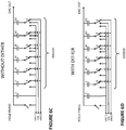
- each Figure shows 6 capacitors with respective weights C, 2C, 4C, 8C, 16C, and 32C within a switched capacitor sampling DAC 320.
- the top plates of the array of capacitors are further connected to a terminating capacitor 330 by way of a shared conductor 322.
- only the three most significant capacitors 8C, 16C and 32C can be connected to sample the input signal VIN during a sampling phase by connecting their lower plates (as shown) to VIN via respective switches.
- the capacitors C, 2C, and 4C are connected to VREF2 (e.g., ground) during the sampling phase.
- VREF2 e.g., ground
- the lower three capacitors are connected to either VREF1 or VREF2 (e.g., ground or 0V) in accordance with a dither code.
- the dither code is "101" (or "101000" for the entire array reading from least significant to most significant bit) resulting in the capacitors C and 4C being connected to VREF1 and the capacitor 2C being connected to VREF2.
- Sampling switch 350 when closed, connects a reference voltage (e.g., VREF1 or VREF2) to the shared conductor 322.
- a reference voltage e.g., VREF1 or VREF2
- Sampling switch 350 is opened to hold the sampled input value as per Figure 6A , or the combination of the sampled input signal and the dither as per Figure 6B .
- the sampling DAC can be set to a hold state, which is shown in Figure 6C for the case without a dither, and Figure 6D for the case with a dither. It can be seen that the hold states are the same, with all the capacitors being connected to VREF2 (e.g., ground).
- VREF2 e.g., ground
- the digital word representing the conversion result here "011101” is applied to the sampling DAC 220 so that it can form a residue.
- the DAC 220 is set to "011101", i.e., the capacitors 2C, 4C, 8C, and 32C are connected to VREF1, whereas the other capacitors are connected to VREF2.
- the dither value of 101000 is added to the converted value "011101” to form "110011” which is used to set the switch positions of the capacitors of the sampling DAC.
- the length of the sampling DAC is not restricted to six capacitors (assuming one capacitor per bit), and this number was chosen as a simple example, sampling DACs may have more or fewer "bits" of the designers will.
- FIG. 7 Such an arrangement is shown in Figure 7 .
- the ADC part 200 has been fabricated using a DAC slice 210.1, and the sampling DAC 220 is formed from a plurality of sampling DAC slices 210.2 to 210.n.
- all the slices are the same.
- each has the same sampling response, in terms of input impedance, acquire time or time constant and the same transition time to transition from sample to hold states.
- This means the signal in the slices 220.2 to 220.n of the residue forming DAC 220 are the same as the signal in the slice 201.1 of the ADC.
- this statement might seem so obvious that it seems superfluous, but in fact, it highlights an important and easily overlooked condition that should be observed to achieve good performance from the sliced architecture of Figure 7 . This will be discussed later.
- the dither generator 400 generates one or more random digital words at a time which are supplied to one or more of the DAC slices 210.2 to 210.n within the residue DAC 220.
- the dither is preferably applied by setting some of least significant capacitors within the sampling DAC slices to provide a dither value before or during the sampling process such that the analog value on the input signal sampled onto the respective sampling DAC arrays within the slices is effectively modified by the value of the respective dither.
- the dither could also be applied after sampling and added to the digital word provided to each of the DAC slices when forming the residue where the residue amplifier has sufficient dynamic range to pass the sum of the residue and the dither to a following stage.
- Table 1 shows the evolution of voltage from 0 to an arbitrary value of '1' expressed as a function of time constants Tc of a first RC combination as exemplified by a first sample and hold circuit and the voltage on a second sample and hold circuit where its time constant Tc' differs from Tc by being 10% larger.
- the sample circuit samples for at least 12 time constants; for 18 bit conversion the sampling circuit samples for at least 14 time constants, and for 20 bit conversion the sampling circuit samples for 15 time constants.
- the performance of the transistor switches in terms of the on state resistance R ON is limited by the fabrication process. It is possible to put transistors in parallel or make a wider transistor to reduce R ON , but this comes at a cost of increased charge injection from the gate of the transistor to the sampling capacitor, which can be viewed as a feature of the gate to channel parasitic capacitance of the transistor. Consequently making the transistor switches wider to reduce R ON compared to the value of the capacitor connected to the switch is not an automatic win as the charge injection problem worsens and degrades the accuracy of the analog to digital converter.
- later embodiments of this disclosure allow the on resistance to be increased, and deliberately so, while still maintaining good speed and noise performance.
- N RMS K B T C
- K B is the Boltzmann's constant.
- T Temperature in Kelvin.
- C is capacitance in Farads.
- N RMS The root mean square (RMS) thermal noise, on a capacitor at 300K is set out below for a range of capacitor sizes.
- Vinpp represents the peak-to-peak value of the input signal.
- ENOB SNR ⁇ 1.76 60.2
- an ADC is to sample an input with a full scale range of 5V with 18 bit resolution.
- the sampling noise needs to be further reduced to around 11 ⁇ V RMS .
- the speed of the sampling stage is not the only factor that needs to be taken into consideration as the samples cannot be taken back-to-back as the ADC needs some time to make its conversion.
- Both the ringing and the capacitor to capacitor charge redistribution limit the conversion rate.
- the ringing needs to be given time to subside below an appropriate value, such as 1 LSB (or the amount of error that redundancy within the ADC can reasonably be expected to correct), and the charge redistribution also needs to be asymptote to an appropriate value.
- an appropriate value such as 1 LSB (or the amount of error that redundancy within the ADC can reasonably be expected to correct)
- the charge redistribution also needs to be asymptote to an appropriate value.
- it is not required to wait 14 to 16 time constants after setting the bits in a bit trial before strobing the comparator to look at the result of the bit trial. In practice it is reasonable to wait for a much shorter time, say around 4 time constants in a converter having redundancy.
- Pipelining allows the bit trials to be split between different stages of an ADC and while the conversion time between taking a sample and outputting a result is not improved by pipelining the throughput or conversion rate is nearly doubled in a two stage pipeline.
- the other benefit of pipelining is the ability to provide amplification of the signal as it is passes to a subsequent stage of the pipeline, thus the comparators of the subsequent stage can make faster decisions.
- the slices can be made with relatively small values of capacitance such that slice 210.1 can be used to perform an ADC conversion and arrive at an interim result relatively quickly but with a noise penalty.
- the interim result can be used by one or more other slices 210.2 to 210.n to form a residue.
- the one or more other slices may have bigger values of C, or work in parallel to synthesize a bigger value of C such that the residue has an improved thermal noise figure.
- the stages should be "matched” to set their RC time constant to within an acceptable value.
- the limit of what constitutes “acceptable” depends on a time budget for sampling the input signal and also for allowing charge redistribution and ringing to settle to around 1 LSB of the channel or slice.
- DC Direct Current
- AC Alternating Current
- each slice includes a sampling DAC, and the sampling stages are matched so as to have capacitors and transistors at a given electrical position in one slice being substantially the same as the equivalent capacitors and transistors in others of the slices.
- a unit cell comprising a unit size capacitor C in association with unit sized transistors for connecting one of the plates of the capacitor to VIN, VREF1 and VREF2 respectively is used repeatedly to form the slices.
- Each unit cell is nominally identical to each other unit cell in its electrical performance.
- the cells can be grouped together, either permanently on or as part of a dynamic allocation of cells to groups. Two cells can be grouped together to form a capacitance of 2C, four cells can be grouped together to form a capacitance of 4C and so on. If desired, cells do not need to be grouped together to from groups in a binary sequence of weights. Cells could be grouped to form capacitors to provide redundancy.
- Cells can also be connected in series to form effective capacitances of C/2, C/3, C/4 and so on. It can be convenient to work predominantly with cells of 2C as a way of reducing the switch control and driver requirements, and only to have one or a few cells of 1C being individually controllable.
- a first stage of a pipeline converter resolves the 6 MSB of the signal to be digitized.
- the input signal VIN is sampled onto two sampling DACs.
- One sampling DAC called “Big DAC” has three times the capacitance of the other sampling DAC, called “Small DAC”.
- the small DAC is used to perform the SAR trials, so as to save power, but once it has finished then both DACs are connected to a common node such that their residues are merged together in order to meet the 13 bit noise requirement.
- the example does not consider or have any teaching of scaling the transistor switches to match the sampling time constants of the DACs or of co-locating the sampling switches to minimize timing skews.
- a RC sampling circuit is designed to have a -3dB bandwidth of 10MHz.
- C is chosen to be 40pF in order to meet the noise performance figure required to achieve 18 bits of resolution.
- f 1 2 ⁇ RC
- the resistors may have values between ohms and several hundred ohms. In an embodiment resistors of around 160 ⁇ were used.
- the transistors may have on resistances of only a few ohm, and transistor to transistor on resistance variation may only be fractions of an Ohm. This approach significantly improves matching between the sampling DAC slices.
- some or all of the remaining DAC slices 210.2 to 210.n are configured to sample the input VIN simultaneously with slice 210.1 and to act together to form a residue DAC 220 to form an analog output voltage Vresidue representing the difference between VIN and Vdac, where Vdac is the voltage produced by the residue DAC 220 when driven with the "result" of the analog to digital conversion formed by the first DAC slice 210.1 when driven by the SAR logic 214 to arrive at a P bit conversion, where P is the effective resolution in bits of the slice 210.1.
- the first DAC slice 210.1 may be formed from a non-subdivided switched capacitor array, a segmented or sub-divided switched capacitor array or a sampling capacitor and associated DAC.
- each of the slices 210.1 to 210.n is coupled to VIN and used to sample VIN.
- the sampling switches 350 (see Figure 6A ) of the slices are co-located to ensure that they receive their "hold” instruction at the same time and also to ensure that each switch 350 suffers the same process, voltage, and temperature (PVT) variation as each other switch.
- PVT process, voltage, and temperature
- This helps ensure that each sampling DAC circuit has the same electrical performance as each other sampling DAC, for example matched RC time constants, and the switches 350 transition between conducting and non-conducting at the same slew rate and at the same time, thereby avoiding phase shifts between the DAC slices 210.1 to 210.n when operating concurrently to acquire (for example sample and hold) a shared input signal.
- the first DAC slice 210.1 can be used to form a SAR conversion of the sampled signal.
- a conversion may include use of a further sub-ADC, for example in the form of a Flash ADC to provide a near instantaneous conversion of the first two or three bits of the P bit conversion performed by the DAC slice 210.1.
- SAR conversions can also include the inclusion of additional bits to provide redundancy in the result and that the conversion can also be performed with radix ⁇ 2 technology and that multiple bits can be determined in a single bit trail period, for example by using a three level quantizer in place of the comparator.
- the status of the most significant bits of the P bit output word become known before the status of the least significant bits of the P bit output word.
- This allows the output from the SAR logic 214 to be provided to the slices 210.2 to 210.n in the residue DAC 220 in order to set the bits in those DAC slices on a bit by bit basis thereby allowing the voltage transitions caused by switching the capacitors in each slice into an appropriate configuration, and the ringing that this may introduce, has time to die away before the output from the residue DAC 220 is gained up by the residue amplifier 230.
- the setting of the bits in the slices 210.2 to 210.n within the residue DAC 220 can be staggered in time such that the transitions do not happen in unison.
- the magnitude of the initial transitions for example relating to the most significant bit and the next most significant bit can be reduced by initially setting half of the slices 210.2 to 210.n with their most significant bits set and the other half of the slices with their most significant bit unset. Consequently, as a result of the first bit trial statistically only half of the DAC slices are likely to have to be transitioned.
- the same technique can be used with the next most significant bit and so on.
- An alternative approach may be based on the fact that, in use, the input signal may be oversampled compared to its Nyquist frequency limit and hence statistically the first few bits of the input word are unlikely to have changed between one sample and an immediately following one.
- each DAC slice 210.1 to 210.n to have a smaller capacitance therein, which reduces the RC time constant of each DAC slice, and consequently a conversion could be performed more quickly.
- the thermal noise associated with a capacitor at 300 K was tabulated. This was used to show that, in a worked example where a dynamic range of 5 V was to be converted with 18 bit resolution, then the minimum capacitance of the DAC needed to be at least ⁇ 40 pF. However, if all of the DAC slices where formed such that they each had an effective capacitance of 4 pF then connecting the DAC slices 210.2 to 210.n to form a residue DAC places their capacitances in parallel.
- the sampling DACs can be formed from repeated unit cells.
- One such unit cell 270 having a value 1C is shown in Figure 8 .
- the unit cell comprises a capacitor 272 having a value of 1C.
- One of its plates, the uppermost plate in Figure 8 is connected to the shared conductor 322 ( Figure 6A ).
- the bottom plate of the capacitor is connected by a three-way switch formed of transistors 274, 276 and 278 to allow the bottom plate to be isolated, connected to VIN, VREF1 (typically from a precision voltage reference) or VREF2 (typically 0V).
- Each of the transistors is controlled by a switch controller 279, such as SAR logic 214 from Figure 7 .
- the transistor 274 connecting the capacitor to the input node VIN may be in series with a resistor 280 so as to more accurately define the "on" resistance presented by the unit cell when it is sampling the input signal at VIN.
- the transistor 274 may (or may not) have its gate control signal modified by a bootstrap circuit 282 so as to hold a gate to source voltage Vgs of the transistor 274 constant with respect to VIN.
- the unit cell 270 may be placed in parallel with other unit cells to form properly scaled combinations of switch and capacitor, as represented by unit cells 270a and 270b being placed in parallel to form a 2C weight, and so on.
- unit cells 270 are required.
- the unit cells can be very well matched within an integrated circuit. This means that the unit cells may be permanently assigned to groups of 1, 2, 4, 8, and 16 if desired, or alternatively the groupings may be dynamically formed on the fly by the switch controller at each sampling event to randomize any mismatch errors.
- the cells may be operated in a unary encoding style and the cells participating in such an encoding scheme of the output may be selected dynamically (on the fly).
- Figure 9 shows a variation of Figure 7 where a sub-DAC 285, such as a 3 bit Flash converter, is used to set the three most significant bits of the SAR converter more quickly. Less than or more than 3 bits may be converted by the sub-DAC 285.
- a sub-DAC 285 such as a 3 bit Flash converter
- the voltage residue formed by the sampling DAC 220 may then be gained up by a residue amplifier 230 before being provided to a further analog to digital converter 240. It should also be noted, as shown in Figure 10 , that the residue amplifier 230 need not necessarily be provided.
- FIG 11 schematically shows the circuit arrangement of Figure 7 in greater detail.
- each of the slices 210.1 to 210.n are identical, and each comprise a segmented capacitor array forming a sampling DAC 402 together with a sub-DAC 404.
- the sampling DACs are identical.
- the sub-DACs are also identical. However this need not be the case.
- the sub-DACs could be formed with lower resolution if desired.
- the sub-DACs of the slices 210.2 to 210.n can be shortened or omitted if desired.
- the residue DAC can be driven to apply sub-LSB dither to its output signal for supply to the next stage in the pipelined analog to digital converter.
- a data manipulation block 250 is provided between the SAR logic 214 and each of the slices 210.2 to 210.n in the residue DAC 220.
- the data manipulation block allows the digital word to each of the DAC slices 210.2 to 210.n to be individually set.
- deliberately selecting different words provides for enhanced resolution or the incorporation of dither.
- FIG 12 is a generic representation of Figure 11 where each slice 210.1 to 210.n is divided into a sampling DAC portion 210.1a, 210.2a and so on up to 210.na and a sub-DAC 210.1b, 210.2b, 210.3b and so on.
- the sampling DACs 210.2a to 210.na are identical to each other.
- the sampling DAC 210.1a may or may not be the same as the sampling DACs 210.2a to 210.na, but advantageously has very similar electrical properties, and this is best achieved by forming it of the same unit cell construction as the other slices.
- the sub-DACs need not be the same.
- the sub-DAC 210.1b may be formed, for example, with more bits than the other sub-DACs.
- the current flow between the capacitors along the bond wires can perturb the voltage reference.
- the arrangement described herein has the advantage of reducing the perturbation of the voltage reference during the bit trial sequence and also gives the potential for the DAC slices 210.2 to 210.n in the residue DAC to be provided with a buffered version of the reference voltages which may be provided by way of a further buffer such that the reference voltage provided to the first slice 210.1 does not suffer perturbation due to switching of the capacitors in the slices 210.2 to 210.n to set up the residue DAC. It can be seen that if the capacitance of the capacitor array is effectively reduced from 40 pF to 4 pF then the current drawn from the reference is correspondingly reduced. Thus the energy required for conversion is reduced.
- each slice would have a capacitance of 5pF.
- This 5pF is split up between, say, 31 unit cells in a 5 bit example or 63 unit cells in a 6 bit example of a sampling DAC array.
- Figure 13 shows an arrangement where at least some, and preferably each, of the slices 210.2 to 210.n of the residue DAC is connected to the external reference by way of a respective buffer 420.2 to 420.n which is selectively disconnectable from the slice 210.2 to 210.n by a series switch 422.2 to 422.n and where the slice 201.2 to 210.n can also be directly connected to the external reference by way of a further switch 424.2 to 424.n. Consequently, the residue DAC slices 210.2 to 210.n can each be charged by way of the buffer for the majority of the set up time thereby reducing the current drawn from the external reference, and be connected to the external reference towards the end of the settling time such that they settle towards a correct voltage unaffected by offsets within their respective buffers. Furthermore each of the switched capacitor arrays can have their bandwidths limited by selected connection to a bandwidth limiting resistor 430 by way of respective switches 440.1 to 440.n.
- Figure 14 schematically illustrates one embodiment of the present disclosure where a mini ADC 450, formed from one of the slices, works in association with eight other slices which form the residue DAC to drive the residue amplifier 230.
- the residue amplifier is connected to a further ADC 240.
- the first ADC in this example, provides 6 or more bits of resolution while the second ADC 152 provides the remaining number of bits, for example 8 or more 9 bits of resolution to reach the desired overall resolution of the ADC.
- each slice may present a capacitance of 3.2 pF, but the total digital to analog converter presented for the purposes of thermal noise amounts to 25.6 pF with the DACs operating in parallel.
- the time to complete an SAR conversion can be expected to be longer than the time required to set up the individual DAC slices within the residue DAC.
- the output from the residue DAC is only really required after the SAR conversion from the first ADC is completed.
- the SAR slices can be operated in a ping-pong manner such that one of them is about half way through its conversion when the other is sampling. Under such an arrangement the residue DAC has to sample at the same time as each of the SAR slices but immediately after it has finished sampling it can already be preset with at least half of the output word.
- a sub-ADC such as a Flash ADC in order to get the first few bits of the bit trial performed rapidly or to reduce the signal swing during trials.
- Figure 15 schematically illustrates an alternative embodiment of a pipelined architecture where two fast ADCs 460 and 462 are provided within ADC1 200, and each of the fast ADCs is associated with eight DAC slices.
- the first ADC 200 is operated in a time interleaved manner and hence exceptionally minor mismatches might still result in the generation of additional sampling tones.
- one or more slices can be shuffled amongst the slices of each one of the residue DACs in order to reduce the risk of tones.
- FIG 16 schematically shows a timing diagram for the arrangement in Figure 15 .
- each of the first ADCs designated “A” and “B” in Figures 15 and 16 operates out of phase with the other such that when ADC "A” 460 is performing its acquisition in a time period T A between successive "convert start” signals, the ADC “B” 462 undertakes its bit trials and then passes its result to the residue amplifier.
- the residue amplifier extends approximately half of its time (denoted RA_A or RA_B) amplifying the residue from one of the residue DACs associated with the respective slice ADCs "A" and “B", and the other half of its time undergoing auto-zeroing, AZ, in order to remove offset errors therefrom.
- RA_A or RA_B the residue amplifier extends approximately half of its time (denoted RA_A or RA_B) amplifying the residue from one of the residue DACs associated with the respective slice ADCs "A” and “B”, and the other half of its time undergoing auto
- the number of stages in the pipeline can vary between two and the resolution of the converter. Put another way, each stage in the pipeline could be arranged to convert only one bit.
- the teachings of this disclosure would still be applicable to such a deeply pipelined arrangement as the time constant of each stage would be reduced by the multiple slices of a given stage which will act in parallel to provide the required noise performance.
- the present disclosure is highly flexible and can be used in a vast number of configurations where DACs are required to interact with capacitor based sampling circuits.
- the interleaving ratio can be 2x or more.
- FIG 17 schematically illustrates an embodiment of a layout floorplan of the circuit shown in Figure 15 .
- the DAC slices are arranged in parallel between the comparator, "comp”, associated with the slice ADC (sADCa and sADCb), and the residue amplifier (RA), associated with this stage.
- One of the slices within each bank of switched capacitor DACs has, in this example, been allocated the role of being the slice ADC (sADC).
- Figure 19 builds on the teachings of Figure 5 , and the same reference numbers are used for like parts.
- the dither generator 400 generates a first dither value, which is represented as bits D A to D 1 , where A represents an arbitrary number.
- the dither can represent an integer part and a fractional part (referred to the LSB of the stage).
- the first dither word comprises bits D 6 , D 5 , D 4 , D 3 , D 2 , and D 1 .
- D 6 , D 5 , and D 4 represent an integer part and D 3 , D 2 , and D 1 represent a fractional part.
- Seven slices are operating together to form the sampling DAC.
- the fractional part represented by D 3 , D 2 , and D 1 can be set by the ratio in which the slices are set to integer values. For example, if the integer portion of the dither word is 2 and the fractional part is "101" or 5/7 then two of the slices would be set to "2" and five of the slices would be set to "3" when sampling the input word.
- D 6 to D 1 namely the first dither value is used to dither the value sampled on to the sampling DAC 220.
- a selection of bits of the first dither value can be used to form a second dither value.
- Bits not selected to form the second dither value can be used to form a third dither value.
- bits D 5 , D 3 , D 2 , and D 1 are used to form the second dither value which is used to dither the ADC part 200 of the stage.
- the dither comprises a fractional part of 1/7, 2/7, 3/7, 4/7, 5/7, or 6/7 plus an integer part which is either 0 or 2.
- the third dither value comprises part of the first dither value, namely D 4 which represents either 1 or zero and D 6 which represents 4 or zero.
- D 4 which represents either 1 or zero
- D 6 which represents 4 or zero.
- D 5 , D 3 , D 2 , and D 1 This leaves some residual dither, D 5 , D 3 , D 2 , and D 1 , which manifests itself as an analog dither at the output of the sampling DAC 220 when it forms the analog residue signal.
- the digital value D 5 , D 3 , D 2 , and D 1 is passed to a subsequent stage such that it can be subtracted from the digital value formed by the subsequent stage.
- no dither correction is applied to the digital word output from the first ADC part 200 in the first stage, i.e., summer/subtractor 224 is omitted, and all of the dither value is passed to a subsequent stage comprising a second ADC 240 which converts the residue and dither output by the sampling DAC 220, and the digital value of the dither is removed from the output of the second ADC 240 by a subtractor 241.
- summer 222 maybe omitted such that the sampling DAC does not sample the dither, or equivalently the first dither value is not supplied to the sampling DAC 220 to dither the analog input signal that it samples.
- ADC1 and ADC2 are concentrated so that the ADC1 provides a word representing the most significant bits of the conversion result and ADC2 outputs a word representing the least significant bits of the conversion result. This is also the case for the earlier examples disclosed herein.
- the present disclosure encompasses apparatuses which can perform the various methods described herein.
- Such apparatuses can include circuitry illustrated by the Figures and described herein.
- Parts of various apparatuses can include electronic circuitry to perform the functions described herein.
- the circuitry can operate in analog domain, digital domain, or in a mixed-signal domain.
- one or more parts of the apparatus can be provided by a processor specially configured for carrying out the functions described herein (e.g., control-related functions, timing-related functions).
- processor can be an on-chip processor with the ADC.
- the processor may include one or more application specific components, or may include programmable logic gates which are configured to carry out the functions describe herein.
- the processor may be configured to carrying out the functions described herein by executing one or more instructions stored on one or more non-transitory computer media.
- references to various features e.g., elements, structures, modules, components, steps, operations, characteristics, etc.
- references to various features e.g., elements, structures, modules, components, steps, operations, characteristics, etc.
- references to various features included in “one embodiment”, “example embodiment”, “an embodiment”, “another embodiment”, “some embodiments”, “various embodiments”, “other embodiments”, “alternative embodiment”, and the like are intended to mean that any such features are included in one or more embodiments of the present disclosure, but may or may not necessarily be combined in the same embodiments.
- the functions described herein illustrate only some of the possible functions that may be executed by, or within, systems/circuits illustrated in the Figures. Some of these operations may be deleted or removed where appropriate, or these operations may be modified or changed considerably without departing from the scope of the present disclosure.
Landscapes
- Engineering & Computer Science (AREA)
- Theoretical Computer Science (AREA)
- Signal Processing (AREA)
- Power Engineering (AREA)
- Analogue/Digital Conversion (AREA)
Applications Claiming Priority (2)
| Application Number | Priority Date | Filing Date | Title |
|---|---|---|---|
| US15/916,009 US10516408B2 (en) | 2018-03-08 | 2018-03-08 | Analog to digital converter stage |
| US16/052,890 US10505561B2 (en) | 2018-03-08 | 2018-08-02 | Method of applying a dither, and analog to digital converter operating in accordance with the method |
Publications (2)
| Publication Number | Publication Date |
|---|---|
| EP3537609A1 true EP3537609A1 (de) | 2019-09-11 |
| EP3537609B1 EP3537609B1 (de) | 2022-07-27 |
Family
ID=65729206
Family Applications (1)
| Application Number | Title | Priority Date | Filing Date |
|---|---|---|---|
| EP19161602.8A Active EP3537609B1 (de) | 2018-03-08 | 2019-03-08 | Verfahren zum anwenden von überlagerter schwingung und analog-digital-wandler gemäss dem verfahren |
Country Status (4)
| Country | Link |
|---|---|
| US (1) | US10505561B2 (de) |
| EP (1) | EP3537609B1 (de) |
| JP (1) | JP6782804B2 (de) |
| CN (1) | CN110247659B (de) |
Families Citing this family (7)
| Publication number | Priority date | Publication date | Assignee | Title |
|---|---|---|---|---|
| US10516408B2 (en) | 2018-03-08 | 2019-12-24 | Analog Devices Global Unlimited Company | Analog to digital converter stage |
| KR102661956B1 (ko) * | 2019-02-27 | 2024-04-29 | 삼성전자주식회사 | 아날로그 디지털 변환기 |
| US10965302B1 (en) * | 2019-10-12 | 2021-03-30 | Analog Devices International Unlimited Company | Background static error measurement and timing skew error measurement for RF DAC |
| US11075643B2 (en) | 2019-12-20 | 2021-07-27 | Analog Devices International Unlimited Company | Background timing skew error measurement for RF DAC |
| US10742225B1 (en) * | 2019-12-27 | 2020-08-11 | Intel Corporation | n-bit successive approximation register analog-to-digital converter and method for calibrating the same, receiver, base station and mobile device |
| US11128310B1 (en) | 2020-04-24 | 2021-09-21 | Analog Devices International Unlimited Company | Background duty cycle error measurement for RF DAC |
| CN117571163B (zh) * | 2024-01-11 | 2024-04-02 | 赛卓电子科技(上海)股份有限公司 | 一种消除传感器输出抖动的方法、装置及传感器 |
Citations (3)
| Publication number | Priority date | Publication date | Assignee | Title |
|---|---|---|---|---|
| US20060114144A1 (en) * | 2004-09-10 | 2006-06-01 | Lyden Colin G | INL curve correction in a pipeline ADC |
| US20130120174A1 (en) * | 2011-11-14 | 2013-05-16 | Analog Devices, Inc. | Correlation-based background calibration for reducing inter-stage gain error and non-linearity in pipelined analog-to-digital converters |
| US9331709B2 (en) * | 2012-04-20 | 2016-05-03 | Linear Technology Corporation | Analog-to-digital converter |
Family Cites Families (43)
| Publication number | Priority date | Publication date | Assignee | Title |
|---|---|---|---|---|
| US4499594A (en) | 1982-06-10 | 1985-02-12 | The Aerospace Corporation | Digital to analog converter |
| US4546343A (en) | 1984-07-03 | 1985-10-08 | The United States Of America As Represented By The Secretary Of The Air Force | Data acquisition channel apparatus |
| US5041831A (en) | 1988-04-26 | 1991-08-20 | Hewlett-Packard Company | Indirect D/A converter |
| US5493298A (en) * | 1993-03-01 | 1996-02-20 | Hewlett-Packard Company | Dithered analog-to-digital converter |
| US5600322A (en) | 1994-04-29 | 1997-02-04 | Analog Devices, Inc. | Low-voltage CMOS analog-to-digital converter |
| US5621409A (en) | 1995-02-15 | 1997-04-15 | Analog Devices, Inc. | Analog-to-digital conversion with multiple charge balance conversions |
| US6172629B1 (en) * | 1998-02-19 | 2001-01-09 | Lucent Technologies Inc. | Multistage analog-to-digital converter employing dither |
| DE19807856A1 (de) | 1998-02-25 | 1999-08-26 | Philips Patentverwaltung | Schaltungsanordnung mit Strom-Digital-Analog-Konvertern |
| WO2000044098A1 (en) * | 1999-01-19 | 2000-07-27 | Steensgaard Madsen Jesper | Residue-compensating a / d converter |
| AU2001243296A1 (en) * | 2000-02-22 | 2001-09-17 | The Regents Of The University Of California | Digital cancellation of d/a converter noise in pipelined a/d converters |
| US6657570B1 (en) | 2000-06-22 | 2003-12-02 | Adc Telecommunications, Inc. | Automatic level control for input to analog to digital converter |
| US6404364B1 (en) * | 2000-08-24 | 2002-06-11 | Agere Systems Guardian Corp. | Multistage converter employing digital dither |
| US6507304B1 (en) | 2002-05-02 | 2003-01-14 | National Semiconductor Corporation | Current steering segmented DAC system |
| US6828927B1 (en) | 2002-11-22 | 2004-12-07 | Analog Devices, Inc. | Successive approximation analog-to-digital converter with pre-loaded SAR registers |
| US6784814B1 (en) * | 2003-03-07 | 2004-08-31 | Regents Of The University Of Minnesota | Correction for pipelined analog to digital (A/D) converter |
| DE10344354B4 (de) | 2003-09-24 | 2006-11-02 | Infineon Technologies Ag | Analog-Digital-Wandler und Verfahren zum Betreiben eines Analog-Digital-Wandlers |
| US6970120B1 (en) * | 2004-06-12 | 2005-11-29 | Nordic Semiconductor Asa | Method and apparatus for start-up of analog-to-digital converters |
| US20060022854A1 (en) * | 2004-07-29 | 2006-02-02 | Johnny Bjornsen | Method and apparatus for operating correlator of an ADC circuit |
| US7015853B1 (en) | 2005-03-09 | 2006-03-21 | Cirrus Logic, Inc. | Data converter with reduced differential nonlinearity |
| US7286075B2 (en) * | 2005-11-14 | 2007-10-23 | Analog Devices, Inc. | Analog to digital converter with dither |
| US7158070B1 (en) | 2005-12-21 | 2007-01-02 | Elan Microelectronics Corporation | Analog-to-digital converter capable of performing self-test |
| DE102006046966A1 (de) * | 2006-05-26 | 2007-11-29 | Rohde & Schwarz Gmbh & Co. Kg | Messvorrichtung und Messverfahren zum Messen der Leistung eines Hochfrequenzsignals |
| US7663518B2 (en) | 2006-10-10 | 2010-02-16 | Analog Devices, Inc. | Dither technique for improving dynamic non-linearity in an analog to digital converter, and an analog to digital converter having improved dynamic non-linearity |
| US7710300B2 (en) | 2008-04-03 | 2010-05-04 | Broadcom Corporation | Segmented data shuffler apparatus for a digital to analog converter (DAC) |
| US7944378B1 (en) | 2008-08-18 | 2011-05-17 | Marvell International Ltd. | Circuits and methods for calibrating analog and digital circuits |
| JP4862031B2 (ja) | 2008-10-20 | 2012-01-25 | 株式会社ニューフレアテクノロジー | マスク欠陥レビュー方法及びマスク欠陥レビュー装置 |
| US7944386B2 (en) | 2008-10-21 | 2011-05-17 | Analog Devices, Inc. | Apparatus for and method of performing an analog to digital conversion |
| US7602324B1 (en) * | 2009-01-20 | 2009-10-13 | Himax Media Solutions, Inc. | A/D converter and method for converting analog signals into digital signals |
| US7830287B1 (en) * | 2009-05-08 | 2010-11-09 | Himax Media Solutions, Inc. | Analog to digital converter having digital correction logic that utilizes a dither signal to correct a digital code |
| US7924203B2 (en) | 2009-06-12 | 2011-04-12 | Analog Devices, Inc. | Most significant bits analog to digital converter, and an analog to digital converter including a most significant bits analog to digital converter |
| US8451160B1 (en) | 2010-05-17 | 2013-05-28 | Marvell International Ltd. | Low power high speed pipeline ADC |
| US8319673B2 (en) * | 2010-05-18 | 2012-11-27 | Linear Technology Corporation | A/D converter with compressed full-scale range |
| US8203472B2 (en) * | 2010-09-20 | 2012-06-19 | Raytheon Company | Compensation of clock jitter in analog-digital converter applications |
| US8618975B2 (en) | 2011-10-26 | 2013-12-31 | Semtech Corporation | Multi-bit successive approximation ADC |
| US8552897B1 (en) | 2012-03-22 | 2013-10-08 | Analog Devices, Inc. | Reference circuit suitable for use with an analog to digital converter and an analog to digital converter including such a reference circuit |
| US8766839B2 (en) | 2012-09-07 | 2014-07-01 | Texas Instruments Incorporated | Reducing the effect of elements mismatch in a SAR ADC |
| US8730073B1 (en) | 2012-12-18 | 2014-05-20 | Broadcom Corporation | Pipelined analog-to-digital converter with dedicated clock cycle for quantization |
| EP2993787B1 (de) | 2014-09-05 | 2020-07-15 | Dialog Semiconductor (UK) Ltd | Verallgemeinertes datengewichtetes Mittelwertbildungsverfahren für gleichmäßig gewichtete Mehrbit-D/A-Elemente |
| US9413381B2 (en) | 2014-12-17 | 2016-08-09 | Broadcom Corporation | High-speed, low-power reconfigurable voltage-mode DAC-driver |
| US9748966B2 (en) * | 2015-08-06 | 2017-08-29 | Texas Instruments Incorporated | Histogram based error estimation and correction |
| CN105811984B (zh) | 2016-03-11 | 2020-06-02 | 清华大学 | 输入采样与转换电路 |
| US9735799B1 (en) | 2016-07-29 | 2017-08-15 | Analog Devices, Inc. | Envelope-dependent noise-shaped segmentation in oversampling digital-to-analog converters |
| US9825643B1 (en) | 2016-10-31 | 2017-11-21 | Rohde & Schwarz Gmbh & Co. Kg | Digital to analog conversion device and calibration method |
-
2018
- 2018-08-02 US US16/052,890 patent/US10505561B2/en active Active
-
2019
- 2019-03-08 CN CN201910174092.8A patent/CN110247659B/zh active Active
- 2019-03-08 EP EP19161602.8A patent/EP3537609B1/de active Active
- 2019-03-08 JP JP2019042546A patent/JP6782804B2/ja active Active
Patent Citations (3)
| Publication number | Priority date | Publication date | Assignee | Title |
|---|---|---|---|---|
| US20060114144A1 (en) * | 2004-09-10 | 2006-06-01 | Lyden Colin G | INL curve correction in a pipeline ADC |
| US20130120174A1 (en) * | 2011-11-14 | 2013-05-16 | Analog Devices, Inc. | Correlation-based background calibration for reducing inter-stage gain error and non-linearity in pipelined analog-to-digital converters |
| US9331709B2 (en) * | 2012-04-20 | 2016-05-03 | Linear Technology Corporation | Analog-to-digital converter |
Non-Patent Citations (1)
| Title |
|---|
| WANG KE, FAN CHAOJIE, PAN WENJIE, AND ZHOU JIANJUNA: "A 14-bit 100MS/s SHA-less pipelined ADC with 89dB SFDR and 74.5dB SNR", IEICE ELECTRONICS EXPRESS, vol. 12, no. 5, 10 February 2015 (2015-02-10), pages 1 - 11, XP055609942, DOI: 10.1587/elex.12.20150070 * |
Also Published As
| Publication number | Publication date |
|---|---|
| JP2019161649A (ja) | 2019-09-19 |
| US20190280706A1 (en) | 2019-09-12 |
| US10505561B2 (en) | 2019-12-10 |
| EP3537609B1 (de) | 2022-07-27 |
| CN110247659A (zh) | 2019-09-17 |
| CN110247659B (zh) | 2023-06-20 |
| JP6782804B2 (ja) | 2020-11-11 |
Similar Documents
| Publication | Publication Date | Title |
|---|---|---|
| EP3537609B1 (de) | Verfahren zum anwenden von überlagerter schwingung und analog-digital-wandler gemäss dem verfahren | |
| EP3537608B1 (de) | Verfahren zur linearisierung der übertragungscharakteristik durch dynamische elementanpassung | |
| US11082056B2 (en) | Analog to digital converter stage | |
| US8587464B2 (en) | Off-line gain calibration in a time-interleaved analog-to-digital converter | |
| US8310388B2 (en) | Subrange analog-to-digital converter and method thereof | |
| JP4875099B2 (ja) | ディザを有するアナログ・ディジタル変換器 | |
| TWI467924B (zh) | 連續近似暫存器類比對數位轉換器及其轉換方法 | |
| KR101512098B1 (ko) | 커패시터-저항 하이브리드 dac를 이용한 sar adc | |
| US9912341B2 (en) | Data conversion with redundant split-capacitor arrangement | |
| KR102289432B1 (ko) | 연속적인 근사 레지스터 아날로그 디지털 변환 장치 | |
| USRE45798E1 (en) | Systems and methods for randomizing component mismatch in an ADC | |
| US10601433B2 (en) | Analogue to digital converter | |
| KR20160058140A (ko) | 파이프라인식 연속 아날로그-투-디지털 변환기 | |
| EP2403144A1 (de) | Digitales Hintergrundkalibrierungssystem und -verfahren zur Analog-Digital-Wandlung nach dem Verfahren der schrittweise Annäherung (SAR) | |
| Nam et al. | An embedded passive gain technique for asynchronous SAR ADC achieving 10.2 ENOB 1.36-mW at 95-MS/s in 65 nm CMOS | |
| KR101711542B1 (ko) | 레인지-스케일링 기반의 복합 파이프라인 아날로그-디지털 컨버터 | |
| US10707889B1 (en) | Interleaving method for analog to digital converters | |
| KR101927101B1 (ko) | 축차 비교형 아날로그-디지털 변환기 및 이를 포함하는 cmos 이미지 센서 | |
| KR102199016B1 (ko) | 샘플앤홀드 공유에 기반하는 2단 플래시 adc | |
| US20240097698A1 (en) | Successive approximation register (sar) analog-to-digital converter (adc) with input-dependent least significant bit (lsb) size | |
| Zeloufi et al. | Design of low power and low area 12-bit 40MSPS SAR ADCs with a redundancy algorithm and digital calibration for high dynamic range calorimeter readout |
Legal Events
| Date | Code | Title | Description |
|---|---|---|---|
| PUAI | Public reference made under article 153(3) epc to a published international application that has entered the european phase |
Free format text: ORIGINAL CODE: 0009012 |
|
| STAA | Information on the status of an ep patent application or granted ep patent |
Free format text: STATUS: THE APPLICATION HAS BEEN PUBLISHED |
|
| AK | Designated contracting states |
Kind code of ref document: A1 Designated state(s): AL AT BE BG CH CY CZ DE DK EE ES FI FR GB GR HR HU IE IS IT LI LT LU LV MC MK MT NL NO PL PT RO RS SE SI SK SM TR |
|
| AX | Request for extension of the european patent |
Extension state: BA ME |
|
| STAA | Information on the status of an ep patent application or granted ep patent |
Free format text: STATUS: REQUEST FOR EXAMINATION WAS MADE |
|
| 17P | Request for examination filed |
Effective date: 20200310 |
|
| RBV | Designated contracting states (corrected) |
Designated state(s): AL AT BE BG CH CY CZ DE DK EE ES FI FR GB GR HR HU IE IS IT LI LT LU LV MC MK MT NL NO PL PT RO RS SE SI SK SM TR |
|
| RAP1 | Party data changed (applicant data changed or rights of an application transferred) |
Owner name: ANALOG DEVICES INTERNATIONAL UNLIMITED COMPANY |
|
| GRAP | Despatch of communication of intention to grant a patent |
Free format text: ORIGINAL CODE: EPIDOSNIGR1 |
|
| STAA | Information on the status of an ep patent application or granted ep patent |
Free format text: STATUS: GRANT OF PATENT IS INTENDED |
|
| INTG | Intention to grant announced |
Effective date: 20210903 |
|
| GRAJ | Information related to disapproval of communication of intention to grant by the applicant or resumption of examination proceedings by the epo deleted |
Free format text: ORIGINAL CODE: EPIDOSDIGR1 |
|
| STAA | Information on the status of an ep patent application or granted ep patent |
Free format text: STATUS: REQUEST FOR EXAMINATION WAS MADE |
|
| INTC | Intention to grant announced (deleted) | ||
| GRAP | Despatch of communication of intention to grant a patent |
Free format text: ORIGINAL CODE: EPIDOSNIGR1 |
|
| STAA | Information on the status of an ep patent application or granted ep patent |
Free format text: STATUS: GRANT OF PATENT IS INTENDED |
|
| INTG | Intention to grant announced |
Effective date: 20220214 |
|
| GRAS | Grant fee paid |
Free format text: ORIGINAL CODE: EPIDOSNIGR3 |
|
| GRAA | (expected) grant |
Free format text: ORIGINAL CODE: 0009210 |
|
| STAA | Information on the status of an ep patent application or granted ep patent |
Free format text: STATUS: THE PATENT HAS BEEN GRANTED |
|
| AK | Designated contracting states |
Kind code of ref document: B1 Designated state(s): AL AT BE BG CH CY CZ DE DK EE ES FI FR GB GR HR HU IE IS IT LI LT LU LV MC MK MT NL NO PL PT RO RS SE SI SK SM TR |
|
| REG | Reference to a national code |
Ref country code: CH Ref legal event code: EP |
|
| REG | Reference to a national code |
Ref country code: AT Ref legal event code: REF Ref document number: 1507763 Country of ref document: AT Kind code of ref document: T Effective date: 20220815 |
|
| REG | Reference to a national code |
Ref country code: DE Ref legal event code: R096 Ref document number: 602019017354 Country of ref document: DE |
|
| REG | Reference to a national code |
Ref country code: IE Ref legal event code: FG4D |
|
| REG | Reference to a national code |
Ref country code: LT Ref legal event code: MG9D |
|
| REG | Reference to a national code |
Ref country code: NL Ref legal event code: MP Effective date: 20220727 |
|
| PG25 | Lapsed in a contracting state [announced via postgrant information from national office to epo] |
Ref country code: SE Free format text: LAPSE BECAUSE OF FAILURE TO SUBMIT A TRANSLATION OF THE DESCRIPTION OR TO PAY THE FEE WITHIN THE PRESCRIBED TIME-LIMIT Effective date: 20220727 Ref country code: RS Free format text: LAPSE BECAUSE OF FAILURE TO SUBMIT A TRANSLATION OF THE DESCRIPTION OR TO PAY THE FEE WITHIN THE PRESCRIBED TIME-LIMIT Effective date: 20220727 Ref country code: PT Free format text: LAPSE BECAUSE OF FAILURE TO SUBMIT A TRANSLATION OF THE DESCRIPTION OR TO PAY THE FEE WITHIN THE PRESCRIBED TIME-LIMIT Effective date: 20221128 Ref country code: NO Free format text: LAPSE BECAUSE OF FAILURE TO SUBMIT A TRANSLATION OF THE DESCRIPTION OR TO PAY THE FEE WITHIN THE PRESCRIBED TIME-LIMIT Effective date: 20221027 Ref country code: NL Free format text: LAPSE BECAUSE OF FAILURE TO SUBMIT A TRANSLATION OF THE DESCRIPTION OR TO PAY THE FEE WITHIN THE PRESCRIBED TIME-LIMIT Effective date: 20220727 Ref country code: LV Free format text: LAPSE BECAUSE OF FAILURE TO SUBMIT A TRANSLATION OF THE DESCRIPTION OR TO PAY THE FEE WITHIN THE PRESCRIBED TIME-LIMIT Effective date: 20220727 Ref country code: LT Free format text: LAPSE BECAUSE OF FAILURE TO SUBMIT A TRANSLATION OF THE DESCRIPTION OR TO PAY THE FEE WITHIN THE PRESCRIBED TIME-LIMIT Effective date: 20220727 Ref country code: FI Free format text: LAPSE BECAUSE OF FAILURE TO SUBMIT A TRANSLATION OF THE DESCRIPTION OR TO PAY THE FEE WITHIN THE PRESCRIBED TIME-LIMIT Effective date: 20220727 Ref country code: ES Free format text: LAPSE BECAUSE OF FAILURE TO SUBMIT A TRANSLATION OF THE DESCRIPTION OR TO PAY THE FEE WITHIN THE PRESCRIBED TIME-LIMIT Effective date: 20220727 |
|
| REG | Reference to a national code |
Ref country code: AT Ref legal event code: MK05 Ref document number: 1507763 Country of ref document: AT Kind code of ref document: T Effective date: 20220727 |
|
| PG25 | Lapsed in a contracting state [announced via postgrant information from national office to epo] |
Ref country code: PL Free format text: LAPSE BECAUSE OF FAILURE TO SUBMIT A TRANSLATION OF THE DESCRIPTION OR TO PAY THE FEE WITHIN THE PRESCRIBED TIME-LIMIT Effective date: 20220727 Ref country code: IS Free format text: LAPSE BECAUSE OF FAILURE TO SUBMIT A TRANSLATION OF THE DESCRIPTION OR TO PAY THE FEE WITHIN THE PRESCRIBED TIME-LIMIT Effective date: 20221127 Ref country code: HR Free format text: LAPSE BECAUSE OF FAILURE TO SUBMIT A TRANSLATION OF THE DESCRIPTION OR TO PAY THE FEE WITHIN THE PRESCRIBED TIME-LIMIT Effective date: 20220727 Ref country code: GR Free format text: LAPSE BECAUSE OF FAILURE TO SUBMIT A TRANSLATION OF THE DESCRIPTION OR TO PAY THE FEE WITHIN THE PRESCRIBED TIME-LIMIT Effective date: 20221028 |
|
| PG25 | Lapsed in a contracting state [announced via postgrant information from national office to epo] |
Ref country code: SM Free format text: LAPSE BECAUSE OF FAILURE TO SUBMIT A TRANSLATION OF THE DESCRIPTION OR TO PAY THE FEE WITHIN THE PRESCRIBED TIME-LIMIT Effective date: 20220727 Ref country code: RO Free format text: LAPSE BECAUSE OF FAILURE TO SUBMIT A TRANSLATION OF THE DESCRIPTION OR TO PAY THE FEE WITHIN THE PRESCRIBED TIME-LIMIT Effective date: 20220727 Ref country code: DK Free format text: LAPSE BECAUSE OF FAILURE TO SUBMIT A TRANSLATION OF THE DESCRIPTION OR TO PAY THE FEE WITHIN THE PRESCRIBED TIME-LIMIT Effective date: 20220727 Ref country code: CZ Free format text: LAPSE BECAUSE OF FAILURE TO SUBMIT A TRANSLATION OF THE DESCRIPTION OR TO PAY THE FEE WITHIN THE PRESCRIBED TIME-LIMIT Effective date: 20220727 Ref country code: AT Free format text: LAPSE BECAUSE OF FAILURE TO SUBMIT A TRANSLATION OF THE DESCRIPTION OR TO PAY THE FEE WITHIN THE PRESCRIBED TIME-LIMIT Effective date: 20220727 |
|
| REG | Reference to a national code |
Ref country code: DE Ref legal event code: R097 Ref document number: 602019017354 Country of ref document: DE |
|
| PG25 | Lapsed in a contracting state [announced via postgrant information from national office to epo] |
Ref country code: SK Free format text: LAPSE BECAUSE OF FAILURE TO SUBMIT A TRANSLATION OF THE DESCRIPTION OR TO PAY THE FEE WITHIN THE PRESCRIBED TIME-LIMIT Effective date: 20220727 Ref country code: EE Free format text: LAPSE BECAUSE OF FAILURE TO SUBMIT A TRANSLATION OF THE DESCRIPTION OR TO PAY THE FEE WITHIN THE PRESCRIBED TIME-LIMIT Effective date: 20220727 |
|
| PLBE | No opposition filed within time limit |
Free format text: ORIGINAL CODE: 0009261 |
|
| STAA | Information on the status of an ep patent application or granted ep patent |
Free format text: STATUS: NO OPPOSITION FILED WITHIN TIME LIMIT |
|
| PG25 | Lapsed in a contracting state [announced via postgrant information from national office to epo] |
Ref country code: AL Free format text: LAPSE BECAUSE OF FAILURE TO SUBMIT A TRANSLATION OF THE DESCRIPTION OR TO PAY THE FEE WITHIN THE PRESCRIBED TIME-LIMIT Effective date: 20220727 |
|
| 26N | No opposition filed |
Effective date: 20230502 |
|
| PG25 | Lapsed in a contracting state [announced via postgrant information from national office to epo] |
Ref country code: SI Free format text: LAPSE BECAUSE OF FAILURE TO SUBMIT A TRANSLATION OF THE DESCRIPTION OR TO PAY THE FEE WITHIN THE PRESCRIBED TIME-LIMIT Effective date: 20220727 |
|
| PG25 | Lapsed in a contracting state [announced via postgrant information from national office to epo] |
Ref country code: MC Free format text: LAPSE BECAUSE OF FAILURE TO SUBMIT A TRANSLATION OF THE DESCRIPTION OR TO PAY THE FEE WITHIN THE PRESCRIBED TIME-LIMIT Effective date: 20220727 |
|
| REG | Reference to a national code |
Ref country code: CH Ref legal event code: PL |
|
| REG | Reference to a national code |
Ref country code: BE Ref legal event code: MM Effective date: 20230331 |
|
| PG25 | Lapsed in a contracting state [announced via postgrant information from national office to epo] |
Ref country code: LU Free format text: LAPSE BECAUSE OF NON-PAYMENT OF DUE FEES Effective date: 20230308 |
|
| REG | Reference to a national code |
Ref country code: IE Ref legal event code: MM4A |
|
| PG25 | Lapsed in a contracting state [announced via postgrant information from national office to epo] |
Ref country code: LI Free format text: LAPSE BECAUSE OF NON-PAYMENT OF DUE FEES Effective date: 20230331 Ref country code: IE Free format text: LAPSE BECAUSE OF NON-PAYMENT OF DUE FEES Effective date: 20230308 Ref country code: FR Free format text: LAPSE BECAUSE OF NON-PAYMENT OF DUE FEES Effective date: 20230331 Ref country code: CH Free format text: LAPSE BECAUSE OF NON-PAYMENT OF DUE FEES Effective date: 20230331 |
|
| PG25 | Lapsed in a contracting state [announced via postgrant information from national office to epo] |
Ref country code: BE Free format text: LAPSE BECAUSE OF NON-PAYMENT OF DUE FEES Effective date: 20230331 |
|
| PGFP | Annual fee paid to national office [announced via postgrant information from national office to epo] |
Ref country code: DE Payment date: 20240220 Year of fee payment: 6 Ref country code: GB Payment date: 20240221 Year of fee payment: 6 |