EP3537425B1 - Perkussionsinstrument - Google Patents
Perkussionsinstrument Download PDFInfo
- Publication number
- EP3537425B1 EP3537425B1 EP17867652.4A EP17867652A EP3537425B1 EP 3537425 B1 EP3537425 B1 EP 3537425B1 EP 17867652 A EP17867652 A EP 17867652A EP 3537425 B1 EP3537425 B1 EP 3537425B1
- Authority
- EP
- European Patent Office
- Prior art keywords
- shell
- weights
- drum
- weight
- barrel
- Prior art date
- Legal status (The legal status is an assumption and is not a legal conclusion. Google has not performed a legal analysis and makes no representation as to the accuracy of the status listed.)
- Active
Links
Images



Classifications
-
- G—PHYSICS
- G10—MUSICAL INSTRUMENTS; ACOUSTICS
- G10D—STRINGED MUSICAL INSTRUMENTS; WIND MUSICAL INSTRUMENTS; ACCORDIONS OR CONCERTINAS; PERCUSSION MUSICAL INSTRUMENTS; AEOLIAN HARPS; SINGING-FLAME MUSICAL INSTRUMENTS; MUSICAL INSTRUMENTS NOT OTHERWISE PROVIDED FOR
- G10D13/00—Percussion musical instruments; Details or accessories therefor
- G10D13/01—General design of percussion musical instruments
- G10D13/02—Drums; Tambourines with drumheads
-
- G—PHYSICS
- G10—MUSICAL INSTRUMENTS; ACOUSTICS
- G10D—STRINGED MUSICAL INSTRUMENTS; WIND MUSICAL INSTRUMENTS; ACCORDIONS OR CONCERTINAS; PERCUSSION MUSICAL INSTRUMENTS; AEOLIAN HARPS; SINGING-FLAME MUSICAL INSTRUMENTS; MUSICAL INSTRUMENTS NOT OTHERWISE PROVIDED FOR
- G10D13/00—Percussion musical instruments; Details or accessories therefor
-
- G—PHYSICS
- G10—MUSICAL INSTRUMENTS; ACOUSTICS
- G10D—STRINGED MUSICAL INSTRUMENTS; WIND MUSICAL INSTRUMENTS; ACCORDIONS OR CONCERTINAS; PERCUSSION MUSICAL INSTRUMENTS; AEOLIAN HARPS; SINGING-FLAME MUSICAL INSTRUMENTS; MUSICAL INSTRUMENTS NOT OTHERWISE PROVIDED FOR
- G10D13/00—Percussion musical instruments; Details or accessories therefor
- G10D13/10—Details of, or accessories for, percussion musical instruments
-
- G—PHYSICS
- G10—MUSICAL INSTRUMENTS; ACOUSTICS
- G10D—STRINGED MUSICAL INSTRUMENTS; WIND MUSICAL INSTRUMENTS; ACCORDIONS OR CONCERTINAS; PERCUSSION MUSICAL INSTRUMENTS; AEOLIAN HARPS; SINGING-FLAME MUSICAL INSTRUMENTS; MUSICAL INSTRUMENTS NOT OTHERWISE PROVIDED FOR
- G10D13/00—Percussion musical instruments; Details or accessories therefor
- G10D13/10—Details of, or accessories for, percussion musical instruments
- G10D13/22—Shells
-
- G—PHYSICS
- G10—MUSICAL INSTRUMENTS; ACOUSTICS
- G10D—STRINGED MUSICAL INSTRUMENTS; WIND MUSICAL INSTRUMENTS; ACCORDIONS OR CONCERTINAS; PERCUSSION MUSICAL INSTRUMENTS; AEOLIAN HARPS; SINGING-FLAME MUSICAL INSTRUMENTS; MUSICAL INSTRUMENTS NOT OTHERWISE PROVIDED FOR
- G10D13/00—Percussion musical instruments; Details or accessories therefor
- G10D13/10—Details of, or accessories for, percussion musical instruments
- G10D13/25—Details of, or accessories for, percussion musical instruments for changing the sound or tone
Definitions
- the present invention relates to a percussion instrument (a drum) such as a bass drum.
- Non-patent Literature 1 shows a weight that can be used for various purposes in, for example, a bass drum, which is a percussion instrument.
- a weight according to Non-patent Literature 1 is an approximately 4 kg weight that has a plate-like shape. This weight is placed in a substantially cylindrical barrel (shell) of a bass drum, for example.
- Non-patent Literature 1 may be used as this plate-shaped weight.
- a portion of the duvet or the like comes into contact with the drumhead. Therefore, drum sound can be muted.
- a plate-shaped weight or the like it is possible to prevent the duvet or the like from moving away from the drumhead due to vibrations of the drumhead.
- an additional part may be attached to the shell in order to change or improve the tone of drum sound.
- resonating stainless steel plates are attached to lug attachment holes provided in the inner surface of the shell, and thus the unique shape of the resonating plates renders the reflection of sound in the shell complex, which realizes a distinctive tone.
- blade-shaped plates are attached to the inner surface of the shell to control reflected sound in the shell, and thus the resonance properties of the drum is improved.
- Patent Literature 1 US 2010/0083812
- High-quality drum sound is, for example, sound with a clear low tone.
- Non-patent Literature 1 it is reportedly possible to improve the quality of drum sound by placing the weight according to Non-patent Literature 1 inside the shell of a bass drum.
- using only one weight according to Non-patent Literature 1 does not necessarily achieve a sufficient effect of improving the drum sound quality.
- Non-patent Literature 1 To improve the drum sound quality using a weight according to Non-patent Literature 1, many weights are to be placed in the shell. However, if many weights are placed in the shell, the bass drum will be too heavy, and it will be difficult to handle the bass drum. Also, it is troublesome to handle many weights.
- Non-patent Literature and Patent Literature 1 render the tone distinctive, it cannot be expected that they improve the sound quality, such as by rendering a low tone clear. Note that, if special processing is applied to a drum or a dedicated mechanism is provided in a drum to improve sound quality, such an improvement will not be applicable to existing drums. Therefore, general versatility needs to be ensured.
- JP 3 140394 U discloses features falling under the preamble of claim 1.
- US 2010/037749 A1 is further prior art.
- the invention is defined by claim 1.
- the present invention provides a percussion instrument that is characterized by a substantially cylindrical barrel to which a weight is fixed.
- the weight of the present percussion instrument is provided as a plurality of the weights, and the present percussion instrument is characterized in that the plurality of weights are fixed to the barrel at intervals in the circumferential direction of the barrel.
- the present invention it is possible to obtain high-quality drum sound with an acoustically clear low tone. Presumably, this is for the following reasons.
- weights are fixed to the shell. Therefore, in the present drum, the shell and the weights are integrated into one piece, and the overall mass of the shell is greater than that of a typical shell.
- the shell vibrates in response to the drumhead vibrating.
- the shell in a stationary state starts vibrating, the shell has a tendency to remain in the stationary state due to inertia. The tendency to remain in a stationary state increases as the mass of the shell increases.
- the vibration of the shell is suppressed in a frequency range around the fundamental tone of the drum sound.
- energy applied to the drum through an operation performed to play the drum is consumed less by the vibration of the shell while it is consumed more by the vibration of the drumhead. Therefore, in the present drum, the drumhead vibrates more in a frequency range around the fundamental tone, and produces the fundamental tone with increased sustain.
- the fundamental tone with increased sustain leads to a clearer low tone. Therefore, with the present drum, it is possible to obtain high-quality drum sound.
- the shell and the weight are not integrated into one piece, and the weight presumably does not produce a sufficient effect of keeping the shell in a stationary state.
- the weight can act in an attempt to keep the shell in a stationary state when the shell and the weight move upward in the vertical direction, the weight cannot act in an attempt to keep the shell in a stationary state when the shell and the weight move downward in the vertical direction. Therefore, in a mode in which the weight according to Non-patent Literature 1 is placed in the shell, the vibration of the shell cannot be sufficiently suppressed in a frequency range around the fundamental tone of the drum sound, and the effect of improving the drum sound quality is not sufficiently produced.
- the shell and the weight are integrated into one piece as described above.
- the weight of the present drum can act in an attempt to keep the shell in a stationary state both when the shell and the weight move upward in the vertical direction and when they move downward in the vertical direction. Therefore, compared to a mode in which the weight according to Non-patent Literature 1 is placed in the shell, the vibration of the shell in a frequency range around the fundamental tone is sufficiently suppressed. Therefore, with the present drum, the fundamental tone has even more sustain than that in the mode in which the weight according to Non-patent Literature 1 is placed in the shell. Thus, it is possible to obtain drum sound with higher quality. Also, with the present drum, the mass of the weight can be smaller than that of the weight according to Non-patent Literature 1.
- a portion that instantaneously moves inward of the shell and a portion that instantaneously moves outward of the shell alternatingly appear in the circumferential direction of the shell.
- the number of such repetitive appearances in the circumferential direction of the shell increases as the order of the vibration mode of the shell increases.
- a plurality of weights are fixed at intervals in the circumferential direction of the shell. By providing intervals in the circumferential direction of the shell, it is possible to fix the weights respectively to portions that move inward or outward of the shell and that alternatively appear in the circumferential direction of the shell (i.e.
- the vibration of the shell is sustained due to inertia.
- the extent to which the vibration is sustained increases as the mass of the portions increases. Therefore, in the present drum in which a plurality of weights are fixed to the shell so as to be dispersed in the circumferential direction of the shell, the vibration of the shell is sustained in certain frequency bands of the drum sound (specifically, the frequency bands of high order-side harmonics of the fundamental tone).
- the vibration of the drumhead decreases in the frequency bands of high order-side harmonics of the fundamental tone, and the sustain of high order-side harmonics of the fundamental tone decreases. Therefore, the present drum produces the fundamental tone with increased sustain, and high order-side harmonics of the fundamental tone with reduced sustain, and thus realizes drum sound with higher quality in which the fundamental tone is clearer and more distinctive.
- the weight according to Non-patent Literature 1 In the mode in which the weight according to Non-patent Literature 1 is placed in the shell, the weight is provided only on the ground side in the shell, and no weights are dispersed in the circumferential direction of the shell. Therefore, the sustain of high order-side harmonics presumably does not decrease. In contrast, with the present drum, it is possible to reduce the sustain of high order-side harmonics as described above. From this point of view also, with the present drum, it is possible to obtain drum sound with higher quality than that in a mode in which the weight according to Non-patent Literature 1 is placed in the shell.
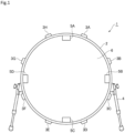
- FIG. 1 is a front view showing a configuration of a drum 1 that is the first example, not forming part of the present invention.
- the drum 1 is a bass drum.
- the drum 1 includes a barrel (shell) 2 that has a cylindrical shape with two open ends, eight lugs 3A to 3H, two legs 4, and four weights 5A to 5D.
- lugs 3A to 3H are not distinguished from each other, they are denoted as lugs 3, and when the weights 5A to 5D are not distinguished from each other, they are denoted as weights 5.
- FIG. 1 shows a state before a drumhead is attached to an open end of the shell 2. Although the drumhead is omitted from FIG. 1 , the drumhead is stretched over an open end of the shell 2 when the drum 1 is used.
- the opening diameter of the open end of the shell 2 is 22 inches, for example.
- the shell 2 is placed in an orientation in which a plane that includes the open end is orthogonal to the ground (in other words, an orientation in which the normal of the drumhead stretched over an open end is parallel to the ground).
- the shell 2 is supported by the legs 4, which are rod-shaped and extend from portions of the outer circumferential surface.
- the lugs 3 are provided on the outer circumferential surface of the shell 2. As shown in FIG. 1 , on the outer circumferential surface of the shell 2, the lug 3A is provided at a top right position, the lug 3B is provided at an upper right position, the lug 3C is provided at a lower right position, the lug 3D is provided at a bottom right position, the lug 3E is provided at a bottom left positon, the lug 3F is provided at a lower left position, the lug 3G is provided at an upper left position, and the lug 3H is provided at a top left position.
- the lugs 3A to 3H are provided at intervals of approximately 45 degrees in the circumferential direction of the shell 2.
- a tuning pin (not shown) for adjusting the tension of the drumhead is coupled to each of the lugs 3A to 3H.
- the weights 5 are members formed by processing a material with a relatively large specific gravity into blocks.
- the weights 5 have a columnar shape that is sufficiently short compared to the inner diameter of the shell 2.
- the specific shape of the weights 5 is not limited to this example.
- the weights 5 may have the shape of a rectangular parallelepiped.
- the material of the weights 5 is iron, for example, but may be stainless steel, brass, zinc, etc.
- the weights 5 are provided so as to be dispersed at intervals in the circumferential direction of the shell 2, and are fixed to the inner circumferential surface of the shell 2. As shown in FIG. 1 , on the inner circumferential surface of the shell 2, the weight 5A is provided between the lugs 3H and 3A that are adjacent to each other in the circumferential direction of the shell 2, the weight 5B is provided between the lugs 3B and 3C that are adjacent to each other, the weight 5C is provided between the lugs 3D and 3E that are adjacent to each other, and the weight 5D is provided between the lugs 3F and 3G that are adjacent to each other.
- the weights 5A to 5D are provided at positions where the weights 5A to 5D have four-fold rotational symmetry in the circumferential direction of the shell 2 (in other words, at intervals of 90 degrees in the circumferential direction of the shell 2). Also, the weights 5 are each provided at the center point of a section between two lugs 3 that are adjacent to each other, in the circumferential direction of the shell 2.
- the shell 2 vibrates in response to the drumhead stretched over the open end vibrating.
- the vibration of the shell 2 is represented as a superposition of a plurality of vibration modes.
- the weights 5 are located as described above, and the positions are determined in view of the vibration modes of the shell 2. That is, the weights 5 are provided at or near positions where the vibration level of the shell in a certain vibration mode is higher than other positions of the shell when the weights 5 are not provided.
- the weights 5 are fixed to the inner circumferential surface of the shell 2 as described above.
- the shell 2 is provided with through holes (not shown) into which bolts (not shown) are inserted.
- the bolts are inserted into the through holes from the outside to the inside of the shell 2.
- the weights 5 are each provided with a groove (not shown). A portion of a bolt inserted into a through hole, which protrudes inward of the shell 2, engages with such a groove.
- Each bolt is fastened tight with the shell 2 sandwiched between its head and a weight 5.
- the weights 5 are fixed to the shell 2.
- the method for fixing the weights 5 to the shell 2 is not limited to this example.
- the weights 5 have a columnar shape, one end side of each weight 5 in the axial direction is fixed to the inner circumferential surface of the shell 2.
- the weights 5 have substantially the same mass.
- the mass of each weight 5 is approximately 1 kg.
- the total mass of the weights 5 fixed to the shell 2 is preferably within the range of 25% to 200% of the mass of a shell to which the weights 5 are not fixed (i.e. a typical shell).
- the mass of a typical shell of a bass drum is approximately 4 kg. Therefore, the total mass of the weights 5 fixed to the shell 2 is preferably within the range of approximately 1 kg, which is 25% of the mass of a typical shell, to approximately 8 kg, which is 200% of the mass of a typical shell.
- the mass of each weight 5 is approximately 1 kg
- the total mass of the weights 5 is approximately 4 kg, which is within the range of approximately 1 kg to approximately 8 kg. This concludes the configuration of the drum 1.
- the weights 5 are fixed to the shell 2. Therefore, in the drum 1, the shell 2 and the weights 5 are integrated into one piece, and the overall mass of the shell 2 is greater than that of a typical shell.
- the shell 2 vibrates in response to the drumhead vibrating.
- the shell 2 in a stationary state starts vibrating, the shell 2 has a tendency to remain in the stationary state due to inertia.
- the tendency to remain in a stationary state increases as the mass of the shell 2 increases. Therefore, in the drum 1 having the shell 2 with an increased mass, the vibration of the shell 2 is suppressed in a frequency range around the fundamental tone of the drum sound.
- a portion that instantaneously moves inward of the shell 2 and a portion that instantaneously moves outward of the shell 2 alternatingly appear in the circumferential direction of the shell 2.
- the number of such repetitive appearances in the circumferential direction of the shell 2 increases as the order of the vibration mode of the shell increases.
- a plurality of weights 5 are fixed at intervals in the circumferential direction of the shell 2. By providing intervals in the circumferential direction of the shell 2, it is possible to fix the weights 5 respectively to portions that move inward or outward of the shell 2 and that alternatively appear in the circumferential direction of the shell 2 (i.e.
- the vibration of the shell 2 is sustained due to inertia.
- the extent to which the vibration is sustained increases as the mass of the portions increases. Therefore, in the drum 1 in which a plurality of weights 5 are fixed to the shell 2 so as to be dispersed in the circumferential direction of the shell 2, the vibration of the shell 2 is sustained in certain frequency bands of the drum sound (specifically, the frequency bands of high order-side harmonics of the fundamental tone).
- the weights 5 are fixed at certain positions in view of the vibration mode of the shell 2, i.e. positions where the weights 5 have four-fold rotational symmetry in the circumferential direction of the shell 2.
- the drum 1 it is possible to efficiently sustain the vibration of the shell 2 in the frequency bands of high order-side harmonics of the fundamental tone. Therefore, with the drum 1, it is possible to efficiently reduce the sustain of high order-side harmonics of the fundamental tone.
- the total mass of the weights 5 and the mass of each weight 5 are determined so that the total mass of the weights 5 is within the range of 25% to 200% of the mass of a typical shell.
- the drum 1 produces sound that contains the fundamental tone with increased sustain and the high order-side harmonics of the fundamental tone with reduced sustain. That is, with the drum 1, it is possible to obtain drum sound with higher quality in which a low tone (i.e. the fundamental tone) is clearer and more distinctive than that in the sound of a typical drum.
- a low tone i.e. the fundamental tone
- the weights 5 are fixed to the inner circumferential surface of the shell 2, and the weights 5 are unobtrusive when the shell 2 is seen from the outside of the shell 2. Therefore, the external appearance of the drum 1 remains almost the same as that of a typical drum.
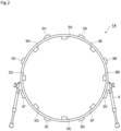
- FIG. 2 is a front view showing a configuration of a drum 1A that is the second modification, not forming part of the present invention.
- the drum 1A is different from the drum 1 according to the first example in that the drum 1A has weights 5E to 5H in addition to the weights 5A to 5D.
- the weights 5E to 5H are the same as the weights 5A to 5D. Also in the present example, when the weights 5A to 5H are not distinguished from each other, they are denoted as weights 5.
- weights 5 are fixed to the inner circumferential surface of the shell 2 so as to be dispersed in the circumferential direction of the shell 2.
- the weights 5A to 5D are provided at the same positions as those of the drum 1.
- the weight 5E is provided between the lugs 3A and 3B that are adjacent to each other in the circumferential direction of the shell 2
- the weight 5F is provided between the lugs 3C and 3D that are adjacent to each other
- the weight 5G is provided between the lugs 3E and 3F that are adjacent to each other
- the weight 5H is provided between the lugs 3G and 3H that are adjacent to each other.
- the weights 5Ato 5H according to the present embodiment are provided so as to have eight-fold rotational symmetry in the circumferential direction of the shell 2 (in other words, they are provided at intervals of 45 degrees in the circumferential direction of the shell 2).
- the number of weights 5 that are fixed to the shell 2 is increased compared to those in the drum 1, and the weights 5 are dispersed in the circumferential direction of the shell 2 at smaller intervals.
- the mass of each weight 5 according to the present example is approximately 0.5 kg, for example.
- the number of weights 5 in the drum 1A is eight, and therefore the total mass of the weights 5 in the drum 1A is approximately 4 kg in this case.
- the total mass of the weights 5 that are fixed to the shell 2 in the drum 1A is also within the range of 25% to 200% of the total mass of the shell to which the weights 5 are not fixed.
- the present example also achieves effects similar to those of the first example.
- the distribution of the weights 5 in the circumferential direction of the shell 2 is more uniform than that in the drum 1.
- the vibration of the shell 2 is presumably sustained in a wider range than in the drum 1, from harmonics that are close to the fundamental tone to high order-side harmonics that are away from the fundamental tone. Therefore, with the drum 1A, it is possible to efficiently reduce the sustain of high order-side harmonics of the fundamental tone in a wide frequency range.
- the drum 1A it is possible to obtain drum sound with higher quality than that of the drum 1.
- the number of lugs 3 and the number of the weights 5 are the same, and each weight 5 is provided at the center point between two lugs 3 that are adjacent to each other in the circumferential direction of the shell 2. That is, in the drum 1A, the lugs 3 and the weights 5 are alternatingly provided in the circumferential direction of the shell 2. As a result, the members with certain masses (the lugs 3 and the weights 5) are more uniformly provided on the shell 2 of the drum 1A than on that of the drum 1. Therefore, in the drum 1A, the influence of the shell 2 when vibrating and deforming is presumably more uniform in the circumferential direction of the shell 2 than that in the drum 1.
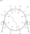
- FIG. 3 is a front view of a drum according to the invention.
- This drum 10 is also configured as a bass drum, for example.
- the drum 10 includes a shell 11 that has a cylindrical shape with two open ends.
- a drumhead 13 is stretched over an open end of the shell 11.
- the shell 11 is supported by rod-shaped legs 12, with two leg attachment portions 29, which are attached to the outer circumferential surface, being interposed between the shell 11 and the legs 12.
- the shell 11 is used in an orientation in which a plane that includes the open end is orthogonal to the ground (in other words, an orientation in which the normal of the drumhead 13 is parallel to the ground).
- a plurality of lugs 20 are provided on an outer circumferential surface 11b of the shell 11.
- the lugs 20 are provided in the circumferential direction of the shell 11 at equal intervals of approximately 45 degrees, and eight lugs 20 are provided in total.
- a tuning pin (not shown) for adjusting the tension of the drumhead 13 is coupled to each of the lugs 20.
- the lugs 20 are examples of functional parts that achieve a drum function (in this example, the function of adjusting the tension of the drumhead 13) when attached to the shell 11.
- a total of eight weights 30 are provided on an inner circumferential surface 11a of the shell 11 in correspondence with the lugs 20. Each weight 30 is provided on the opposite side of the lug 20 corresponding thereto with respect to the wall portion of the shell 11. Therefore, the weights 30 are dispersed at intervals in the circumferential direction of the shell 11.
- the material of the weights 30 is iron, for example, but may be stainless steel, brass, zinc, etc.
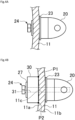
- FIGS. 4A and 4B are cross-sectional views of a portion around a lug 20 according to conventional art and an example not forming part of the present invention, respectively. These figures each show a cross section that is orthogonal to the direction in which the central axis of the shell 11 extends.
- the lug 20 is attached to the shell 11 from the outer circumferential surface-side, with a plate 23 being interposed therebetween, and the lug 20 is fastened to the shell 11 using a bolt 24 that is screwed into the lug 20 from the inner circumferential surface-side.
- FIG. 4C is an exploded view of a lug 20 and a weight 30 according to the present embodiment.
- FIG. 4D shows a bolt 24 and a weight 30 seen from the inner circumferential surface-side of the shell 11.
- the present embodiment is different from conventional art in that the drum 10 has the weights 30, but is the same as existing conventional drums in other configurations.
- the configurations of the lug 20, the plate 23, and the bolt 24 are the same as those of conventional art.
- the bolt 24 includes a head 26, a flange 27, and a shaft 25 ( FIG. 4C ). Note that, as a result of the weight 30 being provided, the length of the shaft 25 of the bolt 24 and the presence or absence of the flange 27 may be different from those of conventional art.
- the lug 20 has a screw hole 21 into which a tuning pin is screwed, and also has a screw hole 22 into which a bolt 24 is screwed ( FIG. 4C ).
- the screw hole 21 is substantially parallel to the direction in which the central axis of the shell 11 extends
- the screw hole 22 is substantially parallel to the radial direction of the shell 11 (the direction in which an axis C of the shaft 25 of the bolt 24 extends).
- the weight 30 has a cylindrical shape with a through hole 31 for fastening.
- the plate 23 and the shell 11 are respectively provided with through holes 23a and 11c for fastening.
- a worker places the plate 23 and the lug 20 on the outer circumferential surface 11b side of the shell 11, and places the weight 30 on the inner circumferential surface 11a side of the shell 11. Thereafter, the worker passes the shaft 25 of the bolt 24 through the through hole 31 of the weight 30, the through hole 11c of the shell 11, and the through hole 23a of the plate 23, from the inner circumferential surface 11a side of the shell 11, and screws the shaft 25 into the screw hole 22 of the lug 20.
- the weight 30 is fixed to the shell 11 in the state of being fastened together with the lug 20.
- the present example is different from conventional art only in that the weight 30 is interposed between the flange 27 of the bolt 24 and the inner circumferential surface 11a of the shell 11 when the lug 20 is to be fastened to the shell 11 using the bolt 24.
- This work process is the process of screwing one bolt 24, which is not different from that in conventional art.
- the weight 30 is cylindrical. Therefore, in a state where the weight 30 is fixed to the shell 11 ( FIGS. 4B and 4D ), the bolt 24 has a circular shape when seen in the axial direction of the shaft 25 (which is also the axial direction of the through hole 31), and has rotational symmetry with respect to the axis C of the shaft 25 (which is also the axis of the through hole 31). Therefore, the worker does not need to be careful about the orientation of the weight 30 in the circumferential direction. In addition, the external shape of the weight 30 and the inner diameter of the through hole 31 of the weight 30 are uniform. Therefore, there is no need to be careful about which of the two end faces should face the inner circumferential surface 11a of the shell 11. The above factors make work easier.
- the weight 30 is in contact with the inner circumferential surface 11a of the shell 11 at two points (contacting points P1 and P2) in the circumferential direction of the shell 11, which are opposite to each other with respect to the axis C of the shaft 25 of the bolt 24 in the circumferential direction of the shell 11.
- the weight 30 is stably fixed to the shell 11. Therefore, when the drum 10 is used (when the shell 11 vibrates as a result of being hit to be played), the weight 30 is not displaced independent of the shell 11, but is displaced together with the shell 11.
- the shell 11 and the weight 30 are integrated into one piece, and the overall mass of the shell 11 is greater than that of a conventional (existing) shell.
- the shell 11 vibrates in response to the drumhead 13 vibrating.
- the shell 11 in a stationary state starts vibrating, the shell 11 has a tendency to remain in the stationary state due to inertia.
- the tendency to remain in a stationary state increases as the mass of the shell 11 increases. Therefore, in the drum 10 having the shell 11 with an increased mass, the vibration of the shell 11 is suppressed in a frequency range around the fundamental tone of the drum sound.
- the vibration of the drumhead 13 decreases in certain frequency bands of the drum sound (specifically, the frequency bands of high order-side harmonics of the fundamental tone), and the sustain of the drum sound in certain frequency bands (specifically, the sustain of high order-side harmonics of the fundamental tone) decreases.
- the drumhead 13 vibrates more in a frequency range around the fundamental tone, and produces the fundamental tone with increased sustain.
- the fundamental tone with increased sustain leads to a clearer low tone.
- the total mass of the eight weights 30 that are fixed to the shell 11 is within the range of 25% to 200% of the mass of the shell 11 to which no weights 30 are fixed (i.e. a typical shell).
- the mass of a typical shell of a bass drum is approximately 4 kg. Therefore, it is preferable that the total mass of the plurality of weights 30 fixed to the shell 11 is greater than approximately 1 kg, which is 25% of the mass of a typical shell, and is smaller than approximately 8 kg, which is 200% of the mass of a typical shell.
- the weights 30 are fixed relative to the shell 11 in a state where the lugs 20 are fixed to the shell 11 using the bolts 24. Therefore, it is possible to increase the sustain of the fundamental tone.
- the weights 30 can be attached through an existing process of manufacturing a drum, or by a user who has purchased the drum. Therefore, it is possible to improve the sound quality of existing drums.
- the weights 30 are fixed to the shell 11 through the task of attaching the lugs 20 to the shell 11 using the bolts 24, and therefore there is no need to make the work process complex in order to attach the weights 30.
- the weights 30 are fixed to the shell 11 using the bolts 24, in the state of being fastened together with the lugs 20. Therefore, there is no need to provide a dedicated attachment mechanism, and application to existing drums is easy.
- a fastening member corresponding to one lug 20 is one bolt 24, and each weight 30 in a fixed state has a circular shape when seen in the axial direction of the bolt 24, and has rotational symmetry with respect to the axis C of the bolt 24.
- each weight 30 is in contact with the shell 11 at two contacting points P1 and P2 in the circumferential direction of the shell 11, which are opposite to each other with respect to the axis C of the bolt 24 in the circumferential direction of the shell 11. Therefore, the weight 30 is stably fixed to the shell 11, which enhances the effect of improving sound quality. Also, the total mass of the weights 30 fixed to the shell 11 is greater than 25% of the mass of the shell 11 to which no weights 30 are fixed, and therefore the fundamental tone has increased sustain.
- weights and the mode in which the weights are provided may be variously modified. Such modifications will be described with reference to FIGS. 5A to 5C , 6A to 6C , 7A, 7B , 8A, and 8B .
- FIGS. 5A, 5B , and 5C are cross-sectional views of weights according to modifications.
- a weight 32 shown in FIG. 5A has an inclined surface on one end surface side.
- the weight 32 also has a through hole 32a for fastening and a release hole 32b that is greater than the through hole 32a.
- the weight 32 has a circular shape when seen in the axial direction of the bolt 24, and has rotational symmetry with respect to the axis C of the bolt 24. Note that the bolt 24 does not need to have the flange 27, and if a bolt 24 without a flange 27 is used, the head 26 fills the release hole 32b.
- a plurality of weights may correspond to one lug 20.
- two weights 32 are combined as a set of weights, and the set of weights may be fixed to the shell 11 through an operation performed to screw one bolt 24. If end surfaces in which the through holes 32a are provided are in contact with each other, there is no need to be careful about which end surface of the set of weights should face the shell 11.
- the weights do not necessarily have the same shape.
- the weight 30 shown in FIG. 4C and so on may be combined with weights 32 such that the weights 32 sandwich the weight 30 ( FIG. 5C ). Also in this case, there is no need to be careful about which end surface of the set of combined weights should face the shell 11.
- three or more weights may be employed.
- One or more weights freely selected from among a plurality of weights may be fixed to either one or both of the lug 20 and the bolt 24.
- FIG. 6A is a side view of a bolt 24 according to a modification.
- a weight 33 may be formed integrally with a portion of the bolt 24 such as a portion between the head 26 and the shaft 25 as shown in FIG. 6A , instead of being separately provided. As a result, it is possible to fix the weight 33 to the shell 11 by carrying out the task of fastening the lug 20 using the bolt 24, which is the same as a conventional task.
- FIG. 6B is a cross sectional view of a portion around a lug 20, not forming part of the present invention.
- the weight 30 may be placed so as to face the outer circumferential surface 11b of the shell 11, and thus the weight 30 and the lug 20 may be fixed together to the shell 11 using the bolt 24 such that the weight 30 is interposed between the lug 20 and the outer circumferential surface 11b.
- the plate 23 may be provided, but is not essential.
- FIG. 6C is a cross sectional view of a lug 20, not forming part of the present invention. A weight may be built into the lug 20.
- a worker fastens the lug 20 to the shell 11 using the bolt 24, in the same mode as a conventional mode.
- a plurality of types of weights that can be attached to the lug 20 may be prepared, and a weight freely selected may be built into the lug 20. Whether or not to attach a weight to the lug 20 is also selectable.
- the head of the bolt 24 may be formed of a magnetic material
- the weight may be formed using a magnet
- the weight may be configured so as to fixable to the bolt 24 using a magnetic force. If this is the case, the area of the head of the bolt 24 with which the weight is in contact may be set large so that the weight is stable in a fixed state.
- the weight may be configured to be in contact with the shell 11 at two points in the circumferential direction of the shell 11, which are opposite to each other with respect to the axis C of the bolt 24. Therefore, linear contact or surface contact may be employed as contact with the shell 11.
- the shape of the weights 30 is not limited to a cylindrical shape, and may be a rectangular parallelepiped shape or the like.
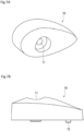
- FIG. 7A is a perspective view of a weight according to another modification falling under the scope of claim 1.
- FIG. 7B is a side view of the weight according to the other modification.
- FIG. 8A is a plan view of a lug according to the other modification.
- FIG. 8B is a side view of the lug according to the other modification.
- a weight 70 shown in FIGS. 7 A and 7B is paired with a lug 80 shown in FIGS. 8A and 8B .
- the drumhead 13 may be formed of a transparent film. If this is the case, the audience can see the weights 70 provided on the inner circumferential surface 11a of the shell 11, through the drumhead 13.
- the invention comprises a weight 70 that has a teardrop shape when seen in the axial direction of the shaft 25 of the bolt 24, whose lengthwise direction is substantially parallel to the axial direction of the shell 11, and that has a shape tapered in the axial direction of the shell 11.
- the weight 70 has a through hole 71 that penetrates therethrough in the thickness direction.
- the lug 80 has a screw hole 81 for fastening.
- the weight 70 has a protrusion 72 that protrudes toward the inner circumferential surface 11a of the shell 11, and when the weight 70 is fastened together with the lug 80, the protrusion 72 is in contact wtih the inner circumferential surface 11a of the shell 11. At this time, the force that fastens the weight 70 and the lug 80 together is concentrated at the protrusion 72, and a large frictional force is applied to the protrusion 72 from the inner circumferential surface 11a. As a result, the weight 70 is prevented from moving, especially from rotationally moving about the bolt 24. Thus, it is possible to prevent degradation in the appearance of the weight 70 due to the lengthwise direction of the weight 70 being displaced from the direction in which the central axis of the shell 11 extends.
- the head of the bolt 24 may be formed of a magnetic material, and the weight 30 may be formed using a magnet.
- the head of the bolt 24 may not be formed of a magnetic material, and only the weight 30 may be formed using a magnet. If this is the case, it is possible to directly or indirectly fix the weight 30 to the shell 11 using a magnetic force by using iron to form a portion of at least one of the shell 11, the lug 20, and the bolt 24. In this case, a fastening force of the bolt 24 may or may not be used to fix the weight 30 to the shell 11.
- a percussion instrument to which the present invention is applicable is not limited to a bass drum, and may be another drum such as a snare drum, a floor tom, a tom-tom, and so on, and furthermore, may be a timpani with a substantially conical shell.
- the functional parts that are to be attached to the shell may be any parts that achieve a certain function such as a drum function when attached to the shell, and are not limited to the lugs 20.
- they may be the leg attachment portions 29 ( FIG. 3 ) or pipe clamps.
- each weight 30 in the above-described embodiments has only one through hole 31 for fastening
- each weight may have a plurality of through holes for fastening. If this is the case, the shafts of a plurality of bolts that serve as the fastening members are inserted into the through holes and are screwed into a plurality of screw holes provided in the lugs.
Landscapes
- Physics & Mathematics (AREA)
- Engineering & Computer Science (AREA)
- Acoustics & Sound (AREA)
- Multimedia (AREA)
- Auxiliary Devices For Music (AREA)
- Golf Clubs (AREA)
- Electrophonic Musical Instruments (AREA)
Claims (7)
- Perkussionsinstrument (10), umfassend:eine im Wesentlichen zylindrische Trommel (11); undeine Vielzahl von Gewichten (70), die an der Trommel (11) fixiert sind, wobeidie Vielzahl von Gewichten (70) an der Trommel (11) in Intervallen in der Umfangsrichtung der Trommel (11) unter Verwendung jeweils eines einzelnen Bolzens (24) fixiert sind,und wobei das Perkussionsinstrument weiter ein funktionelles Teil (80) umfasst, das ausgebildet ist, um an der Trommel befestigt zu werden, undwobei die Gewichte (70) an einer inneren Umfangsfläche der Trommel (11) bereitgestellt sind, und wobei das funktionelle Teil (4) an einer äußeren Umfangsfläche der Trommel (11) befestigt ist, und dadurch gekennzeichnet, dassdie Gewichte (70) ein Loch (71) aufweisen, durch das der Bolzen einzuführen ist, undwobei die Gewichte (70) eine Tropfenform aufweisen, wenn sie in der axialen Richtung des Lochs gesehen werden, und so angeordnet sind, dass die Längsrichtung der Gewichte (70) im Wesentlichen parallel zur axialen Richtung der Trommel (11) ist,wobei die Gewichte (70) einen Vorsprung (72) aufweisen, der in Richtung der Trommel vorsteht, und der Vorsprung (72) in Kontakt mit der Trommel ist, wenn das Gewicht (70) durch den in das Loch (71) eingeführten Bolzen an dem funktionellen Teil (80) fixiert ist.
- Perkussionsinstrument nach Anspruch 1, wobei die Vielzahl von Gewichten (70) an der Trommel (11) an Positionen fixiert ist, an denen die Vielzahl von Gewichten eine Rotationssymmetrie in der Umfangsrichtung der Trommel (11) aufweist.
- Perkussionsinstrument nach einem der Ansprüche 1 bis 2, wobei die Gesamtmasse der an der Trommel (11) fixierten Gewichte (70) innerhalb des Bereichs von 25 % bis 200 % der Masse der Trommel (11) ist, an der die Gewichte nicht fixiert sind.
- Perkussionsinstrument nach einem der vorstehenden Ansprüche, wobei das Gewicht (70) an mindestens zwei Punkten in der Umfangsrichtung der Trommel (11) mit der Trommel (11) in Kontakt ist, wobei die zwei Punkte in Bezug auf den Bolzen (24) in der Umfangsrichtung der Trommel (11) einander gegenüberliegen.
- Perkussionsinstrument nach einem der Ansprüche 1, 2 oder 4,
wobei die Gesamtmasse der an der Trommel (11) fixierten Gewichte (70) größer ist als 25 % der Masse der Trommel (11), an der keines der Gewichte (70) fixiert ist. - Perkussionsinstrument nach einem der vorstehenden Ansprüche, wobei das funktionelle Teil (80) eine Lasche ist.
- Perkussionsinstrument nach einem der vorstehenden Ansprüche, wobei die Gewichte (70) magnetische Kraft aufweisen, mindestens eines aus der Trommel (11), dem funktionellen Teil (80) und dem Bolzen (24) Eisen enthält, und die Gewichte (70) an mindestens einem aus der Trommel (11), dem funktionellen Teil (80) und dem Bolzen (24) aufgrund der magnetischen Kraft fixiert sind.
Applications Claiming Priority (3)
| Application Number | Priority Date | Filing Date | Title |
|---|---|---|---|
| JP2016214856 | 2016-11-02 | ||
| JP2017039294 | 2017-03-02 | ||
| PCT/JP2017/038631 WO2018084057A1 (ja) | 2016-11-02 | 2017-10-26 | 打楽器 |
Publications (3)
| Publication Number | Publication Date |
|---|---|
| EP3537425A1 EP3537425A1 (de) | 2019-09-11 |
| EP3537425A4 EP3537425A4 (de) | 2020-06-17 |
| EP3537425B1 true EP3537425B1 (de) | 2024-08-28 |
Family
ID=62076925
Family Applications (1)
| Application Number | Title | Priority Date | Filing Date |
|---|---|---|---|
| EP17867652.4A Active EP3537425B1 (de) | 2016-11-02 | 2017-10-26 | Perkussionsinstrument |
Country Status (5)
| Country | Link |
|---|---|
| US (1) | US11114071B2 (de) |
| EP (1) | EP3537425B1 (de) |
| JP (1) | JP6835097B2 (de) |
| CN (1) | CN109891495B (de) |
| WO (1) | WO2018084057A1 (de) |
Families Citing this family (2)
| Publication number | Priority date | Publication date | Assignee | Title |
|---|---|---|---|---|
| US11207577B1 (en) | 2020-03-04 | 2021-12-28 | Cobra Golf Incorporated | Systems and methods for a weighted golf club head |
| US11033782B1 (en) * | 2020-03-04 | 2021-06-15 | Cobra Golf Incorporated | Systems and methods for a weighted golf club head |
Citations (1)
| Publication number | Priority date | Publication date | Assignee | Title |
|---|---|---|---|---|
| US20140290463A1 (en) * | 2013-03-26 | 2014-10-02 | Union Seimitsu Co., Ltd. | Head fixing mechanism of drum |
Family Cites Families (15)
| Publication number | Priority date | Publication date | Assignee | Title |
|---|---|---|---|---|
| JPH0622880Y2 (ja) * | 1988-05-17 | 1994-06-15 | ヤマハ株式会社 | ドラム用ラグ |
| JP2522735Y2 (ja) * | 1990-11-30 | 1997-01-16 | ヤマハ株式会社 | ドラム用ラグ取付構造 |
| US6291752B1 (en) * | 1996-07-22 | 2001-09-18 | Florentino S. Vergara | Drum shell structure |
| JP3140394B2 (ja) * | 1996-12-26 | 2001-03-05 | 東洋化成株式会社 | パチンコ機の掩蔽体の錠止方法 |
| JP3088691B2 (ja) * | 1997-10-16 | 2000-09-18 | 株式会社太鼓正 | 余韻増長器およびこれを装着した太鼓 |
| JP3140394U (ja) * | 2007-12-12 | 2008-03-27 | 善彦 矢野 | ドラム用音色調整材 |
| US20100037749A1 (en) * | 2008-02-04 | 2010-02-18 | Scott Alan Brunson | Drum rim system |
| US20100083812A1 (en) | 2008-10-02 | 2010-04-08 | Peavey Electronics Corporation | Acoustic Drum With Resonators Disposed Therein |
| US7932452B2 (en) * | 2009-08-05 | 2011-04-26 | Chang-Hui Chen | Extended low frequency resonant structure for drumhead |
| DE202009014729U1 (de) * | 2009-10-31 | 2010-01-07 | Roland Meinl Musikinstrumente Gmbh & Co. Kg | Trommelartiges Percussionsinstrument, insbesondere Timbale |
| FR3021802B1 (fr) * | 2014-05-30 | 2016-07-08 | Faustin Rubert Aigle | Instrument de musique a percussion du type membranophone muni d'un dispositif de reglage de la tension de la peau |
| US10376240B2 (en) | 2015-05-15 | 2019-08-13 | Siemens Medical Solutions Usa, Inc. | Contrast agent sensitive medical ultrasound imaging |
| JP2017039294A (ja) | 2015-08-21 | 2017-02-23 | セイコーエプソン株式会社 | 液体噴射装置 |
| CN204904819U (zh) * | 2015-09-16 | 2015-12-23 | 王景川 | 手鼓 |
| JP3202992U (ja) * | 2015-12-21 | 2016-03-03 | 万尋 港 | バチ及び太鼓型打楽器 |
-
2017
- 2017-10-26 WO PCT/JP2017/038631 patent/WO2018084057A1/ja not_active Ceased
- 2017-10-26 CN CN201780067147.4A patent/CN109891495B/zh active Active
- 2017-10-26 EP EP17867652.4A patent/EP3537425B1/de active Active
- 2017-10-26 JP JP2018548963A patent/JP6835097B2/ja active Active
-
2019
- 2019-04-29 US US16/397,170 patent/US11114071B2/en active Active
Patent Citations (1)
| Publication number | Priority date | Publication date | Assignee | Title |
|---|---|---|---|---|
| US20140290463A1 (en) * | 2013-03-26 | 2014-10-02 | Union Seimitsu Co., Ltd. | Head fixing mechanism of drum |
Also Published As
| Publication number | Publication date |
|---|---|
| JP6835097B2 (ja) | 2021-02-24 |
| US20190251934A1 (en) | 2019-08-15 |
| WO2018084057A1 (ja) | 2018-05-11 |
| EP3537425A4 (de) | 2020-06-17 |
| CN109891495A (zh) | 2019-06-14 |
| US11114071B2 (en) | 2021-09-07 |
| CN109891495B (zh) | 2023-07-04 |
| JPWO2018084057A1 (ja) | 2019-10-03 |
| EP3537425A1 (de) | 2019-09-11 |
Similar Documents
| Publication | Publication Date | Title |
|---|---|---|
| EP1284480B1 (de) | Zusammen mit verschiedenen Schlaginstrumenten verwendbares Trommelfell | |
| US9934764B2 (en) | Systems and methods for management of percussion accessories | |
| US8237038B2 (en) | Support system for acoustic instruments | |
| EP2690617B1 (de) | Schlingentrommel | |
| JP5987236B2 (ja) | 楽器及び枠体 | |
| JPS6046437B2 (ja) | セクシヨンに分けられた音楽用ドラム | |
| US10235978B2 (en) | Dual volume percussion instrument system | |
| JP6002023B2 (ja) | 棒状電子打楽器 | |
| US11114071B2 (en) | Percussion instrument | |
| US4993304A (en) | Multi-annular musical drum | |
| US20100083812A1 (en) | Acoustic Drum With Resonators Disposed Therein | |
| US10497345B2 (en) | Integral drum body system for percussion instrument | |
| JP3543730B2 (ja) | ドラム | |
| US9653053B2 (en) | Interchangeable drum bearing edge rings | |
| US9653054B1 (en) | Snare assembly for musical drum | |
| US10366681B2 (en) | Integrated lug and drum mount | |
| GB2577773A (en) | Multi-purpose drum | |
| US20160140938A1 (en) | Drum having interchangeable drum shell segments | |
| JP6439534B2 (ja) | ドラム | |
| JP7697198B2 (ja) | 打楽器駆動装置 | |
| Worland | Drum tuning: an experimental analysis of membrane modes under non-uniform tension | |
| JP2025006371A (ja) | 打楽器およびロッドの締付方法 | |
| US20220172697A1 (en) | Tone-enhancing drum shell and methods of making and using same | |
| JP2008281589A (ja) | 楽音装置並びに楽音装置の生産方法及び加工方法 | |
| JP2017191342A (ja) | 隔離された共鳴を提供するドラムラグホルダ及びドラム |
Legal Events
| Date | Code | Title | Description |
|---|---|---|---|
| STAA | Information on the status of an ep patent application or granted ep patent |
Free format text: STATUS: THE INTERNATIONAL PUBLICATION HAS BEEN MADE |
|
| PUAI | Public reference made under article 153(3) epc to a published international application that has entered the european phase |
Free format text: ORIGINAL CODE: 0009012 |
|
| STAA | Information on the status of an ep patent application or granted ep patent |
Free format text: STATUS: REQUEST FOR EXAMINATION WAS MADE |
|
| 17P | Request for examination filed |
Effective date: 20190515 |
|
| AK | Designated contracting states |
Kind code of ref document: A1 Designated state(s): AL AT BE BG CH CY CZ DE DK EE ES FI FR GB GR HR HU IE IS IT LI LT LU LV MC MK MT NL NO PL PT RO RS SE SI SK SM TR |
|
| AX | Request for extension of the european patent |
Extension state: BA ME |
|
| DAV | Request for validation of the european patent (deleted) | ||
| DAX | Request for extension of the european patent (deleted) | ||
| A4 | Supplementary search report drawn up and despatched |
Effective date: 20200519 |
|
| RIC1 | Information provided on ipc code assigned before grant |
Ipc: G10D 13/00 20200101AFI20200513BHEP Ipc: G10D 13/02 20200101ALI20200513BHEP Ipc: G10D 13/22 20200101ALI20200513BHEP Ipc: G10D 13/10 20200101ALI20200513BHEP |
|
| STAA | Information on the status of an ep patent application or granted ep patent |
Free format text: STATUS: EXAMINATION IS IN PROGRESS |
|
| 17Q | First examination report despatched |
Effective date: 20220621 |
|
| GRAP | Despatch of communication of intention to grant a patent |
Free format text: ORIGINAL CODE: EPIDOSNIGR1 |
|
| STAA | Information on the status of an ep patent application or granted ep patent |
Free format text: STATUS: GRANT OF PATENT IS INTENDED |
|
| INTG | Intention to grant announced |
Effective date: 20240430 |
|
| GRAS | Grant fee paid |
Free format text: ORIGINAL CODE: EPIDOSNIGR3 |
|
| GRAA | (expected) grant |
Free format text: ORIGINAL CODE: 0009210 |
|
| STAA | Information on the status of an ep patent application or granted ep patent |
Free format text: STATUS: THE PATENT HAS BEEN GRANTED |
|
| AK | Designated contracting states |
Kind code of ref document: B1 Designated state(s): AL AT BE BG CH CY CZ DE DK EE ES FI FR GB GR HR HU IE IS IT LI LT LU LV MC MK MT NL NO PL PT RO RS SE SI SK SM TR |
|
| REG | Reference to a national code |
Ref country code: GB Ref legal event code: FG4D |
|
| REG | Reference to a national code |
Ref country code: CH Ref legal event code: EP |
|
| REG | Reference to a national code |
Ref country code: DE Ref legal event code: R096 Ref document number: 602017084535 Country of ref document: DE |
|
| REG | Reference to a national code |
Ref country code: IE Ref legal event code: FG4D |
|
| REG | Reference to a national code |
Ref country code: LT Ref legal event code: MG9D |
|
| PG25 | Lapsed in a contracting state [announced via postgrant information from national office to epo] |
Ref country code: NO Free format text: LAPSE BECAUSE OF FAILURE TO SUBMIT A TRANSLATION OF THE DESCRIPTION OR TO PAY THE FEE WITHIN THE PRESCRIBED TIME-LIMIT Effective date: 20241128 |
|
| REG | Reference to a national code |
Ref country code: AT Ref legal event code: MK05 Ref document number: 1718867 Country of ref document: AT Kind code of ref document: T Effective date: 20240828 |
|
| PG25 | Lapsed in a contracting state [announced via postgrant information from national office to epo] |
Ref country code: NL Free format text: LAPSE BECAUSE OF FAILURE TO SUBMIT A TRANSLATION OF THE DESCRIPTION OR TO PAY THE FEE WITHIN THE PRESCRIBED TIME-LIMIT Effective date: 20240828 Ref country code: PT Free format text: LAPSE BECAUSE OF FAILURE TO SUBMIT A TRANSLATION OF THE DESCRIPTION OR TO PAY THE FEE WITHIN THE PRESCRIBED TIME-LIMIT Effective date: 20241230 Ref country code: GR Free format text: LAPSE BECAUSE OF FAILURE TO SUBMIT A TRANSLATION OF THE DESCRIPTION OR TO PAY THE FEE WITHIN THE PRESCRIBED TIME-LIMIT Effective date: 20241129 Ref country code: FI Free format text: LAPSE BECAUSE OF FAILURE TO SUBMIT A TRANSLATION OF THE DESCRIPTION OR TO PAY THE FEE WITHIN THE PRESCRIBED TIME-LIMIT Effective date: 20240828 Ref country code: PL Free format text: LAPSE BECAUSE OF FAILURE TO SUBMIT A TRANSLATION OF THE DESCRIPTION OR TO PAY THE FEE WITHIN THE PRESCRIBED TIME-LIMIT Effective date: 20240828 |
|
| PG25 | Lapsed in a contracting state [announced via postgrant information from national office to epo] |
Ref country code: BG Free format text: LAPSE BECAUSE OF FAILURE TO SUBMIT A TRANSLATION OF THE DESCRIPTION OR TO PAY THE FEE WITHIN THE PRESCRIBED TIME-LIMIT Effective date: 20240828 |
|
| PG25 | Lapsed in a contracting state [announced via postgrant information from national office to epo] |
Ref country code: LV Free format text: LAPSE BECAUSE OF FAILURE TO SUBMIT A TRANSLATION OF THE DESCRIPTION OR TO PAY THE FEE WITHIN THE PRESCRIBED TIME-LIMIT Effective date: 20240828 |
|
| REG | Reference to a national code |
Ref country code: NL Ref legal event code: MP Effective date: 20240828 |
|
| PG25 | Lapsed in a contracting state [announced via postgrant information from national office to epo] |
Ref country code: AT Free format text: LAPSE BECAUSE OF FAILURE TO SUBMIT A TRANSLATION OF THE DESCRIPTION OR TO PAY THE FEE WITHIN THE PRESCRIBED TIME-LIMIT Effective date: 20240828 Ref country code: IS Free format text: LAPSE BECAUSE OF FAILURE TO SUBMIT A TRANSLATION OF THE DESCRIPTION OR TO PAY THE FEE WITHIN THE PRESCRIBED TIME-LIMIT Effective date: 20241228 |
|
| PG25 | Lapsed in a contracting state [announced via postgrant information from national office to epo] |
Ref country code: HR Free format text: LAPSE BECAUSE OF FAILURE TO SUBMIT A TRANSLATION OF THE DESCRIPTION OR TO PAY THE FEE WITHIN THE PRESCRIBED TIME-LIMIT Effective date: 20240828 |
|
| PG25 | Lapsed in a contracting state [announced via postgrant information from national office to epo] |
Ref country code: RS Free format text: LAPSE BECAUSE OF FAILURE TO SUBMIT A TRANSLATION OF THE DESCRIPTION OR TO PAY THE FEE WITHIN THE PRESCRIBED TIME-LIMIT Effective date: 20241128 Ref country code: ES Free format text: LAPSE BECAUSE OF FAILURE TO SUBMIT A TRANSLATION OF THE DESCRIPTION OR TO PAY THE FEE WITHIN THE PRESCRIBED TIME-LIMIT Effective date: 20240828 |
|
| PG25 | Lapsed in a contracting state [announced via postgrant information from national office to epo] |
Ref country code: RS Free format text: LAPSE BECAUSE OF FAILURE TO SUBMIT A TRANSLATION OF THE DESCRIPTION OR TO PAY THE FEE WITHIN THE PRESCRIBED TIME-LIMIT Effective date: 20241128 Ref country code: PT Free format text: LAPSE BECAUSE OF FAILURE TO SUBMIT A TRANSLATION OF THE DESCRIPTION OR TO PAY THE FEE WITHIN THE PRESCRIBED TIME-LIMIT Effective date: 20241230 Ref country code: PL Free format text: LAPSE BECAUSE OF FAILURE TO SUBMIT A TRANSLATION OF THE DESCRIPTION OR TO PAY THE FEE WITHIN THE PRESCRIBED TIME-LIMIT Effective date: 20240828 Ref country code: NO Free format text: LAPSE BECAUSE OF FAILURE TO SUBMIT A TRANSLATION OF THE DESCRIPTION OR TO PAY THE FEE WITHIN THE PRESCRIBED TIME-LIMIT Effective date: 20241128 Ref country code: NL Free format text: LAPSE BECAUSE OF FAILURE TO SUBMIT A TRANSLATION OF THE DESCRIPTION OR TO PAY THE FEE WITHIN THE PRESCRIBED TIME-LIMIT Effective date: 20240828 Ref country code: LV Free format text: LAPSE BECAUSE OF FAILURE TO SUBMIT A TRANSLATION OF THE DESCRIPTION OR TO PAY THE FEE WITHIN THE PRESCRIBED TIME-LIMIT Effective date: 20240828 Ref country code: IS Free format text: LAPSE BECAUSE OF FAILURE TO SUBMIT A TRANSLATION OF THE DESCRIPTION OR TO PAY THE FEE WITHIN THE PRESCRIBED TIME-LIMIT Effective date: 20241228 Ref country code: HR Free format text: LAPSE BECAUSE OF FAILURE TO SUBMIT A TRANSLATION OF THE DESCRIPTION OR TO PAY THE FEE WITHIN THE PRESCRIBED TIME-LIMIT Effective date: 20240828 Ref country code: GR Free format text: LAPSE BECAUSE OF FAILURE TO SUBMIT A TRANSLATION OF THE DESCRIPTION OR TO PAY THE FEE WITHIN THE PRESCRIBED TIME-LIMIT Effective date: 20241129 Ref country code: FI Free format text: LAPSE BECAUSE OF FAILURE TO SUBMIT A TRANSLATION OF THE DESCRIPTION OR TO PAY THE FEE WITHIN THE PRESCRIBED TIME-LIMIT Effective date: 20240828 Ref country code: ES Free format text: LAPSE BECAUSE OF FAILURE TO SUBMIT A TRANSLATION OF THE DESCRIPTION OR TO PAY THE FEE WITHIN THE PRESCRIBED TIME-LIMIT Effective date: 20240828 Ref country code: BG Free format text: LAPSE BECAUSE OF FAILURE TO SUBMIT A TRANSLATION OF THE DESCRIPTION OR TO PAY THE FEE WITHIN THE PRESCRIBED TIME-LIMIT Effective date: 20240828 Ref country code: AT Free format text: LAPSE BECAUSE OF FAILURE TO SUBMIT A TRANSLATION OF THE DESCRIPTION OR TO PAY THE FEE WITHIN THE PRESCRIBED TIME-LIMIT Effective date: 20240828 |
|
| PG25 | Lapsed in a contracting state [announced via postgrant information from national office to epo] |
Ref country code: RO Free format text: LAPSE BECAUSE OF FAILURE TO SUBMIT A TRANSLATION OF THE DESCRIPTION OR TO PAY THE FEE WITHIN THE PRESCRIBED TIME-LIMIT Effective date: 20240828 Ref country code: SM Free format text: LAPSE BECAUSE OF FAILURE TO SUBMIT A TRANSLATION OF THE DESCRIPTION OR TO PAY THE FEE WITHIN THE PRESCRIBED TIME-LIMIT Effective date: 20240828 Ref country code: DK Free format text: LAPSE BECAUSE OF FAILURE TO SUBMIT A TRANSLATION OF THE DESCRIPTION OR TO PAY THE FEE WITHIN THE PRESCRIBED TIME-LIMIT Effective date: 20240828 |
|
| PG25 | Lapsed in a contracting state [announced via postgrant information from national office to epo] |
Ref country code: EE Free format text: LAPSE BECAUSE OF FAILURE TO SUBMIT A TRANSLATION OF THE DESCRIPTION OR TO PAY THE FEE WITHIN THE PRESCRIBED TIME-LIMIT Effective date: 20240828 |
|
| PG25 | Lapsed in a contracting state [announced via postgrant information from national office to epo] |
Ref country code: CZ Free format text: LAPSE BECAUSE OF FAILURE TO SUBMIT A TRANSLATION OF THE DESCRIPTION OR TO PAY THE FEE WITHIN THE PRESCRIBED TIME-LIMIT Effective date: 20240828 |
|
| PG25 | Lapsed in a contracting state [announced via postgrant information from national office to epo] |
Ref country code: IT Free format text: LAPSE BECAUSE OF FAILURE TO SUBMIT A TRANSLATION OF THE DESCRIPTION OR TO PAY THE FEE WITHIN THE PRESCRIBED TIME-LIMIT Effective date: 20240828 Ref country code: SK Free format text: LAPSE BECAUSE OF FAILURE TO SUBMIT A TRANSLATION OF THE DESCRIPTION OR TO PAY THE FEE WITHIN THE PRESCRIBED TIME-LIMIT Effective date: 20240828 |
|
| REG | Reference to a national code |
Ref country code: CH Ref legal event code: PL Ref country code: DE Ref legal event code: R097 Ref document number: 602017084535 Country of ref document: DE |
|
| PLBE | No opposition filed within time limit |
Free format text: ORIGINAL CODE: 0009261 |
|
| STAA | Information on the status of an ep patent application or granted ep patent |
Free format text: STATUS: NO OPPOSITION FILED WITHIN TIME LIMIT |
|
| PG25 | Lapsed in a contracting state [announced via postgrant information from national office to epo] |
Ref country code: MC Free format text: LAPSE BECAUSE OF FAILURE TO SUBMIT A TRANSLATION OF THE DESCRIPTION OR TO PAY THE FEE WITHIN THE PRESCRIBED TIME-LIMIT Effective date: 20240828 |
|
| PG25 | Lapsed in a contracting state [announced via postgrant information from national office to epo] |
Ref country code: BE Free format text: LAPSE BECAUSE OF NON-PAYMENT OF DUE FEES Effective date: 20241031 Ref country code: LU Free format text: LAPSE BECAUSE OF NON-PAYMENT OF DUE FEES Effective date: 20241026 |
|
| PG25 | Lapsed in a contracting state [announced via postgrant information from national office to epo] |
Ref country code: FR Free format text: LAPSE BECAUSE OF NON-PAYMENT OF DUE FEES Effective date: 20241028 |
|
| PG25 | Lapsed in a contracting state [announced via postgrant information from national office to epo] |
Ref country code: CH Free format text: LAPSE BECAUSE OF NON-PAYMENT OF DUE FEES Effective date: 20241031 |
|
| 26N | No opposition filed |
Effective date: 20250530 |
|
| REG | Reference to a national code |
Ref country code: BE Ref legal event code: MM Effective date: 20241031 |
|
| PG25 | Lapsed in a contracting state [announced via postgrant information from national office to epo] |
Ref country code: SE Free format text: LAPSE BECAUSE OF FAILURE TO SUBMIT A TRANSLATION OF THE DESCRIPTION OR TO PAY THE FEE WITHIN THE PRESCRIBED TIME-LIMIT Effective date: 20240828 |
|
| PG25 | Lapsed in a contracting state [announced via postgrant information from national office to epo] |
Ref country code: IE Free format text: LAPSE BECAUSE OF NON-PAYMENT OF DUE FEES Effective date: 20241026 |
|
| PGFP | Annual fee paid to national office [announced via postgrant information from national office to epo] |
Ref country code: DE Payment date: 20251021 Year of fee payment: 9 |
|
| PGFP | Annual fee paid to national office [announced via postgrant information from national office to epo] |
Ref country code: GB Payment date: 20251022 Year of fee payment: 9 |
|
| PG25 | Lapsed in a contracting state [announced via postgrant information from national office to epo] |
Ref country code: CY Free format text: LAPSE BECAUSE OF FAILURE TO SUBMIT A TRANSLATION OF THE DESCRIPTION OR TO PAY THE FEE WITHIN THE PRESCRIBED TIME-LIMIT; INVALID AB INITIO Effective date: 20171026 |
|
| PG25 | Lapsed in a contracting state [announced via postgrant information from national office to epo] |
Ref country code: HU Free format text: LAPSE BECAUSE OF FAILURE TO SUBMIT A TRANSLATION OF THE DESCRIPTION OR TO PAY THE FEE WITHIN THE PRESCRIBED TIME-LIMIT; INVALID AB INITIO Effective date: 20171026 |