EP3536650A1 - Control device for a hose lifter and hose lifter - Google Patents
Control device for a hose lifter and hose lifter Download PDFInfo
- Publication number
- EP3536650A1 EP3536650A1 EP18160918.1A EP18160918A EP3536650A1 EP 3536650 A1 EP3536650 A1 EP 3536650A1 EP 18160918 A EP18160918 A EP 18160918A EP 3536650 A1 EP3536650 A1 EP 3536650A1
- Authority
- EP
- European Patent Office
- Prior art keywords
- valve
- operating device
- tube
- blocking member
- flow path
- Prior art date
- Legal status (The legal status is an assumption and is not a legal conclusion. Google has not performed a legal analysis and makes no representation as to the accuracy of the status listed.)
- Granted
Links
- 230000000903 blocking effect Effects 0.000 claims abstract description 44
- 238000009423 ventilation Methods 0.000 claims abstract description 39
- 238000013022 venting Methods 0.000 claims abstract description 25
- 230000008878 coupling Effects 0.000 claims description 13
- 238000010168 coupling process Methods 0.000 claims description 13
- 238000005859 coupling reaction Methods 0.000 claims description 13
- 230000007246 mechanism Effects 0.000 claims description 7
- 230000007935 neutral effect Effects 0.000 claims description 6
- 238000004891 communication Methods 0.000 claims description 3
- 238000003825 pressing Methods 0.000 claims 2
- 239000012080 ambient air Substances 0.000 description 8
- 239000003570 air Substances 0.000 description 7
- 230000004941 influx Effects 0.000 description 3
- 230000006378 damage Effects 0.000 description 2
- 230000000694 effects Effects 0.000 description 2
- 230000007613 environmental effect Effects 0.000 description 2
- 230000003993 interaction Effects 0.000 description 2
- 238000007789 sealing Methods 0.000 description 2
- 238000004904 shortening Methods 0.000 description 2
- 230000007704 transition Effects 0.000 description 2
- 208000027418 Wounds and injury Diseases 0.000 description 1
- 238000005276 aerator Methods 0.000 description 1
- 238000013459 approach Methods 0.000 description 1
- 230000008901 benefit Effects 0.000 description 1
- 230000000981 bystander Effects 0.000 description 1
- 230000008859 change Effects 0.000 description 1
- 239000012530 fluid Substances 0.000 description 1
- 230000005484 gravity Effects 0.000 description 1
- 208000014674 injury Diseases 0.000 description 1
Images


Classifications
-
- B—PERFORMING OPERATIONS; TRANSPORTING
- B25—HAND TOOLS; PORTABLE POWER-DRIVEN TOOLS; MANIPULATORS
- B25J—MANIPULATORS; CHAMBERS PROVIDED WITH MANIPULATION DEVICES
- B25J15/00—Gripping heads and other end effectors
- B25J15/06—Gripping heads and other end effectors with vacuum or magnetic holding means
- B25J15/0616—Gripping heads and other end effectors with vacuum or magnetic holding means with vacuum
-
- B—PERFORMING OPERATIONS; TRANSPORTING
- B66—HOISTING; LIFTING; HAULING
- B66C—CRANES; LOAD-ENGAGING ELEMENTS OR DEVICES FOR CRANES, CAPSTANS, WINCHES, OR TACKLES
- B66C1/00—Load-engaging elements or devices attached to lifting or lowering gear of cranes or adapted for connection therewith for transmitting lifting forces to articles or groups of articles
- B66C1/02—Load-engaging elements or devices attached to lifting or lowering gear of cranes or adapted for connection therewith for transmitting lifting forces to articles or groups of articles by suction means
- B66C1/0212—Circular shape
-
- B—PERFORMING OPERATIONS; TRANSPORTING
- B66—HOISTING; LIFTING; HAULING
- B66C—CRANES; LOAD-ENGAGING ELEMENTS OR DEVICES FOR CRANES, CAPSTANS, WINCHES, OR TACKLES
- B66C1/00—Load-engaging elements or devices attached to lifting or lowering gear of cranes or adapted for connection therewith for transmitting lifting forces to articles or groups of articles
- B66C1/02—Load-engaging elements or devices attached to lifting or lowering gear of cranes or adapted for connection therewith for transmitting lifting forces to articles or groups of articles by suction means
- B66C1/0256—Operating and control devices
-
- B—PERFORMING OPERATIONS; TRANSPORTING
- B66—HOISTING; LIFTING; HAULING
- B66C—CRANES; LOAD-ENGAGING ELEMENTS OR DEVICES FOR CRANES, CAPSTANS, WINCHES, OR TACKLES
- B66C1/00—Load-engaging elements or devices attached to lifting or lowering gear of cranes or adapted for connection therewith for transmitting lifting forces to articles or groups of articles
- B66C1/02—Load-engaging elements or devices attached to lifting or lowering gear of cranes or adapted for connection therewith for transmitting lifting forces to articles or groups of articles by suction means
- B66C1/0293—Single lifting units; Only one suction cup
Landscapes
- Engineering & Computer Science (AREA)
- Mechanical Engineering (AREA)
- Robotics (AREA)
- Manipulator (AREA)
- Self-Closing Valves And Venting Or Aerating Valves (AREA)
Abstract
Die Erfindung betrifft eine Bedienvorrichtung (20) für einen Schlauchheber (10) mit einer an einem Ende des Hubschlauches (12) angeordneten Sauggreifvorrichtung (16), wobei die Bedienvorrichtung (20) einen Sauganschluss (30) zur Strömungsverbindung mit der Sauggreifvorrichtung (16), einen Hubschlauchanschluss (32) zur Strömungsverbindung mit dem Schlauchinnenraum (14) des Hubschlauchs (12) sowie eine Ventileinrichtung (36) zur Steuerung der Strömungsverbindungen aufweist, wobei die Ventileinrichtung (36) ein Sperrorgan (42), ein Belüftungsventil (44) und ein Steuerventil (46) umfasst, wobei die Ventileinrichtung (36) derart ausgebildet ist, dass das Steuerventil (46) unabhängig von der Stellung des Sperrorgans (42) einstellbar ist, und wobei die Ventileinrichtung (36) derart ausgebildet ist, dass dann, wenn das Belüftungsventil (44) in die Belüftungsstellung verstellt ist, stets das Sperrorgan (42) den Strömungsweg zwischen Schlauchinnenraum (14) und Sauggreifvorrichtung (16) absperrt. Die Erfindung betrifft außerdem einen Schlauchheber (10) mit einer solchen Bedienvorrichtung (20) .The invention relates to an operating device (20) for a tube lifter (10) having a suction gripping device (16) arranged at one end of the lifting tube (12), wherein the operating device (20) has a suction connection (30) for the flow connection with the suction gripping device (16). a Hubschlauchanschluss (32) for flow connection with the hose interior (14) of the Hubschlauchs (12) and a valve means (36) for controlling the flow connections, wherein the valve means (36) a blocking member (42), a vent valve (44) and a control valve (46), wherein the valve means (36) is formed such that the control valve (46) is adjustable independently of the position of the blocking member (42), and wherein the valve means (36) is formed such that when the venting valve (44) is adjusted to the ventilation position, always the blocking member (42) the flow path between the tube interior (14) and suction gripping device (16) shuts off. The invention also relates to a tube lifter (10) with such an operating device (20).
Description
Die Erfindung betrifft eine Bedienvorrichtung sowie einen Schlauchheber, der mit einer solchen Bedienvorrichtung ausgestattet ist.The invention relates to an operating device and a tube lifter, which is equipped with such an operating device.
Schlauchheber sind Unterdruck-Handhabungsvorrichtungen mit welchen Lasten von Hilfe Unterdruck gegriffen, angehoben und gegebenenfalls verlagert werden können. Die Hubkraft wird mit einem Hubschlauch ausgeübt, d.h. einem reversibel entlang seiner Längsausdehnung verformbaren, in der Regel faltenbalgartig ausgebildeten Schlauch, der durch Beaufschlagung seines Schlauchinnenraums mit Unterdruck verkürzbar und durch Abbau des in ihm herrschenden Unterdrucks wieder verlängerbar ist. An einem Ende des Hubschlauches ist in der Regel eine Sauggreifvorrichtung angeschlossen. Der für die Sauggreifvorrichtung erforderliche Unterdruck wird in der Regel durch den im Hubschlauch herrschenden Unterdruck bereitgestellt.Tube lifters are vacuum handling devices with which loads can be grabbed, lifted and possibly relocated by help of vacuum. The lifting force is exerted with a lifting tube, ie a reversibly deformable along its longitudinal extent, usually bellows-shaped hose, which can be shortened by applying its hose interior with negative pressure and by extending the prevailing negative pressure in it again extendable. At one end of the Lifting hose is usually connected to a suction gripping device. The vacuum required for the suction gripping device is generally provided by the negative pressure prevailing in the lifting hose.
Um den Hubschlauch zu bedienen, insbesondere um den im Hubschlauch herrschenden Unterdruck einzustellen und bei Bedarf durch kontrolliertes Zuströmen von Umgebungsluft abzubauen, sind verschiedenartige Bedienvorrichtungen bekannt. Mittels der Bedienvorrichtungen wird in der Regel auch der Unterdruck-Zustand in der Sauggreifvorrichtung des Schlauchhebers gesteuert. Solche Bedienvorrichtungen umfassen in der Regel eine oder mehrere Ventileinrichtungen.In order to operate the lifting tube, in particular in order to adjust the prevailing in the lifting tube negative pressure and, if necessary, reduce by controlled inflow of ambient air, various operating devices are known. By means of the operating devices, the negative pressure state in the suction gripping device of the tube lifter is controlled as a rule. Such operating devices usually comprise one or more valve devices.
Die
Die
Derartige Bedienvorrichtungen ermöglichen eine intuitive Bedienung, wobei zunächst der Hubschlauch belüftet wird und dadurch ein Verlängern des Hubschlauches unter Wirkung der Gewichtskraft der Last eingeleitet wird. Erst dann, bei weiterer Betätigung des entsprechenden Steuerelements erfolgt eine vollständige Belüftung, die ein Ablösen des angesaugten Gegenstandes ermöglicht. Allerdings ist der Hubschlauch in belüftetem Zustand nicht mehr kontrolliert verkürzbar und verlängerbar, sondern verbleibt zunächst in seinem verlängerten Zustand.Such operating devices allow intuitive operation, wherein initially the lifting tube is ventilated and thereby lengthening of the lifting tube is initiated under the effect of the weight of the load. Only then, with further actuation of the corresponding control is a complete ventilation, which allows detachment of the sucked object. However, the lifting tube in the ventilated state is no longer controlled shortened and extendable, but initially remains in its extended state.
In der
Bei den bekannten Vorrichtungen kann eine zusätzliche Belüftung durch das Belüftungsventil zu unerwünschten Längenänderungen des Hubschlauches führen. Dies ist insbesondere problematisch, wenn ein angesaugter Gegenstand losgelassen werden soll und der Hubschlauch gleichzeitig seine Länge verändert. Dadurch kann z.B. das abgelegte Werkstück verkippen oder verrutschen.In the known devices, additional ventilation through the vent valve can lead to undesirable changes in length of the lifting tube. This is particularly problematic when a sucked object is to be released and the lifting tube simultaneously changes its length. Thereby, e.g. tilted or slipped the stored workpiece.
Außerdem besteht ein Risiko, dass durch schnelles Belüften die Sauggreifvorrichtung und die gehaltene Last zu schnell abgesenkt werden. Es kann auch nicht ausgeschlossen werden, dass im Extremfall durch vollständiges Betätigen des Steuerelements die Last ungewollt losgelassen wird. Insbesondere, wenn eine Last in großer Höhe gehalten wurde, kann es zu Beschädigung der Last und/oder zu Verletzungen von umstehenden Personen kommen.In addition, there is a risk that the suction gripping device and the held load are lowered too quickly by rapid venting. It can also not be ruled out that in extreme cases, the load is released unintentionally by completely actuating the control element. In particular, if a load has been kept at high altitude, damage to the load and / or injury to bystanders may result.
Der vorliegenden Erfindung liegt die Aufgabe zugrunde, die Bediensicherheit und Zuverlässigkeit für einen Schlauchheber zu verbessern.The present invention has for its object to improve the operating safety and reliability for a tube lifter.
Diese Aufgabe wird durch eine Bedienvorrichtung gemäß Anspruch 1 gelöst. Die Bedienvorrichtung ist zur Bedienung eines Schlauchhebers eingerichtet. Ein solcher Schlauchheber weist einen Hubschlauch auf, welcher einen Schlauchinnenraum einschließt. Durch Beaufschlagung des Schlauchinnenraums mit Unterdruck ist der Hubschlauch reversibel verkürzbar, und entsprechend durch Zufuhr von Luft (z.B. Umgebungsluft) in den Schlauchinnenraum wieder verlängerbar. An einem Ende des Hubschlauches ist eine Sauggreifvorrichtung angeschlossen, welche durch den Schlauchinnenraum mit Unterdruck versorgt wird. Mit dem anderen Ende ist der Hubschlauch insbesondere an einem geeigneten Träger oder Gerüst angeordnet.This object is achieved by an operating device according to claim 1. The operating device is set up to operate a tube lifter. Such a tube lifter has a lifting tube which encloses a tube interior. By subjecting the interior of the tube to negative pressure, the lifting tube can be shortened reversibly, and can accordingly be extended again by supplying air (eg ambient air) into the interior of the tube. At one end of the lifting tube is a Suction gripping device connected, which is supplied by the hose interior with negative pressure. With the other end of the lifting tube is arranged in particular on a suitable support or framework.
Die Bedienvorrichtung hat einen Sauganschluss zur Strömungsverbindung mit der angeschlossenen Sauggreifvorrichtung, einen Hubschlauchanschluss zur Strömungsverbindung mit dem Schlauchinnenraum des angeschlossenen Hubschlauches. Außerdem kann die Bedienvorrichtung wenigstens einen Umgebungszugang zum Einströmen von Luft aus der Umgebung aufweisen. Dieser Zugang kann z.B. durch Öffnungen in einem Gehäuse der Bedienvorrichtung gebildet sein. Die Bedienvorrichtung umfasst außerdem eine Ventileinrichtung zur Steuerung der verschiedenen Strömungsverbindungen, d.h. insbesondere der Strömungsverbindung zwischen Hubschlauch und Sauggreifvorrichtung sowie der Strömungsverbindung zwischen Hubschlauch und Umgebung und zwischen Sauggreifvorrichtung und Umgebung.The operating device has a suction connection for the flow connection with the connected suction gripping device, a lifting hose connection for the flow connection with the hose interior of the connected lifting hose. In addition, the operating device may have at least one environmental access for the inflow of air from the environment. This access can e.g. be formed by openings in a housing of the operating device. The operating device also comprises a valve device for controlling the various flow connections, i. in particular the flow connection between the lifting tube and suction gripping device and the flow connection between the lifting tube and the environment and between the suction gripping device and the environment.
Die Ventileinrichtung umfasst insbesondere drei funktionale Einheiten zur Bereitstellung von Ventilfunktionen. Zum einen ist ein Sperrorgan vorgesehen, das verschiedene Stellungen einnehmen kann und je nach seiner Stellung einen Strömungsweg zwischen dem Hubschlauchanschluss und dem Sauganschluss absperrt oder freigibt. Außerdem ist ein Belüftungsventil vorgesehen, welches in eine Haltestellung und in eine Belüftungsstellung verstellbar ist, wobei in Belüftungsstellung der Strömungsweg zwischen der Umgebung und der Sauggreifvorrichtung freigegeben ist und in der Haltestellung dieser Strömungsweg weitgehend verschlossen ist (insbesondere dicht verschlossen ist). Außerdem ist ein Steuerventil vorgesehen, das zwischen einer Schließstellung und einer Öffnungsstellung einstellbar ist, wobei in Öffnungsstellung ein Strömungsweg von dem Schlauchinnenraum zur Umgebung freigegeben ist und in Schließstellung dieser Strömungsweg im Wesentlichen verschlossen ist. Die Ventileinrichtung ist dabei derart ausgebildet, dass das Steuerventil auch unabhängig von der Stellung des Sperrorgans einstellbar ist.In particular, the valve device comprises three functional units for providing valve functions. On the one hand, a blocking member is provided which can assume different positions and, depending on its position, shuts off or releases a flow path between the lifting hose connection and the suction connection. In addition, a ventilation valve is provided, which is adjustable in a holding position and in a ventilation position, wherein in ventilation position, the flow path between the environment and the suction gripping device is released and in the holding position, this flow path is largely closed (in particular is tightly closed). In addition, a control valve is provided which is adjustable between a closed position and an open position, wherein in the open position, a flow path is released from the tube interior to the environment and in the closed position of this flow path is substantially closed. The valve device is designed such that the control valve is independent of the position of the locking member adjustable.
Die Ventileinrichtung ist außerdem derart ausgebildet, dass das Sperrorgan mit dem Belüftungsventil zwangsgekoppelt ist, und zwar insofern, dass dann, wenn das Belüftungsventil in die Belüftungsstellung verstellt ist, automatisch sichergestellt ist, dass das Sperrorgan den Strömungsweg zwischen Schlauchinnenraum und Sauggreifvorrichtung absperrt.The valve device is also designed such that the obturator is forcibly coupled to the vent valve, in the sense that when the vent valve is moved to the vent position, it is automatically ensured that the obturator shuts off the flow path between the tube interior and suction gripping device.
Mit dieser Bedienvorrichtung kann die Länge des Hubschlauches somit über das Steuerventil eingestellt werden. Der von dem Steuerventil beeinflusste Strömungsweg weist insofern einen definierten Strömungswiderstand auf, der das Steuerverhalten des Hubschlauches beeinflusst. Insbesondere ist dieser Strömungswiderstand derart, dass auch in Öffnungsstellung der Hubschlauch nicht schlagartig belüftet wird und aufgrund der Gewichtskraft nach unten sackt, sondern der Hubschlauch sich aufgrund des Zusammenspiels der Unterdruckversorgung des Hubschlauches und des Einströmens von Luft durch den Strömungswiderstand des Steuerventils sowie der wirkenden Gewichtskraft langsam und kontrolliert verlängert.With this operating device, the length of the lifting tube can thus be adjusted via the control valve. The flow path influenced by the control valve has a defined flow resistance, which influences the control behavior of the lift tube. In particular, this flow resistance is such that even in the open position of the lifting tube is not suddenly vented and due to the weight sags down, but the lifting tube due to the interaction of the vacuum supply of the lifting tube and the inflow of air through the flow resistance of the control valve and the acting weight force slow and controlled extended.
Durch Öffnen des Belüftungsventils wird die angeschlossene Sauggreifvorrichtung auf jeden Fall direkt belüftet und ein angesaugter Gegenstand wird somit zuverlässig abgelöst. Insbesondere ist es nicht erforderlich, dass die Sauggreifvorrichtung gegen eine Restsaugkraft von der Oberfläche des Gegenstandes abgekippt oder abgehebelt werden muss. Dies ist bei bekannten Bedienvorrichtungen teilweise der Fall und ist insbesondere bei Handhabung von Gegenständen auf hohen Stapeln problematisch, da eine Bedienperson dann mit ungünstiger Körperhaltung arbeiten muss.By opening the ventilation valve, the connected suction gripping device is in any case directly ventilated and a sucked object is thus reliably detached. In particular, it is not necessary that the suction gripping device must be tilted or levered against a residual suction from the surface of the article. This is partially the case with known control devices and is particularly problematic when handling objects on high stacks, as an operator then has to work with unfavorable posture.
Da das Steuerventil unabhängig von der Stellung des Sperrorgans einstellbar ist, bleibt die Länge des Hubschlauches kontrolliert mittels des Steuerventils einstellbar, auch wenn der Sauger durch das Belüftungsventil belüftet wird. Da mit der Belüftung stets auch das Sperrorgan schließt, kann eine ungewollte Längenänderung des Hubschlauches vermieden werden. Anders als bei einigen bekannten Lösungen gelangt durch die Belüftung der Sauggreifvorrichtung nicht zusätzlich Luft in den Hubschlauch. Dadurch wird die Bediensicherheit und Zuverlässigkeit des Schlauchhebers erhöht.Since the control valve is independent of the position of the locking member is adjustable, the length of the lifting tube controlled by the control valve remains adjustable, even if the sucker is vented through the vent valve. As with the ventilation always closes the locking member, an unwanted change in length of the lifting tube can be avoided. Unlike some known solutions does not get through the ventilation of Sauggreifvorrichtung additional air into the lifting tube. This increases the operating reliability and reliability of the tube lifter.
Um ein unbeabsichtigtes Belüften zu vermeiden, kann ein Sicherheitsmechanismus vorgesehen sein, welcher derart mit dem Steuerventil und dem Belüftungsventil zusammenwirkt, dass das Belüftungsventil nur dann in die Belüftungsstellung verstellbar ist, wenn das Steuerventil bereits in die Öffnungsstellung eingestellt ist. Hierdurch wird das Risiko minimiert, dass ein angesaugter Gegenstand aus großer Höhe fallengelassen wird.In order to avoid unintentional venting, a safety mechanism may be provided, which with such the control valve and the venting valve cooperates, that the venting valve is adjustable only in the venting position when the control valve is already set in the open position. This minimizes the risk that an aspirated object will be dropped from a great height.
Um die Kopplung von Belüftungsventil und Sperrorgan zu realisieren, kann ein gemeinsames, manuell betätigbares Bedienelement für das Sperrorgan und das Belüftungsventil vorgesehen sein. Dieses Bedienelement wirkt gemeinsam auf Belüftungsventil und Sperrorgan insofern, dass bei Betätigung des Bedienelements das Sperrorgan den Strömungsweg zwischen Schlauchinnenraum und Sauggreifvorrichtung absperrt und gleichzeitig das Belüftungsventil in die Belüftungsstellung verstellt wird. Ist das Bedienelement nicht betätigt, so nimmt es eine Ruhelage ein, wobei in der Ruhelage das Belüftungsventil in seiner Haltestellung vorliegt und das Sperrorgan den Strömungsweg zwischen Schlauchinnenraum und Sauggreifvorrichtung freigibt. Insbesondere ist das Bedienelement mit einem Federmittel in Richtung seiner Ruhelage vorgespannt, d.h. nur gegen eine Rückstellkraft aus der Ruhelage heraus betätigbar.In order to realize the coupling of ventilation valve and locking member, a common, manually operable control element for the locking member and the vent valve may be provided. This control element acts in common on vent valve and blocking member insofar that upon actuation of the operating element the blocking member shuts off the flow path between the tube interior and the suction gripping device and at the same time the venting valve is adjusted to the venting position. If the operating element is not actuated, it assumes a rest position, wherein in the rest position the venting valve is in its holding position and the blocking member releases the flow path between the tube interior and the suction gripping device. In particular, the operating element is biased with a spring means in the direction of its rest position, i. only actuated against a restoring force from the rest position out.
Zur weiteren Ausgestaltung ist das Bedienelement gegen eine Betätigung mechanisch blockiert, solange das Steuerventil nicht in seine Öffnungsstellung eingestellt ist. Beispielsweise ist ein mechanischer Anschlag für das Bedienelement vorgesehen, welcher erst wegbewegt wird, wenn das Steuerventil in seine Öffnungsstellung eingestellt wird.For further embodiment, the control element is mechanically blocked against actuation, as long as the control valve is not set in its open position. For example, a mechanical stop for the operating element is provided, which is moved away only when the control valve is set in its open position.
Der genannte Sicherheitsmechanismus kann z.B. über eine Kopplung der jeweiligen Betätigungselemente (z.B. Schieber, Abzug, Riegel) realisiert werden. Beispielsweise ist zur Betätigung des Steuerventils ein manuell zwischen einer Neutrallage und einer Endlage kontinuierlich betätigbares Steuerelement vorgesehen (z.B. Schieber, Abzug). Bei Betätigung des Steuerelements ausgehend von der Neutrallage in Richtung seiner Endlage wird das Steuerventil aus der Schließstellung in Richtung Öffnungsstellung verstellt. Zur Realisierung des Sicherheitsmechanismus kann dann zusätzlich ein verschwenkbarer bzw. verlagerbarer Sperrriegel vorgesehen sein, der eine Sperrstellung einnehmen kann, in welcher er das Bedienelement für das Belüftungsventil mechanisch gegen eine Betätigung blockiert. Zusätzlich kann ein bewegliches Kopplungsglied vorgesehen sein, welches derart mit dem Steuerelement für das Steuerventil und dem Sperrriegel für das Belüftungsventil zusammenwirkt, dass der Sperrriegel dann aus seiner Sperrstellung verschwenkt bzw. verlagert wird, wenn das Steuerelement in seine Endlage eingestellt wird.The said security mechanism can e.g. via a coupling of the respective actuators (e.g., slider, trigger, latch). For example, to operate the control valve there is provided a control element (e.g., gate, trigger) that is manually operable between a neutral position and an end position. Upon actuation of the control element, starting from the neutral position in the direction of its end position, the control valve is moved from the closed position in the direction of the open position. To realize the safety mechanism can then be additionally provided a pivotable or movable locking bolt, which can assume a blocking position in which it mechanically blocks the control element for the ventilation valve against actuation. In addition, a movable coupling member may be provided which cooperates with the control valve for the control valve and the locking bar for the venting valve, that the locking bar is then pivoted or displaced from its blocking position when the control is set in its final position.
Beispielsweise kann das Steuerelement einen Zapfen oder Vorsprung aufweisen, welcher in einem Langloch des Kopplungsgliedes geführt ist und erst bei Vorliegen der Endlage an einem Ende des Langloches anstößt und dadurch das Kopplungsglied bewegt wird, um den Sperrriegel aus der Sperrstellung zu verschwenken bzw. zu verlagern.For example, the control may have a pin or projection which is guided in a slot of the coupling member and abuts only at the presence of the end position at one end of the slot and thereby the coupling member is moved to pivot the locking bolt from the locking position or to relocate.
Das gemeinsame Bedienelement für Sperrorgan und Belüftungsventil einerseits und das Steuerelement für das Steuerventil andererseits sind vorzugsweise separat (insbesondere räumlich beabstandet voneinander) an der Bedienvorrichtung angeordnet. Beide Elemente sind aber vorzugsweise derart an der Bedienvorrichtung angeordnet, dass beide Elemente von einer Bedienperson bedient werden können, insbesondere beide Elemente mit derselben Hand.The common control element for blocking member and vent valve on the one hand and the control element for the control valve on the other hand are preferably arranged separately (in particular spatially spaced from each other) on the operating device. However, both elements are preferably arranged on the operating device such that both elements can be operated by an operator, in particular both elements with the same hand.
Denkbar ist auch, dass das Belüftungsventil und das Sperrorgan innerhalb der Ventileinrichtung miteinander mechanisch zwangsgekoppelt sind. Dadurch kann sichergestellt werden, dass durch eine Einstellung des Belüftungsventils in die Belüftungsstellung automatisch auch das Sperrorgan in diejenige Stellung verstellt wird, in welcher der Strömungsweg zwischen Hubschlauch und Sauggreifvorrichtung abgesperrt wird.It is also conceivable that the venting valve and the blocking member are mechanically positively coupled with each other within the valve means. This can ensure that by adjusting the ventilation valve in the ventilation position and the locking member is automatically adjusted in the position in which the flow path between the lifting tube and suction gripping device is shut off.
Eine zuverlässige Ausgestaltung ergibt sich dadurch, dass das Belüftungsventil nicht kontinuierlich verstellbar ausgebildet ist, sondern von einem diskret in Haltestellung und Belüftungsstellung schaltbaren Ventil bereitgestellt ist.A reliable embodiment results from the fact that the vent valve is not designed to be continuously adjustable, but is provided by a discretely switchable in holding position and ventilation position valve.
Ebenso kann das Sperrorgan als nicht kontinuierlich verstellbares Sperrorgan ausgebildet sein, welches nur diskret in seine zwei Stellungen schaltbar ist.Likewise, the locking member may be formed as a non-continuously adjustable locking member, which is only discretely switchable in its two positions.
Die diskreten Ausgestaltungen für Belüftungsventil und/oder Sperrorgan haben den Vorteil, dass die Präzision der Steuerung über das Steuerventil nicht beeinträchtigt wird, beispielsweise dadurch, dass durch nicht eindeutig definierte Stellungen von Belüftungsventil und/oder Sperrorgan zusätzlich Luft in den Hubschlauch einströmt. Insofern erlaubt diese Bedienvorrichtung eine Steuerung mit hoher Präzision.The discrete embodiments for vent valve and / or blocking member have the advantage that the precision of the Control via the control valve is not affected, for example, that additionally flows through not clearly defined positions of ventilation valve and / or blocking member air into the lifting tube. In this respect, this operating device allows control with high precision.
Bei einer besonders bevorzugten Ausgestaltung weist die Ventileinrichtung ein 3/2-Wegeventil auf, welches sowohl das Sperrorgan, als auch das Belüftungsventil bereitstellt. Das 3/2-Wegeventil weist definitionsgemäß drei Anschlüsse auf, wobei ein Anschluss mit dem Sauganschluss, ein weiterer Anschluss mit der Umgebung und ein dritter Anschluss mit dem Steuerventil und/oder dem Hubschlauchanschluss strömungsverbunden ist. Bei Vorliegen der Haltestellung ist der Sauganschluss über das 3/2-Wegeventil mit dem Hubschlauchanschluss und/oder dem Steuerventil verbunden. Bei Vorliegen der Belüftungsstellung ist der Sauganschluss über das 3/2-Wegeventil mit der Umgebung verbunden und gleichzeitig die Verbindung bzw. der Strömungsweg von dem Hubschlauchanschluss zu dem Sauganschluss abgesperrt.In a particularly preferred embodiment, the valve device has a 3/2-way valve, which provides both the obturator, and the vent valve. By definition, the 3/2-way valve has three connections, one connection to the suction connection, another connection to the environment and a third connection to the control valve and / or the lifting hose connection. When the holding position is present, the suction connection is connected via the 3/2-way valve with the Hubschlauchanschluss and / or the control valve. When the ventilation position is present, the suction connection is connected to the environment via the 3/2-way valve and at the same time the connection or the flow path from the lift hose connection to the suction connection is shut off.
Das Steuerventil ist, wie eingangs erwähnt, weitgehend unabhängig von dem Sperrorgan einstellbar. Insbesondere ist das Steuerventil auch dann in die Öffnungsstellung verstellbar, wenn das Sperrorgan den Strömungsweg zwischen Schlauchinnenraum und Sauggreifvorrichtung absperrt. Vorzugsweise ist dann auch vorgesehen, dass das Steuerventil auch wieder zurück in Richtung Schließstellung einstellbar ist. Insofern bleibt der Hubschlauch auch bei Belüftung der Sauggreifvorrichtung vollständig kontrollierbar.The control valve is, as mentioned above, largely independent of the locking member adjustable. In particular, the control valve is also adjustable in the open position when the blocking member shuts off the flow path between the hose interior and suction gripping device. Preferably then it is also provided that the control valve also back towards the closed position is adjustable. In this respect, the lifting tube remains fully controllable even with ventilation of the suction gripping device.
Nach einem vorteilhaften Aspekt der Erfindung sind das Steuerventil, das Sperrorgan und das Belüftungsventil zwischen dem Hubschlauchanschluss und dem Sauganschluss funktional in Serie geschaltet, d.h. die genannten Einheiten wirken entlang des Strömungsweges vom Hubschlauchanschluss zum Sauganschluss nacheinander. Insbesondere ist ausgehend von dem Hubschlauchanschluss zunächst das Belüftungsventil angeordnet und erlaubt einen kontrollierbaren Lufteinlass zum Hubschlauchanschluss. Danach, dem Strömungsweg folgend, ist das Sperrelement angeordnet, um kontrolliert den Strömungsweg zwischen Hubschlauchanschluss und Sauganschluss abzusperren bzw. freizugeben. Schließlich folgt das Belüftungsventil, um kontrolliert Luft zur Belüftung des Sauganschlusses zuzuführen. Der Hubschlauch mit seinem Schlauchinnenraum und die angeschlossene Sauggreifvorrichtung bilden insgesamt betrachtet ein globales Unterdrucksystem mit zwei funktionalen Unterdruckbereichen: Dem Hubschlauchsystem, über dessen Druckzustand die Verkürzung bzw. die Verlängerung des Hubschlauches gesteuert wird, und das Greifsystem mit der Sauggreifvorrichtung (die Sauggreifvorrichtung bildet mit einer anzusaugenden Oberfläche einen Saugraum aus, so dass durch Unterdruck in dem Saugraum die Oberfläche angesaugt werden kann). Durch die Kopplung von Sperrorgan und Belüftungsventil können die zwei funktionalen Bereiche entweder voneinander getrennt werden (Belüftungsstellung des Belüftungsventils und gleichzeitig Absperrung des Strömungsweges mittels des Sperrorgans), oder zu einem gemeinsamen Unterdrucksystem miteinander verbunden sein (Haltestellung). Bei Vorliegen der Belüftungsstellung ist der Sauggreifer funktional vom Hubschlauch getrennt und beeinflusst den Unterdruck im Hubschlauch nicht.According to an advantageous aspect of the invention, the control valve, the blocking member and the venting valve are functionally connected in series between the Hubschlauchanschluss and the suction port, ie said units act along the flow path from the Hubschlauchanschluss to the suction port sequentially. In particular, starting from the Hubschlauchanschluss first the venting valve is arranged and allows a controllable air inlet to the Hubschlauchanschluss. Thereafter, following the flow path, the blocking element is arranged in order to shut off or release the flow path between the lifting hose connection and the suction connection in a controlled manner. Finally, the vent valve follows to supply controlled air for ventilation of the suction port. The lifting tube with its inner tube space and the connected suction gripping device form a global negative pressure system with two functional vacuum areas: The Hubschlauchsystem, the pressure state, the shortening or extension of the Hubschlauches is controlled, and the gripping system with the Sauggreifvorrichtung (the suction device forms with a suctioned Surface of a suction chamber, so that by vacuum in the suction chamber, the surface can be sucked). By coupling the obturator and vent valve, the two functional areas can either be separated be (ventilation position of the ventilation valve and at the same time blocking the flow path by means of the blocking member), or be connected to a common vacuum system with each other (holding position). If the ventilation position is present, the suction pad is functionally separated from the lifting tube and does not affect the negative pressure in the lifting tube.
Vorteilhafterweise weist die Bedienvorrichtung einen Handgriff auf, der insbesondere ergonomisch ausgestaltet ist und von einer Bedienperson gegriffen werden kann (vorzugsweise einhändig). An dem Handgriff ist vorzugsweise das gemeinsames Bedienelement für das Sperrorgan und das Belüftungsventil angeordnet. Auch das betätigbare Steuerelement zur Einstellung des Steuerventils ist vorzugsweise an dem Handgriff angeordnet.Advantageously, the operating device has a handle, which in particular is designed ergonomically and can be gripped by an operator (preferably one-handed). On the handle, the common operating element for the locking member and the vent valve is preferably arranged. Also, the actuatable control element for adjusting the control valve is preferably arranged on the handle.
Die eingangs gestellte Aufgabe wird auch durch einen Schlauchheber der genannten Art gelöst, wobei dieser Schlauchheber mit der vorstehend beschriebenen Bedienvorrichtung ausgestattet ist. Dabei ist die Bedienvorrichtung über ihren Sauganschluss mit der Sauggreifvorrichtung verbunden und über ihren Hubschlauchanschluss mit dem Hubschlauch des Schlauchhebers verbunden.The object stated at the outset is also achieved by a tube lifter of the type mentioned, this tube lifter being equipped with the operating device described above. In this case, the operating device is connected via its suction connection with the suction gripping device and connected via its Hubschlauchanschluss with the lifting tube of the tube lifter.
Die Erfindung wird im Folgenden anhand der Figuren näher erläutert.The invention will be explained in more detail below with reference to FIGS.
Es zeigen:
-
Figur 1 : Skizzierte Darstellung eines Schlauchhebers mit einer Bedienvorrichtung; -
Figur 2 : Detailansicht der Bedienvorrichtung ausFigur 1 ; -
Figur 3 : Die Bedienvorrichtung in Schnittdarstellung mit geschlossenem Steuerventil und geschlossenem Belüftungsventil; -
Figur 4 : Die Bedienvorrichtung in Schnittdarstellung mit geöffnetem Steuerventil; -
Figur 5 : Die Bedienvorrichtung in Schnittdarstellung mit geöffnetem Steuerventil und geöffnetem Belüftungsventil sowie geschlossenem Sperrorgan; -
Figur 6 : Funktionsskizze für die Konfiguration gemäßFigur 3 ; -
Figur 7 : Funktionsskizze für die Konfiguration gemäßFigur 4 ; und -
Figur 8 : Funktionsskizze für die Konfiguration gemäßFigur 5 .
-
FIG. 1 : Sketched representation of a tube lifter with an operating device; -
FIG. 2 : Detail view of the operating device offFIG. 1 ; -
FIG. 3 : The operating device in section with closed control valve and closed vent valve; -
FIG. 4 : The control device in sectional view with open control valve; -
FIG. 5 : The operating device in sectional view with open control valve and open vent valve and closed blocking element; -
FIG. 6 : Function sketch for the configuration according toFIG. 3 ; -
FIG. 7 : Function sketch for the configuration according toFIG. 4 ; and -
FIG. 8 : Function sketch for the configuration according toFIG. 5 ,
In der folgenden Beschreibung sowie in den Figuren sind für identische oder einander entsprechende Merkmale jeweils dieselben Bezugszeichen verwendet.In the following description and in the figures, the same reference numerals are used for identical or corresponding features.
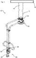
Die
Das untere Ende des Hubschlauches 12 ist mit einer Sauggreifvorrichtung 16 verbunden, die durch den Hubschlauch 12 mit Unterdruck versorgt wird. Mit seinem der Sauggreifvorrichtung 16 entgegengesetzten oberen Ende ist der Hubschlauch 12 mit einem Träger oder Gerüst 18 verbunden. Durch Verkürzen des Hubschlauches 12 kann somit die Sauggreifvorrichtung 14 und ein mit der Sauggreifvorrichtung 14 angesaugter Gegenstand (nicht dargestellt) angehoben werden.The lower end of the lifting
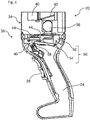
Um den Hubschlauch 12 sowie die Sauggreifvorrichtung 14 zu bedienen und zu steuern, ist eine Bedienvorrichtung 20 vorgesehen (Detailansicht vgl.
Im dargestellten Beispiel weist die Bedienvorrichtung 20 einen Anschlussabschnitt 22 auf, welcher mechanisch mit dem Hubschlauch 12 und der Sauggreifvorrichtung 14 verbunden ist. Die Verbindung ist dabei insbesondere derart ausgebildet, dass mittels der Bedienvorrichtung 20 auch Strömungsverbindungen zwischen dem Schlauchinnenraum 14 und der Sauggreifvorrichtungen 16, zwischen Schlauchinnenraum 14 und der Umgebung sowie zwischen Sauggreifvorrichtung 16 und der Umgebung gesteuert werden können. Hierzu weist die Bedienvorrichtung 20 eine Ventilvorrichtung auf, die weiter unten anhand der
Wie in den
Das Steuerelement 28 z.B. in der Art eines Pistolenabzugs ausgebildet, der ausgehend von einer Neutrallage (vgl.
Das Bedienelement 26 ist z.B. tastenartig ausgebildet und kann ausgehend von einer Ruhelage eingedrückt werden Insbesondere ist das Bedienelement 26 in seiner Ruhelage vorgespannt und kann nur gegen einer Rückstellkraft ausgehend von der Ruhelage betätigt werden.The operating
Die Bedienvorrichtung 20 weist einen Sauganschluss 30 auf, der im dargestellten Beispiel mittels einer rohrartigen Verbindungsleitung mit dem Anschlussabschnitt 22 verbunden ist und zur Strömungsverbindung mit der angeschlossenen Sauggreifvorrichtung 16 dient. Außerdem weist die Bedienvorrichtung 20 einen Hubschlauchanschluss 32 auf, der - im dargestellten Beispiel wiederum über den Anschlussabschnitt 22 - zur Strömungsverbindung mit dem angeschlossenen Hubschlauch 12 (genauer: dem Schlauchinnenraum 14) dient. Die Bedienvorrichtung 20 weist außerdem einen nicht näher dargestellten Umgebungszugang auf, welcher beispielsweise durch entsprechende Durchbrüche oder Öffnungen im Bereich des Handgriffs 24 gebildet sein können.The operating
Bei der dargestellten Bedienvorrichtung 20 ist der Anschlussabschnitt 22 räumlich weit beabstandet von dem Handgriff 24. Insbesondere verlaufen die rohrartigen Verbindungsleitungen zwischen dem Anschlussabschnitt 22 und dem Handgriff derart, dass im Betrieb des Schlauchhebers 10 die Sauggreifvorrichtung 16 vertikal versetzt (oberhalb) des Handgriffs positioniert ist. Diese Ausgestaltung erlaubt es, mit dem Schlauchheber Gegenstände von hohen Stapeln aufzunehmen und abzulegen.In the illustrated
Die Bedienvorrichtung 20 weist außerdem eine Ventileinrichtung 36 auf, die anhand der
Die
In den Schnittdarstellungen gemäß
Der Strömungsweg zwischen Kanal 40 und Querbohrung 38 kann mittels eines Sperrorgans 42 freigegeben oder abgesperrt werden. Im dargestellten Beispiel ist das Sperrorgan 42 als Ventilklappe ausgebildet, die in ihrer offenen Stellung ('
Darüber hinaus ist ein Belüftungsventil 44 vorgesehen, mit dem ein Strömungsweg von dem Sauganschluss 30 durch die Querbohrung 38 zur Umgebung freigegeben oder abgesperrt werden kann. Im dargestellten Beispiel weist das Belüftungsventil 44 ebenfalls eine Ventilklappe auf, die den genannten Strömungsweg freigibt oder absperrt. Das Belüftungsventil kann insofern eine Haltestellung einnehmen (gezeigt in
Die Ventileinrichtung 36 umfasst außerdem ein Steuerventil 46 mit einem verlagerbaren Ventilkörper 48, der an einem nicht näher dargestellten Dichtsitz anliegen kann oder von diesem entfernt werden kann. Das Steuerventil 46 ist zwischen einer Öffnungsstellung (gezeigt in
Das Steuerventil 46 ist mittels des Steuerelements 28 insbesondere kontinuierlich zwischen Öffnungsstellung und Schließstellung einstellbar. Je weiter das Steuerelement 28 eingedrückt wird (beispielsweise Übergang von der in
Das Sperrorgan 42 und das Belüftungsventil 44 werden gemeinsam von dem Bedienelement 26 (vgl.
Insofern kann mittels des gemeinsamen Bedienelements 26 eine mechanische Zwangskopplung von Sperrorgan und Belüftungsventil bereitgestellt werden.In this respect, by means of the
Die Bedienvorrichtung 20 umfasst insbesondere einen Sperrmechanismus 50, der sicherstellt, dass das Belüftungsventil 44 nur dann in die Belüftungsstellung verstellbar ist, wenn das Steuerventil 46 bereits in die Öffnungsstellung eingestellt ist.In particular, the operating
Der Sperrmechanismus 50 kann einen verschwenkbaren Sperrriegel 52 aufweisen, der derart angeordnet ist, dass er in einer Sperrstellung eine Verstellung des Belüftungsventils 44 blockiert. In der
Um diese Funktion zu realisieren, kann der Sperrmechanismus 50 ein bewegliches Kopplungsglied 54 aufweisen, welches im dargestellten Beispiel als Verbindungsarm ausgebildet ist, der einerseits mit dem Steuerelement 28 und andererseits mit dem Sperrriegel 52 zusammenwirkt. Bei Betätigung des Steuerelements 28 in seine Endlage (vgl.
Diese Funktionsweise kann beispielsweise dadurch realisiert werden, dass das Kopplungsglied ein Langloch 56 aufweist (vgl.
Aufgrund der gemeinsamen Betätigung von Sperrorgan 42 und Belüftungsventil 44 mittels des Bedienelements 26 bilden das Sperrorgan 42 und das Belüftungsventil 44 insgesamt ein diskret schaltbares 3/2-Wegeventil 58 (in
Das Steuerventil 46 ist insbesondere nicht mit dem Belüftungsventil 44 gekoppelt und kann grundsätzlich auch in der in
Bezüglich des Strömungsweges von dem Hubschlauchanschluss 32 durch den Kanal 40 und weiter durch die Querbohrung 38 zu dem Sauganschluss 30 sind das Steuerventil 46, das Sperrorgan 42 und schließlich das Belüftungsventil 44 seriell geschaltet. Dies wird anhand der Funktionsskizzen in den
In der
Ausgehend von dieser Konfiguration kann (durch Betätigung des Steuerelements 28, vgl.
Ist das Steuerventil 46 vollständig geöffnet (vgl.
Claims (13)
wobei die Ventileinrichtung (36) umfasst:
dadurch gekennzeichnet, dass die Ventileinrichtung (36) derart ausgebildet ist, dass dann, wenn das Belüftungsventil (44) in die Belüftungsstellung verstellt ist, stets das Sperrorgan (42) den Strömungsweg zwischen dem Hubschlauchanschluss (32) und dem Sauganschluss (30) absperrt.Operating device (20) for a tube lifter (10), which comprises a lifting tube (12) which has a tube interior (14) and can be shortened by applying pressure to the tube interior (14) with negative pressure, and with one at one end of the lifting tube (12). arranged suction gripping device (16) which is supplied through the tube interior (14) with negative pressure, wherein the operating device (20) has a suction port (30) for flow connection with the suction gripping device (16), a Hubschlauchanschluss (32) for flow communication with the tube interior (14 ) of the lifting tube (12) and a valve device (36) for controlling the flow connections,
wherein the valve means (36) comprises:
characterized in that the valve means (36) is designed such that when the vent valve (44) is moved into the venting position, always the blocking member (42) shuts off the flow path between the Hubschlauchanschluss (32) and the suction port (30).
Priority Applications (3)
| Application Number | Priority Date | Filing Date | Title |
|---|---|---|---|
| EP18160918.1A EP3536650B1 (en) | 2018-03-09 | 2018-03-09 | Control device for a hose lifter and hose lifter |
| US16/281,234 US10532469B2 (en) | 2018-03-09 | 2019-02-21 | Operating device for a tube lifter and tube lifter |
| CN201910170825.0A CN110240054B (en) | 2018-03-09 | 2019-03-07 | Handling device for a pipe lifter and pipe lifter |
Applications Claiming Priority (1)
| Application Number | Priority Date | Filing Date | Title |
|---|---|---|---|
| EP18160918.1A EP3536650B1 (en) | 2018-03-09 | 2018-03-09 | Control device for a hose lifter and hose lifter |
Publications (2)
| Publication Number | Publication Date |
|---|---|
| EP3536650A1 true EP3536650A1 (en) | 2019-09-11 |
| EP3536650B1 EP3536650B1 (en) | 2020-11-11 |
Family
ID=61622346
Family Applications (1)
| Application Number | Title | Priority Date | Filing Date |
|---|---|---|---|
| EP18160918.1A Active EP3536650B1 (en) | 2018-03-09 | 2018-03-09 | Control device for a hose lifter and hose lifter |
Country Status (3)
| Country | Link |
|---|---|
| US (1) | US10532469B2 (en) |
| EP (1) | EP3536650B1 (en) |
| CN (1) | CN110240054B (en) |
Cited By (1)
| Publication number | Priority date | Publication date | Assignee | Title |
|---|---|---|---|---|
| DE102020128380A1 (en) | 2020-10-28 | 2022-04-28 | AERO-LIFT Vakuumtechnik Gesellschaft mit beschränkter Haftung | tube lifter |
Families Citing this family (1)
| Publication number | Priority date | Publication date | Assignee | Title |
|---|---|---|---|---|
| CN114770849B (en) * | 2022-05-13 | 2023-04-25 | 东莞海博斯新材料科技有限公司 | Compression molding foaming equipment for preparing supercritical compression molding foaming elastomer |
Citations (6)
| Publication number | Priority date | Publication date | Assignee | Title |
|---|---|---|---|---|
| DE1778580U (en) * | 1958-08-18 | 1958-11-27 | Ludwig Maurer | DEVICE FOR HOLDING OBJECTS BY SUCTION. |
| WO1981002289A1 (en) | 1980-02-04 | 1981-08-20 | S Andersson | Lifting means for goods |
| DE3934922A1 (en) * | 1989-10-20 | 1991-04-25 | Schmalz J Gmbh | Hoist with suction box and suction connecting union - has vacuum pump actuated by radio control circuit as switch |
| WO2007094720A1 (en) | 2006-02-17 | 2007-08-23 | Pronomic Ab | Vacuum hoisting device |
| DE102008028205C5 (en) | 2008-06-09 | 2015-03-05 | J. Schmalz Gmbh | operating device |
| DE202016104731U1 (en) * | 2016-08-29 | 2016-09-16 | J. Schmalz Gmbh | Vacuum handling device |
Family Cites Families (16)
| Publication number | Priority date | Publication date | Assignee | Title |
|---|---|---|---|---|
| US2874989A (en) * | 1955-04-27 | 1959-02-24 | Ingersoll Rand Co | Control for hoists |
| US3696596A (en) * | 1970-03-23 | 1972-10-10 | Stanley C Wegscheid | Watermelon harvesting device |
| US4412775A (en) * | 1982-03-10 | 1983-11-01 | Multifold-International, Inc. | Vacuum assisted machine for handling articles |
| US4557659A (en) * | 1982-09-14 | 1985-12-10 | M. Scaglia S.P.A. | Device for supporting and handling loads by means of vacuum operated suction pads |
| US4749219A (en) * | 1986-10-30 | 1988-06-07 | Tek-Matik, Inc. | Vacuum lift assembly |
| GB9100056D0 (en) * | 1991-01-03 | 1991-02-20 | Palamatic Handling Syst | Valve arrangement |
| CN1046482C (en) * | 1995-06-22 | 1999-11-17 | 日本比索株式会社 | Vaccum-suction attachement pad |
| US5928537A (en) * | 1997-03-14 | 1999-07-27 | Fortune; William S. | Pneumatic pickup tool for small parts |
| DE19744190C2 (en) * | 1997-09-30 | 2000-08-03 | Schmalz J Gmbh | Vacuum handling device |
| DE19928734B4 (en) * | 1998-04-21 | 2007-08-23 | J. Schmalz Kg | Vacuum handling device |
| US6264259B1 (en) * | 2000-01-17 | 2001-07-24 | William S. Fortune | Hand held multicycle vacuum pump pickup tool |
| JP4582484B2 (en) * | 2006-12-20 | 2010-11-17 | Smc株式会社 | Vacuum adsorption device |
| KR101004600B1 (en) * | 2010-06-03 | 2010-12-28 | 주식회사 삼인이엔지 | Moving apparatus using vacuum absorption |
| CN202643149U (en) * | 2012-05-25 | 2013-01-02 | 绍兴县力锐家具制造有限公司 | Rotation type lifting conveying vacuum transporter |
| US9061868B1 (en) * | 2012-07-19 | 2015-06-23 | Wepco., Inc. | Vacuum-assisted carton or box lifter |
| SE1330060A1 (en) * | 2013-05-22 | 2014-11-18 | Vaculex Ab | Vacuum tube lifting device and lifting hose and method for controlling a vacuum tube lifting device |
-
2018
- 2018-03-09 EP EP18160918.1A patent/EP3536650B1/en active Active
-
2019
- 2019-02-21 US US16/281,234 patent/US10532469B2/en active Active
- 2019-03-07 CN CN201910170825.0A patent/CN110240054B/en active Active
Patent Citations (6)
| Publication number | Priority date | Publication date | Assignee | Title |
|---|---|---|---|---|
| DE1778580U (en) * | 1958-08-18 | 1958-11-27 | Ludwig Maurer | DEVICE FOR HOLDING OBJECTS BY SUCTION. |
| WO1981002289A1 (en) | 1980-02-04 | 1981-08-20 | S Andersson | Lifting means for goods |
| DE3934922A1 (en) * | 1989-10-20 | 1991-04-25 | Schmalz J Gmbh | Hoist with suction box and suction connecting union - has vacuum pump actuated by radio control circuit as switch |
| WO2007094720A1 (en) | 2006-02-17 | 2007-08-23 | Pronomic Ab | Vacuum hoisting device |
| DE102008028205C5 (en) | 2008-06-09 | 2015-03-05 | J. Schmalz Gmbh | operating device |
| DE202016104731U1 (en) * | 2016-08-29 | 2016-09-16 | J. Schmalz Gmbh | Vacuum handling device |
Cited By (3)
| Publication number | Priority date | Publication date | Assignee | Title |
|---|---|---|---|---|
| DE102020128380A1 (en) | 2020-10-28 | 2022-04-28 | AERO-LIFT Vakuumtechnik Gesellschaft mit beschränkter Haftung | tube lifter |
| EP3992135A1 (en) | 2020-10-28 | 2022-05-04 | AERO-LIFT Vakuumtechnik GmbH | Hose lifter |
| DE102020128380B4 (en) | 2020-10-28 | 2023-01-05 | AERO-LIFT Vakuumtechnik Gesellschaft mit beschränkter Haftung | tube lifter |
Also Published As
| Publication number | Publication date |
|---|---|
| CN110240054B (en) | 2021-03-09 |
| CN110240054A (en) | 2019-09-17 |
| US10532469B2 (en) | 2020-01-14 |
| US20190275684A1 (en) | 2019-09-12 |
| EP3536650B1 (en) | 2020-11-11 |
Similar Documents
| Publication | Publication Date | Title |
|---|---|---|
| EP2767365B1 (en) | Compressed air nail gun with a manually actuated trigger and a contact sensor | |
| EP2067638B2 (en) | Switching valve for raising and lowering a vehicle body | |
| EP3446833B1 (en) | Pneumatic nail gun with safety valve assembly | |
| DE3628424A1 (en) | CROSS-LINE DISCHARGE VALVE MECHANISM | |
| EP1299649B1 (en) | Vacuum generator | |
| EP3536650B1 (en) | Control device for a hose lifter and hose lifter | |
| EP3539916B1 (en) | Control device for a hose lifter | |
| DE202018100403U1 (en) | Operating device for a tube lifter and tube lifter | |
| WO2006084445A2 (en) | Door provided with a door brake | |
| DE102006055627A1 (en) | Piston operated interlock valve for a hydraulic actuator load check valve | |
| DE202016104731U1 (en) | Vacuum handling device | |
| DE19744327C1 (en) | Apparatus for stabilising guide rods of a tractor | |
| EP2223881B1 (en) | Vacuum hoisting device and method for operating a vacuum hoisting device | |
| DE102023102438B3 (en) | Operating device for a tube lifter and tube lifter | |
| DE102017118128A1 (en) | Locking device for locking a mechanism of an aircraft | |
| DE202013001537U1 (en) | Pneumatic nailer with a manually operated release and a touch probe | |
| DE102020107544A1 (en) | Hydraulic arrangement | |
| DE102021102572B4 (en) | tube lifter | |
| DE102013110420A1 (en) | control device | |
| EP3992135B1 (en) | Hose lifter | |
| DE202022106933U1 (en) | vacuum lifting device | |
| DE102011123106B3 (en) | Blind riveting tool | |
| DE102017002784A1 (en) | Control unit for a control device for a heavy-duty vehicle, in particular for a gooseneck, a lifting arrangement or a steering arrangement of a heavy-duty vehicle, and such a control device | |
| WO2016169967A1 (en) | Hydraulically actuatable pneumatic valve mechanism | |
| DE202005008248U1 (en) | Device for receiving, transporting and setting down of load has lifting sleeve connected to vacuum producer and connected to suction plate and guide arm, and connected by flow to control unit and to suction plate |
Legal Events
| Date | Code | Title | Description |
|---|---|---|---|
| PUAI | Public reference made under article 153(3) epc to a published international application that has entered the european phase |
Free format text: ORIGINAL CODE: 0009012 |
|
| STAA | Information on the status of an ep patent application or granted ep patent |
Free format text: STATUS: THE APPLICATION HAS BEEN PUBLISHED |
|
| AK | Designated contracting states |
Kind code of ref document: A1 Designated state(s): AL AT BE BG CH CY CZ DE DK EE ES FI FR GB GR HR HU IE IS IT LI LT LU LV MC MK MT NL NO PL PT RO RS SE SI SK SM TR |
|
| AX | Request for extension of the european patent |
Extension state: BA ME |
|
| STAA | Information on the status of an ep patent application or granted ep patent |
Free format text: STATUS: REQUEST FOR EXAMINATION WAS MADE |
|
| 17P | Request for examination filed |
Effective date: 20200311 |
|
| RBV | Designated contracting states (corrected) |
Designated state(s): AL AT BE BG CH CY CZ DE DK EE ES FI FR GB GR HR HU IE IS IT LI LT LU LV MC MK MT NL NO PL PT RO RS SE SI SK SM TR |
|
| GRAP | Despatch of communication of intention to grant a patent |
Free format text: ORIGINAL CODE: EPIDOSNIGR1 |
|
| STAA | Information on the status of an ep patent application or granted ep patent |
Free format text: STATUS: GRANT OF PATENT IS INTENDED |
|
| GRAJ | Information related to disapproval of communication of intention to grant by the applicant or resumption of examination proceedings by the epo deleted |
Free format text: ORIGINAL CODE: EPIDOSDIGR1 |
|
| INTG | Intention to grant announced |
Effective date: 20200422 |
|
| STAA | Information on the status of an ep patent application or granted ep patent |
Free format text: STATUS: REQUEST FOR EXAMINATION WAS MADE |
|
| INTG | Intention to grant announced |
Effective date: 20200429 |
|
| GRAP | Despatch of communication of intention to grant a patent |
Free format text: ORIGINAL CODE: EPIDOSNIGR1 |
|
| STAA | Information on the status of an ep patent application or granted ep patent |
Free format text: STATUS: GRANT OF PATENT IS INTENDED |
|
| INTC | Intention to grant announced (deleted) | ||
| INTG | Intention to grant announced |
Effective date: 20200608 |
|
| GRAS | Grant fee paid |
Free format text: ORIGINAL CODE: EPIDOSNIGR3 |
|
| GRAA | (expected) grant |
Free format text: ORIGINAL CODE: 0009210 |
|
| STAA | Information on the status of an ep patent application or granted ep patent |
Free format text: STATUS: THE PATENT HAS BEEN GRANTED |
|
| AK | Designated contracting states |
Kind code of ref document: B1 Designated state(s): AL AT BE BG CH CY CZ DE DK EE ES FI FR GB GR HR HU IE IS IT LI LT LU LV MC MK MT NL NO PL PT RO RS SE SI SK SM TR |
|
| REG | Reference to a national code |
Ref country code: GB Ref legal event code: FG4D Free format text: NOT ENGLISH |
|
| REG | Reference to a national code |
Ref country code: CH Ref legal event code: EP |
|
| REG | Reference to a national code |
Ref country code: AT Ref legal event code: REF Ref document number: 1333269 Country of ref document: AT Kind code of ref document: T Effective date: 20201115 |
|
| REG | Reference to a national code |
Ref country code: DE Ref legal event code: R096 Ref document number: 502018002954 Country of ref document: DE |
|
| REG | Reference to a national code |
Ref country code: IE Ref legal event code: FG4D Free format text: LANGUAGE OF EP DOCUMENT: GERMAN |
|
| REG | Reference to a national code |
Ref country code: NL Ref legal event code: MP Effective date: 20201111 |
|
| PG25 | Lapsed in a contracting state [announced via postgrant information from national office to epo] |
Ref country code: FI Free format text: LAPSE BECAUSE OF FAILURE TO SUBMIT A TRANSLATION OF THE DESCRIPTION OR TO PAY THE FEE WITHIN THE PRESCRIBED TIME-LIMIT Effective date: 20201111 Ref country code: RS Free format text: LAPSE BECAUSE OF FAILURE TO SUBMIT A TRANSLATION OF THE DESCRIPTION OR TO PAY THE FEE WITHIN THE PRESCRIBED TIME-LIMIT Effective date: 20201111 Ref country code: PT Free format text: LAPSE BECAUSE OF FAILURE TO SUBMIT A TRANSLATION OF THE DESCRIPTION OR TO PAY THE FEE WITHIN THE PRESCRIBED TIME-LIMIT Effective date: 20210311 Ref country code: NO Free format text: LAPSE BECAUSE OF FAILURE TO SUBMIT A TRANSLATION OF THE DESCRIPTION OR TO PAY THE FEE WITHIN THE PRESCRIBED TIME-LIMIT Effective date: 20210211 Ref country code: GR Free format text: LAPSE BECAUSE OF FAILURE TO SUBMIT A TRANSLATION OF THE DESCRIPTION OR TO PAY THE FEE WITHIN THE PRESCRIBED TIME-LIMIT Effective date: 20210212 |
|
| PG25 | Lapsed in a contracting state [announced via postgrant information from national office to epo] |
Ref country code: BG Free format text: LAPSE BECAUSE OF FAILURE TO SUBMIT A TRANSLATION OF THE DESCRIPTION OR TO PAY THE FEE WITHIN THE PRESCRIBED TIME-LIMIT Effective date: 20210211 Ref country code: IS Free format text: LAPSE BECAUSE OF FAILURE TO SUBMIT A TRANSLATION OF THE DESCRIPTION OR TO PAY THE FEE WITHIN THE PRESCRIBED TIME-LIMIT Effective date: 20210311 Ref country code: LV Free format text: LAPSE BECAUSE OF FAILURE TO SUBMIT A TRANSLATION OF THE DESCRIPTION OR TO PAY THE FEE WITHIN THE PRESCRIBED TIME-LIMIT Effective date: 20201111 Ref country code: PL Free format text: LAPSE BECAUSE OF FAILURE TO SUBMIT A TRANSLATION OF THE DESCRIPTION OR TO PAY THE FEE WITHIN THE PRESCRIBED TIME-LIMIT Effective date: 20201111 |
|
| REG | Reference to a national code |
Ref country code: LT Ref legal event code: MG9D |
|
| PG25 | Lapsed in a contracting state [announced via postgrant information from national office to epo] |
Ref country code: HR Free format text: LAPSE BECAUSE OF FAILURE TO SUBMIT A TRANSLATION OF THE DESCRIPTION OR TO PAY THE FEE WITHIN THE PRESCRIBED TIME-LIMIT Effective date: 20201111 |
|
| PG25 | Lapsed in a contracting state [announced via postgrant information from national office to epo] |
Ref country code: SK Free format text: LAPSE BECAUSE OF FAILURE TO SUBMIT A TRANSLATION OF THE DESCRIPTION OR TO PAY THE FEE WITHIN THE PRESCRIBED TIME-LIMIT Effective date: 20201111 Ref country code: RO Free format text: LAPSE BECAUSE OF FAILURE TO SUBMIT A TRANSLATION OF THE DESCRIPTION OR TO PAY THE FEE WITHIN THE PRESCRIBED TIME-LIMIT Effective date: 20201111 Ref country code: SM Free format text: LAPSE BECAUSE OF FAILURE TO SUBMIT A TRANSLATION OF THE DESCRIPTION OR TO PAY THE FEE WITHIN THE PRESCRIBED TIME-LIMIT Effective date: 20201111 Ref country code: EE Free format text: LAPSE BECAUSE OF FAILURE TO SUBMIT A TRANSLATION OF THE DESCRIPTION OR TO PAY THE FEE WITHIN THE PRESCRIBED TIME-LIMIT Effective date: 20201111 Ref country code: CZ Free format text: LAPSE BECAUSE OF FAILURE TO SUBMIT A TRANSLATION OF THE DESCRIPTION OR TO PAY THE FEE WITHIN THE PRESCRIBED TIME-LIMIT Effective date: 20201111 Ref country code: LT Free format text: LAPSE BECAUSE OF FAILURE TO SUBMIT A TRANSLATION OF THE DESCRIPTION OR TO PAY THE FEE WITHIN THE PRESCRIBED TIME-LIMIT Effective date: 20201111 |
|
| REG | Reference to a national code |
Ref country code: DE Ref legal event code: R097 Ref document number: 502018002954 Country of ref document: DE |
|
| PG25 | Lapsed in a contracting state [announced via postgrant information from national office to epo] |
Ref country code: DK Free format text: LAPSE BECAUSE OF FAILURE TO SUBMIT A TRANSLATION OF THE DESCRIPTION OR TO PAY THE FEE WITHIN THE PRESCRIBED TIME-LIMIT Effective date: 20201111 |
|
| PLBE | No opposition filed within time limit |
Free format text: ORIGINAL CODE: 0009261 |
|
| STAA | Information on the status of an ep patent application or granted ep patent |
Free format text: STATUS: NO OPPOSITION FILED WITHIN TIME LIMIT |
|
| 26N | No opposition filed |
Effective date: 20210812 |
|
| PG25 | Lapsed in a contracting state [announced via postgrant information from national office to epo] |
Ref country code: NL Free format text: LAPSE BECAUSE OF FAILURE TO SUBMIT A TRANSLATION OF THE DESCRIPTION OR TO PAY THE FEE WITHIN THE PRESCRIBED TIME-LIMIT Effective date: 20201111 Ref country code: AL Free format text: LAPSE BECAUSE OF FAILURE TO SUBMIT A TRANSLATION OF THE DESCRIPTION OR TO PAY THE FEE WITHIN THE PRESCRIBED TIME-LIMIT Effective date: 20201111 Ref country code: IT Free format text: LAPSE BECAUSE OF FAILURE TO SUBMIT A TRANSLATION OF THE DESCRIPTION OR TO PAY THE FEE WITHIN THE PRESCRIBED TIME-LIMIT Effective date: 20201111 Ref country code: MC Free format text: LAPSE BECAUSE OF FAILURE TO SUBMIT A TRANSLATION OF THE DESCRIPTION OR TO PAY THE FEE WITHIN THE PRESCRIBED TIME-LIMIT Effective date: 20201111 |
|
| REG | Reference to a national code |
Ref country code: CH Ref legal event code: PL |
|
| PG25 | Lapsed in a contracting state [announced via postgrant information from national office to epo] |
Ref country code: SI Free format text: LAPSE BECAUSE OF FAILURE TO SUBMIT A TRANSLATION OF THE DESCRIPTION OR TO PAY THE FEE WITHIN THE PRESCRIBED TIME-LIMIT Effective date: 20201111 |
|
| REG | Reference to a national code |
Ref country code: BE Ref legal event code: MM Effective date: 20210331 |
|
| PG25 | Lapsed in a contracting state [announced via postgrant information from national office to epo] |
Ref country code: ES Free format text: LAPSE BECAUSE OF FAILURE TO SUBMIT A TRANSLATION OF THE DESCRIPTION OR TO PAY THE FEE WITHIN THE PRESCRIBED TIME-LIMIT Effective date: 20201111 Ref country code: IE Free format text: LAPSE BECAUSE OF NON-PAYMENT OF DUE FEES Effective date: 20210309 Ref country code: FR Free format text: LAPSE BECAUSE OF NON-PAYMENT OF DUE FEES Effective date: 20210331 Ref country code: CH Free format text: LAPSE BECAUSE OF NON-PAYMENT OF DUE FEES Effective date: 20210331 Ref country code: LI Free format text: LAPSE BECAUSE OF NON-PAYMENT OF DUE FEES Effective date: 20210331 Ref country code: LU Free format text: LAPSE BECAUSE OF NON-PAYMENT OF DUE FEES Effective date: 20210309 |
|
| PG25 | Lapsed in a contracting state [announced via postgrant information from national office to epo] |
Ref country code: IS Free format text: LAPSE BECAUSE OF FAILURE TO SUBMIT A TRANSLATION OF THE DESCRIPTION OR TO PAY THE FEE WITHIN THE PRESCRIBED TIME-LIMIT Effective date: 20210311 |
|
| PG25 | Lapsed in a contracting state [announced via postgrant information from national office to epo] |
Ref country code: BE Free format text: LAPSE BECAUSE OF NON-PAYMENT OF DUE FEES Effective date: 20210331 |
|
| GBPC | Gb: european patent ceased through non-payment of renewal fee |
Effective date: 20220309 |
|
| PG25 | Lapsed in a contracting state [announced via postgrant information from national office to epo] |
Ref country code: GB Free format text: LAPSE BECAUSE OF NON-PAYMENT OF DUE FEES Effective date: 20220309 |
|
| PGFP | Annual fee paid to national office [announced via postgrant information from national office to epo] |
Ref country code: SE Payment date: 20230324 Year of fee payment: 6 |
|
| PG25 | Lapsed in a contracting state [announced via postgrant information from national office to epo] |
Ref country code: CY Free format text: LAPSE BECAUSE OF FAILURE TO SUBMIT A TRANSLATION OF THE DESCRIPTION OR TO PAY THE FEE WITHIN THE PRESCRIBED TIME-LIMIT Effective date: 20201111 |
|
| P01 | Opt-out of the competence of the unified patent court (upc) registered |
Effective date: 20230601 |
|
| PG25 | Lapsed in a contracting state [announced via postgrant information from national office to epo] |
Ref country code: HU Free format text: LAPSE BECAUSE OF FAILURE TO SUBMIT A TRANSLATION OF THE DESCRIPTION OR TO PAY THE FEE WITHIN THE PRESCRIBED TIME-LIMIT; INVALID AB INITIO Effective date: 20180309 |
|
| PGFP | Annual fee paid to national office [announced via postgrant information from national office to epo] |
Ref country code: DE Payment date: 20230511 Year of fee payment: 6 |
|
| PG25 | Lapsed in a contracting state [announced via postgrant information from national office to epo] |
Ref country code: MK Free format text: LAPSE BECAUSE OF FAILURE TO SUBMIT A TRANSLATION OF THE DESCRIPTION OR TO PAY THE FEE WITHIN THE PRESCRIBED TIME-LIMIT Effective date: 20201111 |