EP3534770B1 - Arbeitskanalelement, endoskop mit einem arbeitskanalelement, und verfahren zur anwendung eines arbeitskanals in einem endoskop - Google Patents
Arbeitskanalelement, endoskop mit einem arbeitskanalelement, und verfahren zur anwendung eines arbeitskanals in einem endoskop Download PDFInfo
- Publication number
- EP3534770B1 EP3534770B1 EP17792029.5A EP17792029A EP3534770B1 EP 3534770 B1 EP3534770 B1 EP 3534770B1 EP 17792029 A EP17792029 A EP 17792029A EP 3534770 B1 EP3534770 B1 EP 3534770B1
- Authority
- EP
- European Patent Office
- Prior art keywords
- working channel
- endoscope
- channel element
- control unit
- proximal
- Prior art date
- Legal status (The legal status is an assumption and is not a legal conclusion. Google has not performed a legal analysis and makes no representation as to the accuracy of the status listed.)
- Active
Links
Images




Classifications
-
- A—HUMAN NECESSITIES
- A61—MEDICAL OR VETERINARY SCIENCE; HYGIENE
- A61B—DIAGNOSIS; SURGERY; IDENTIFICATION
- A61B1/00—Instruments for performing medical examinations of the interior of cavities or tubes of the body by visual or photographical inspection, e.g. endoscopes; Illuminating arrangements therefor
- A61B1/012—Instruments for performing medical examinations of the interior of cavities or tubes of the body by visual or photographical inspection, e.g. endoscopes; Illuminating arrangements therefor characterised by internal passages or accessories therefor
- A61B1/018—Instruments for performing medical examinations of the interior of cavities or tubes of the body by visual or photographical inspection, e.g. endoscopes; Illuminating arrangements therefor characterised by internal passages or accessories therefor for receiving instruments
-
- A—HUMAN NECESSITIES
- A61—MEDICAL OR VETERINARY SCIENCE; HYGIENE
- A61B—DIAGNOSIS; SURGERY; IDENTIFICATION
- A61B1/00—Instruments for performing medical examinations of the interior of cavities or tubes of the body by visual or photographical inspection, e.g. endoscopes; Illuminating arrangements therefor
- A61B1/00064—Constructional details of the endoscope body
- A61B1/00071—Insertion part of the endoscope body
- A61B1/0008—Insertion part of the endoscope body characterised by distal tip features
- A61B1/00098—Deflecting means for inserted tools
-
- A—HUMAN NECESSITIES
- A61—MEDICAL OR VETERINARY SCIENCE; HYGIENE
- A61B—DIAGNOSIS; SURGERY; IDENTIFICATION
- A61B1/00—Instruments for performing medical examinations of the interior of cavities or tubes of the body by visual or photographical inspection, e.g. endoscopes; Illuminating arrangements therefor
- A61B1/00064—Constructional details of the endoscope body
- A61B1/00103—Constructional details of the endoscope body designed for single use
-
- A—HUMAN NECESSITIES
- A61—MEDICAL OR VETERINARY SCIENCE; HYGIENE
- A61B—DIAGNOSIS; SURGERY; IDENTIFICATION
- A61B1/00—Instruments for performing medical examinations of the interior of cavities or tubes of the body by visual or photographical inspection, e.g. endoscopes; Illuminating arrangements therefor
- A61B1/00131—Accessories for endoscopes
- A61B1/00133—Drive units for endoscopic tools inserted through or with the endoscope
-
- A—HUMAN NECESSITIES
- A61—MEDICAL OR VETERINARY SCIENCE; HYGIENE
- A61B—DIAGNOSIS; SURGERY; IDENTIFICATION
- A61B1/00—Instruments for performing medical examinations of the interior of cavities or tubes of the body by visual or photographical inspection, e.g. endoscopes; Illuminating arrangements therefor
- A61B1/00131—Accessories for endoscopes
- A61B1/0014—Fastening element for attaching accessories to the outside of an endoscope, e.g. clips, clamps or bands
-
- A—HUMAN NECESSITIES
- A61—MEDICAL OR VETERINARY SCIENCE; HYGIENE
- A61B—DIAGNOSIS; SURGERY; IDENTIFICATION
- A61B1/00—Instruments for performing medical examinations of the interior of cavities or tubes of the body by visual or photographical inspection, e.g. endoscopes; Illuminating arrangements therefor
- A61B1/00142—Instruments for performing medical examinations of the interior of cavities or tubes of the body by visual or photographical inspection, e.g. endoscopes; Illuminating arrangements therefor with means for preventing contamination, e.g. by using a sanitary sheath
-
- A—HUMAN NECESSITIES
- A61—MEDICAL OR VETERINARY SCIENCE; HYGIENE
- A61B—DIAGNOSIS; SURGERY; IDENTIFICATION
- A61B1/00—Instruments for performing medical examinations of the interior of cavities or tubes of the body by visual or photographical inspection, e.g. endoscopes; Illuminating arrangements therefor
- A61B1/005—Flexible endoscopes
- A61B1/0051—Flexible endoscopes with controlled bending of insertion part
-
- A—HUMAN NECESSITIES
- A61—MEDICAL OR VETERINARY SCIENCE; HYGIENE
- A61B—DIAGNOSIS; SURGERY; IDENTIFICATION
- A61B17/00—Surgical instruments, devices or methods
- A61B17/00234—Surgical instruments, devices or methods for minimally invasive surgery
- A61B2017/00292—Surgical instruments, devices or methods for minimally invasive surgery mounted on or guided by flexible, e.g. catheter-like, means
- A61B2017/0034—Surgical instruments, devices or methods for minimally invasive surgery mounted on or guided by flexible, e.g. catheter-like, means adapted to be inserted through a working channel of an endoscope
Definitions
- the present invention relates to a working channel element for an endoscope, and to an endoscope with this working channel element. Furthermore, the present invention relates to a method for using a working channel in an endoscope.
- Such an endoscope can be, for example, a duodenoscope, i.e. an endoscope for examining, for example, the esophagus or the duodenum, the bile duct, the gall, the pancreatic duct, the pancreas, etc.
- a duodenoscope i.e. an endoscope for examining, for example, the esophagus or the duodenum, the bile duct, the gall, the pancreatic duct, the pancreas, etc.
- the duodenoscope With the help of the duodenoscope, it is possible to reach the duodenum through the esophagus, the stomach and the gastric outlet.
- the duodenoscope has a side-facing (lateral) optic (lighting device and camera). This can make insertion and advancement through the esophagus difficult, as it is not possible to view "forward" without difficulty. Only in the stomach or duodenum is there sufficient space to angle the distal end of the duodenoscope by about 90° in order to be able to look forward.
- the duodenoscope also has an Albarran lever at the exit of the working channel, which allows for targeted redirection of the tools that are pushed through the working channel by pivoting.
- Such an Albarran lever usually has a complex geometry that is difficult to clean.
- the Albarran elevator can be designed as a single-use element to further prevent the possibility of germs adhering to the reusable endoscope.
- the duodenoscope After use, the duodenoscope is subjected to a reprocessing process. This must reliably exclude the transmission of all microorganisms such as bacteria, viruses, fungi, worms and spores.
- the duodenoscope including the working channel, is first cleaned manually in order to remove organic material or chemical residues without leaving any residue. After cleaning, it is disinfected or sterilized using a machine.
- the US 2015/057537 A1 discloses an endoscope into which a tube element is introduced as a working channel element.
- This working channel element has the features of the preamble of claim 1.
- the US 2006/149129 A1 shows an endoscope into which a viewing tube is inserted.
- the US 2012/0265132 A1 shows a catheter that has a multi-lumen tube. Elements can be inserted into the multi-lumen tube.
- the US 2016/0227988 A1 reveals an endoscope into which, for example, a biopsy forceps is inserted.
- the JP 6 017741 B1 reveals an endoscope with an insertion tube. Treatment elements are introduced into a patient through the endoscope.
- the JP3 595489 B2 shows an endoscope into which a working channel element is inserted.
- the working channel element has a proximal access.
- US 2011/213300 A1 discloses a smaller endoscope that is inserted into a larger endoscope.
- the handle portion of the smaller endoscope is attached to the handle portion of the larger endoscope.
- US 2006/252993 A1 discloses an attachment of an auxiliary device to an endoscope, wherein a mounting device is arranged around the outer circumference of an access on the endoscope.
- a working channel element according to the invention according to claim 1 has a tubular shape with an inner circumference and an outer circumference, wherein an instrument can be pushed through the tubular shape.
- the working channel element is adapted to be temporarily introduced with its distal side first into a working channel of an endoscope.
- the working channel element has an outer wall which is laterally penetrated by an instrument access. Instruments can be pushed through the instrument access into an inner channel of the working channel element.
- the working channel element has an external dimension that allows it to be inserted into a working channel of an endoscope.
- the working channel element is adapted to the shape of the working channel of the endoscope.
- the shape of the working channel element is preferably round.
- the external dimension (e.g. external diameter) of the working channel element is therefore slightly smaller than the internal dimension (e.g. internal diameter) of the working channel of the endoscope.
- an endoscope can be provided with a non-fixed, removable working channel.
- the working channel element has a bending section on the distal side. This means that the working channel element itself can take on the task of deflecting an inserted instrument, which was previously the task of an Albarran lever, for example.
- the previous complex geometry of an Albarran lever at the distal end of the endoscope can be eliminated. This also makes the endoscope itself lighter and easier to clean. Cross-contamination from patient to patient can be prevented even better.
- the working channel element has a control unit on the proximal side for controlling the bending of the bending section.
- the control unit is designed in such a way that it tensions control wires anchored to the bending section in the working channel element between the inner circumference and the outer circumference in order to control the bending of the bending section. This makes it easy and advantageous to deflect an inserted instrument.
- the control unit is constructed as a slider in which the proximal end of the control wires is anchored.
- the control unit may comprise a plurality of separate control elements, each separate control element being associated with at least one of the control wires.
- the working channel element has a locking device on the proximal side for fixing an angled position of the distal bending section Using the locking device (e.g. a braking mechanism), the doctor can then fix the ideal deflected position and bring the therapy instruments through the working channel to the desired position in the tissue.
- a locking device e.g. a braking mechanism
- the working channel element can have a mounting device on the proximal side, by means of which the working channel element can be mounted on an endoscope.
- the working channel element according to the invention can be mounted quickly and stably on the endoscope in a manner that is familiar to the operator (doctor).
- the mounting device of the working channel element according to the invention is preferably provided distally of a control unit of the working channel element.
- An endoscope can be equipped with such a working channel element.
- the control unit for controlling the bending of the bending section can be arranged close to a handle section of the endoscope so that the operator can easily reach and operate both the control section of the endoscope and the control unit for controlling the bending of the bending section (ideally with one hand).
- the endoscope can be any endoscope that has its own working channel.
- a separate working channel element is temporarily inserted with its distal side first into a working channel of an endoscope.
- the method may further comprise the steps of: inserting the working channel element into the endoscope; and bending a distal end of the working channel element to the desired position.
- the working channel element can be pulled out of the endoscope and disposed of.
- the working channel element can be pulled out of the endoscope at the distal side of the endoscope and disposed of.
- the used working channel element leaves the endoscope on the distal side of the endoscope. This prevents germs from being directed in the proximal direction of the endoscope. This provides even better protection against contamination.
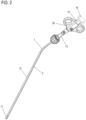
- FIGS. 1 and 2 each show a perspective view of a first embodiment of a working channel element 1 according to the invention. More specifically, Fig.1 a state in which the working channel element 1 according to the invention is installed in an endoscope, and Fig.2 shows the working channel element 1 separately from the endoscope.
- the endoscope 100 has an elongated endoscope body.
- This endoscope 100 is designed, for example, as a flexible endoscope for the gastrointestinal tract.
- the endoscope has an operating part A and an insertion section B
- the operating part A is located on the proximal side and the insertion section B is located on the distal side of the endoscope 100.
- the operating part A has a working channel inlet 101 and an adjusting knob 103 for bending an endoscope bending section at the distal end of the insertion section B of the endoscope.
- the working channel inlet 101 is provided with a connection element 104, which can be designed in the form of a conventional Luer-lock connection.
- the operating part A is provided with a handle section 105 by which the operator holds the endoscope 100.
- the control part A is connected via cable 106 to a video processor, a light source device and a display device and the like.
- the insertion section B is a long tube-like member. The proximal end of the insertion section is connected to the operating part A.
- the insertion section B has a flexible section and the endoscope bending section 107 in this order as viewed from the operating part A.
- the flexible section is elastic.
- the endoscope bending section 107 is bent in response to an operation of the adjusting knob 103.
- a rigid end piece section is formed at the distal end of the endoscope bending section 107.
- the rigid end piece section forms the so-called endoscope head 108.
- An ultrasonic sensor 102 is arranged at the distal end of the endoscope head 108.
- the operating part A On the distal side of the handle section 105, the operating part A has an angled access.
- a working channel is provided in the endoscope 1.
- the working channel starts at the working channel inlet 101 formed on the proximal side of the angled access, passes through the angled access, opens into the operating part A and passes through the operating part A in the distal direction, passes through the insertion section B and opens at the endoscope head 108 so that it is directed in the distal direction.
- the working channel element 1 according to the invention described below can be inserted into this working channel of the endoscope 1.
- the working channel element 1 is in Figure 2 shown separately from the endoscope.
- the working channel element 1 has a flexible hose element 2.
- the flexible hose element 2 is made of an elastic material and preferably consists of plastic or rubber.
- the flexible hose element 2 is designed as a cylinder-like tube with an inner circumference and an outer circumference.
- the outer circumference of the flexible hose element 2 is smaller than the working channel of the endoscope 1 described above.
- the inner circumference of the flexible hose element 2 is of such a size that micro tools for examining, for example, the esophagus or also the duodenum, the bile duct, the gall bladder, the pancreatic duct, the pancreas, etc. can be guided through it.
- the flexible hose element 2 is designed as a main hose 12 on the proximal side.
- the working channel element 1 On the distal side of the hose element 2, the working channel element 1 has a bending section 11 which connects distally to the main hose 12, see also Fig. 12 .
- the bending section 11 is a bendable section of the hose element 2. At its proximal end, the bending section 11 has a proximal ring element to which the distal end of the main hose 12 is connected. At the distal end, the bending section 11 has a distal ring element. Between the proximal ring element and the distal ring element, the bending section 11 can be bent (bent) via pull wires (cables) described below.
- Pull wires are arranged between the inner circumference and the outer circumference of the hose element 2 in the working channel element 1, extending in the longitudinal direction.
- at least one pull wire is used.
- one pull wire is sufficient.
- several pull wires can be used.
- the pull wires of the working channel element 1 run in pull wire channels or pull wire areas between the inner circumference and the outer circumference of the tube element 2. These pull wire channels or pull wire areas are sealed from the environment at least on the distal side of the working channel element 1.
- a pull wire is provided in the working channel element 1 according to the invention.
- the pull wire On the distal side of the hose element 2, i.e. in the bending section 11, the pull wire is guided through the proximal ring element and the hose piece of the bending section 11 to the distal ring element and anchored to the distal ring element.
- the distal ring element forms the distal anchoring point of the pull wire.
- the pull wire is thus arranged along the axial direction of the working channel element 1 and anchored to the distal side of the bending section 11 and can be actuated on the proximal side of the working channel element 1 by a control unit. This means that when the pull wire is pulled, the anchoring point on the distal side of the bending section 11 of the working channel element 1 is pulled in the proximal direction, whereby the bending section 11 is bent.
- the lateral orientation of the bending section 11 can be changed by pulling the pull wire in a known manner.
- the bending section 11 changes the orientation angle of the micro tools that are pushed through the inner channel 13 of the tube element 2.
- the orientation of the micro tools can thus be changed to the desired lateral direction by changing the angle of the bending section 11 relative to the endoscope head 108.
- the micro tools then protrude laterally from the endoscope head 108 in the selected angular position in order to be pushed into a bile duct, for example.
- the distal end of the working channel element 1 is located proximal to the ultrasonic sensor 102.
- the proximal side of the working channel element 1 is in Figure 3 shown.
- the working channel element 1 On the proximal side of the hose element 2, the working channel element 1 has a transition element 13.
- the transition element 13 is designed as a hollow element with a diameter that increases in the proximal direction.
- a rod element 14 is provided proximal to the transition element 13.
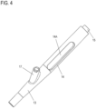
- the rod element 14 is a hollow cylinder provided with a bottom, which has a continuous lateral slot 14A extending in the longitudinal direction of the rod element 14, as shown in Fig.4 is shown.
- the base of the rod element 14 points in the proximal direction.
- the opening of the rod element 14 opposite the base is connected to the transition element 13.
- the proximal end of the tube element 2, the transition element 13 and the rod element 14 are arranged on the same axis.
- a nose 15 is arranged on the bottom of the rod element 14, which points in the proximal direction.
- a plate element 16 is placed on the nose 15, the proximal surface of which serves as a thumb actuation surface, see Figure 5 .
- the respective connection between the hose element 2 and transition element 13, transition element 13 and rod element 14, plate element 16 and nose 15 can be created by gluing, by laser beam treatment, by soldering or by another suitable method.
- the plate element 16 can also be pushed or pressed onto the nose 15.
- a tube-like instrument access 17 extends laterally from the transition element 13, penetrating the outer wall of the transition element 13, through which instruments, micro tools, etc. can be pushed in the distal direction into the inner channel of the hose element 2, i.e. the working channel element 1.
- the instrument access 17 can be attached to the transition element 13 by laser beam treatment, by soldering or by another suitable method.
- the pull wire (alternatively the pull wires) penetrates the inner circumference of the working channel element 1 and runs to the control unit 20 described below.
- the location at which the pull wire penetrates the inner circumference of the working channel element 1 can be located proximal to the instrument access 17.
- a slider 20 is arranged on the rod element 14 as a control unit so as to be displaceable in the longitudinal direction of the rod element 14.
- the slider 20 is described below with reference to Figure 6 explained in more detail.
- the slider 20 has a tube section 20A with an inner diameter that is slightly larger than the outer diameter of the rod element 14. This allows the slider 20 to be displaced on the rod element 14.
- the slide 20 has a hole 20B in the region of the pipe section 20A, which extends perpendicular to the longitudinal axis of the pipe section 20A and points in the radial, i.e. lateral, direction.
- two side wings 20C protrude radially from the pipe section 20A in a flange-like manner.
- the two side wings 20C extend in mutually opposite directions from the pipe section 20A.
- the above-mentioned hole 20B is arranged offset at an angle of 90 degrees to the respective side wing 20C, as shown in Fig.6 is shown.
- Each side wing 20C has an opening 20D of a size to allow the operator's finger to pass through.
- the pull wire is anchored to the slider 20.
- the slider 20 thus forms the proximal anchoring point of the pull wire(s).
- the pull wire is anchored, for example, to the inner circumference of the slider 20.
- a pivot pin 30 is inserted into the hole 20B of the pipe section 20A of the slide 20 as a locking device.
- the pivot pin 30 is designed as a cylindrical pin flattened on one side, which forms the shape of a letter D in cross section. On the non-flattened side, the pivot pin 30 has an outer diameter that is larger than the gap width of the slot 14A. In the cross section of the pivot pin 30, the dimension from the flattened side to the opposite outer circumference is less than the gap width of the slot 14A. In other words, the pivot pin 30 has a first radial dimension that is larger than the gap width of the slot 14A and a second radial dimension that is smaller than the gap width of the slot 14A.
- the pivot pin 30 projects into the slot 14A.
- the pivot pin 30 has a recess 30A on the outward-facing side into which a tool can be positively inserted in order to rotate the pivot pin 30.
- the pivot pin 30 When the slider 20 is displaced on and relative to the rod element 14, the pivot pin 30 has a relative position to the slider 20 in which the pivot pin 30 is guided in the slot 14A with its second radial dimension, which is smaller than the gap width of the slot 14A.
- the working channel element 1 when placed in the endoscope, can be mounted on the endoscope by means of a mounting device 50.
- the endoscope 100 For this purpose, the device itself has a conventional Luer-lock connection on its connection element 104, into which the mounting device 50 of the working channel element 1 engages.
- Fig.7 shows the elements of the mounting device 50. More precisely, the mounting device 50 consists of a Luer-lock counterpart 51 that fits the Luer-lock connection of the endoscope 100 and a screw cap 52 placed on the Luer-lock counterpart 51.
- the Luer-lock counterpart 51 is located on the outer circumference of the working channel element 1 approximately in the area where the hose 2 (main hose 12) and the transition element 13 meet.
- the Luer-lock counterpart 51 is firmly located on the outer circumference of the working channel element 1.
- the Luer-lock counterpart 51 is locked to the Luer-lock connection of the endoscope 100 using a screw cap 52.
- Luer-lock system is a standardized connection system for hose systems in the medical field, it does not need to be explained in more detail here.
- the working channel element 1 is inserted into the endoscope 100 such that the radial side of the bending section 11, on which the distal anchoring point of the pull wire is arranged, is located on the radial side opposite to the ultrasound head 102.
- a working channel element 1 separate from the endoscope 100 is thus introduced into the working channel 101 of the endoscope 100. More specifically, the working channel element 1 is inserted into the working channel 101 from the proximal side of the working channel 101 with the distal side of the working channel element 1 first.
- the working channel element 1 After the working channel element 1 has been completely inserted into the working channel 101 of the endoscope 100, the working channel element 1 is mounted on the endoscope 100 by the mounting device 50 (Luer lock). In this mounting position, the radial side of the bending section 11, in which the pull wire is anchored, faces the radial side opposite the ultrasound head 102.
- the endoscope 100 equipped with the working channel element 1 is thus ready for use.
- the endoscope 100 equipped with the working channel element 1 is introduced into the patient to the desired application site (e.g. the bile duct).
- the operator can now bend the bending section 11 at the distal end of the working channel element 1 to a desired position by moving the slider 20 in the proximal direction.
- the desired angled position of the bending section 11 is reached (e.g. opposite the bile duct)
- the position of the slider 20 is locked by the locking device 30.
- an instrument microwave tool
- the required activity can be carried out with the instrument.
- the instrument is returned.
- the slider 20 is now released. By moving the slider 20 in the distal direction, the tension on the pull wire is relaxed, which stretches the bending section 11.
- the endoscope can be removed from the patient.
- the mounting device 50 is released and the working channel element 1 is pulled out of the endoscope 100 and disposed of.
- the working channel element 1 is only temporarily arranged in the endoscope 100. After the one-time use of the working channel element 1, it is removed from the endoscope 100 and disposed of. The endoscope 100, on the other hand, is sent for reprocessing.
- the working channel element 1 can perform the function of a conventional Albarran lever in endoscopes, which adjusts the angular position of instruments, as well as a horizontal fine adjustment of the desired target position of the instrument.
- the controllable end piece is connected to a working channel, which itself is not firmly connected to the endoscope and can be removed from the endoscope.
- the endoscope is a flexible endoscope with an Albarran lever.
- a working channel element 1 according to the invention can be inserted into the endoscope.
- the working channel element 1 corresponds to the working channel element 1 of the first embodiment.
- the endoscope has a control mechanism (not shown) (e.g. a joystick) for actuating an Albarran lever (not shown) arranged at the distal end of the insertion section B.
- a control mechanism e.g. a joystick
- an Albarran lever (not shown) arranged at the distal end of the insertion section B.
- the working channel element 1 of the second embodiment according to the invention protrudes from the distal end of the endoscope head on the distal side after it has been introduced into the endoscope and mounted on the endoscope by means of a mounting device. More precisely, the bending section 11 of the working channel element protrudes 1 from the distal end of the endoscope head.
- the remaining structure corresponds to the structure of the first embodiment.
- the bending of the inserted instruments on the distal side can be accomplished not only by the bending section 11 of the working channel element 1.
- the Albarran lever can take over the main bending of the distal end piece of the working channel element 1.
- the operator can carry out a fine adjustment by a separate bending of the bending section 11 of the working channel element 1.
- At least a part of the bending section 11 is arranged distally from the Albarran lever of the endoscope when the working channel element 1 is installed in the endoscope.
- the endoscope 1 is a flexible endoscope and the working channel element 1 has the bending section 11 which can be bent by the control unit 20.
- the endoscope is also a flexible endoscope.
- the endoscope has a working channel element 1 without a bending section 11 and without a control unit 20.
- a working channel element 1 is therefore introduced into the endoscope, which is not itself controlled.
- This design also has the advantageous effect that after use the working channel element 1 according to the invention can be removed from the endoscope can be pulled out and disposed of. The endoscope is then subjected to the cleaning process.
- the working channel element 1 is pulled out of the endoscope 100 in the proximal direction.
- the invention is not limited to this.
- the working channel element 1 is severed (e.g. cut) in the region of the proximal end of the main tube 12 or in the region of the transition element 13. Only the control unit of the working channel element 1 is removed in the proximal direction. The contaminated part of the working channel element 1, i.e. the bending section 11 and a distal part of the main tube 12, is pulled out of the endoscope 100 in the distal direction.
- a predetermined breaking point is provided in the area of the proximal end of the main tube 12 or in the area of the transition element 13.
- the working channel element 1 can be bent and broken at the predetermined breaking point. This simplifies the separation of the working channel element 1 between the control unit of the working channel element 1, which is to be removed in the proximal direction, and the contaminated part of the working channel element 1, which is to be removed from the endoscope 100 in the distal direction.
- control unit of the working channel element 1 can be reused in this sub-variant.
- Figure 8 shows a working channel element 1 of the fifth embodiment in a situation in which it is being attached to an endoscope 100.
- Figure 9 shows the working channel element 1 of the fifth embodiment in a situation in which the assembly of the working channel element 1 on the endoscope 100 is completed.
- the working channel element 1 of the fifth embodiment has a control unit 20' which is modified compared to the control unit 20 of the first embodiment.
- the control unit is designed as a lever 20'.
- the lever 20' has a base area to which the control wires are mounted in such a way that they are tensioned when the lever 20' is pivoted.
- the proximal region of the working channel element 1 of the fifth embodiment is integrated in a housing part 60, from whose outer surface the lever 20' extends.
- the housing part 60 has a housing piece 61 which has an area which is adapted to the outer contour of a handle section of the endoscope 100 so that it can be clipped onto the handle section of the endoscope 100.
- the housing piece 61 has a closure element 62 at a suitable location, by means of which the housing piece 61 is secured to the endoscope 100, see Fig.9 .
- the closure element is not limited to a closure element 62 as in Fig.9 limited. Any type and shape of closure element can be used.
- the proximal area of the working channel element 1 is integrated inside the housing piece 61.
- the lever 20' can have a shaft (not shown).
- the lever 20' can pivot about this shaft.
- This shaft is inserted through a section of the working channel element 1 that corresponds to the rod element 14 of the first embodiment.
- the pull wires are wound around the shaft inside this section of the working channel element 1. The pull wires can thus be tensioned when the lever 20' is pivoted.
- the working channel element 1 can be easily and quickly attached to the handle area of the endoscope 100 after being inserted into the working channel of the endoscope 100.
- both the control unit 103 of the endoscope 100 and the lever 20' are easily accessible and operable.
- Such an endoscope as used in the fifth embodiment can be designed in such a way that its distal end can only be operated by means of the clipped-on working channel element 1. Thus, such an endoscope cannot be used without the clipped-on working channel element 1.
- Figure 10 shows a working channel element 1 of the sixth embodiment in a situation in which it is being attached to an endoscope 100.
- Figure 11 shows the working channel element 1 of the sixth embodiment in a situation in which the assembly of the working channel element 1 on the endoscope 100 is completed.
- the working channel element 1 of the sixth embodiment has a control unit modified from the control unit 20 of the first embodiment, which is designed as a lever 20' similar to the fifth embodiment.
- the proximal region of the working channel element 1 of the sixth embodiment is mounted and secured to the endoscope 100 via Luer-lock as in the first embodiment.
- the working channel element 1 can also be easily and quickly attached to the handle area of the endoscope 100 using a Luer lock after being inserted into the working channel of the endoscope 100.
- both the control unit 103 of the endoscope 100 and the lever 20' are easily accessible and operable.
- Such an endoscope as shown in the sixth embodiment can be designed in such a way that its distal end can also be operated without a working channel element 1. Thus, such an endoscope can also be used without a mounted working channel element 1.
- the present invention can preferably be applied to a duodenoscope as described, but is not limited thereto.
- the present invention can also be applied to a gastroscope, a colonoscope or a similar endoscope.
- the principle of the invention can also be applied to any other type of endoscope.
- the endoscope is a flexible endoscope.
- the endoscope can also be designed as a rigid endoscope in which the working channel element 1 according to the invention can be used.
- the ultrasonic sensor 102 is arranged at the distal end of the endoscope head 108.
- the ultrasonic sensor 102 can also be omitted.
- two traction cables can be provided in the working channel element 1, which are anchored relatively close to one another on one side of the circumference at the distal end of the working channel element 1.
- the traction wires can each be arranged so that they are not spaced apart by 180° from one another, i.e. the traction wires are arranged close to one another along the circumference of the hose element 2 on one side of the circumference.
- the traction wires are guided through the proximal ring element and the hose piece of the bending section 11 to the distal ring element and anchored to the distal ring element.
- the distal ring element forms the distal anchoring point of the traction wires.
- two pull wires can be arranged close to each other along the circumference at the distal end (short distance) and spaced 180° apart from each other on the proximal side on the slider 20 (equal distance). The distance between the individual pull wires measured in the circumferential direction is therefore changed along the entire tube element 2.
- the bending section 11 on the lateral side, on which the two pull wires are anchored distally is bent outwards.
- three or four or more pull wires can be provided in the working channel element 1 according to the invention. If three or more pull wires are used, they can also be anchored relatively close to one another on one side of the circumference at the distal end of the working channel element 1.
- the three or more pull wires can alternatively be anchored to the circumference at the distal end of the working channel element 1 be that two (of three), three (of four), etc. of the pull wires are relatively close to one another on one side of the circumference, and one pull wire is anchored on the opposite circumferential side.
- the slider 20 is provided so as to be rotatable about the rod element 14 (about its own axis). By pulling and rotating the slider 20 relative to the rod element 14, the respective pull wires can be individually tensioned differently.
- control unit 20 is not limited to the slider or the lever.
- a handwheel for example, can be used as the control unit 20. Any mechanism that can tension pull wires individually or as a group can be used.
- the control unit 20 does not have to consist of just one mechanism. Two or more mechanisms can also be used, each assigned to one or a group of pull wires. This can improve the control accuracy even further.
- the slider 20 of the first embodiment can be separated in the axial direction in the axis area into two slider elements, each forming a side wing 20C and overlapping each other in the axis area.
- each side wing 20C has a partial tube section 20A, one of which overlaps the other.
- At least one pull wire is anchored in both side wings 20C, and the side wings 20C can be moved relative to each other along the rod element 14.
- a corresponding axially extending slot is provided in both side wings 20C on the partial tube section 20A. In this alternative, the pull wires can be controlled separately.
- a pull wire is described for controlling the bending of the distal end of the working channel element 1.
- the term “pull wire” does not only mean a wire in the general sense.
- a pull cable or a Bowden cable construction can be used as the "pull wire”.
- the material of the "pull wire” is not subject to any restrictions.
- the "pull wire” only has to be able to transmit a force from any control mechanism to the distal end of the working channel element 1 in order to control the direction and/or the angle and/or the extent of the bending of the distal end of the working channel element 1.
- a working channel element not according to the invention can also be designed without a bending section 11. In this alternative, no control unit is required to control the bending. Such a working channel element also offers the advantage that the actual working channel of the endoscope, into which the working channel element is inserted, is not contaminated during use. Cross-contamination can also be prevented in this alternative, since a separate working channel is used for each patient.
Landscapes
- Health & Medical Sciences (AREA)
- Life Sciences & Earth Sciences (AREA)
- Surgery (AREA)
- Nuclear Medicine, Radiotherapy & Molecular Imaging (AREA)
- Biomedical Technology (AREA)
- Veterinary Medicine (AREA)
- Pathology (AREA)
- Radiology & Medical Imaging (AREA)
- Biophysics (AREA)
- Engineering & Computer Science (AREA)
- Physics & Mathematics (AREA)
- Heart & Thoracic Surgery (AREA)
- Medical Informatics (AREA)
- Molecular Biology (AREA)
- Animal Behavior & Ethology (AREA)
- General Health & Medical Sciences (AREA)
- Public Health (AREA)
- Optics & Photonics (AREA)
- Endoscopes (AREA)
Description
- Die vorliegende Erfindung bezieht sich auf ein Arbeitskanalelement für ein Endoskop, und Endoskop mit diesem Arbeitskanalelement. Ferner bezieht sich die vorliegende Erfindung auf ein Verfahren zur Anwendung eines Arbeitskanals in einem Endoskop.
- Ein solches Endoskop kann beispielsweise ein Duodenoskop sein, also ein Endoskop zur Untersuchung z.B. der Speiseröhre oder auch des Duodenums, des Gallengangs, der Galle, des Bauchspeicheldrüsengangs, der Bauchspeicheldrüse etc. Mit Hilfe des Duodenoskops ist es möglich, durch die Speiseröhre, den Magen und den Magenausgang in das Duodenum zu gelangen.
- Das Duodenoskop hat eine zur Seite gerichtete (laterale) Optik (Beleuchtungseinrichtung und Kamera). Dies kann das Einführen und Vorschieben durch die Speiseröhre zu erschweren, da keine "nach vorn" erfolgende Betrachtung ohne weiteres möglich ist. Lediglich im Magen oder im Duodenum besteht ausreichend Raum, um das distale Ende des Duodenoskops um etwa 90° abzuwinkeln, um so nach vorn schauen zu können.
- Das Duodenoskop hat außerdem am Ausgang des Arbeitskanals einen Albarranhebel, der durch Verschwenken eine gezielte Umlenkung der Werkzeuge ermöglicht, die durch den Arbeitskanal geschoben werden. Ein solcher Albarranhebel hat in der Regel eine komplexe Geometrie, die schwer zu reinigen ist.
- Bei einigen Duodenoskopen kann der Albarranhebel als Einmalverwendungselement gestaltet werden, um die Möglichkeit des Anhaftens von Keimen am wiederverwendbaren Endoskop noch besser zu vermeiden.
- Selbst bei diesen Duodenoskopen können Keime sich im Arbeitskanal verfangen.
- Nach der Anwendung des Duodenoskops wird dieses einer Aufbereitung unterzogen. Diese muss zuverlässig die Übertragung sämtlicher Mikroorganismen wie Bakterien, Viren, Pilze, Würmer aber auch Sporen ausschließen. Bei der Aufbereitung wird zunächst das Duodenoskop inklusive Arbeitskanal manuell gereinigt, um organisches Material oder chemische Rückstände rückstandsfrei zu entfernen. Nach der Reinigung erfolgt eine maschinelle Desinfektion oder Sterilisation.
- Die
US 2015/057537 A1 offenbart ein Endoskop, in das ein Schlauchelement als ein Arbeitskanalelement eingeführt wird. Dieses Arbeitskanalelement hat die Merkmale des Oberbegriffs von Anspruch 1. - Die
US 2006/149129 A1 zeigt ein Endoskop, in das ein Betrachtungsrohr eingeführt wird. - Die
US 2012/0265132 A1 zeigt einen Katheter, der ein Multi-lumen-Rohr aufweist. In das Multi-lumen-Rohr können Elemente eingeführt werden können. - Die
US 2016/0227988 A1 offenbart ein Endoskop, in das beispielweise eine Biopsiezange eingeführt wird. - Die
JP 6 017741 B1 - Die
JP 3 595489 B2 -
US 2011/213300 A1 offenbart ein kleineres Endoskop, das in ein größeres Endoskop eingeführt wird. Der Griffabschnitt des kleineren Endoskops ist am Griffabschnitt des größeren Endoskops befestigt. -
US 2006/252993 A1 offenbart eine Befestigung einer Hilfsvorrichtung an einem Endoskop, wobei eine Montagevorrichtung um den Außenumfang eines Zugangs am Endoskop angeordnet ist. - Es ist die Aufgabe der vorliegenden Erfindung, ein verbessertes Arbeitskanalelement und ein verbessertes Endoskop zu schaffen, bei dem das Weitergeben von Keimen noch besser vermieden wird.
- Diese Aufgabe ist durch ein Arbeitskanalelement mit den Merkmalen von Anspruch 1 gelöst. Ein Endoskop mit dem Arbeitskanalelement ist in Anspruch 4 aufgezeigt. Ein Verfahren zur Anwendung eines Arbeitskanals in einem Endoskop ist in Anspruch 5 aufgezeigt.
- Vorteilhafte Weiterbildungen sind Gegenstand der abhängigen Ansprüche.
- Ein erfindungsgemäßes Arbeitskanalelement laut Anspruch 1 weist eine Rohrform mit einem Innenumfang und einem Außenumfang auf, wobei durch die Rohrform ein Instrument schiebbar ist. Das Arbeitskanalelement ist daran angepasst, mit seiner distalen Seite voran in einen Arbeitskanal eines Endoskops vorübergehend eingeführt zu werden. Das Arbeitskanalelement weist eine Außenwand auf, die lateral von einem Instrumentenzugang durchdrungen ist. Durch den Instrumentenzugang können Instrumente in einen Innenkanal des Arbeitskanalelements geschoben werden.
- Das Arbeitskanalelement hat ein Außenmaß, das ein Einführen in einen Arbeitskanal eines Endoskops erlaubt. Das Arbeitskanalelement ist an die Form des Arbeitskanals des Endoskops angepasst. Die Form des Arbeitskanalelements ist vorzugsweise eine runde Form. Das Außenmaß (z.B. Außendurchmesser) des Arbeitskanalelements ist somit geringfügig kleiner als das Innenmaß (z.B. Innendurchmesser) des Arbeitskanals des Endoskops.
- Somit kann in der Erfindung ein Endoskop mit einem nicht fest verbundenen, entfernbaren Arbeitskanal versehen werden.
- Dadurch ergibt sich eine vereinfachte Reinigung des Endoskops, da für jeden Patienten ein eigener Arbeitskanal verwendet werden kann, der entsorgt werden kann. Gereinigt braucht nur das Endoskop werden, in dessen eigenen Arbeitskanal lediglich das erfindungsgemäße Arbeitskanalelement eingeführt worden war.
- Das Arbeitskanalelement weist an der distalen Seite einen Abwinkelungsabschnitt auf. Somit kann das Arbeitskanalelement selbst die Aufgabe des Auslenkens eines eingeschobenen Instrumentes übernehmen, die z.B. ein bisheriger Albarranhebel inne hatte. Die bisherige komplexe Geometrie eines Albarranhebels am distalen Ende des Endoskops kann dabei entfallen. Somit wird auch das Endoskop selbst leichter und besser reinigbar. Kreuzkontaminationen von Patient zu Patient können noch besser verhindert werden.
- Das Arbeitskanalelement weist an der proximalen Seite eine Steuereinheit zum Steuern des Abwinkelns des Abwinkelungsabschnittes auf. Die Steuereinheit ist so aufgebaut, dass sie im Arbeitskanalelement zwischen Innenumfang und Außenumfang geführte am Abwinkelungsabschnitt verankerte Steuerdrähte spannt, um das Abwinkeln des Abwinkelungsabschnittes zu steuern. Dadurch kann das Auslenken eines eingeschobenen Instrumentes vorteilhaft und einfach bewerkstelligt werden.
- Die Steuereinheit ist als Schieber aufgebaut ist, in dem das proximale Ende der Steuerdrähte verankert ist.
- Die Steuereinheit kann eine Vielzahl an separaten Steuerelementen aufweisen, wobei jedem separaten Steuerelement mindestens einer der Steuerdrähte zugeordnet ist.
- Das Arbeitskanalelement weist der proximalen Seite eine Feststelleinrichtung zum Fixieren einer abgewinkelten Stellung des distalen Abwinkelungsabschnittes auf. Durch die Feststelleinrichtung (z.B. ein Bremsmechanismus) kann der Arzt dann die für ihn ideale ausgelenkte Position fixieren und Therapieinstrumente durch den Arbeitskanal an die gewünschte Position im Gewebe bringen.
- Das Arbeitskanalelement kann an der proximalen Seite eine Montageeinrichtung aufweisen, durch die das Arbeitskanalelement an einem Endoskop montiert werden kann. Dadurch kann das erfindungsgemäße Arbeitskanalelement schnell und stabil am Endoskop auf eine Weise montiert werden, die dem Bediener (Arzt) vertraut ist. Die Montageeinrichtung des erfindungsgemäßen Arbeitskanalelements ist vorzugsweise distal einer Steuereinheit des Arbeitskanalelements vorgesehen.
- Ein Endoskop kann mit einem solchen Arbeitskanalelement ausgestattet sein. Die Steuereinheit zum Steuern des Abwinkelns des Abwinkelungsabschnittes kann nahe zu einem Griffabschnitt des Endoskops so anordenbar sein, dass der Bedienende bequem sowohl den Steuerabschnitt des Endoskops als auch die Steuereinheit zum Steuern des Abwinkelns des Abwinkelungsabschnittes (idealerweise mit einer Hand) erreichen und bedienen kann. Das Endoskop kann ein beliebiges Endoskop sein, welches einen eigenen Arbeitskanal besitzt.
- In einem erfindungsgemäßen Verfahren zur Anwendung eines Arbeitskanals in einem Endoskop wird ein separates Arbeitskanalelement mit seiner distalen Seite voran in einen Arbeitskanal eines Endoskops vorübergehend eingeführt.
- Das Verfahren kann des Weiteren die folgenden Schritte aufweisen: Einführen des Arbeitskanalelements in das Endoskop; und Abwinkeln eines distalen Endes des Arbeitskanalelementes zur gewünschten Position.
- Nach der einmaligen Anwendung des Arbeitskanalelementes kann das Arbeitskanalelement aus dem Endoskop herausgezogen und entsorgt werden.
- Nach der einmaligen Anwendung des Arbeitskanalelementes kann das Arbeitskanalelement aus dem Endoskop an der distalen Seite des Endoskops herausgezogen und entsorgt werden. Das benutzte Arbeitskanalelement verlässt das Endoskop an der distalen Seite des Endoskops. Somit werden Keime nicht in die proximale Richtung im Endoskop geleitet. Dadurch kann ein noch besserer Schutz vor Kontamination geschaffen werden.
- Die vorstehend erläuterten Aspekte der vorliegenden Erfindung können geeignet kombiniert werden.
-
-
Fig. 1 zeigt eine perspektivische Ansicht eines erfindungsgemäßen Arbeitskanalelementes eines ersten Ausführungsbeispiels in einem im Endoskop eingebauten Zustand. -
Fig. 2 zeigt eine perspektivische Ansicht des erfindungsgemäßen Arbeitskanalelementes des ersten Ausführungsbeispiels separat vom Endoskop, wobei die Lage eines Ultraschallsensors angedeutet ist. -
Fig. 3 zeigt eine perspektivische Ansicht einer Steuereinheit des erfindungsgemäßen Arbeitskanalelementes des ersten Ausführungsbeispiels. -
Fig. 4 zeigt eine perspektivische Ansicht eines proximalen Endabschnittes des erfindungsgemäßen Arbeitskanalelementes des ersten Ausführungsbeispiels. -
Fig. 5 zeigt eine weitere perspektivische Ansicht des proximalen Endabschnittes des erfindungsgemäßen Arbeitskanalelementes des ersten Ausführungsbeispiels. -
Fig. 6 zeigt eine perspektivische Ansicht eines Steuerelements der Steuereinheit des erfindungsgemäßen Arbeitskanalelementes des ersten Ausführungsbeispiels. -
Fig. 7 zeigt eine perspektivische Ansicht von Elementen einer Montageeinrichtung des erfindungsgemäßen Arbeitskanalelementes des ersten Ausführungsbeispiels. -
Fig. 8 zeigt eine perspektivische Ansicht eines nicht erfindungsgemäßen Arbeitskanalelementes eines fünften Ausführungsbeispiels. -
Fig. 9 zeigt eine perspektivische Ansicht des ersten Anwendungsbeispiels des nicht erfindungsgemäßen Arbeitskanalelementes des fünften Ausführungsbeispiels im am Endoskop angebauten Zustand. -
Fig. 10 zeigt eine perspektivische Ansicht eines nicht erfindungsgemäßen Arbeitskanalelementes eines sechsten Ausführungsbeispiels. -
Fig. 11 zeigt eine perspektivische Ansicht des zweiten Anwendungsbeispiels des nicht erfindungsgemäßen Arbeitskanalelementes des sechsten Ausführungsbeispiels im am Endoskop angebauten Zustand. -
Fig. 12 zeigt eine perspektivische Ansicht des distalen Endabschnittes des erfindungsgemäßen Arbeitskanalelementes des ersten Ausführungsbeispiels. Nachstehend ist die vorliegende Erfindung detailliert unter Bezugnahme auf die Zeichnungen anhand von Ausführungsbeispielen beschrieben. - Zunächst ist unter Bezugnahme auf die
Figuren 1 bis 7 ein erstes Ausführungsbeispiel der vorliegenden Erfindung beschrieben. - Die
Figuren 1 und2 zeigen jeweils eine perspektivische Ansicht eines ersten Ausführungsbeispiels eines erfindungsgemäßen Arbeitskanalelementes 1. Genauer gesagt zeigtFig. 1 einen Zustand, bei dem das erfindungsgemäße Arbeitskanalelement 1 in einem Endoskop eingebaut ist, undFig. 2 zeigt das Arbeitskanalelement 1 separat vom Endoskop. - Zunächst ist unter Bezugnahme auf
Figur 1 ein Endoskop 100 kurz beschrieben, bei dem das erfindungsgemäße Arbeitskanalelement 1 angewendet werden kann. Das Endoskop 100 hat einen länglichen Endoskopkörper. - Dieses Endoskop 100 ist z. B. als flexibles Endoskop für den Magen-Darm-Trakt ausgebildet. Das Endoskop weist ein Bedienteil A und einen Einführabschnitt B auf. Der Bedienteil A befindet sich an der proximalen Seite und der Einführabschnitt B befindet sich an der distalen Seite des Endoskops 100. Der Bedienteil A weist einen Arbeitskanaleinlass 101 und einen Stellknopf 103 für das Biegen eines Endoskop-Abwinklungsabschnittes am distalen Ende des Einführabschnitts B des Endoskops auf. Der Arbeitskanaleinlass 101 ist mit einem Anschlusselement 104 versehen, das in der Form eines üblichen Luer-lock-Anschlusses ausgebildet sein kann. Ferner ist der Bedienteil A mit einem Griffabschnitt 105 versehen, an dem der Bedienende das Endoskop 100 hält.
- Der Bedienteil A ist per Kabel 106 ist mit einem Videoprozessor, einer Lichtquellenvorrichtung und einer Anzeigevorrichtung und dergleichen verbunden.
- Der Einführabschnitt B ist ein langes schlauchartiges Element. Das proximale Ende des Einführabschnitts ist mit dem Bedienteil A verbunden. Der Einführabschnitt B weist einen flexiblen Abschnitt und den Endoskop-Abwinklungsabschnitt 107 in dieser Reihenfolge vom Bedienteil A aus gesehen auf. Der flexible Abschnitt ist elastisch. Der Endoskop-Abwinklungsabschnitt 107 wird im Ansprechen auf eine Betätigung des Stellknopfes 103 abgewinkelt. Am distalen Ende des Endoskop-Abwinklungsabschnittes 107 ist ein starrer Endstückabschnitt ausgebildet. Der starre Endstückabschnitt bildet den sogenannten Endoskopkopf 108. Ein Ultraschallsensor 102 ist am distalen Ende des Endoskopkopfes 108 angeordnet.
- An der distalen Seite des Griffabschnittes 105 besitzt der Bedienteil A einen abgewinkelten Zugang.
- Im Endoskop 1 ist ein Arbeitskanal vorgesehen. Der Arbeitskanal beginnt am Arbeitskanaleinlass 101, der an der proximalen Seite des abgewinkelten Zugangs ausgebildet ist, durchläuft den abgewinkelten Zugang, mündet in den Bedienteil A und durchläuft den Bedienteil A in distaler Richtung, durchläuft den Einführabschnitt B und mündet am Endoskopkopf 108 so, dass er in die distale Richtung gerichtet ist.
- In diesen Arbeitskanal des Endoskops 1 ist das nachstehend beschriebene erfindungsgemäße Arbeitskanalelement 1 einführbar.
- Das Arbeitskanalelement 1 ist in
Figur 2 separat vom Endoskop gezeigt. - Das Arbeitskanalelement 1 weist ein flexibles Schlauchelement 2 auf. Das flexible Schlauchelement 2 ist aus einem elastischem Material hergestellt und besteht vorzugsweise aus Kunststoff oder Gummi. Das flexible Schlauchelement 2 ist als ein zylinderartiges Rohr mit einem Innenumfang und einem Außenumfang ausgebildet. Der Außenumfang des flexiblen Schlauchelements 2 ist kleiner als der vorstehend beschriebene Arbeitskanal des Endoskops 1. Der Innenumfang des flexiblen Schlauchelements 2 hat eine derartige Größe, dass Mikrowerkzeuge zur Untersuchung z.B. der Speiseröhre oder auch des Duodenums, des Gallengangs, der Galle, des Bauchspeicheldrüsengangs, der Bauchspeicheldrüse etc. hindurchgeführt werden können.
- Das flexible Schlauchelement 2 ist an der proximalen Seite als Hauptschlauch 12 ausgebildet. An der distalen Seite des Schlauchelements 2 hat das Arbeitskanalelement 1 einen Abwinkelungsabschnitt 11, der sich distal an den Hauptschlauch 12 anschließt, siehe auch
Fig. 12 . - Der Abwinkelungsabschnitt 11 ist ein biegbarer Abschnitt des Schlauchelements 2. An seinem proximalen Ende besitzt der Abwinkelungsabschnitt 11 ein proximales Ringelement, an dem das distale Ende des Hauptschlauches 12 angeschlossen ist. An dem distalen Ende besitzt der Abwinkelungsabschnitt 11 ein distales Ringelement. Zwischen dem proximales Ringelement und dem distalen Ringelement ist der Abwinkelungsabschnitt 11 über nachstehend beschriebene Zugdrähte (Seilzüge) biegbar (abwinkelbar).
- In den Zeichnungen nicht gezeigte Zugdrähte (Seilzüge) sind zwischen dem Innenumfang und dem Außenumfang des Schlauchelements 2 im Arbeitskanalelement 1 sich in der Längsrichtung erstreckend angeordnet. Im Ausführungsbeispiel wird zumindest ein Zugdraht angewendet. Um die Funktion des Abwinkelungsabschnittes 11 zu gewährleisten, ist ein Zugdraht ausreichend. Um eine feinere (genauere) Steuerung der Abwinklung des Abwinkelungsabschnittes 11 zu erzielen, können mehrere Zugdrähte angewendet werden.
- Die Zugdrähte des Arbeitskanalelements 1 verlaufen in Zugdrahtkanälen oder Zugdrahtbereichen zwischen dem Innenumfang und dem Außenumfang des Schlauchelements 2. Diese Zugdrahtkanäle oder Zugdrahtbereiche sind zumindest an der distalen Seite des Arbeitskanalelements 1 gegenüber der Umgebung abgedichtet.
- Im vorliegenden Ausführungsbeispiel ist ein Zugdraht im erfindungsgemäßen Arbeitskanalelement 1 vorgesehen. An der distalen Seite des Schlauchelements 2, also im Abwinkelungsabschnitt 11, ist der Zugdraht durch das proximalen Ringelement und das Schlauchstück des Abwinkelungsabschnittes 11 zum distalen Ringelement geführt und am distalen Ringelement verankert. Anders ausgedrückt bildet das distale Ringelement den distalen Verankerungspunkt des Zugdrahtes. Der Zugdraht ist somit entlang der axialen Richtung des Arbeitskanalelements 1 angeordnet und an der distalen Seite des Abwinkelungsabschnittes 11 verankert und kann an der proximalen Seite des Arbeitskanalelements 1 durch eine Steuereinheit betätigt werden. D.h. bei Ziehen des Zugdrahtes wird der Verankerungspunkt an der distalen Seite des Abwinkelungsabschnittes 11 des Arbeitskanalelements 1 in proximale Richtung gezogen, wodurch der Abwinkelungsabschnitt 11 gebogen wird.
- Somit kann durch Ziehen des Zugdrahtes in bekannter Weise die laterale Ausrichtung des Abwinkelungsabschnittes 11 geändert werden. Anders ausgedrückt ändert bei im Endoskop 100 eingeführtem Arbeitskanalelement 1 der Abwinkelungsabschnitt 11 den Ausrichtungswinkel der Mikrowerkzeuge, die durch den Innenkanal 13 des Schlauchelements 2 geschoben werden. Die Ausrichtung der Mikrowerkzeuge kann somit durch Ändern des Winkels des Abwinkelungsabschnittes 11 relativ zum Endoskopkopf 108 zu der erwünschten lateralen Richtung geändert werden. Die Mikrowerkzeuge stehen dann seitlich vom Endoskopkopf 108 in der gewählten Winkelstellung vor, um in z.B. einen Gallengang geschoben zu werden.
- Im ersten Ausführungsbeispiel befindet sich bei im Endoskop 100 eingeführtem Arbeitskanalelement 1 das distale Ende des Arbeitskanalelements 1 proximal vom Ultraschallsensor 102.
- Nachstehend ist unter Bezugnahme auf die
Figuren 3 bis 6 erläutert, durch welchen Aufbau der Abwinkelungsabschnitt 11 abgewinkelt und somit gesteuert werden kann. - Die proximale Seite des Arbeitskanalelements 1 ist in
Figur 3 gezeigt. - An der proximalen Seite des Schlauchelements 2 hat das Arbeitskanalelement 1 ein Übergangselement 13. Das Übergangselement 13 ist als Hohlelement mit in proximaler Richtung sich vergrößerndem Durchmesser ausgebildet.
- Proximal vom Übergangselement 13 ist ein Stabelement 14 vorgesehen. Das Stabelement 14 ist ein mit einem Boden versehener Hohlzylinder, der einen sich in Längsrichtung des Stabelements 14 sich erstreckenden durchgehenden lateralen Schlitz 14A aufweist, wie dies in
Fig. 4 gezeigt ist. Der Boden des Stabelements 14 weist in proximale Richtung. Die dem Boden gegenüberliegende Öffnung des Stabelements 14 ist mit dem Übergangselement 13 verbunden. - Das proximale Ende des Schlauchelements 2, das Übergangselement 13 und das Stabelement 14 sind auf gleicher Achse angeordnet.
- Am Boden des Stabelements 14 ist eine Nase 15 angeordnet, die in proximaler Richtung weist. Auf der Nase 15 ist ein Tellerelement 16 aufgesetzt, dessen proximale Fläche als Daumenbetätigungsfläche dient, siehe
Figur 5 . - Die jeweilige Verbindung zwischen Schlauchelement 2 und Übergangselement 13, Übergangselement 13 und Stabelement 14, Tellerelement 16 und Nase 15 kann durch Kleben, durch Laserstrahlbehandlung, durch Löten oder durch ein anderes geeignetes Verfahren erzeugt werden. Das Tellerelement 16 kann auf die Nase 15 auch aufgesteckt oder aufgepresst werden.
- An der Außenwand des Übergangselements 13 erstreckt sich lateral vom Übergangselement 13 ein die Außenwand des Übergangselements 13 durchdringender rohrartiger Instrumentenzugang 17, durch den Instrumente, Mikrowerkzeuge etc. in den Innenkanal des Schlauchelements 2, also des Arbeitskanalelements 1, in distale Richtung geschoben werden können. Der Instrumentenzugang 17 kann an dem Übergangselement 13 durch Laserstrahlbehandlung, durch Löten oder durch ein anderes geeignetes Verfahren angebracht werden.
- Im proximalen Endbereich des Schlauchelements 2 oder im Bereich des Übergangselements 13 durchdringt der Zugdraht (alternativ die Zugdrähte) den Innenumfang des Arbeitskanalelements 1 und läuft zur nachstehend beschriebenen Steuereinheit 20. Um eine Beeinträchtigung mit einzuführenden Instrumenten zu vermeiden, kann der Ort, an dem der Zugdraht den Innenumfang des Arbeitskanalelements 1 durchdringt, sich proximal vom Instrumentenzugang 17 befinden.
- Auf dem Stabelement 14 ist ein Schieber 20 als Steuereinheit in Längsrichtung des Stabelements 14 verschiebbar angeordnet. Nachstehend ist der Schieber 20 anhand
Figur 6 genauer erläutert. - Der Schieber 20 hat einen Rohrabschnitt 20A mit einem Innendurchmesser, der geringfügig größer als der Außendurchmesser des Stabelements 14 ist. Dadurch kann der Schieber 20 auf dem Stabelement 14 verschoben werden.
- Der Schieber 20 hat im Bereich des Rohrabschnitts 20A ein Loch 20B, das sich senkrecht zur Längsachse des Rohrabschnitts 20A erstreckt und in die radiale, also laterale, Richtung weist.
- Ferner ragen radial vom Rohrabschnitt 20A zwei Seitenflügel 20C flanschartig vor. Die beiden Seitenflügel 20C erstrecken sich in zueinander entgegengesetzte Richtungen vom Rohrabschnitt 20A. das vorstehend erwähnte Loch 20B ist unter einem Winkel von 90 Grad zu dem jeweiligen Seitenflügel 20C versetzt angeordnet, wie dies in
Fig. 6 gezeigt ist. - Jeder Seitenflügel 20C hat eine Öffnung 20D in einer Größe, die ein Hindurchschieben eines Fingers des Bedieners erlaubt.
- Am Schieber 20 ist der Zugdraht verankert. Somit bildet der Schieber 20 den proximalen Verankerungspunkt des Zugdrahtes (der Zugdrähte). Der Zugdraht ist z.B. am Innenumfang des Schiebers 20 verankert.
- Im Loch 20B des Rohrabschnitts 20A des Schiebers 20 ist ein Drehbolzen 30 als Feststelleinrichtung eingesetzt. Der Drehbolzen 30 ist als einseitig abgeflachter Zylinderstift ausgebildet, der im Querschnitt die Form eines Buchstaben D bildet. An der nicht abgeflachten Seite hat der Drehbolzen 30 einen Außendurchmesser, der größer als die Spaltbreite des Schlitzes 14A ist. Im Querschnitt des Drehbolzens 30 beträgt Maß von der abgeflachten Seite zu dem gegenüberliegenden Außenumfang weniger als die Spaltbreite des Schlitzes 14A. Anders ausgedrückt hat der Drehbolzen 30 ein erstes Radialmaß, das größer als die Spaltbreite des Schlitzes 14A ist, und ein zweites Radialmaß, das kleiner als die Spaltbreite des Schlitzes 14A ist.
- Der Drehbolzen 30 ragt in den Schlitz 14A hinein. Der Drehbolzen 30 hat an der nach außen weisenden Seite eine Vertiefung 30A, in die ein Werkzeug formschlüssig eingesetzt werden kann, um den Drehbolzen 30 zu drehen.
- Bei Verschieben des Schiebers 20 auf dem und relativ zum Stabelement 14 hat der Drehbolzen 30 eine Relativstellung zum Schieber 20, bei der der Drehbolzen 30 mit seinem zweiten Radialmaß, das kleiner als die Spaltbreite des Schlitzes 14A ist, im Schlitz 14A geführt wird.
- Somit kann durch Drehen des Drehbolzens 30 eine gewählte Längsverschiebeposition des Schiebers 20 relativ zum Stabelement 14 arretiert werden, indem der Drehbolzen 30 relativ zum Schieber 20 so weit gedreht wird, dass sein erstes Radialmaß an den Seitenwänden des Schlitzes 14A wirksam ist.
- Das Arbeitskanalelement 1 kann, wenn es im Endoskop platziert ist, am Endoskop mittels einer Montageeinrichtung 50 montiert werden. Das Endoskop 100 selbst weist zu diesem Zweck an seinem Anschlusselement 104 einen üblichen Luer-lock-Anschluss auf, an dem die Montageeinrichtung 50 des Arbeitskanalelement 1 in Eingriff gelangt.
-
Fig. 7 zeigt die Elemente der Montageeinrichtung 50. Genauer gesagt besteht die Montageeinrichtung 50 aus einem zum Luer-lock-Anschluss des Endoskops 100 passenden Luer-lock-Gegenstück 51 und einer auf das Luer-lock-Gegenstück 51 aufgesetzten Schraubkappe 52. - Das Luer-lock-Gegenstück 51 sitzt am Außenumfang des Arbeitskanalelements 1 ungefähr in dem Bereich, in dem der Schlauch 2 (Hauptschlauch 12) und das Übergangselement 13 zusammentreffen. Das Luer-lock-Gegenstück 51 sitzt fest am Außenumfang des Arbeitskanalelements 1. Per Schraubkappe 52 wird das Luer-lock-Gegenstück 51 am Luer-lock-Anschluss des Endoskops 100 arretiert.
- Da ein solches Luer-lock-System ein genormtes Verbindungssystem für Schlauchsysteme im medizinischen Bereich ist, muss es hier nicht genauer erläutert werden.
- Bei einer Zugbewegung des Schiebers 20 in die proximale Richtung wird der Abwinkelungsabschnitt 11 an der lateralen Seite, an der der Zugdraht distal verankert ist, nach außen abgewinkelt.
- Das Arbeitskanalelement 1 wird so in das Endoskop 100 eingeschoben, dass die radiale Seite des Abwinkelungsabschnittes 11, an der der distale Verankerungspunkt des Zugdrahtes angeordnet ist, sich an der zum Ultraschallkopf 102 entgegengesetzten radialen Seite befindet.
- In der vorliegenden Erfindung wird somit ein vom Endoskop 100 separates Arbeitskanalelement 1 in den Arbeitskanal 101 des Endoskops 100 eingeführt. Genauer gesagt wird das Arbeitskanalelement 1 in den Arbeitskanal 101 von der proximalen Seite des Arbeitskanals 101 mit der distalen Seite des Arbeitskanalelements 1 voran eingeführt.
- Nachdem das Arbeitskanalelement 1 in den Arbeitskanal 101 des Endoskops 100 vollständig eingeführt ist, wird das Arbeitskanalelement 1 durch die Montageeinrichtung 50 (Luer-lock) am Endoskop 100 montiert. In dieser Montagestellung weist die radiale Seite des Abwinkelungsabschnittes 11, in der der Zugdraht verankert ist, zu der zum Ultraschallkopf 102 entgegengesetzten radialen Seite.
- Somit ist das mit dem Arbeitskanalelement 1 bestückte Endoskop 100 einsatzbereit. Das mit dem Arbeitskanalelement 1 bestückte Endoskop 100 wird in den Patienten zu dem erwünschten Anwendungsort (z.B. der Gallengang) eingeführt.
- Nun kann der Bediener durch Verschieben des Schiebers 20 in die proximale Richtung den Abwinkelungsabschnitt 11 am distalen Ende des Arbeitskanalelementes 1 zu einer gewünschten Position abwinkeln. Wenn die gewünschte abgewinkelte Position des Abwinkelungsabschnittes 11 erreicht ist (z.B. gegenüberliegend dem Gallengang), wird die Stellung des Schiebers 20 durch die Feststelleinrichtung 30 arretiert.
- Nun kann ein Instrument (Mikrowerkzeug) durch das Arbeitskanalelement 1 hindurchgeführt werden und die erforderliche Tätigkeit mit dem Instrument kann ausgeführt werden.
- Nach der Beendigung der erforderlichen Tätigkeit wird das Instrument zurückgeführt. Nun wird der Schieber 20 gelöst. Durch Verschieben des Schiebers 20 in die distale Richtung wird der Zugdraht entspannt, womit sich der Abwinkelungsabschnitt 11 streckt. Das Endoskop kann vom Patienten entfernt werden.
- Nun wird die Montageeinrichtung 50 gelöst und das Arbeitskanalelement 1 wird aus dem Endoskop 100 wieder herausgezogen und entsorgt.
- Somit wird das Arbeitskanalelement 1 lediglich vorübergehend im Endoskop 100 angeordnet. Nach der einmaligen Anwendung des Arbeitskanalelementes 1 wird es aus dem Endoskop 100 wieder entfernt und entsorgt. Das Endoskop 100 wird hingegen der Wiederaufbereitung zugeführt.
- Das erfindungsgemäße Arbeitskanalelement 1 kann bei Endoskopen sowohl die Funktion eines herkömmlichen Albarranhebels, der die Winkelstellung von Instrumenten einstellt, als auch eine horizontale Feinjustierung der gewünschten Zielposition des Instruments übernehmen. Hierbei ist das steuerbare Endstück mit einem Arbeitskanal verbunden, der selbst nicht fest mit dem Endoskop verbunden ist und aus dem Endoskop entfernbar ist.
- Der große Vorteil an diesem System ist eine vereinfachte Reinigung des Endoskops und eine Verhinderung von Kreuzkontaminationen, da für jeden Patienten ein eigener Arbeitskanal verwendet wird und die komplexe Geometrie eines herkömmlichen Albarranhebels für die Reinigung komplett entfällt.
- Im vorliegenden zweiten Ausführungsbeispiel, das in den Zeichnungen nicht gezeigt ist, ist das Endoskop ein flexibles Endoskop mit Albarranhebel. In das Endoskop ist wie im ersten Ausführungsbeispiel ein erfindungsgemäßes Arbeitskanalelement 1 einführbar. Das Arbeitskanalelement 1 entspricht dem Arbeitskanalelement 1 des ersten Ausführungsbeispiels.
- Das Endoskop besitzt zusätzlich zum im ersten Ausführungsbeispiel beschriebenen Aufbau einen (nicht gezeigten) Steuermechanismus (z.B. einen Joystick) zum Betätigen eines am distalen Ende des Einführabschnitts B angeordneten (nicht gezeigten) Albarranhebels.
- Das erfindungsgemäße Arbeitskanalelement 1 zweiten Ausführungsbeispiels ragt, nachdem des in das Endoskop eingeführt und per Montageeinrichtung am Endoskop montiert worden ist, an der distalen Seite vom distalen Ende des Endoskopkopfes vor. Genauer gesagt ragt der Abwinkelungsabschnitt 11 des Arbeitskanalelements 1 vom distalen Ende des Endoskopkopfes vor. Der restliche Aufbau entspricht dem Aufbau des ersten Ausführungsbeispiels.
- Im vorliegenden zweiten Ausführungsbeispiel kann die Abwinkelung der eingeführten Instrumente an der distalen Seite nicht nur durch lediglich den Abwinkelungsabschnitt 11 des Arbeitskanalelements 1 bewerkstelligt werden. Der Albarranhebel kann die Hauptabwinkelung des distalen Endstückes des Arbeitskanalelements 1 übernehmen. Zusätzlich zu dieser Hauptabwinkelung kann der Bedienende eine Feinjustierung durch eine separate Abwinkelung des Abwinkelungsabschnitt 11 des Arbeitskanalelements 1 vornehmen.
- Dazu ist es ausreichend, dass zumindest ein Teil des Abwinkelungsabschnittes 11 bei im Endoskop eingebautem Arbeitskanalelement 1 distal vom Albarranhebel des Endoskops angeordnet ist.
- Dadurch kann die Steuerbarkeit der eingeführten Instrumente stark verbessert werden.
- Im ersten Ausführungsbeispiel ist das Endoskop 1 ein flexibles Endoskop und das Arbeitskanalelement 1 weist den Abwinkelungsabschnitt 11 auf, der durch die Steuereinheit 20 abgewinkelt werden kann.
- Im vorliegenden dritten Ausführungsbeispiel, das in den Zeichnungen nicht gezeigt ist, ist das Endoskop ebenfalls ein flexibles Endoskop. Das Endoskop weist ein Arbeitskanalelement 1 ohne Abwinkelungsabschnitt 11 und ohne Steuereinheit 20 auf.
- Im Endoskop wird also ein Arbeitskanalelement 1 eingeführt, das selbst nicht gesteuert wird.
- Auch bei diesem Aufbau ergibt sich die vorteilhafte Wirkung, dass nach einer Anwendung das erfindungsgemäße Arbeitskanalelement 1 aus dem Endoskop herausgezogen und entsorgt werden kann. Das Endoskop wird dem Reinigungsprozess übergeben.
- Somit kann auch im dritten Ausführungsbeispiel vermieden werden, dass Keime aus früherer Anwendung am zu reinigenden Endoskop im Arbeitskanalbereich verbleiben.
- Im ersten Ausführungsbeispiel wird nach der Anwendung das Arbeitskanalelement 1 aus dem Endoskop 100 in proximaler Richtung wieder herausgezogen. Die Erfindung ist aber nicht darauf beschränkt.
- Im vorliegenden vierten Ausführungsbeispiel wird das Arbeitskanalelement 1 im Bereich des proximalen Endes des Hauptschlauches 12 oder im Bereich des Übergangselements 13 durchtrennt (z.B. durchgeschnitten). Lediglich die Steuereinheit des Arbeitskanalelements 1 wird in proximaler Richtung entfernt. Der kontaminierte Teil des Arbeitskanalelements 1, also der Abwinkelungsabschnitt 11 und ein distaler Teil des Hauptschlauches 12, wird in distaler Richtung aus dem Endoskop 100 herausgezogen.
- Somit kann ein noch besserer Schutz gegen Kreuzkontaminationen gewährleistet werden, da das Innere des Arbeitskanals 101 des Endoskops 100 mit Keimen nicht in Berührung gelangt.
- In einer Untervariante des vierten Ausführungsbeispiels ist im Bereich des proximalen Endes des Hauptschlauches 12 oder im Bereich des Übergangselements 13 eine Sollbruchstelle vorgesehen. An der Sollbruchstelle kann das Arbeitskanalelement 1 abgeknickt und durchgebrochen werden. Dadurch wird das Trennen des Arbeitskanalelements 1 zwischen der in proximaler Richtung zu entfernenden Steuereinheit des Arbeitskanalelements 1 und dem in distaler Richtung aus dem Endoskop 100 zu entfernenden kontaminierten Teil des Arbeitskanalelements 1 vereinfacht.
- Zudem kann die Steuereinheit des Arbeitskanalelements 1 in dieser Untervariante wiederverwendet werden.
- Ein weiteres Ausführungsbeispiel ist in den
Figuren 8 und 9 gezeigt. -
Figur 8 zeigt ein Arbeitskanalelement 1 des fünften Ausführungsbeispiels in einer Situation, in der es gerade an einem Endoskop 100 angebracht wird.Figur 9 zeigt das Arbeitskanalelement 1 des fünften Ausführungsbeispiels in einer Situation, in der die Montage des Arbeitskanalelements 1 an dem Endoskop 100 vollendet ist. - Das Arbeitskanalelement 1 des fünften Ausführungsbeispiels hat eine gegenüber der Steuereinheit 20 des ersten Ausführungsbeispiels abgewandelte Steuereinheit 20'. Anstelle des Schiebers 20 ist hier die Steuereinheit als Hebel 20' ausgebildet. Der Hebel 20' besitzt einen Fußbereich, an dem die Steuerdrähte so anmontiert sind, dass sie bei Ausführen einer Schwenkbewegung des Hebels 20' gespannt werden.
- Der proximale Bereich des Arbeitskanalelements 1 des fünften Ausführungsbeispiels ist in einem Gehäuseteil 60 integriert, von dessen Außenfläche sich der Hebel 20' erstreckt.
- Das Gehäuseteil 60 weist ein Gehäusestück 61 auf, das einen Bereich besitzt, der an die Außenkontur eines Griffabschnittes des Endoskops 100 so angepasst ist, dass er an den Griffabschnitt des Endoskops 100 aufgeklippt werden kann. Das Gehäusestück 61 hat an einer geeigneten Stelle ein Verschlusselement 62, durch das das Gehäusestück 61 am Endoskop 100 gesichert wird, siehe
Fig. 9 . Das Verschlusselement ist nicht auf ein Verschlusselement 62 wie inFig. 9 beschränkt. Beliebige Arten und Formen eines Verschlusselementes sind anwendbar. - Im Inneren des Gehäusestücks 61 ist der proximale Bereich des Arbeitskanalelements 1 integriert. Beispielsweise kann der Hebel 20' eine (nicht gezeigte) Welle haben. Um diese Welle kann der Hebel 20' schwenken. Diese Welle ist durch einen Abschnitt des Arbeitskanalelements 1 gesteckt, der dem Stabelement 14 des ersten Ausführungsbeispiels entspricht. Im Inneren dieses Abschnittes des Arbeitskanalelements 1 sind um die Welle die Zugdrähte gewickelt. Somit können die Zugdrähte bei Ausführen einer Schwenkbewegung des Hebels 20' gespannt werden.
- Beliebige andere Spannmöglichkeiten der Zugdrähte durch den Hebel 20' sind hier anwendbar.
- Im fünften Ausführungsbeispiel kann das Arbeitskanalelement 1 nach dem Einstecken in den Arbeitskanal des Endoskops 100 leicht und schnell am Griffbereich des Endoskops 100 befestigt werden. Für den Bedienenden sind sowohl die Steuereinheit 103 des Endoskops 100 als auch der Hebel 20' leicht erreichbar und betätigbar.
- Ein solches Endoskop wie es im fünften Ausführungsbeispiel genutzt wird, kann so gestaltet sein, dass sein distales Ende nur mittels des aufgeklippten Arbeitskanalelements 1 betätigbar ist. Somit kann ein solches Endoskop nicht ohne aufgeklipptes Arbeitskanalelement 1 benutzt werden.
- Ein weiteres Ausführungsbeispiel ist in den
Figuren 10 und 11 gezeigt. -
Figur 10 zeigt ein Arbeitskanalelement 1 des sechsten Ausführungsbeispiels in einer Situation, in der es gerade an einem Endoskop 100 angebracht wird.Figur 11 zeigt das Arbeitskanalelement 1 des sechsten Ausführungsbeispiels in einer Situation, in der die Montage des Arbeitskanalelements 1 an dem Endoskop 100 vollendet ist. - Das Arbeitskanalelement 1 des sechsten Ausführungsbeispiels hat eine gegenüber der Steuereinheit 20 des ersten Ausführungsbeispiels abgewandelte Steuereinheit, die ähnlich wie im fünften Ausführungsbeispiel als Hebel 20' ausgebildet ist.
- Der proximale Bereich des Arbeitskanalelements 1 des sechsten Ausführungsbeispiels wird wie im ersten Ausführungsbeispiel per Luer-lock am Endoskop 100 montiert und gesichert.
- Auch im sechsten Ausführungsbeispiel kann das Arbeitskanalelement 1 nach dem Einstecken in den Arbeitskanal des Endoskops 100 leicht und schnell per Luer-lock am Griffbereich des Endoskops 100 befestigt werden. Für den Bedienenden sind sowohl die Steuereinheit 103 des Endoskops 100 als auch der Hebel 20' leicht erreichbar und betätigbar.
- Ein solches Endoskop wie es im sechsten Ausführungsbeispiel gezeigt ist, kann so gestaltet sein, dass sein distales Ende auch ohne Arbeitskanalelement 1 betätigbar ist. Somit kann ein solches Endoskop auch ohne anmontiertes Arbeitskanalelement 1 benutzt werden.
- Die vorstehend erläuterten Ausführungsbeispiele können geeignet kombiniert werden.
- Die vorliegende Erfindung kann vorzugsweise bei einem Duodenoskop wie beschrieben angewendet werden, ist aber nicht darauf beschränkt. Die vorliegende Erfindung kann bei einem Gastroskop, einem Colonoskop oder einem ähnlichen Endoskop ebenfalls angewendet werden. Das Prinzip der Erfindung kann aber auch bei jeder anderen Art an Endoskop angewendet werden.
- Im den Ausführungsbeispiel ist das Endoskop ein flexibles Endoskop. Das Endoskop kann auch als ein starres Endoskop ausgeführt sein, in welchem das erfindungsgemäße Arbeitskanalelement 1 anwendbar ist.
- Im ersten Ausführungsbeispiel ist der Ultraschallsensor 102 am distalen Ende des Endoskopkopfes 108 angeordnet. Der Ultraschallsensor 102 kann auch weggelassen werden.
- In einer Alternative können im ersten Ausführungsbeispiel zwei Zugseile im Arbeitskanalelement 1 vorgesehen werden, die relativ nahe beieinander an einer Seite des Umfangs am distalen Ende des Arbeitskanalelements 1 verankert sind. Die Zugdrähte können jeweils so angeordent sein, dass sie nicht um 180° Grad zueinander beabstandet sind, d.h. die Zugdrähte sind entlang des Umfangs des Schlauchelements 2 an einer Seite des Umfangs nahe zueinander angeordnet. An der distalen Seite des Schlauchelements 2, also im Abwinkelungsabschnitt 11, sind die Zugdrähte durch das proximalen Ringelement und das Schlauchstück des Abwinkelungsabschnittes 11 zum distalen Ringelement geführt und am distalen Ringelement verankert. Auch hier bildet das distale Ringelement den distalen Verankerungspunkt der Zugdrähte.
- Bei der Anordnung der Zugdrähte relativ zum Arbeitskanalelement 1 können in einer weiteren Alternative am distalen Ende zwei Zugdrähte entlang des Umfangs nahe zueinander angeordnet sein (kurzer Abstand) und an der proximalen Seite am Schieber 20 jeweils um 180° Grad zueinander beabstandet sein (gleicher Abstand). Der in der Umfangsrichtung gemessene Abstand der einzelnen Zugdrähte zueinander ist also entlang des gesamten Schlauchelements 2 verändert. Wie im ersten Ausführungsbeispiel wird bei einer Zugbewegung des Schiebers 20 in die proximale Richtung der Abwinkelungsabschnitt 11 an der lateralen Seite, an der die beiden Zugdrähte distal verankert sind, nach außen abgewinkelt.
- Alternativ können auch drei oder vier oder mehr Zugdrähte im erfindungsgemäßen Arbeitskanalelement 1 vorgesehen sein. Sollten drei oder mehr Zugdrähte verwendet werden, können diese auch relativ nahe beieinander an einer Seite des Umfangs am distalen Ende des Arbeitskanalelements 1 verankert sein.
- Um die Steuergenauigkeit zu verbessern, können alternativ die drei oder mehr Zugdrähte so am Umfang am distalen Ende des Arbeitskanalelements 1 verankert sein, dass zwei (von dreien), drei (von vieren) etc. der Zugdrähte relativ nahe beieinander an einer Seite des Umfangs sind, und ein Zugdraht an der gegenüberliegenden Umfangsseite verankert ist. In dieser Alternative ist der Schieber 20 drehbar um das Stabelement 14 (um seine eigene Achse) vorgesehen. Durch Ziehen und Drehen des Schiebers 20 relativ zum Stabelement 14 können die jeweiligen Zugdrähte individuell unterschiedlich gespannt werden. Beispielsweise können für ein veranschaulichendes spezifisches Beispiel dieser Alternative die Zugdrähte bei 12 Uhr, 1 Uhr, 6 Uhr und 11 Uhr auf dem Umfang am distalen Ende des Arbeitskanalelements 1 verankert sein. Die Feststelleinrichtung 30 ist dann nicht als Bolzen ausgebildet, der durch den Schlitz 14A tritt, sondern z.B. als am Umfang des Stabelements 14 wirkender am Schieber 20 sitzender Klemmmechanismus.
- Im Übrigen ist die Steuereinheit 20 nicht auf den Schieber oder den Hebel beschränkt. Als Steuereinheit 20 kann z.B. ein Handrad angewendet werden. Ein beliebiger Mechanismus, der Zugdrähte einzeln oder als Gruppe spannen kann, ist anwendbar.
- Die Steuereinheit 20 muss auch nicht aus lediglich einem Mechanismus bestehen. Es können auch zwei oder mehr Mechanismen angewendet werden, die jeweils einem oder einer Gruppe an Zugdrähten zugewiesen sind. Dadurch kann die Steuergenauigkeit noch weiter verbessert werden. Beispielsweise kann der Schieber 20 des ersten Ausführungsbeispiels in axialer Richtung im Achsenbereich in zwei Schieberelemente getrennt sein, die je einen Seitenflügel 20C ausbilden und im Achsenbereich einander überlappen. Anstelle des Rohrabschnittes 20A hat jeder Seitenflügel 20C einen Teilrohrabschnitt 20A, von denen einer den anderen übergreift. In beiden Seitenflügeln 20C ist mindestens ein Zugdraht verankert, und die Seitenflügel 20C können relativ zueinander entlang des Stabelements 14 verschoben werden. Anstelle des Lochs 20B ist ein entsprechender sich axial erstreckender Schlitz in beiden Seitenflügeln 20C am Teilrohrabschnitt 20A vorgesehen. In dieser Alternative sind die Zugdrähte separat steuerbar.
- In der vorliegenden Erfindung ist ein Zugdraht zum Steuern des Abwinkelns des distalen Endes des Arbeitskanalelements 1 beschrieben. Mit dem Begriff "Zugdraht" ist nicht nur ein Draht im allgemeinen Sinne gemeint. Als "Zugdraht" kann ein Zugseil oder eine Bowdenzugkonstruktion angewendet werden. Ferner unterliegt das Material des "Zugdrahtes" keinen Einschränkungen. Der "Zugdraht" muß lediglich in der Lage sein, eine Kraft eines beliebigen Steuermechanismus auf das distale Endes des Arbeitskanalelements 1 zu übertragen, um die Richtung und/oder den Winkel und/oder das Ausmaß des Abwinkelns des distalen Endes des Arbeitskanalelements 1 zu steuern.
- Ein nicht erfindungsgemässes Arbeitskanalelement kann auch ohne Abwinkelungsabschnitt 11 ausgebildet sein. In dieser Alternative wird auch keine Steuereinheit zum Steuern des Abwinkelns benötigt. Auch ein solches Arbeitskanalelement bietet den Vorteil, dass der eigentliche Arbeitskanal des Endoskops, in welchen das Arbeitskanalelement eingeführt wird, bei der Anwendung nicht kontaminiert wird. Eine Verhinderung von Kreuzkontaminationen ist auch in dieser Alternative möglich, da für jeden Patienten ein eigener Arbeitskanal verwendet wird.
-
- 1
- Arbeitskanalelement
- 2
- Schlauch
- 11
- Abwinkelungsabschnitt
- 12
- Hauptschlauch
- 13
- Übergangselement
- 14
- Stabelement
- 14A
- Schlitz
- 15
- Nase
- 16
- Tellerelement
- 17
- Instrumentenzugang
- 20
- Steuereinheit, Schieber
- 20'
- Steuereinheit, Hebel
- 20A
- Rohrabschnitt
- 20B
- Loch
- 20C
- Seitenflügel
- 20D
- Öffnung
- 30
- Feststelleinrichtung, Drehbolzen
- 50
- Montageeinrichtung
- 51
- Luer-lock-Gegenstück
- 52
- Schraubkappe
- 60
- Gehäuseteil
- 61
- Gehäusestück
- 62
- Verschlusselement
- 100
- Endoskop
- 101
- Arbeitskanal des Endoskops
- 102
- Ultraschallsensor des Endoskops
- 103
- Steuereinheit des Endoskops, Stellknopf
- 104
- Anschluss für Arbeitskanalelement
- 105
- Griffabschnitt
- 106
- Kabel
- 107
- Endoskop-Abwinklungsabschnitt
- 108
- Endoskopkopf
- A
- Bedienteil
- B
- Einführabschnitt
Claims (5)
- Arbeitskanalelement (1) für ein Endoskop,wobei das Arbeitskanalelement (1) eine Rohrform mit einem Innenumfang und einem Außenumfang aufweist, durch die ein Instrument schiebbar ist,wobei das Arbeitskanalelement (1) daran angepasst ist, mit seiner distalen Seite voran in einen Arbeitskanal (101) eines Endoskops (100) vorübergehend eingeführt zu werden, undwobei das Arbeitskanalelement (1) ein flexibles Schlauchelement (2) aufweist;das Arbeitskanalelement (1) ein Übergangselement (13) an einer proximalen Seite des flexiblen Schlauchelements (2) hat, wobei das proximale Ende des flexiblen Schlauchelements (2) und das Übergangselement (13) auf gleicher Achse angeordnet sind; unddas Übergangselement (13) eine Außenwand aufweist, die lateral von einem Instrumentenzugang (17) durchdrungen ist, wobei durch den Instrumentenzugang (17) Instrumente in einen Innenkanal des Arbeitskanalelementes (1) geschoben werden können,das Arbeitskanalelement (1) an der distalen Seite einen Abwinkelungsabschnitt (11) aufweist,das Arbeitskanalelement (1) an der proximalen Seite eine Steuereinheit (20) zum Steuern des Abwinkelns des Abwinkelungsabschnittes (11) aufweist,die Steuereinheit (20) so aufgebaut ist, dass sie zumindest einen im Arbeitskanalelement (1) zwischen Innenumfang und Außenumfang geführten am Abwinkelungsabschnitt verankerten Steuerdraht spannt, um das Abwinkeln des Abwinkelungsabschnittes (11) zu steuern,die Steuereinheit (20) als Schieber aufgebaut ist, in dem das proximale Ende des Steuerdrahtes verankert ist, dadurch gekennzeichnet, dassdas Arbeitskanalelement (1) an der proximalen Seite eine Feststelleinrichtung (30) zum Fixieren einer abgewinkelten Stellung des distalen Abwinkelungsabschnittes aufweist, wobei die Feststelleinrichtung (30) am Schieber (20) sitzt.
- Arbeitskanalelement (1) gemäß Anspruch 1, wobei
die Steuereinheit eine Vielzahl an separaten Steuerelementen aufweist, wobei jedem separaten Steuerelement mindestens einer der Steuerdrähte zugeordnet ist. - Arbeitskanalelement (1) gemäß einem der Ansprüche 1 oder 2, wobei
das Arbeitskanalelement (1) an der proximalen Seite eine Montageeinrichtung (50) aufweist, durch die das Arbeitskanalelement (1) an einem Endoskop montiert werden kann. - Endoskop mit einem Arbeitskanalelement (1) gemäß einem der Ansprüche 1 bis 3.
- Verfahren zur Anwendung eines Arbeitskanalelements (1) gemäß Anspruch 1 in einem Endoskop,
wobei im Verfahren ein separates Arbeitskanalelement (1) mit seiner distalen Seite voran in einen Arbeitskanal (101) eines Endoskops (100) vorübergehend eingeführt wird, bevor das mit dem Arbeitskanalelement (1) bestückte Endoskop (100) in den Patienten zu dem erwünschten Anwendungsort eingeführt werden kann.
Applications Claiming Priority (2)
| Application Number | Priority Date | Filing Date | Title |
|---|---|---|---|
| DE102016121056.0A DE102016121056A1 (de) | 2016-11-04 | 2016-11-04 | Arbeitskanalelement, endoskop mit einem arbeitskanalelement, und verfahren zur anwendung eines arbeitskanals in einem endoskop |
| PCT/EP2017/077588 WO2018083024A1 (de) | 2016-11-04 | 2017-10-27 | Arbeitskanalelement, endoskop mit einem arbeitskanalelement, und verfahren zur anwendung eines arbeitskanals in einem endoskop |
Publications (3)
| Publication Number | Publication Date |
|---|---|
| EP3534770A1 EP3534770A1 (de) | 2019-09-11 |
| EP3534770B1 true EP3534770B1 (de) | 2024-07-24 |
| EP3534770C0 EP3534770C0 (de) | 2024-07-24 |
Family
ID=60201560
Family Applications (1)
| Application Number | Title | Priority Date | Filing Date |
|---|---|---|---|
| EP17792029.5A Active EP3534770B1 (de) | 2016-11-04 | 2017-10-27 | Arbeitskanalelement, endoskop mit einem arbeitskanalelement, und verfahren zur anwendung eines arbeitskanals in einem endoskop |
Country Status (5)
| Country | Link |
|---|---|
| US (1) | US11304595B2 (de) |
| EP (1) | EP3534770B1 (de) |
| DE (1) | DE102016121056A1 (de) |
| ES (1) | ES2989079T3 (de) |
| WO (1) | WO2018083024A1 (de) |
Families Citing this family (5)
| Publication number | Priority date | Publication date | Assignee | Title |
|---|---|---|---|---|
| DE102020109966A1 (de) * | 2020-04-09 | 2021-10-14 | Hoya Corporation | Endoskop mit Arbeitskanal und Steuerkörper |
| DE102021107191A1 (de) | 2021-03-23 | 2022-09-29 | Hoya Corporation | Distales Ende mit freiem Raum zwischen Kamera und Arbeitskanal |
| WO2022268891A1 (en) | 2021-06-22 | 2022-12-29 | Ambu A/S | Endoscope with a three-wire steering mechanism |
| CN114521863B (zh) * | 2022-03-23 | 2024-09-06 | 苏州法兰克曼医疗器械有限公司 | 一种柔性胃镜管 |
| CN118648852B (zh) * | 2024-08-19 | 2025-01-28 | 湖南省华芯医疗器械有限公司 | 内窥镜的多通连接器、操作手柄和通道组件 |
Citations (2)
| Publication number | Priority date | Publication date | Assignee | Title |
|---|---|---|---|---|
| US20060252993A1 (en) * | 2005-03-23 | 2006-11-09 | Freed David I | Medical devices and systems |
| US20110213300A1 (en) * | 2004-03-23 | 2011-09-01 | Boston Scientific Scimed, Inc. | In-vivo visualization system |
Family Cites Families (13)
| Publication number | Priority date | Publication date | Assignee | Title |
|---|---|---|---|---|
| JP3543027B2 (ja) * | 1995-04-10 | 2004-07-14 | オリンパス株式会社 | プローブ用湾曲シース |
| JP3595409B2 (ja) | 1996-04-09 | 2004-12-02 | ペンタックス株式会社 | 細長医療用具誘導装置 |
| US6059719A (en) * | 1997-08-06 | 2000-05-09 | Olympus Optical Co., Ltd. | Endoscope system |
| US20060149129A1 (en) * | 2005-01-05 | 2006-07-06 | Watts H D | Catheter with multiple visual elements |
| EP1949844A4 (de) * | 2005-11-14 | 2011-10-05 | Olympus Medical Systems Corp | Verfahren für die endoskopische diagnose oder behandlung und medizinprodukt |
| JP4928969B2 (ja) * | 2006-04-26 | 2012-05-09 | Hoya株式会社 | 内視鏡の湾曲保持機構 |
| WO2008098124A1 (en) * | 2007-02-07 | 2008-08-14 | Boston Scientific Scimed, Inc. | Attachment clamp |
| EP2589405B1 (de) * | 2010-09-23 | 2017-01-25 | Olympus Corporation | Biegbarer katheter |
| WO2012147581A1 (ja) * | 2011-04-28 | 2012-11-01 | オリンパスメディカルシステムズ株式会社 | 内視鏡 |
| CN105473048B (zh) * | 2013-08-20 | 2017-10-27 | 库克医学技术有限责任公司 | 可安装内窥镜的可视化装置和手柄 |
| EP3245929A4 (de) | 2015-01-16 | 2018-11-07 | Olympus Corporation | Überrohr und manipulatorsystem |
| CN105662327A (zh) | 2016-01-29 | 2016-06-15 | 姜克让 | 护套内窥镜 |
| DE102016105767B4 (de) | 2016-03-30 | 2020-10-01 | Digital Endoscopy Gmbh | Endoskopsteuervorrichtung und Endoskop |
-
2016
- 2016-11-04 DE DE102016121056.0A patent/DE102016121056A1/de not_active Withdrawn
-
2017
- 2017-10-27 ES ES17792029T patent/ES2989079T3/es active Active
- 2017-10-27 US US16/340,517 patent/US11304595B2/en active Active
- 2017-10-27 WO PCT/EP2017/077588 patent/WO2018083024A1/de not_active Ceased
- 2017-10-27 EP EP17792029.5A patent/EP3534770B1/de active Active
Patent Citations (2)
| Publication number | Priority date | Publication date | Assignee | Title |
|---|---|---|---|---|
| US20110213300A1 (en) * | 2004-03-23 | 2011-09-01 | Boston Scientific Scimed, Inc. | In-vivo visualization system |
| US20060252993A1 (en) * | 2005-03-23 | 2006-11-09 | Freed David I | Medical devices and systems |
Also Published As
| Publication number | Publication date |
|---|---|
| WO2018083024A1 (de) | 2018-05-11 |
| US20190239728A1 (en) | 2019-08-08 |
| DE102016121056A1 (de) | 2018-05-09 |
| EP3534770C0 (de) | 2024-07-24 |
| EP3534770A1 (de) | 2019-09-11 |
| US11304595B2 (en) | 2022-04-19 |
| ES2989079T3 (es) | 2024-11-25 |
Similar Documents
| Publication | Publication Date | Title |
|---|---|---|
| EP1972259B1 (de) | Ablenkbares autoklavierbares Endoskop | |
| WO2019211456A1 (de) | Endoskopdeflecting mit distalem abklappmechanismus | |
| EP1673004B1 (de) | Endoskop mit einer flexiblen sonde | |
| DE102020211137A1 (de) | Lösbares endoskop mit einem einstellbaren biegewinkel | |
| EP3534770A1 (de) | Arbeitskanalelement, endoskop mit einem arbeitskanalelement, und verfahren zur anwendung eines arbeitskanals in einem endoskop | |
| DE112014004014B4 (de) | Endoskopisches chirurgisches Gerät und Überrohr | |
| EP2438844B1 (de) | Gelenkabschnitt eines Schafts für ein endoskopisches Instrument | |
| EP2294967A1 (de) | Endoskopisches Instrument | |
| DE102009037047A1 (de) | Rohrförmiger Schaft eines chirurgischen Instruments | |
| DE102015113018B4 (de) | Endoskopkopf | |
| DE102005014529B4 (de) | Ultraschallendoskop | |
| WO2020157233A1 (de) | Endoskop mit distalem schwenkmechanismus und feinjustierung | |
| EP3744270A1 (de) | System zur positionierung | |
| EP3790443B1 (de) | Endoskop mit ausfahrbarem arbeitskanal | |
| DE112014004015T5 (de) | Endoskopisches chirurgisches Gerät und Überrohr | |
| DE112014004019B4 (de) | Endoskopisches chirurgisches Gerät und Überrohr | |
| DE202013105881U1 (de) | Tubus zur Aufnahme und Steuerung des Einführteils eines flexiblen Endoskops | |
| DE102012012877A1 (de) | Handgriff | |
| EP2903494B1 (de) | Endoskopie- und biopsie-einwegsystem | |
| DE202012006263U1 (de) | Handgriff | |
| EP2340759A1 (de) | Endoskopisches Instrument | |
| DE10045036C1 (de) | Therapeutisches Endoskop | |
| WO2010009720A1 (de) | Steuerbares endoskop | |
| DE102015113020B4 (de) | Endoskopkopf | |
| WO2024133073A1 (de) | Steuervorrichtung für eine endoskopische vorrichtung, handstück für eine flexible endoskopische vorrichtung und endoskopische vorrichtung |
Legal Events
| Date | Code | Title | Description |
|---|---|---|---|
| STAA | Information on the status of an ep patent application or granted ep patent |
Free format text: STATUS: UNKNOWN |
|
| STAA | Information on the status of an ep patent application or granted ep patent |
Free format text: STATUS: THE INTERNATIONAL PUBLICATION HAS BEEN MADE |
|
| PUAI | Public reference made under article 153(3) epc to a published international application that has entered the european phase |
Free format text: ORIGINAL CODE: 0009012 |
|
| STAA | Information on the status of an ep patent application or granted ep patent |
Free format text: STATUS: REQUEST FOR EXAMINATION WAS MADE |
|
| 17P | Request for examination filed |
Effective date: 20190321 |
|
| AK | Designated contracting states |
Kind code of ref document: A1 Designated state(s): AL AT BE BG CH CY CZ DE DK EE ES FI FR GB GR HR HU IE IS IT LI LT LU LV MC MK MT NL NO PL PT RO RS SE SI SK SM TR |
|
| AX | Request for extension of the european patent |
Extension state: BA ME |
|
| DAV | Request for validation of the european patent (deleted) | ||
| DAX | Request for extension of the european patent (deleted) | ||
| STAA | Information on the status of an ep patent application or granted ep patent |
Free format text: STATUS: EXAMINATION IS IN PROGRESS |
|
| 17Q | First examination report despatched |
Effective date: 20210609 |
|
| GRAP | Despatch of communication of intention to grant a patent |
Free format text: ORIGINAL CODE: EPIDOSNIGR1 |
|
| STAA | Information on the status of an ep patent application or granted ep patent |
Free format text: STATUS: GRANT OF PATENT IS INTENDED |
|
| INTG | Intention to grant announced |
Effective date: 20240424 |
|
| GRAS | Grant fee paid |
Free format text: ORIGINAL CODE: EPIDOSNIGR3 |
|
| GRAA | (expected) grant |
Free format text: ORIGINAL CODE: 0009210 |
|
| STAA | Information on the status of an ep patent application or granted ep patent |
Free format text: STATUS: THE PATENT HAS BEEN GRANTED |
|
| AK | Designated contracting states |
Kind code of ref document: B1 Designated state(s): AL AT BE BG CH CY CZ DE DK EE ES FI FR GB GR HR HU IE IS IT LI LT LU LV MC MK MT NL NO PL PT RO RS SE SI SK SM TR |
|
| REG | Reference to a national code |
Ref country code: GB Ref legal event code: FG4D Free format text: NOT ENGLISH |
|
| REG | Reference to a national code |
Ref country code: CH Ref legal event code: EP |
|
| REG | Reference to a national code |
Ref country code: DE Ref legal event code: R096 Ref document number: 502017016290 Country of ref document: DE |
|
| REG | Reference to a national code |
Ref country code: IE Ref legal event code: FG4D Free format text: LANGUAGE OF EP DOCUMENT: GERMAN |
|
| U01 | Request for unitary effect filed |
Effective date: 20240726 |
|
| U07 | Unitary effect registered |
Designated state(s): AT BE BG DE DK EE FI FR IT LT LU LV MT NL PT SE SI Effective date: 20240812 |
|
| REG | Reference to a national code |
Ref country code: ES Ref legal event code: FG2A Ref document number: 2989079 Country of ref document: ES Kind code of ref document: T3 Effective date: 20241125 |
|
| U20 | Renewal fee for the european patent with unitary effect paid |
Year of fee payment: 8 Effective date: 20241028 |
|
| PG25 | Lapsed in a contracting state [announced via postgrant information from national office to epo] |
Ref country code: NO Free format text: LAPSE BECAUSE OF FAILURE TO SUBMIT A TRANSLATION OF THE DESCRIPTION OR TO PAY THE FEE WITHIN THE PRESCRIBED TIME-LIMIT Effective date: 20241024 |
|
| PG25 | Lapsed in a contracting state [announced via postgrant information from national office to epo] |
Ref country code: PL Free format text: LAPSE BECAUSE OF FAILURE TO SUBMIT A TRANSLATION OF THE DESCRIPTION OR TO PAY THE FEE WITHIN THE PRESCRIBED TIME-LIMIT Effective date: 20240724 Ref country code: GR Free format text: LAPSE BECAUSE OF FAILURE TO SUBMIT A TRANSLATION OF THE DESCRIPTION OR TO PAY THE FEE WITHIN THE PRESCRIBED TIME-LIMIT Effective date: 20241025 |
|
| PG25 | Lapsed in a contracting state [announced via postgrant information from national office to epo] |
Ref country code: IS Free format text: LAPSE BECAUSE OF FAILURE TO SUBMIT A TRANSLATION OF THE DESCRIPTION OR TO PAY THE FEE WITHIN THE PRESCRIBED TIME-LIMIT Effective date: 20241124 |
|
| PG25 | Lapsed in a contracting state [announced via postgrant information from national office to epo] |
Ref country code: HR Free format text: LAPSE BECAUSE OF FAILURE TO SUBMIT A TRANSLATION OF THE DESCRIPTION OR TO PAY THE FEE WITHIN THE PRESCRIBED TIME-LIMIT Effective date: 20240724 |
|
| PG25 | Lapsed in a contracting state [announced via postgrant information from national office to epo] |
Ref country code: RS Free format text: LAPSE BECAUSE OF FAILURE TO SUBMIT A TRANSLATION OF THE DESCRIPTION OR TO PAY THE FEE WITHIN THE PRESCRIBED TIME-LIMIT Effective date: 20241024 |
|
| PG25 | Lapsed in a contracting state [announced via postgrant information from national office to epo] |
Ref country code: RS Free format text: LAPSE BECAUSE OF FAILURE TO SUBMIT A TRANSLATION OF THE DESCRIPTION OR TO PAY THE FEE WITHIN THE PRESCRIBED TIME-LIMIT Effective date: 20241024 Ref country code: PL Free format text: LAPSE BECAUSE OF FAILURE TO SUBMIT A TRANSLATION OF THE DESCRIPTION OR TO PAY THE FEE WITHIN THE PRESCRIBED TIME-LIMIT Effective date: 20240724 Ref country code: NO Free format text: LAPSE BECAUSE OF FAILURE TO SUBMIT A TRANSLATION OF THE DESCRIPTION OR TO PAY THE FEE WITHIN THE PRESCRIBED TIME-LIMIT Effective date: 20241024 Ref country code: IS Free format text: LAPSE BECAUSE OF FAILURE TO SUBMIT A TRANSLATION OF THE DESCRIPTION OR TO PAY THE FEE WITHIN THE PRESCRIBED TIME-LIMIT Effective date: 20241124 Ref country code: HR Free format text: LAPSE BECAUSE OF FAILURE TO SUBMIT A TRANSLATION OF THE DESCRIPTION OR TO PAY THE FEE WITHIN THE PRESCRIBED TIME-LIMIT Effective date: 20240724 Ref country code: GR Free format text: LAPSE BECAUSE OF FAILURE TO SUBMIT A TRANSLATION OF THE DESCRIPTION OR TO PAY THE FEE WITHIN THE PRESCRIBED TIME-LIMIT Effective date: 20241025 |
|
| PG25 | Lapsed in a contracting state [announced via postgrant information from national office to epo] |
Ref country code: SM Free format text: LAPSE BECAUSE OF FAILURE TO SUBMIT A TRANSLATION OF THE DESCRIPTION OR TO PAY THE FEE WITHIN THE PRESCRIBED TIME-LIMIT Effective date: 20240724 Ref country code: RO Free format text: LAPSE BECAUSE OF FAILURE TO SUBMIT A TRANSLATION OF THE DESCRIPTION OR TO PAY THE FEE WITHIN THE PRESCRIBED TIME-LIMIT Effective date: 20240724 |
|
| PG25 | Lapsed in a contracting state [announced via postgrant information from national office to epo] |
Ref country code: CZ Free format text: LAPSE BECAUSE OF FAILURE TO SUBMIT A TRANSLATION OF THE DESCRIPTION OR TO PAY THE FEE WITHIN THE PRESCRIBED TIME-LIMIT Effective date: 20240724 |
|
| PG25 | Lapsed in a contracting state [announced via postgrant information from national office to epo] |
Ref country code: SK Free format text: LAPSE BECAUSE OF FAILURE TO SUBMIT A TRANSLATION OF THE DESCRIPTION OR TO PAY THE FEE WITHIN THE PRESCRIBED TIME-LIMIT Effective date: 20240724 |
|
| PLBE | No opposition filed within time limit |
Free format text: ORIGINAL CODE: 0009261 |
|
| STAA | Information on the status of an ep patent application or granted ep patent |
Free format text: STATUS: NO OPPOSITION FILED WITHIN TIME LIMIT |
|
| REG | Reference to a national code |
Ref country code: CH Ref legal event code: PL |
|
| 26N | No opposition filed |
Effective date: 20250425 |
|
| PG25 | Lapsed in a contracting state [announced via postgrant information from national office to epo] |
Ref country code: MC Free format text: LAPSE BECAUSE OF FAILURE TO SUBMIT A TRANSLATION OF THE DESCRIPTION OR TO PAY THE FEE WITHIN THE PRESCRIBED TIME-LIMIT Effective date: 20240724 |
|
| PG25 | Lapsed in a contracting state [announced via postgrant information from national office to epo] |
Ref country code: CH Free format text: LAPSE BECAUSE OF NON-PAYMENT OF DUE FEES Effective date: 20241031 |
|
| U20 | Renewal fee for the european patent with unitary effect paid |
Year of fee payment: 9 Effective date: 20250909 |
|
| PGFP | Annual fee paid to national office [announced via postgrant information from national office to epo] |
Ref country code: GB Payment date: 20250904 Year of fee payment: 9 |
|
| PG25 | Lapsed in a contracting state [announced via postgrant information from national office to epo] |
Ref country code: IE Free format text: LAPSE BECAUSE OF NON-PAYMENT OF DUE FEES Effective date: 20241027 |
|
| PG25 | Lapsed in a contracting state [announced via postgrant information from national office to epo] |
Ref country code: CY Free format text: LAPSE BECAUSE OF FAILURE TO SUBMIT A TRANSLATION OF THE DESCRIPTION OR TO PAY THE FEE WITHIN THE PRESCRIBED TIME-LIMIT; INVALID AB INITIO Effective date: 20171027 |
|
| PGFP | Annual fee paid to national office [announced via postgrant information from national office to epo] |
Ref country code: ES Payment date: 20251103 Year of fee payment: 9 |
|
| PG25 | Lapsed in a contracting state [announced via postgrant information from national office to epo] |
Ref country code: HU Free format text: LAPSE BECAUSE OF FAILURE TO SUBMIT A TRANSLATION OF THE DESCRIPTION OR TO PAY THE FEE WITHIN THE PRESCRIBED TIME-LIMIT; INVALID AB INITIO Effective date: 20171027 |