EP3534684B1 - Präzisionsführungssystemen für landwirtschaftliche fahrzeuge - Google Patents
Präzisionsführungssystemen für landwirtschaftliche fahrzeuge Download PDFInfo
- Publication number
- EP3534684B1 EP3534684B1 EP17792151.7A EP17792151A EP3534684B1 EP 3534684 B1 EP3534684 B1 EP 3534684B1 EP 17792151 A EP17792151 A EP 17792151A EP 3534684 B1 EP3534684 B1 EP 3534684B1
- Authority
- EP
- European Patent Office
- Prior art keywords
- vehicle
- guidance system
- outer casing
- precision guidance
- previous
- Prior art date
- Legal status (The legal status is an assumption and is not a legal conclusion. Google has not performed a legal analysis and makes no representation as to the accuracy of the status listed.)
- Active
Links
Images



Classifications
-
- G—PHYSICS
- G01—MEASURING; TESTING
- G01C—MEASURING DISTANCES, LEVELS OR BEARINGS; SURVEYING; NAVIGATION; GYROSCOPIC INSTRUMENTS; PHOTOGRAMMETRY OR VIDEOGRAMMETRY
- G01C21/00—Navigation; Navigational instruments not provided for in groups G01C1/00 - G01C19/00
- G01C21/20—Instruments for performing navigational calculations
-
- A—HUMAN NECESSITIES
- A01—AGRICULTURE; FORESTRY; ANIMAL HUSBANDRY; HUNTING; TRAPPING; FISHING
- A01B—SOIL WORKING IN AGRICULTURE OR FORESTRY; PARTS, DETAILS, OR ACCESSORIES OF AGRICULTURAL MACHINES OR IMPLEMENTS, IN GENERAL
- A01B69/00—Steering of agricultural machines or implements; Guiding agricultural machines or implements on a desired track
- A01B69/007—Steering or guiding of agricultural vehicles, e.g. steering of the tractor to keep the plough in the furrow
-
- A—HUMAN NECESSITIES
- A01—AGRICULTURE; FORESTRY; ANIMAL HUSBANDRY; HUNTING; TRAPPING; FISHING
- A01B—SOIL WORKING IN AGRICULTURE OR FORESTRY; PARTS, DETAILS, OR ACCESSORIES OF AGRICULTURAL MACHINES OR IMPLEMENTS, IN GENERAL
- A01B69/00—Steering of agricultural machines or implements; Guiding agricultural machines or implements on a desired track
- A01B69/007—Steering or guiding of agricultural vehicles, e.g. steering of the tractor to keep the plough in the furrow
- A01B69/008—Steering or guiding of agricultural vehicles, e.g. steering of the tractor to keep the plough in the furrow automatic
-
- G—PHYSICS
- G01—MEASURING; TESTING
- G01C—MEASURING DISTANCES, LEVELS OR BEARINGS; SURVEYING; NAVIGATION; GYROSCOPIC INSTRUMENTS; PHOTOGRAMMETRY OR VIDEOGRAMMETRY
- G01C21/00—Navigation; Navigational instruments not provided for in groups G01C1/00 - G01C19/00
-
- G—PHYSICS
- G01—MEASURING; TESTING
- G01C—MEASURING DISTANCES, LEVELS OR BEARINGS; SURVEYING; NAVIGATION; GYROSCOPIC INSTRUMENTS; PHOTOGRAMMETRY OR VIDEOGRAMMETRY
- G01C21/00—Navigation; Navigational instruments not provided for in groups G01C1/00 - G01C19/00
- G01C21/10—Navigation; Navigational instruments not provided for in groups G01C1/00 - G01C19/00 by using measurements of speed or acceleration
-
- A—HUMAN NECESSITIES
- A01—AGRICULTURE; FORESTRY; ANIMAL HUSBANDRY; HUNTING; TRAPPING; FISHING
- A01B—SOIL WORKING IN AGRICULTURE OR FORESTRY; PARTS, DETAILS, OR ACCESSORIES OF AGRICULTURAL MACHINES OR IMPLEMENTS, IN GENERAL
- A01B79/00—Methods for working soil
- A01B79/005—Precision agriculture
-
- B—PERFORMING OPERATIONS; TRANSPORTING
- B60—VEHICLES IN GENERAL
- B60R—VEHICLES, VEHICLE FITTINGS, OR VEHICLE PARTS, NOT OTHERWISE PROVIDED FOR
- B60R2300/00—Details of viewing arrangements using cameras and displays, specially adapted for use in a vehicle
- B60R2300/80—Details of viewing arrangements using cameras and displays, specially adapted for use in a vehicle characterised by the intended use of the viewing arrangement
- B60R2300/8086—Details of viewing arrangements using cameras and displays, specially adapted for use in a vehicle characterised by the intended use of the viewing arrangement for vehicle path indication
Definitions
- the present invention relates to a precision guidance system to assist in the accurate guidance of agricultural vehicles such as tractors, harvesters, sprayers and their attached implements.
- a driver-led precision guidance system which assists in ensuring that a vehicle is tracking along the most effective path for the activity being carried out and making maximum use of the available land space when fertiliser spreading, spraying, cultivating and drilling etc.
- a typical operation might be spreading fertilizer at 12m.
- the aim is to maximise pass-to-pass accuracy so the vehicle travels up and down the field on a path that provides neither overlap nor wasted space between passes. If the path taken by the vehicle tracks back on itself too closely, the fertiliser which is being spread by said vehicle is wasted and may be environmentally damaging, due to overlap. Alternatively, if the path taken by the vehicle does not track back on itself closely enough the available land will not be used efficiently, resulting in areas with no or poorer crop growth.
- precision guidance systems are becoming one of the more popular advancements in farming and replaces the need for tactile guidance systems and physical row markers to be placed into fields in advance of the agricultural vehicle being used.
- such systems use a combination of GPS and steering actuators and have the capability to steer an agricultural machine across the field to follow a predetermined efficient path without driver input.
- the driver must steer the machine to the next pass where the auto-steering system will steer itself as directed.
- the cost of the high-end systems means that they are only appropriate for use in very large farms.
- GPS guidance systems take the form of a GPS antenna which is typically mounted on the roof of the vehicle and an in-cab (or in vehicle) display device in the form of a light bar that the driver places next to them or attaches to the inside of the windscreen and which communicates with the antenna and provides a visual indication to the driver as to whether they are straying from the preferred line.
- Such systems can assist the driver but require the driver to regularly reference check them, and this repetitive checking isn't always appropriate or carried out.
- the pass-to-pass accuracy (short-term repeatability) needs to be as close as possible.
- the higher end auto-steer guidance systems can have a pass-to-pass accuracy of within 2cm of the desired line which allows accurate use for sprayer, fertilizer spreader, tillage equipment and to plant soybeans or row crops such as corn or wheat.
- the lower end systems remain fairly accurate but are still prone to user error, particularly if the user is not checking the preferred line often enough. This can in fact be problematic as, for safety reasons, the driver must be aware of the outside environment so is continuously looking back and forward between the in-cab display and the field or area ahead of the vehicle.
- Guidance systems are known in the art, for example US 5945917 , US 2006/178825 , US 6199000 , US 2002/072850 , US 2005/033507 , US 2013/158772 and EP 2020170 . All of the above guidance systems and devices are problematic for various reasons.
- the present invention aims to obviate or mitigate some of the problems associated with prior art precision guidance systems and devices.
- references to agricultural vehicles may encompass any sort of vehicle for which a precision guidance system would be advantageous and includes, but is not limited to a combine harvester, a forage harvester, a transport vehicle, a tractor, and All-Terrain Vehicle, an aircraft and/or a powered and/or steerable trailer. Where examples are described with reference to a particular vehicle it would be understood that this could equally apply to another agricultural vehicle.
- the vehicle is an agricultural vehicle.
- the travel paths are associated with a cultivated field.
- the GPS sensor/receiver is configured to receive information representative of a geographic location of the vehicle at a particular time.
- the GPS sensor may also comprise a GPS antenna.
- this also includes velocity data, or the guidance module may be adapted to calculate velocity data, based on GPS data over time.
- the system further comprises an inertial measurement unit ( IMU ) device or means for detecting velocity and acceleration to compensate for the effects of body roll / lean.
- IMU inertial measurement unit
- the power source is in the form of a battery.
- a portion of the outer casing is a display panel comprising a plurality of visual elements.
- the plurality of visual elements are lights which can be turned on or off.
- the visual elements are light-emitting diodes (LEDs).
- the LEDs are controlled by the display control module.
- the LEDs are provided in groups or clusters, with each group or cluster forming a visual element.
- the visual elements have 10 to 15mm height.
- the plurality of visual elements form an array.
- the array comprises seven LED units.
- the brightness of the LEDs can be variable and also the LEDs flash and speeds are also controlled variably.
- the bottom surface of the outer casing comprises one or more magnets or magnetised zones.
- the one or more magnets or magnetised zones allow for easy, rapid and secure attachment to the outside of the vehicle.
- the bonnet is made of a metal material to which a magnet will attach
- the system comprises additional attachable metal portions that can be provided which themselves attach to the vehicle by an appropriate method such as gluing or screwing. The magnet can then attach to the metal portions.
- the outer casing is shaped such that the lower surface is at least partially arcuate.
- the lower surface may be arranged such that it has one or more feet that attach to the outer surface of the vehicle.
- GPS sensor is contained within the outer casing of the display device this eliminates the need for a separate GPS receiver as is found in more complex systems.
- visual elements, GPS receiver, antenna if present and power source into the outer casing this provides a uniquely portable navigation system that only requires the user to link to their preferred interface such as a mobile phone or tablet.
- a separate GPS antenna may be mountable on the vehicle.
- the GPS data is transmitted to the guidance module via wireless communication.
- the GPS data is transmitted to the guidance module via Bluetooth®.
- the inertial measurement unit ( IMU ) device is contained within the outer casing of the display device.
- information from the guidance module is transmitted to the display control module or the display unit via wireless technology.
- information from the guidance module is transmitted to the display control module or the display unit via Bluetooth®.
- the guidance module is provided as software, preferably downloadable software, that can be run on a mobile phone or tablet.
- a method of guiding the turn of a vehicle comprising the steps of; recording data relating to the turning of the vehicle; identifying when the vehicle has turned more than x° from a first line on the preferred path; using the recorded data to predict the turning arc of the vehicle from said first line to a second line on the preferred path; providing guidance using the system of the first aspect.
- GPS could encompass any satellite global navigation satellite system.
- Bluetooth® includes Bluetooth Smart, BR (basic rate), EDR (enhanced data rate) and LE/BLE (low energy).
- FIG. 1 An exemplary device in use is shown in figure 1 .
- Figure 5 is a flow diagram showing the system in use.
- a tractor 1 (or other agricultural vehicle) is provided with a display unit 2 that is mountable to the bonnet 3 or outer front portion of the tractor 1.
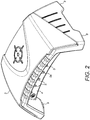
- the display unit 2 is in the form of a shaped box that contains a control module (not shown) and a visual display panel 4 that is positioned on one wall of the box such that it will be in the driver's field of vision when the display unit 2 is mounted on the bonnet 3.
- the display unit 2 shown in figure 2 is mounted on the bonnet 3 on the outside of the tractor 1 (and is not within the cab or inside of the tractor 1 or vehicle).
- the display unit is mountable within the user's field of vision when they are looking ahead of the vehicle.
- the display unit 2 is in the form of a box or casing, with the lower surface shaped appropriately to sit on the surface of a tractor or agricultural vehicle bonnet 3- typically this is an arcuate shape with four rubberised feet 9 portions that will contact the bonnet 3 surface.
- At least part of the underside surface of the display unit 2 that is going to come into contact with the bonnet 3 is a magnet or magnetised area.
- the four rubberised feet 9 are magnets that will attach to the metallic surface of the tractor bonnet 3.
- the display unit 2 could be an alternative shape.
- the bonnet 3 to which the unit 2 is to be fixed does not have an appropriate metal surface, metal discs or elements can be provided which can first be affixed to the bonnet 3, or alternative fixing mechanisms could be used.
- the display unit 2 is positioned or positionable on the bonnet 3 between 0.5 and 3 meters from the operator's position when driving and within, but not disrupting, the operator's field of vision when looking out of the front of the cab.
- This has the significant advantage that the visual display panel 4 is within the user's field of vision but is not obscuring their vision. As such, the user is not required to look back and forward between objects.
- This provides a safety aspect, as the driver remains looking at the field in front of them (with the visual display panel 4 simply sitting within the field of vision), reduced driver fatigue (due to the reduced requirement for rapid and repeated visual accommodation between distant and near objects) and improved performance as the driver is immediately aware of any deviation from the preferred path 7.
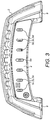
- the visual display panel 4 comprises a number of lights or LEDs 5 as best seen in figure 2 and figure 3 .
- the LEDs 5 are selected to be visible when lit even in bright sunlight conditions.
- the LEDs 5 form an array of lights of a size that can easily be seen by the user.
- the brightness of the LEDs 5 can also be variable and also the LEDs 5 flash and speeds are also controlled variably.
- the display unit 2 also contains a GPS antenna and transmitter/sensor.
- the GPS sensor receives location information from GPS that is representative of the geographic position of the tractor 1.
- the display unit 2 also contains a power source, which in this example is in the form of a battery.
- the display unit 2 can also contain an inertial measurement unit (IMU ) device or means for detecting velocity, acceleration and magnetic orientation.
- IMU inertial measurement unit
- An IMU measures and reports a body's specific force, angular rate, and sometimes the magnetic field surrounding the body, using a combination of accelerometers and gyroscopes, sometimes also magnetometers.
- the GPS antenna is housed in the display unit 2, it could in fact be separate from the display unit 2 and independently mountable on or in the tractor 1. It is however particularly beneficial to have as much as possible of the required navigational equipment within the casing or housing of the display unit as the allows it to be easily portable - the user simply needs the display unit, which can be used with the user's preferred user interface device - for example a tablet or mobile phone. This is particularly useful in cases where a user may want to quickly transfer the system to another agricultural vehicle, overcoming the need to purchase multiple units for multiple vehicles.
- the tractor 1 is to be guided according to a map that is stored in a guidance module and which identifies a preferred route or travel path 7, as shown in figure 4 .
- the guidance module is provided with a user interface on a mobile phone 8 that the driver of the vehicle has in the vehicle cab.
- the device could be a proprietary unit, but could also be a tablet, mobile phone or similar device onto which the software for the guidance module is provided e.g. it may be downloadable as an app.
- the guidance module is integrated into a product that is separate to the display unit 2 such that it can be taken into the cab of the tractor 1 and accessed by the user whilst the display unit 2 and associated visual display panel 4 remains outside of the tractor 1.
- the map may include information representative of the preferred route or travel path 7 of the tractor 1 in the field 6 and the guidance module may take into account details regarding the vehicle and mode of operation thereof. For example, a centerline or A-B line may be defined on the map based on the size of the field and the dimensions of the vehicle e.g. a 12 meter fertiliser spread trajectory.
- the guidance module receives positioning information via Bluetooth® from the control module, and GPS antenna (and data from the IMU) and continuously or semi-continuously compares the GPS location of the vehicle 1 to the preferred travel path 7 on the map to determine whether the tractor 1 is on course or deviating from the preferred travel path 7.
- the system converts this information into a visual signal for the driver by transmitting data, via Bluetooth®, to the control module in the display unit 2.
- seven LEDs 5 are arranged horizontally, and symmetrically about the center-line of the visual display panel 4 and facing the tractor cab.
- the center LED 5a is green and the remaining LEDs 5 are red.
- the LEDs 5 on the visual display panel 4 are controlled by the control module (which receives information via Bluetooth® from the guidance module) and change depending on whether the tractor 1 is moving along a predetermined preferred travel path 7 or whether it is moving off the preferred direction or vector of travel.
- the control module which receives information via Bluetooth® from the guidance module
- the central LED 5a on the visual display panel 4 will show as a green light.
- all of the LEDs 5 will be green when the tractor is on the preferred travel path 7.
- the control module will, in accordance with the data received from the guidance module, cause the visual display panel to indicate this to the driver.
- one or more of the LEDs 5b, 5c and 5d which are positioned to the right side of the driver's field of vision (and to the right of the central LED 5a) will light up with a red colour - and in some embodiments the central LED may either change colour, dim or go off. The more red lights that are lit, the further off course the vehicle is and the more corrective action is required by the driver.
- the central green LED 5a will light up and the red lights 5b, 5c and 5d to the right will go off.
- a similar array of red lights, 5x, 5y, 5z are provided to the left of the central light 5a.
- the visual display indicates the direction in which to make a course correction (i.e. to the right or to the left) and relative magnitude of the course correction.
- the calculations regarding how many lights to turn on or off are carried out by the guidance module, although could occur in the control module. For example, if the vehicle deviates to the right of line, a light will illuminate to indicate to the operator to steer to the left.
- the illuminated light may be turned off (if the course correction has been successful) or an additional adjacent light may be illuminated (if the course correction has been unsuccessful) to indicate the result of the correction.
- the operator continues to make course corrections until the center light 5a of the array is illuminated thereby indicating that the course of the vehicle coincides with preferred travel path 7.
- the display unit 2 is also provided with a power button and/or a charging and power LED which can indicate the power status of the display unit 2.
- the system also provides guidance when turning from one pass to the next.
- Some guidance systems do provide some guidance by directing the operator/driver using the lights/LEDs as they are approaching the end of a pass, however the turns are often inaccurate and the current systems work to correct any deviation from the new lie rather than avoiding deviation.
- the system uses the previous turn or the previous part of a turn to guide the operator of the tractor or vehicle during the turn.
- the system uses the IMU and GPS sensors in the device and the GPS position to record the turn the user makes off of the previous pass. This recorded data is used to predict the next turn onto the preferred travel path and enhances the accuracy and the experience for the user.
- the application will sense this rapidly and begin to map the path of the vehicle by looking at the recorded data and predicting the curvature of the turn.
- the sensors within the hardware device will assist with this.
- the LEDs will work normally according to steering angle required until a new preferred path is determined in the usual way. The predicted turn onto the preferred path will then be applied to this new line.
Landscapes
- Engineering & Computer Science (AREA)
- Radar, Positioning & Navigation (AREA)
- Remote Sensing (AREA)
- Life Sciences & Earth Sciences (AREA)
- Automation & Control Theory (AREA)
- Physics & Mathematics (AREA)
- General Physics & Mathematics (AREA)
- Mechanical Engineering (AREA)
- Soil Sciences (AREA)
- Environmental Sciences (AREA)
- Navigation (AREA)
- Lighting Device Outwards From Vehicle And Optical Signal (AREA)
- Guiding Agricultural Machines (AREA)
- Multimedia (AREA)
- Catching Or Destruction (AREA)
- Position Fixing By Use Of Radio Waves (AREA)
Claims (11)
- Präzisionsführungssystem für ein Fahrzeug (1), umfassend;
eine tragbare Anzeigevorrichtung (2), die ein Außengehäuse, ein oder mehrere visuelle Elemente und ein Anzeigesteuerungsmodul umfasst;
eine Stromquelle, die innerhalb des Außengehäuses der tragbaren Anzeigevorrichtung (2) beherbergt ist;
einen globalen Positionsbestimmungssystem- (GPS) -sensor, der konfiguriert ist, Informationen zu empfangen, die einen geografischen Standort des Fahrzeugs darstellen, wobei der GPS-Sensor innerhalb des Außengehäuses der tragbaren Anzeigevorrichtung (2) beherbergt ist;
ein Führungsmodul, das Kartendaten beinhaltet und das angepasst ist, Fahrtwege (7) zu definieren und die GPS-Daten von dem GPS-Sensor zu verarbeiten, indem die Standortdaten von dem GPS-Sensor mit den Kartendaten verglichen werden, um zu bestimmen, ob das Fahrzeug auf einem definierten Fahrtweg (7) ist;
wobei die tragbare Anzeigevorrichtung (2) Informationen von dem Führungsmodul empfängt und eine visuelle Anzeige über die visuellen Elemente bereitstellt, ob das Fahrzeug (1) auf dem definierten Fahrtweg (7) ist;
und wobei die tragbare Anzeigevorrichtung (2) auf der Motorhaube (3), an der Außenseite des Fahrzeugs (1), innerhalb des Blickfelds des Benutzers angebracht werden kann. - Präzisionsführungssystem nach Anspruch 1, wobei das System weiter eine Trägheitsmesseinheit- (IMU) -vorrichtung oder ein Mittel zum Detektieren von Geschwindigkeit, Beschleunigung und/oder magnetischer Ausrichtung umfasst.
- Präzisionsführungssystem nach einem der vorstehenden Ansprüche, wobei ein Abschnitt des Außengehäuses ein Anzeigepanel (4) ist, das eine Vielzahl von visuellen Elementen umfasst, die Lichter, die ein- oder ausgeschaltet werden können, und/oder lichtemittierende Dioden (LEDs 5) sein können.
- Präzisionsführungssystem nach Anspruch 3, wobei die Vielzahl von visuellen Elementen ein Array bilden.
- Präzisionsführungssystem nach einem der vorstehenden Ansprüche, wobei die Bodenoberfläche des Außengehäuses einen oder mehrere Magneten oder magnetisierte Bereiche umfasst.
- Präzisionsführungssystem nach einem der vorstehenden Ansprüche, wobei das Außengehäuse so geformt ist, dass die untere Oberfläche mindestens teilweise bogenförmig ist.
- Präzisionsführungssystem nach einem der vorstehenden Ansprüche, wobei die untere Oberfläche des Außengehäuses so eingerichtet ist, dass sie einen oder mehrere Füße (9) aufweist, die an der Außenoberfläche des Fahrzeugs (1) befestigt sind.
- Präzisionsführungssystem nach einem der vorstehenden Ansprüche, wobei die GPS-Daten mittels drahtloser Kommunikation, wie Bluetooth®, an das Führungsmodul übertragen werden.
- Präzisionsführungssystem nach Anspruch 2, wobei die Trägheitsmesseinheits- (IMU) -vorrichtung innerhalb des Außengehäuses der Anzeigevorrichtung enthalten ist.
- Präzisionsführungssystem nach einem der vorstehenden Ansprüche, wobei Informationen von dem Führungsmodul an das Anzeigesteuermodul oder die Anzeigevorrichtung (2) mittels drahtloser Technologie, wie Bluetooth®, übertragen werden.
- Präzisionsführungssystem nach einem der vorstehenden Ansprüche, wobei das Führungsmodul als Software, bevorzugt herunterladbare Software, bereitgestellt ist, die auf einem Mobiltelefon oder Tablet laufen kann.
Priority Applications (1)
| Application Number | Priority Date | Filing Date | Title |
|---|---|---|---|
| PL17792151T PL3534684T3 (pl) | 2016-11-02 | 2017-10-26 | System precyzyjnego prowadzenia dla pojazdów rolniczych |
Applications Claiming Priority (2)
| Application Number | Priority Date | Filing Date | Title |
|---|---|---|---|
| GB1618452.5A GB2555590A (en) | 2016-11-02 | 2016-11-02 | Improvements to precision guidance system for agricultural vehicles |
| PCT/GB2017/053227 WO2018083448A1 (en) | 2016-11-02 | 2017-10-26 | Improvements to precision guidance system for agricultural vehicles |
Publications (2)
| Publication Number | Publication Date |
|---|---|
| EP3534684A1 EP3534684A1 (de) | 2019-09-11 |
| EP3534684B1 true EP3534684B1 (de) | 2021-07-07 |
Family
ID=57963568
Family Applications (1)
| Application Number | Title | Priority Date | Filing Date |
|---|---|---|---|
| EP17792151.7A Active EP3534684B1 (de) | 2016-11-02 | 2017-10-26 | Präzisionsführungssystemen für landwirtschaftliche fahrzeuge |
Country Status (8)
| Country | Link |
|---|---|
| US (1) | US11221220B2 (de) |
| EP (1) | EP3534684B1 (de) |
| AU (1) | AU2017352853B2 (de) |
| CA (1) | CA3040387C (de) |
| ES (1) | ES2886268T3 (de) |
| GB (1) | GB2555590A (de) |
| PL (1) | PL3534684T3 (de) |
| WO (1) | WO2018083448A1 (de) |
Families Citing this family (6)
| Publication number | Priority date | Publication date | Assignee | Title |
|---|---|---|---|---|
| NL2015542B1 (en) * | 2015-10-01 | 2017-04-20 | Rexnord Flattop Europe Bv | Planning system and method for maintaining a cycle time in an automobile factory. |
| DE102018203051A1 (de) * | 2018-03-01 | 2019-09-05 | Robert Bosch Gmbh | Agrarsystem |
| US11367279B1 (en) | 2019-04-19 | 2022-06-21 | David R. Wilmot | Sensors, sod harvester with the sensors and methods for steering or guiding sod harvesters |
| US12256671B2 (en) | 2021-05-19 | 2025-03-25 | Cnh Industrial America Llc | Agricultural system and method for automatically controlling a position of a harvesting implement of an agricultural harvester |
| US12078738B2 (en) | 2021-11-09 | 2024-09-03 | Msrs Llc | Method, apparatus, and computer readable medium for a multi-source reckoning system |
| US12259246B1 (en) | 2024-05-13 | 2025-03-25 | Msrs Llc | Method, apparatus, and computer readable medium for calculating a handrail influence intensity factor |
Family Cites Families (11)
| Publication number | Priority date | Publication date | Assignee | Title |
|---|---|---|---|---|
| US5987383C1 (en) * | 1997-04-28 | 2006-06-13 | Trimble Navigation Ltd | Form line following guidance system |
| US5945917A (en) * | 1997-12-18 | 1999-08-31 | Rockwell International | Swathing guidance display |
| US6199000B1 (en) * | 1998-07-15 | 2001-03-06 | Trimble Navigation Limited | Methods and apparatus for precision agriculture operations utilizing real time kinematic global positioning system systems |
| US6539303B2 (en) * | 2000-12-08 | 2003-03-25 | Mcclure John A. | GPS derived swathing guidance system |
| JP4086237B2 (ja) * | 2003-07-07 | 2008-05-14 | 本田技研工業株式会社 | 車両用ナビゲーションシステム |
| US7451030B2 (en) * | 2005-02-04 | 2008-11-11 | Novariant, Inc. | System and method for interactive selection and determination of agricultural vehicle guide paths offset from each other with varying curvature along their length |
| US7739015B2 (en) * | 2007-07-31 | 2010-06-15 | Deere & Company | System and method for controlling a vehicle with a sequence of vehicle events |
| US8655538B2 (en) * | 2011-12-16 | 2014-02-18 | Agco Corporation | Systems and methods for switching display modes in agricultural vehicles |
| EP3150966B1 (de) | 2012-07-27 | 2019-06-26 | Harman Becker Automotive Systems GmbH | Navigationssystem und verfahren zur navigation |
| US9756773B1 (en) * | 2016-02-26 | 2017-09-12 | International Business Machines Corporation | System and method for application of materials through coordination with automated data collection vehicles |
| US10143126B2 (en) * | 2016-06-10 | 2018-12-04 | Cnh Industrial America Llc | Planning and control of autonomous agricultural operations |
-
2016
- 2016-11-02 GB GB1618452.5A patent/GB2555590A/en not_active Withdrawn
-
2017
- 2017-10-26 CA CA3040387A patent/CA3040387C/en active Active
- 2017-10-26 WO PCT/GB2017/053227 patent/WO2018083448A1/en not_active Ceased
- 2017-10-26 ES ES17792151T patent/ES2886268T3/es active Active
- 2017-10-26 AU AU2017352853A patent/AU2017352853B2/en active Active
- 2017-10-26 PL PL17792151T patent/PL3534684T3/pl unknown
- 2017-10-26 US US16/344,862 patent/US11221220B2/en active Active
- 2017-10-26 EP EP17792151.7A patent/EP3534684B1/de active Active
Also Published As
| Publication number | Publication date |
|---|---|
| CA3040387A1 (en) | 2018-05-11 |
| US20190265044A1 (en) | 2019-08-29 |
| ES2886268T3 (es) | 2021-12-16 |
| NZ753065A (en) | 2023-11-24 |
| AU2017352853A1 (en) | 2019-05-23 |
| AU2017352853B2 (en) | 2021-11-11 |
| CA3040387C (en) | 2023-04-04 |
| US11221220B2 (en) | 2022-01-11 |
| EP3534684A1 (de) | 2019-09-11 |
| GB2555590A (en) | 2018-05-09 |
| GB201618452D0 (en) | 2016-12-14 |
| WO2018083448A1 (en) | 2018-05-11 |
| PL3534684T3 (pl) | 2021-12-27 |
Similar Documents
| Publication | Publication Date | Title |
|---|---|---|
| EP3534684B1 (de) | Präzisionsführungssystemen für landwirtschaftliche fahrzeuge | |
| US11867516B2 (en) | Vehicle manual guidance systems with steering wheel angle sensors and road wheel angle sensors | |
| US8145390B2 (en) | Swath finder feature integrated with multipurpose display | |
| US7885745B2 (en) | GNSS control system and method | |
| US9002566B2 (en) | Visual, GNSS and gyro autosteering control | |
| US5945917A (en) | Swathing guidance display | |
| USRE48154E1 (en) | System and method for integrating automatic electrical steering with GNSS guidance | |
| JP7526142B2 (ja) | 走行経路管理システム | |
| JP7445721B2 (ja) | 自動走行システム | |
| US7191061B2 (en) | Auto-steering apparatus and method | |
| KR20200055159A (ko) | 농업용 작업차 | |
| JP2016011024A (ja) | 植播系圃場作業機 | |
| KR20210038427A (ko) | 영역 등록 시스템 | |
| JP2020101467A (ja) | 圃場形状生成システム及び農作業車 | |
| JP6669225B2 (ja) | 苗移植機 | |
| EP4023043A1 (de) | Fahrunterstützungssystem | |
| JP7038651B2 (ja) | 圃場作業機及び農作業支援システム | |
| JP2019022524A (ja) | 作業機 | |
| JP2022099083A (ja) | 表示システム | |
| JP6669226B2 (ja) | 苗移植機 | |
| NZ753065B2 (en) | Improvements to precision guidance system for agricultural vehicles |
Legal Events
| Date | Code | Title | Description |
|---|---|---|---|
| STAA | Information on the status of an ep patent application or granted ep patent |
Free format text: STATUS: UNKNOWN |
|
| STAA | Information on the status of an ep patent application or granted ep patent |
Free format text: STATUS: THE INTERNATIONAL PUBLICATION HAS BEEN MADE |
|
| PUAI | Public reference made under article 153(3) epc to a published international application that has entered the european phase |
Free format text: ORIGINAL CODE: 0009012 |
|
| STAA | Information on the status of an ep patent application or granted ep patent |
Free format text: STATUS: REQUEST FOR EXAMINATION WAS MADE |
|
| 17P | Request for examination filed |
Effective date: 20190513 |
|
| AK | Designated contracting states |
Kind code of ref document: A1 Designated state(s): AL AT BE BG CH CY CZ DE DK EE ES FI FR GB GR HR HU IE IS IT LI LT LU LV MC MK MT NL NO PL PT RO RS SE SI SK SM TR |
|
| AX | Request for extension of the european patent |
Extension state: BA ME |
|
| DAV | Request for validation of the european patent (deleted) | ||
| DAX | Request for extension of the european patent (deleted) | ||
| REG | Reference to a national code |
Ref country code: DE Ref legal event code: R079 Ref document number: 602017041744 Country of ref document: DE Free format text: PREVIOUS MAIN CLASS: A01B0069040000 Ipc: G01C0021200000 |
|
| GRAP | Despatch of communication of intention to grant a patent |
Free format text: ORIGINAL CODE: EPIDOSNIGR1 |
|
| STAA | Information on the status of an ep patent application or granted ep patent |
Free format text: STATUS: GRANT OF PATENT IS INTENDED |
|
| RIC1 | Information provided on ipc code assigned before grant |
Ipc: A01B 79/00 20060101ALN20210208BHEP Ipc: G01C 21/20 20060101AFI20210208BHEP Ipc: A01B 69/04 20060101ALN20210208BHEP |
|
| RIC1 | Information provided on ipc code assigned before grant |
Ipc: A01B 69/04 20060101ALN20210216BHEP Ipc: A01B 79/00 20060101ALN20210216BHEP Ipc: G01C 21/20 20060101AFI20210216BHEP |
|
| INTG | Intention to grant announced |
Effective date: 20210309 |
|
| GRAS | Grant fee paid |
Free format text: ORIGINAL CODE: EPIDOSNIGR3 |
|
| GRAA | (expected) grant |
Free format text: ORIGINAL CODE: 0009210 |
|
| STAA | Information on the status of an ep patent application or granted ep patent |
Free format text: STATUS: THE PATENT HAS BEEN GRANTED |
|
| AK | Designated contracting states |
Kind code of ref document: B1 Designated state(s): AL AT BE BG CH CY CZ DE DK EE ES FI FR GB GR HR HU IE IS IT LI LT LU LV MC MK MT NL NO PL PT RO RS SE SI SK SM TR |
|
| REG | Reference to a national code |
Ref country code: GB Ref legal event code: FG4D |
|
| REG | Reference to a national code |
Ref country code: AT Ref legal event code: REF Ref document number: 1409015 Country of ref document: AT Kind code of ref document: T Effective date: 20210715 |
|
| REG | Reference to a national code |
Ref country code: DE Ref legal event code: R096 Ref document number: 602017041744 Country of ref document: DE |
|
| REG | Reference to a national code |
Ref country code: IE Ref legal event code: FG4D |
|
| REG | Reference to a national code |
Ref country code: NL Ref legal event code: FP |
|
| REG | Reference to a national code |
Ref country code: FI Ref legal event code: FGE |
|
| REG | Reference to a national code |
Ref country code: NO Ref legal event code: T2 Effective date: 20210707 |
|
| REG | Reference to a national code |
Ref country code: LT Ref legal event code: MG9D |
|
| REG | Reference to a national code |
Ref country code: AT Ref legal event code: MK05 Ref document number: 1409015 Country of ref document: AT Kind code of ref document: T Effective date: 20210707 |
|
| REG | Reference to a national code |
Ref country code: ES Ref legal event code: FG2A Ref document number: 2886268 Country of ref document: ES Kind code of ref document: T3 Effective date: 20211216 |
|
| PG25 | Lapsed in a contracting state [announced via postgrant information from national office to epo] |
Ref country code: LT Free format text: LAPSE BECAUSE OF FAILURE TO SUBMIT A TRANSLATION OF THE DESCRIPTION OR TO PAY THE FEE WITHIN THE PRESCRIBED TIME-LIMIT Effective date: 20210707 Ref country code: AT Free format text: LAPSE BECAUSE OF FAILURE TO SUBMIT A TRANSLATION OF THE DESCRIPTION OR TO PAY THE FEE WITHIN THE PRESCRIBED TIME-LIMIT Effective date: 20210707 Ref country code: BG Free format text: LAPSE BECAUSE OF FAILURE TO SUBMIT A TRANSLATION OF THE DESCRIPTION OR TO PAY THE FEE WITHIN THE PRESCRIBED TIME-LIMIT Effective date: 20211007 Ref country code: PT Free format text: LAPSE BECAUSE OF FAILURE TO SUBMIT A TRANSLATION OF THE DESCRIPTION OR TO PAY THE FEE WITHIN THE PRESCRIBED TIME-LIMIT Effective date: 20211108 Ref country code: SE Free format text: LAPSE BECAUSE OF FAILURE TO SUBMIT A TRANSLATION OF THE DESCRIPTION OR TO PAY THE FEE WITHIN THE PRESCRIBED TIME-LIMIT Effective date: 20210707 Ref country code: RS Free format text: LAPSE BECAUSE OF FAILURE TO SUBMIT A TRANSLATION OF THE DESCRIPTION OR TO PAY THE FEE WITHIN THE PRESCRIBED TIME-LIMIT Effective date: 20210707 Ref country code: HR Free format text: LAPSE BECAUSE OF FAILURE TO SUBMIT A TRANSLATION OF THE DESCRIPTION OR TO PAY THE FEE WITHIN THE PRESCRIBED TIME-LIMIT Effective date: 20210707 |
|
| PG25 | Lapsed in a contracting state [announced via postgrant information from national office to epo] |
Ref country code: LV Free format text: LAPSE BECAUSE OF FAILURE TO SUBMIT A TRANSLATION OF THE DESCRIPTION OR TO PAY THE FEE WITHIN THE PRESCRIBED TIME-LIMIT Effective date: 20210707 Ref country code: GR Free format text: LAPSE BECAUSE OF FAILURE TO SUBMIT A TRANSLATION OF THE DESCRIPTION OR TO PAY THE FEE WITHIN THE PRESCRIBED TIME-LIMIT Effective date: 20211008 |
|
| REG | Reference to a national code |
Ref country code: DE Ref legal event code: R097 Ref document number: 602017041744 Country of ref document: DE |
|
| PG25 | Lapsed in a contracting state [announced via postgrant information from national office to epo] |
Ref country code: DK Free format text: LAPSE BECAUSE OF FAILURE TO SUBMIT A TRANSLATION OF THE DESCRIPTION OR TO PAY THE FEE WITHIN THE PRESCRIBED TIME-LIMIT Effective date: 20210707 |
|
| PLBE | No opposition filed within time limit |
Free format text: ORIGINAL CODE: 0009261 |
|
| STAA | Information on the status of an ep patent application or granted ep patent |
Free format text: STATUS: NO OPPOSITION FILED WITHIN TIME LIMIT |
|
| PG25 | Lapsed in a contracting state [announced via postgrant information from national office to epo] |
Ref country code: SM Free format text: LAPSE BECAUSE OF FAILURE TO SUBMIT A TRANSLATION OF THE DESCRIPTION OR TO PAY THE FEE WITHIN THE PRESCRIBED TIME-LIMIT Effective date: 20210707 Ref country code: SK Free format text: LAPSE BECAUSE OF FAILURE TO SUBMIT A TRANSLATION OF THE DESCRIPTION OR TO PAY THE FEE WITHIN THE PRESCRIBED TIME-LIMIT Effective date: 20210707 Ref country code: RO Free format text: LAPSE BECAUSE OF FAILURE TO SUBMIT A TRANSLATION OF THE DESCRIPTION OR TO PAY THE FEE WITHIN THE PRESCRIBED TIME-LIMIT Effective date: 20210707 Ref country code: EE Free format text: LAPSE BECAUSE OF FAILURE TO SUBMIT A TRANSLATION OF THE DESCRIPTION OR TO PAY THE FEE WITHIN THE PRESCRIBED TIME-LIMIT Effective date: 20210707 Ref country code: AL Free format text: LAPSE BECAUSE OF FAILURE TO SUBMIT A TRANSLATION OF THE DESCRIPTION OR TO PAY THE FEE WITHIN THE PRESCRIBED TIME-LIMIT Effective date: 20210707 |
|
| 26N | No opposition filed |
Effective date: 20220408 |
|
| REG | Reference to a national code |
Ref country code: BE Ref legal event code: MM Effective date: 20211031 |
|
| PG25 | Lapsed in a contracting state [announced via postgrant information from national office to epo] |
Ref country code: MC Free format text: LAPSE BECAUSE OF FAILURE TO SUBMIT A TRANSLATION OF THE DESCRIPTION OR TO PAY THE FEE WITHIN THE PRESCRIBED TIME-LIMIT Effective date: 20210707 |
|
| PG25 | Lapsed in a contracting state [announced via postgrant information from national office to epo] |
Ref country code: LU Free format text: LAPSE BECAUSE OF NON-PAYMENT OF DUE FEES Effective date: 20211026 Ref country code: IT Free format text: LAPSE BECAUSE OF FAILURE TO SUBMIT A TRANSLATION OF THE DESCRIPTION OR TO PAY THE FEE WITHIN THE PRESCRIBED TIME-LIMIT Effective date: 20210707 Ref country code: BE Free format text: LAPSE BECAUSE OF NON-PAYMENT OF DUE FEES Effective date: 20211031 |
|
| P01 | Opt-out of the competence of the unified patent court (upc) registered |
Effective date: 20230522 |
|
| PG25 | Lapsed in a contracting state [announced via postgrant information from national office to epo] |
Ref country code: CY Free format text: LAPSE BECAUSE OF FAILURE TO SUBMIT A TRANSLATION OF THE DESCRIPTION OR TO PAY THE FEE WITHIN THE PRESCRIBED TIME-LIMIT Effective date: 20210707 |
|
| PG25 | Lapsed in a contracting state [announced via postgrant information from national office to epo] |
Ref country code: HU Free format text: LAPSE BECAUSE OF FAILURE TO SUBMIT A TRANSLATION OF THE DESCRIPTION OR TO PAY THE FEE WITHIN THE PRESCRIBED TIME-LIMIT; INVALID AB INITIO Effective date: 20171026 |
|
| PG25 | Lapsed in a contracting state [announced via postgrant information from national office to epo] |
Ref country code: MK Free format text: LAPSE BECAUSE OF FAILURE TO SUBMIT A TRANSLATION OF THE DESCRIPTION OR TO PAY THE FEE WITHIN THE PRESCRIBED TIME-LIMIT Effective date: 20210707 |
|
| PG25 | Lapsed in a contracting state [announced via postgrant information from national office to epo] |
Ref country code: MT Free format text: LAPSE BECAUSE OF FAILURE TO SUBMIT A TRANSLATION OF THE DESCRIPTION OR TO PAY THE FEE WITHIN THE PRESCRIBED TIME-LIMIT Effective date: 20210707 |
|
| REG | Reference to a national code |
Ref country code: CH Ref legal event code: U11 Free format text: ST27 STATUS EVENT CODE: U-0-0-U10-U11 (AS PROVIDED BY THE NATIONAL OFFICE) Effective date: 20251101 |
|
| PGFP | Annual fee paid to national office [announced via postgrant information from national office to epo] |
Ref country code: NL Payment date: 20251023 Year of fee payment: 9 |
|
| PG25 | Lapsed in a contracting state [announced via postgrant information from national office to epo] |
Ref country code: TR Free format text: LAPSE BECAUSE OF FAILURE TO SUBMIT A TRANSLATION OF THE DESCRIPTION OR TO PAY THE FEE WITHIN THE PRESCRIBED TIME-LIMIT Effective date: 20210707 |
|
| PGFP | Annual fee paid to national office [announced via postgrant information from national office to epo] |
Ref country code: DE Payment date: 20251024 Year of fee payment: 9 |
|
| PGFP | Annual fee paid to national office [announced via postgrant information from national office to epo] |
Ref country code: GB Payment date: 20251013 Year of fee payment: 9 |
|
| PGFP | Annual fee paid to national office [announced via postgrant information from national office to epo] |
Ref country code: NO Payment date: 20251021 Year of fee payment: 9 |
|
| PGFP | Annual fee paid to national office [announced via postgrant information from national office to epo] |
Ref country code: FI Payment date: 20251017 Year of fee payment: 9 |
|
| PGFP | Annual fee paid to national office [announced via postgrant information from national office to epo] |
Ref country code: FR Payment date: 20251017 Year of fee payment: 9 |
|
| PGFP | Annual fee paid to national office [announced via postgrant information from national office to epo] |
Ref country code: CH Payment date: 20251101 Year of fee payment: 9 |
|
| PGFP | Annual fee paid to national office [announced via postgrant information from national office to epo] |
Ref country code: IE Payment date: 20251013 Year of fee payment: 9 Ref country code: CZ Payment date: 20251013 Year of fee payment: 9 |
|
| PGFP | Annual fee paid to national office [announced via postgrant information from national office to epo] |
Ref country code: PL Payment date: 20251014 Year of fee payment: 9 |
|
| PGFP | Annual fee paid to national office [announced via postgrant information from national office to epo] |
Ref country code: ES Payment date: 20251104 Year of fee payment: 9 |