EP3534495A1 - Feuille magnétique de stator, procédé associé et machine électrique rotative - Google Patents
Feuille magnétique de stator, procédé associé et machine électrique rotative Download PDFInfo
- Publication number
- EP3534495A1 EP3534495A1 EP19159571.9A EP19159571A EP3534495A1 EP 3534495 A1 EP3534495 A1 EP 3534495A1 EP 19159571 A EP19159571 A EP 19159571A EP 3534495 A1 EP3534495 A1 EP 3534495A1
- Authority
- EP
- European Patent Office
- Prior art keywords
- stator
- sheet
- openings
- electrical machine
- magnetic sheet
- Prior art date
- Legal status (The legal status is an assumption and is not a legal conclusion. Google has not performed a legal analysis and makes no representation as to the accuracy of the status listed.)
- Pending
Links
Images


Classifications
-
- H—ELECTRICITY
- H02—GENERATION; CONVERSION OR DISTRIBUTION OF ELECTRIC POWER
- H02K—DYNAMO-ELECTRIC MACHINES
- H02K1/00—Details of the magnetic circuit
- H02K1/06—Details of the magnetic circuit characterised by the shape, form or construction
- H02K1/12—Stationary parts of the magnetic circuit
- H02K1/18—Means for mounting or fastening magnetic stationary parts on to, or to, the stator structures
- H02K1/185—Means for mounting or fastening magnetic stationary parts on to, or to, the stator structures to outer stators
-
- H—ELECTRICITY
- H02—GENERATION; CONVERSION OR DISTRIBUTION OF ELECTRIC POWER
- H02K—DYNAMO-ELECTRIC MACHINES
- H02K1/00—Details of the magnetic circuit
- H02K1/06—Details of the magnetic circuit characterised by the shape, form or construction
- H02K1/12—Stationary parts of the magnetic circuit
-
- H—ELECTRICITY
- H02—GENERATION; CONVERSION OR DISTRIBUTION OF ELECTRIC POWER
- H02K—DYNAMO-ELECTRIC MACHINES
- H02K15/00—Methods or apparatus specially adapted for manufacturing, assembling, maintaining or repairing of dynamo-electric machines
- H02K15/02—Methods or apparatus specially adapted for manufacturing, assembling, maintaining or repairing of dynamo-electric machines of stator or rotor bodies
Definitions
- This invention relates to a magnetic sheet for a stator of a rotating electrical machine. This invention also relates to a rotating electrical machine comprising such a magnetic sheet and a method of manufacturing such a magnetic sheet.
- a rotating electrical machine has a stator in which is inserted a rotor, and it can weigh several tens of tons. For example, a 2-pole rotating electrical machine developing 37 MW weighs 46 tons.
- its mass may be greater than the maximum permissible mass.
- One method of reducing the mass of the machine would be to lighten the rotor or stator by creating them from materials of lower density, e.g. by replacing copper by aluminum in the stator and rotor windings.
- Another method of reducing the mass of the machine would be to reduce the volume of material incorporated into the rotor.
- the electrical characteristics of the rotating electrical machine are directly proportional to the volume of cuprous and ferrous materials incorporated into the rotor.
- the stator of a rotating electrical machine may comprise a stack of magnetic sheets of substantially circular shape held together by tie rods or bars.
- the tie rods or bars compact and hold the magnetic sheets.
- the stator magnetic sheets have a recess in their center intended to hold a rotor.
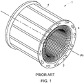
- Fig. 1 shows an example of a laminated stator 1 of an electrical machine known from the prior art comprising an axis of revolution (A).
- the stator has a mass of e.g. 25 tons and an external diameter of 2 meters.
- the stack of magnetic plates in the stator weighs 19 tons.
- the stator 1 comprises packets of magnetic sheets 2 compacted between two clamping plates 3 arranged on either side of the stator and connected by tie rods 4.
- the plates 3 and the tie rods 4 forming the frame of the stator hold the packets of compacted sheets.
- Fig. 2 shows a portion of a magnetic sheet 2 according to the prior art.
- the magnetic sheet comprises a yoke 5 and teeth 6.
- the yoke 5 comprises holes 7 intended to accommodate the tie rods 4 and a sheet zone 8 located between the teeth 6 and the holes 7.
- the teeth 6 form notches intended to accommodate the stator windings generating a magnetic field.
- the torque developed by the rotating electrical machine is directly proportional to the magnetic flux generated by the windings circulating in the zone 8 of the sheet 2.
- the surface 8 of the sheet located between the holes 7 and the teeth 6 is dimensioned such that the electrical and mechanical characteristics of a rotating electrical machine incorporating the magnetic sheet 2 are optimal.
- a stator magnetic sheet for a rotary electrical machine comprising a yoke comprising a fixation zone configured to fix the sheet in the stator of the rotating electrical machine and located on an external periphery of the sheet and comprising openings intended to accommodate connecting means configured to hold the stator magnetic sheet in the stator.
- the fixation zone comprises indentations configured such that each of the openings is surrounded by a cord of sheet with a width greater than or equal to a minimum value.
- the openings are distributed uniformly over the external periphery.
- the openings comprise indented circular holes.
- the openings comprise rectangular, square or elliptical holes.
- a stator for a rotating electrical machine comprising connecting means configured to maintain a plurality of stator magnetic sheets as defined above.
- the connecting means comprise tie rods with a circular section and the openings comprise indented circular holes.
- the connecting means comprise bars with a rectangular section and the openings comprise rectangular holes.
- the magnetic sheets are circular.
- a rotating electrical machine comprising a stator as defined above.
- a method for producing a stator magnetic sheet is provided for a rotary electrical machine comprising a yoke comprising a fixation zone configured to fix the sheet in the stator of the rotating electrical machine and located on an external periphery of the sheet and comprising openings intended to accommodate connecting means configured to hold the stator magnetic sheet in the stator.
- the fixation zone is indented such that each of the openings is surrounded by a cord of sheet with a width greater than or equal to a minimum value.
- the openings are distributed uniformly over the external periphery.
- openings of an indented circular shape are made.
- a method for producing a stator comprising a plurality of stator magnetic sheets as defined above.
- FIG. 3 illustrates an embodiment of a stator S of a rotating electrical machine.
- the stator S comprises a cylindrical metal structure, tie rods 9 with a circular section and stacks of annular compacted magnetic sheets 10. It further comprises electrical stator windings (not shown), which are intended to be connected to a control device (not shown).
- the magnetic sheets 10 have a circular shape
- the magnetic sheets may be of any shape, e.g. square, comprising a circular central recess intended to accommodate a rotor of the rotating electrical machine.
- the axis of rotation of the cylindrical metallic structure is represented by the axis (R).
- the metal structure comprises two clamping plates P and connection means here comprising tie rods 9.
- the magnetic sheets 10 are compacted axially between the two clamping plates P connected to each other by the connecting means.
- the metal structure thus ensures the compaction and contributes to the rigidity of the stator.
- the connecting means are fixed to the clamping plates e.g. by welding or screwing.
- the connecting means pass through the sheets 10 such as to hold the magnetic sheets 10 in the stator S.
- first connecting means connect the clamping plates and second connecting means hold the magnetic sheets 10 in the stator S.
- the rotor of the rotating electrical machine is inserted in the center of the metallic structure such that the axis of rotation of the rotor coincides substantially with the axis (R).
- the magnetic sheets 10 are grouped into packets of sheets that can be separated from each other by spacers arranged between them to create a ventilation duct between the packets of magnetic sheets 10.
- Fig. 4 illustrates a portion of a stator magnetic sheet 10.
- the sheet 10 comprises teeth 11 and a yoke 12.
- the yoke 12 is located on the external periphery of the sheet 10 and extends as far as the teeth 11 located on the internal periphery of the sheet.
- the teeth 11 form notches intended to accommodate the electrical stator windings.
- the yoke 12 comprises a fixation zone 13 located on the external periphery of the stator magnetic sheet, which serves to fix the sheet 10 in the stator S, and a magnetic flux channeling zone 14 located between the teeth 11 and the fixation zone 13.
- the torque delivered by a rotating electrical machine incorporating the stator S is proportional to the magnetic flux generated by the stator electrical windings circulating in the channeling zone 14.
- the magnetic flux channeling zone 14 is dimensioned such that the rotating electrical machine incorporating the stator S provides the desired torque.
- the fixation zone 13 comprises openings 15 configured to accommodate the connecting means and indentations 16 configured such that each of the openings 15 is surrounded by a sheet cord C with a width greater than or equal to a minimum value t min .
- the indentations 16 make it possible to remove material from the sheet 10 without compromising the rigidity of the sheet 10 and ensuring the fixation of the sheet in the stator S.
- the indentations 16 make it possible to reduce the mass of the sheet 10.
- An opening 15 surrounded by a sheet cord C forms a fixation lug 17.
- the value t min of the width of the cord C is determined such that the rigidity of the fixation lug 17 is sufficient to hold and compact the stator magnetic sheets in the stator STAT and the torque transfer.
- the width of the cord C is greater than the value t min .
- the openings 15 are preferably uniformly distributed over the external periphery of the sheet as shown here or distributed unevenly over the sheet.
- the connecting means comprise tie rods 9 with a circular section, and therefore the openings 15 of the fixation lugs 17 have a circular shape.
- the connecting means comprise bars with a rectangular section.
- the openings 15 are configured to accommodate the bars, i.e. the openings 15 are rectangular.
- any section shape e.g. an elliptical or square section, is conceivable.
- the indentations 16 are made e.g. by laser cutting, stamping or any method known to those skilled in the art.
- fixation zone 14 is indented such that each of the openings 15 is surrounded by a sheet cord C whose width is greater than or equal to a minimum value t min .
- the openings 15 in the lugs 17 are made e.g. by punching, laser cutting or any method known to those skilled in the art.
- the lugs 17 may be indented as shown here to facilitate the ejection of the cutting residue in the case of obtaining the openings 15 by punching or so as to optimize the trajectory of a laser cutting head.
- the indentations 16 make it possible to lighten the mass of the stator magnetic sheets.
- the indentations 16 make it possible to lighten the stator by 1.5 tons while preserving the magnetic properties of the stator, i.e. a lightening of the stator plates of 8%.
- the indentations 16 make it possible to remove material from the stator S without modifying the magnetic flux channeling zone.
- the mass of the stator S is lightened while preserving the magnetic characteristics of the stator.
Landscapes
- Engineering & Computer Science (AREA)
- Power Engineering (AREA)
- Manufacturing & Machinery (AREA)
- Iron Core Of Rotating Electric Machines (AREA)
Applications Claiming Priority (1)
| Application Number | Priority Date | Filing Date | Title |
|---|---|---|---|
| FR1851759A FR3078452B1 (fr) | 2018-02-28 | 2018-02-28 | Tole magnetique statorique, procede et machine electrique tournante associes |
Publications (1)
| Publication Number | Publication Date |
|---|---|
| EP3534495A1 true EP3534495A1 (fr) | 2019-09-04 |
Family
ID=62455675
Family Applications (1)
| Application Number | Title | Priority Date | Filing Date |
|---|---|---|---|
| EP19159571.9A Pending EP3534495A1 (fr) | 2018-02-28 | 2019-02-27 | Feuille magnétique de stator, procédé associé et machine électrique rotative |
Country Status (3)
| Country | Link |
|---|---|
| US (1) | US10903698B2 (fr) |
| EP (1) | EP3534495A1 (fr) |
| FR (1) | FR3078452B1 (fr) |
Citations (5)
| Publication number | Priority date | Publication date | Assignee | Title |
|---|---|---|---|---|
| GB1092864A (en) * | 1964-02-14 | 1967-11-29 | English Electric Co Ltd | Improvements in or relating to dynamo electric machine segmental stator core plates |
| EP0793332A1 (fr) * | 1996-02-28 | 1997-09-03 | Moteurs Leroy-Somer | Secteur circulaire pour tÔle statorique, stator de machine dynamo-électrique constitué à partir de tels secteurs et machine dynamo-électrique comportant un tel stator |
| US20060279160A1 (en) * | 2005-06-08 | 2006-12-14 | Denso Corporation | Rotary electric machine with a stator core made of magnetic steel sheets and the stator core thereof |
| WO2008067706A1 (fr) * | 2006-12-07 | 2008-06-12 | Wuxi Kipor Power Co., Ltd | Stator destiné à un générateur à aimant permanent à rotor interne multipôles |
| US20130002086A1 (en) * | 2011-06-30 | 2013-01-03 | GM Global Technology Operations LLC | Segmented stator core |
Family Cites Families (2)
| Publication number | Priority date | Publication date | Assignee | Title |
|---|---|---|---|---|
| US1795882A (en) * | 1928-06-16 | 1931-03-10 | Westinghouse Electric & Mfg Co | Generator-core punching |
| US2818515A (en) * | 1954-10-12 | 1957-12-31 | Rade Koncar Tvornica Elek Cnih | Stators for electrical machines |
-
2018
- 2018-02-28 FR FR1851759A patent/FR3078452B1/fr active Active
-
2019
- 2019-02-27 EP EP19159571.9A patent/EP3534495A1/fr active Pending
- 2019-02-28 US US16/288,232 patent/US10903698B2/en active Active
Patent Citations (5)
| Publication number | Priority date | Publication date | Assignee | Title |
|---|---|---|---|---|
| GB1092864A (en) * | 1964-02-14 | 1967-11-29 | English Electric Co Ltd | Improvements in or relating to dynamo electric machine segmental stator core plates |
| EP0793332A1 (fr) * | 1996-02-28 | 1997-09-03 | Moteurs Leroy-Somer | Secteur circulaire pour tÔle statorique, stator de machine dynamo-électrique constitué à partir de tels secteurs et machine dynamo-électrique comportant un tel stator |
| US20060279160A1 (en) * | 2005-06-08 | 2006-12-14 | Denso Corporation | Rotary electric machine with a stator core made of magnetic steel sheets and the stator core thereof |
| WO2008067706A1 (fr) * | 2006-12-07 | 2008-06-12 | Wuxi Kipor Power Co., Ltd | Stator destiné à un générateur à aimant permanent à rotor interne multipôles |
| US20130002086A1 (en) * | 2011-06-30 | 2013-01-03 | GM Global Technology Operations LLC | Segmented stator core |
Also Published As
| Publication number | Publication date |
|---|---|
| FR3078452A1 (fr) | 2019-08-30 |
| FR3078452B1 (fr) | 2022-03-11 |
| US20190267853A1 (en) | 2019-08-29 |
| US10903698B2 (en) | 2021-01-26 |
Similar Documents
| Publication | Publication Date | Title |
|---|---|---|
| EP0280194B1 (fr) | Construction de tôle pour machine électro-dynamique | |
| EP2200160B1 (fr) | Rotateur pour moteur électrique à induction, moteur électrique à induction, compresseur, ventilateur et dispositif de climatisation | |
| EP0144448B1 (fr) | Procede de fabrication d'un rotor a champ magnetique permanent | |
| US4395816A (en) | Method of making dynamoelectric machine rotor having cast conductors and radial coolant ducts | |
| DE102015223766A1 (de) | Elektrische Maschine | |
| US4341966A (en) | Laminated dynamoelectric machine rotor having cast conductors and radial coolant ducts and method of making same | |
| US3401280A (en) | Fabricated squirrel cage rotor construction for electric motor and method of assembling the same | |
| EP0052179B1 (fr) | Machine électrique à flux axial | |
| JPS6350943B2 (fr) | ||
| DE112017000357T5 (de) | Magnetgetriebegerät | |
| EP3349333B1 (fr) | Rotor de machine électrique rotative | |
| JP4717089B2 (ja) | 電動機の固定子及び電動機及び圧縮機及び送風機 | |
| US3590301A (en) | Rotor for dynamoelectric machine | |
| US11211852B2 (en) | Magnetic circuit for rotating electrical machine element, method and associated electrical machine | |
| EP3534495A1 (fr) | Feuille magnétique de stator, procédé associé et machine électrique rotative | |
| CN113875127A (zh) | 转子冷却 | |
| US4281266A (en) | Dynamoelectric machine with flux screen | |
| GB2194104A (en) | Laminated stator core unit for dynamo-electric machine | |
| JP2015202027A (ja) | ロータ | |
| US20110266896A1 (en) | Rotating electric machine | |
| US2058362A (en) | Laminated core for electrical apparatus | |
| JP3658483B2 (ja) | 回転電機の回転子 | |
| SE428620B (sv) | Elmaskin | |
| GB2090479A (en) | Asynchronous electric machines and rotors therefor | |
| JP2016152725A (ja) | 仮カシメを有する積層体及びその製造方法並びに積層鉄心の製造方法 |
Legal Events
| Date | Code | Title | Description |
|---|---|---|---|
| PUAI | Public reference made under article 153(3) epc to a published international application that has entered the european phase |
Free format text: ORIGINAL CODE: 0009012 |
|
| STAA | Information on the status of an ep patent application or granted ep patent |
Free format text: STATUS: THE APPLICATION HAS BEEN PUBLISHED |
|
| AK | Designated contracting states |
Kind code of ref document: A1 Designated state(s): AL AT BE BG CH CY CZ DE DK EE ES FI FR GB GR HR HU IE IS IT LI LT LU LV MC MK MT NL NO PL PT RO RS SE SI SK SM TR |
|
| AX | Request for extension of the european patent |
Extension state: BA ME |
|
| STAA | Information on the status of an ep patent application or granted ep patent |
Free format text: STATUS: REQUEST FOR EXAMINATION WAS MADE |
|
| 17P | Request for examination filed |
Effective date: 20200107 |
|
| STAA | Information on the status of an ep patent application or granted ep patent |
Free format text: STATUS: EXAMINATION IS IN PROGRESS |
|
| 17Q | First examination report despatched |
Effective date: 20200921 |
|
| STAA | Information on the status of an ep patent application or granted ep patent |
Free format text: STATUS: EXAMINATION IS IN PROGRESS |
|
| RAP3 | Party data changed (applicant data changed or rights of an application transferred) |
Owner name: GE ENERGY POWER CONVERSION TECHNOLOGY LTD |
|
| P01 | Opt-out of the competence of the unified patent court (upc) registered |
Effective date: 20230530 |