EP3534450B1 - Elektrodenanordnung und lithiumsekundärbatterie die diese enthält - Google Patents
Elektrodenanordnung und lithiumsekundärbatterie die diese enthält Download PDFInfo
- Publication number
- EP3534450B1 EP3534450B1 EP18823670.7A EP18823670A EP3534450B1 EP 3534450 B1 EP3534450 B1 EP 3534450B1 EP 18823670 A EP18823670 A EP 18823670A EP 3534450 B1 EP3534450 B1 EP 3534450B1
- Authority
- EP
- European Patent Office
- Prior art keywords
- active material
- electrode active
- column
- material layer
- holes
- Prior art date
- Legal status (The legal status is an assumption and is not a legal conclusion. Google has not performed a legal analysis and makes no representation as to the accuracy of the status listed.)
- Active
Links
Images


Classifications
-
- H—ELECTRICITY
- H01—ELECTRIC ELEMENTS
- H01M—PROCESSES OR MEANS, e.g. BATTERIES, FOR THE DIRECT CONVERSION OF CHEMICAL ENERGY INTO ELECTRICAL ENERGY
- H01M50/00—Constructional details or processes of manufacture of the non-active parts of electrochemical cells other than fuel cells, e.g. hybrid cells
- H01M50/40—Separators; Membranes; Diaphragms; Spacing elements inside cells
- H01M50/46—Separators, membranes or diaphragms characterised by their combination with electrodes
-
- H—ELECTRICITY
- H01—ELECTRIC ELEMENTS
- H01M—PROCESSES OR MEANS, e.g. BATTERIES, FOR THE DIRECT CONVERSION OF CHEMICAL ENERGY INTO ELECTRICAL ENERGY
- H01M4/00—Electrodes
- H01M4/02—Electrodes composed of, or comprising, active material
- H01M4/13—Electrodes for accumulators with non-aqueous electrolyte, e.g. for lithium-accumulators; Processes of manufacture thereof
-
- H—ELECTRICITY
- H01—ELECTRIC ELEMENTS
- H01M—PROCESSES OR MEANS, e.g. BATTERIES, FOR THE DIRECT CONVERSION OF CHEMICAL ENERGY INTO ELECTRICAL ENERGY
- H01M10/00—Secondary cells; Manufacture thereof
- H01M10/05—Accumulators with non-aqueous electrolyte
- H01M10/058—Construction or manufacture
- H01M10/0585—Construction or manufacture of accumulators having only flat construction elements, i.e. flat positive electrodes, flat negative electrodes and flat separators
-
- H—ELECTRICITY
- H01—ELECTRIC ELEMENTS
- H01M—PROCESSES OR MEANS, e.g. BATTERIES, FOR THE DIRECT CONVERSION OF CHEMICAL ENERGY INTO ELECTRICAL ENERGY
- H01M10/00—Secondary cells; Manufacture thereof
- H01M10/05—Accumulators with non-aqueous electrolyte
- H01M10/052—Li-accumulators
-
- H—ELECTRICITY
- H01—ELECTRIC ELEMENTS
- H01M—PROCESSES OR MEANS, e.g. BATTERIES, FOR THE DIRECT CONVERSION OF CHEMICAL ENERGY INTO ELECTRICAL ENERGY
- H01M4/00—Electrodes
- H01M4/02—Electrodes composed of, or comprising, active material
- H01M4/04—Processes of manufacture in general
- H01M4/043—Processes of manufacture in general involving compressing or compaction
- H01M4/0433—Molding
-
- H—ELECTRICITY
- H01—ELECTRIC ELEMENTS
- H01M—PROCESSES OR MEANS, e.g. BATTERIES, FOR THE DIRECT CONVERSION OF CHEMICAL ENERGY INTO ELECTRICAL ENERGY
- H01M4/00—Electrodes
- H01M4/02—Electrodes composed of, or comprising, active material
- H01M4/13—Electrodes for accumulators with non-aqueous electrolyte, e.g. for lithium-accumulators; Processes of manufacture thereof
- H01M4/139—Processes of manufacture
-
- H—ELECTRICITY
- H01—ELECTRIC ELEMENTS
- H01M—PROCESSES OR MEANS, e.g. BATTERIES, FOR THE DIRECT CONVERSION OF CHEMICAL ENERGY INTO ELECTRICAL ENERGY
- H01M4/00—Electrodes
- H01M4/02—Electrodes composed of, or comprising, active material
- H01M4/64—Carriers or collectors
- H01M4/70—Carriers or collectors characterised by shape or form
- H01M4/75—Wires, rods or strips
-
- H—ELECTRICITY
- H01—ELECTRIC ELEMENTS
- H01M—PROCESSES OR MEANS, e.g. BATTERIES, FOR THE DIRECT CONVERSION OF CHEMICAL ENERGY INTO ELECTRICAL ENERGY
- H01M50/00—Constructional details or processes of manufacture of the non-active parts of electrochemical cells other than fuel cells, e.g. hybrid cells
- H01M50/40—Separators; Membranes; Diaphragms; Spacing elements inside cells
- H01M50/463—Separators, membranes or diaphragms characterised by their shape
-
- H—ELECTRICITY
- H01—ELECTRIC ELEMENTS
- H01M—PROCESSES OR MEANS, e.g. BATTERIES, FOR THE DIRECT CONVERSION OF CHEMICAL ENERGY INTO ELECTRICAL ENERGY
- H01M2220/00—Batteries for particular applications
- H01M2220/20—Batteries in motive systems, e.g. vehicle, ship, plane
-
- H—ELECTRICITY
- H01—ELECTRIC ELEMENTS
- H01M—PROCESSES OR MEANS, e.g. BATTERIES, FOR THE DIRECT CONVERSION OF CHEMICAL ENERGY INTO ELECTRICAL ENERGY
- H01M2220/00—Batteries for particular applications
- H01M2220/30—Batteries in portable systems, e.g. mobile phone, laptop
-
- Y—GENERAL TAGGING OF NEW TECHNOLOGICAL DEVELOPMENTS; GENERAL TAGGING OF CROSS-SECTIONAL TECHNOLOGIES SPANNING OVER SEVERAL SECTIONS OF THE IPC; TECHNICAL SUBJECTS COVERED BY FORMER USPC CROSS-REFERENCE ART COLLECTIONS [XRACs] AND DIGESTS
- Y02—TECHNOLOGIES OR APPLICATIONS FOR MITIGATION OR ADAPTATION AGAINST CLIMATE CHANGE
- Y02E—REDUCTION OF GREENHOUSE GAS [GHG] EMISSIONS, RELATED TO ENERGY GENERATION, TRANSMISSION OR DISTRIBUTION
- Y02E60/00—Enabling technologies; Technologies with a potential or indirect contribution to GHG emissions mitigation
- Y02E60/10—Energy storage using batteries
-
- Y—GENERAL TAGGING OF NEW TECHNOLOGICAL DEVELOPMENTS; GENERAL TAGGING OF CROSS-SECTIONAL TECHNOLOGIES SPANNING OVER SEVERAL SECTIONS OF THE IPC; TECHNICAL SUBJECTS COVERED BY FORMER USPC CROSS-REFERENCE ART COLLECTIONS [XRACs] AND DIGESTS
- Y02—TECHNOLOGIES OR APPLICATIONS FOR MITIGATION OR ADAPTATION AGAINST CLIMATE CHANGE
- Y02P—CLIMATE CHANGE MITIGATION TECHNOLOGIES IN THE PRODUCTION OR PROCESSING OF GOODS
- Y02P70/00—Climate change mitigation technologies in the production process for final industrial or consumer products
- Y02P70/50—Manufacturing or production processes characterised by the final manufactured product
Definitions
- the present disclosure relates to an electrode assembly and a lithium secondary battery including the same. More particularly, the present disclosure relates to an electrode assembly including a positive electrode, a separator and a negative electrode stacked in a novel shape, and a lithium secondary battery including the same.
- Such a lithium secondary battery includes a positive electrode, a separator, a negative electrode and an electrolyte. Lithium ions deintercalated from a positive electrode active material upon the first charge are intercalated into a negative electrode active material, such as carbon particles, and then deintercalated again therefrom upon discharge. In this manner, lithium ions function to transfer energy, while they reciprocate between both electrodes, and thus the lithium secondary battery is rechargeable.
- lithium secondary batteries having high energy density and voltage, long cycle life and a low self-discharging rate have been commercialized and used widely.
- a high-capacity battery such as electric vehicles and hybrid electric vehicles capable of substituting for vehicles using fossil fuel, including gasoline vehicles and diesel vehicles, one of the main causes of air pollution.
- a power source for such systems there is a need for designing a high-capacity electrode for manufacturing a lithium secondary battery having high energy density, high output and high discharge voltage.
- the present disclosure is designed to solve the problems of the related art, and therefore the present disclosure is directed to providing an electrode assembly having a novel shape capable of preventing cracking and separation of an electrode active material layer and a lithium secondary battery including the same.
- an electrode assembly including a positive electrode current collector, a positive electrode active material layer, a separator, a negative electrode active material layer and a negative electrode current collector stacked successively, wherein a plurality of through-holes is formed to pass through the positive electrode active material layer, separator and the negative electrode active material layer,
- the positive electrode current collector includes a first sheet-like current collector and a plurality of first column-like current collectors extended from the first sheet-like current collector along the thickness direction of the electrode assembly and passing through a part of the through-holes
- the negative electrode current collector includes a second sheet-like current collector and a plurality of second column-like current collectors extended from the second sheet-like current collector along the thickness direction of the electrode assembly and passing through the remaining through-holes other than the part of the through-holes.
- the first column-like current collectors may be formed in such a manner that they are extended along the thickness direction of the electrode assembly to reach the second sheet-like current collector.
- the second column-like current collectors may be formed in such a manner that they are extended along the thickness direction of the electrode assembly to reach the first sheet-like current collector.
- first column-like current collectors pass through the through-holes formed in the positive electrode active material layer while being in close contact with the inner circumferential surfaces thereof
- second column-like current collectors pass through the through-holes formed in the negative electrode active material layer while being in close contact with the inner circumferential surfaces thereof.
- first column-like current collectors pass through the through-holes formed in the negative electrode active material layer while being in close contact with the inner circumferential surfaces thereof
- second column-like current collectors pass through the through-holes formed in the positive electrode active material layer while being in close contact with the inner circumferential surfaces thereof
- the first column-like current collectors includes a first insulation layer formed on the surface of the portion where they are in contact with the negative electrode active material layer
- the second column-like current collectors includes a second insulation layer formed on the surface of the portion where they are in contact with the positive electrode active material layer.
- each of the first insulation layer and the second insulation layer may be independently a varnish coating layer, insulating polymer coating layer or an insulating inorganic coating layer.
- the part of the through-holes through which the first column-like current collectors pass and the remaining through-holes through which the second column-like current collectors pass may be disposed alternately with each other.
- the positive electrode active material layer in which the through-holes are formed may be a product obtained by introducing a positive electrode active material slurry to an electrode mold having a plurality of columns, and then heating and compressing the positive electrode active material slurry.
- the negative electrode active material layer in which the through-holes are formed may be a product obtained by introducing a negative electrode active material slurry to an electrode mold having a plurality of columns, and then heating and compressing the negative electrode active material slurry.
- a lithium secondary battery including the electrode assembly according to the present disclosure.
- column-like current collectors pass through a plurality of through-holes formed in electrode active material layers to provide an electrode assembly.
- an electrode assembly having a rigid block shape.
- a positive electrode current collector, a positive electrode active material layer, a negative electrode active material layer and a negative electrode current collector are stacked in a block shape to produce an electrode assembly.
- a positive electrode current collector, a positive electrode active material layer, a negative electrode active material layer and a negative electrode current collector are stacked in a block shape to produce an electrode assembly.
- the column-like current collectors passing through the electrode active material layers are in close contact with the inner circumferential surfaces of the through-holes formed in the electrode active material layers. Thus, it is possible to reduce the internal resistance of the electrode.
- FIG. 1 is a schematic view illustrating a positive electrode current collector and a negative electrode current collector according to an embodiment of the present disclosure
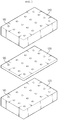
- FIG. 2 is a schematic view illustrating a positive electrode active material layer, separator and a negative electrode active material layer having a plurality of through-holes according to an embodiment of the present disclosure
- FIG. 3 is a schematic view illustrating the electrode assembly obtained according to an embodiment of the present disclosure.
- the electrode assembly 100 is an electrode assembly 100 including a positive electrode current collector 110, a positive electrode active material layer 120, a separator 130, a negative electrode active material layer 140 and a negative electrode current collector 150 stacked successively, wherein a plurality of through-holes 160 is formed to pass through the positive electrode active material layer 120, separator 130 and the negative electrode active material layer 140, the positive electrode current collector 110 includes a first sheet-like current collector 111 and a plurality of first column-like current collectors 112 extended from the first sheet-like current collector 111 along the thickness direction of the electrode assembly 100 and passing through a part of the through-holes 160, and the negative electrode current collector 150 includes a second sheet-like current collector 151 and a plurality of second column-like current collectors 152 extended from the second sheet-like current collector 151 along the thickness direction of the electrode assembly 100 and passing through the remaining through-holes other than the part of the through-holes 160.
- an electrode assembly generally includes a positive electrode having a sheet-like positive electrode current collector and a positive electrode active material layer formed thereon, and a negative electrode including a sheet-like negative electrode current collector and a negative electrode active material layer formed thereon, stacked simply with a sheet-like separator interposed therebetween.
- the column-like current collectors 112, 152 pass through the through-holes 160 formed in the electrode active material layers 120, 140 and the separator to provide the electrode assembly. Therefore, it is possible to produce an electrode assembly in the form of a rigid block.
- the first column-like current collectors 112 may be formed in such a manner that they pass through the through-holes 160, are extended along the thickness direction of the electrode assembly 100 and reach the second sheet-like current collector 151 of the counter electrode.
- the second column-like current collectors 152 may be formed in such a manner that they pass through the through-holes 160, are extended along the thickness direction of the electrode assembly 100 and reach the first sheet-like current collector 111 of the counter electrode.
- an insulation layer may be formed at the portion where the first column-like current collectors 112 are in contact with the second sheet-like current collector 151 and at the portion where the second column-like current collectors 152 are in contact with the first sheet-like current collector 111 to interrupt electrical connection.
- first column-like current collectors 112 pass through the through-holes 160 formed in the positive electrode active material layer 120 while being in close contact with the inner circumferential surfaces thereof.
- second column-like current collectors 152 pass through the through-holes 160 formed in the negative electrode active material layer 140 while being in close contact with the inner circumferential surfaces thereof. Therefore, it is possible to increase the area where each electrode current collector is in contact with each electrode active material layer, and thus to reduce the internal resistance of each electrode.
- first column-like current collectors 112 pass through the through-holes 160 formed in the positive electrode active material layer 120 while being in close contact with the inner circumferential surfaces thereof and pass through the through-holes 160 formed in the negative electrode active material layer 140 while being in close contact with the inner circumferential surfaces thereof.
- second column-like current collectors 152 pass through the through-holes 160 formed in the negative electrode active material layer 140 while being in close contact with the inner circumferential surfaces thereof and pass through the through-holes 160 formed in the positive electrode active material layer 120 while being in close contact with the inner circumferential surfaces thereof.
- the first column-like current collectors 112 may include a first insulation layer formed on the surface of the portion where they are in contact with the negative electrode active material layer 140
- the second column-like current collectors 152 may include a second insulation layer formed on the surface of the portion where they are in contact with the positive electrode active material layer 120.
- each of the first insulation layer and the second insulation layer may independently include a varnish coating layer, insulating polymer coating layer or an insulating inorganic coating layer.
- the part of the through-holes and the remaining through-holes may be disposed with no particular limitation and may be disposed independently as a separate group at one portion.
- the part of the through-holes and the remaining through-holes may be disposed alternately with each other. In this manner, force may be applied uniformly to the first column-like current collector and to the second column-like current collectors. Thus, it is possible to assembly a more rigid electrode assembly.
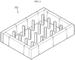
- FIG. 4 is a schematic view illustrating an electrode mold configured to form an electrode active material layer according to an embodiment of the present disclosure.
- the electrode active material layer having a plurality of through-holes may be a product obtained by introducing an electrode active material slurry to an electrode mold 200 having a plurality of columns, and then heating and compressing the electrode active material slurry.
- a block-shaped electrode active material layer When a block-shaped electrode active material layer is obtained through an electrode mold, it may be stored merely by stacking without winding for storage. Thus, it is possible to fundamentally prevent separation of an electrode active material layer, which, otherwise, may occur when an electrode sheet is wound for storage according to the related art.
- the positive electrode active material slurry according to the present disclosure is prepared by mixing a positive electrode active material, a conductive material, a binder and a solvent.
- the positive electrode active material may include a lithium-containing oxide, and a lithium-containing transition metal oxide may be used preferably.
- a lithium-containing transition metal oxide may be used preferably.
- it is possible to use any one selected from the group consisting of Li x CoO 2 (0.5 ⁇ x ⁇ 1.3), Li x NiO 2 (0.5 ⁇ x ⁇ 1.3), Li x MnO 2 (0.5 ⁇ x ⁇ 1.3), Li x Mn 2 O 4 (0.5 ⁇ x ⁇ 1.3), Li x (Ni a Co b Mn c )O 2 (0.5 ⁇ x ⁇ 1.3, 0 ⁇ a ⁇ 1, 0 ⁇ b ⁇ 1, 0 ⁇ c ⁇ 1, a + b + c 1), Li x Ni 1-y CO y O 2 (0.5 ⁇ x ⁇ 1.3, 0 ⁇ y ⁇ 1), Li x Co 1-y Mn y O 2 (0.5 ⁇ x ⁇ 1.3,
- the conductive material is not particularly limited, as long as it is an electroconductive material causing no chemical change in an electrochemical device.
- the conductive material that may be used includes carbon black, graphite, carbon fibers, carbon nanotubes, metal powder, conductive metal oxide, inorganic conductive material, or the like.
- Particular examples of commercially available conductive materials include acetylene black series (available from Chevron Chemical Company or Gulf Oil Company), Ketjen Black EC series (available from Armak Company), Vulcan XC-72 (available from Cabot Company) and Super P (available from MMM Company).
- acetylene black series available from Chevron Chemical Company or Gulf Oil Company
- Ketjen Black EC series available from Armak Company
- Vulcan XC-72 available from Cabot Company
- Super P available from MMM Company
- the negative electrode active material slurry according to the present disclosure is prepared by mixing a negative electrode active material, a conductive material, a binder and a solvent.
- the negative electrode active material may include lithium metal, a carbonaceous material, metal compound or a combination thereof, which is capable of lithium ion intercalation/deintercalation.
- the carbonaceous material may include low-crystalline carbon and high-crystalline carbon.
- Typical examples of low-crystalline carbon include soft carbon and hard carbon
- those of high-crystalline carbon include natural graphite, Kish graphite, pyrolytic carbon, mesophase pitch based carbon fibers, meso-carbon microbeads, mesophase pitches and high-temperature baked carbon, such as petroleum or coal tar pitch derived cokes.
- the metal compound include compounds containing at least one of metal elements, such as Si, Ge, Sn, Pb, P, Sb, Bi, Al, Ga, In, Ti, Mn, Fe, Co, Ni, Cu, Zn, Ag, Mg, Sr and Ba.
- the metal compound may be used in any form, such as simple substance, alloy, oxide (TiO 2 , SnO 2 , or the like), nitride, sulfide, boride or alloy with lithium.
- a metal compound that may contain at least one element selected from Si, Ge and Sn and includes at least one element selected from Si and Sn may provide a battery with higher capacity.
- the binder used for the positive electrode and the negative electrode functions to connect positive electrode active material particles and negative electrode active material particles among themselves. It is possible to use a conventional binder with no particular limitation.
- binders such as polyvinylidene fluoride-co-hexafluoropropylene (PVDF-co-HFP), polyvinylidene fluoride (PVDF), polyacrylonitrile, polymethyl methacrylate, styrene butadiene rubber (SBR) and carboxymethyl cellulose (CMC).
- PVDF-co-HFP polyvinylidene fluoride-co-hexafluoropropylene
- PVDF polyvinylidene fluoride
- SBR styrene butadiene rubber
- CMC carboxymethyl cellulose
- each of the positive electrode current collector and the negative electrode current collector may be any highly conductive metal that has no reactivity in the voltage range of the corresponding battery.
- the positive electrode current collector include foil made of aluminum, nickel or a combination thereof.
- the negative electrode current collector include foil made of copper, gold, nickel, copper alloy or a combination thereof.
- the current collector may include stacked substrates made of such materials.
- the separator according to the present disclosure may be any porous polymer substrate used for a conventional electrochemical device.
- the separator may include a polyolefin-based porous polymer membrane or non-woven web, but is not limited thereto.
- polystyrene-based porous polymer membrane examples include membranes formed of any one of polyolefin polymers, such as polyethylene, including high-density polyethylene, linear low-density polyethylene, low-density polyethylene and ultrahigh-molecular weight polyethylene, polypropylene, polybutylene and polypentene, or a polymer blend thereof.
- polyethylene including high-density polyethylene, linear low-density polyethylene, low-density polyethylene and ultrahigh-molecular weight polyethylene, polypropylene, polybutylene and polypentene, or a polymer blend thereof.
- the non-woven web include a non-woven web formed of any one of polyethylene terephthalate, polybutylene terephthalate, polyester, polyacetal, polyamide, polycarbonate, polyimide, polyetheretherketone, polyethersulfone, polyphenylene oxide, polyphenylene sulfide and polyethylene naphthalate, or a polymer blend thereof, in addition to a polyolefin-based non-woven web.
- the non-woven web may have a structure of a spun-bonded non-woven web including long fibers or a melt blown non-woven web.
- the porous polymer substrate may have a thickness of 5-50 ⁇ m.
- the pore size and porosity of the pores present in the porous polymer substrate are not particularly limited, the pore size and porosity may be 0.01-50 ⁇ m and 10-95%, respectively.
- the electrode assembly according to the present disclosure may be used for manufacturing an electrochemical device.
- the electrochemical device includes any device which carries out electrochemical reaction, and particular examples thereof include all types of secondary batteries, fuel cells, solar cells or capacitors such as super capacitor devices.
- the secondary batteries lithium secondary batteries, including lithium metal secondary batteries, lithium ion secondary batteries, lithium polymer secondary batteries or lithium ion polymer ion batteries, are preferred.
Landscapes
- Chemical & Material Sciences (AREA)
- Chemical Kinetics & Catalysis (AREA)
- Electrochemistry (AREA)
- General Chemical & Material Sciences (AREA)
- Engineering & Computer Science (AREA)
- Manufacturing & Machinery (AREA)
- Materials Engineering (AREA)
- Battery Electrode And Active Subsutance (AREA)
- Secondary Cells (AREA)
- Cell Electrode Carriers And Collectors (AREA)
- Cell Separators (AREA)
- Fuel Cell (AREA)
- Electric Double-Layer Capacitors Or The Like (AREA)
Claims (6)
- Elektrodenanordnung (100), umfassend einen Positive-Elektrode-Stromabnehmer (110), eine Positive-Elektrode-Aktivmaterialschicht (120), einen Separator (130), eine Negative-Elektrode-Aktivmaterialschicht (140) und einen Negative-Elektrode-Stromabnehmer (150), welche sukzessive gestapelt sind,wobei eine Mehrzahl von Durchgangslöchern (160) derart gebildet ist, dass sie die Positive-Elektrode-Aktivmaterialschicht (120), den Separator (130) und die Negative-Elektrode-Aktivmaterialschicht (140) durchsetzen,der Positive-Elektrode-Stromabnehmer (110) einen ersten blattartigen Stromabnehmer (111) und eine Mehrzahl erster säulenartiger Stromabnehmer (112) umfasst, welche sich von dem ersten blattartigen Stromabnehmer (110) entlang der Dickenrichtung der Elektrodenanordnung (100) erstrecken und einen Teil der Durchgangslöcher (160) durchsetzen, undder Negative-Elektrode-Stromabnehmer (150) einen zweiten blattartigen Stromabnehmer (151) und eine Mehrzahl zweiter säulenartiger Stromabnehmer (152) umfasst, welche sich von dem zweiten blattartigen Stromabnehmer (151) entlang der Dickenrichtung der Elektrodenanordnung (100) erstrecken und die verbleibenden Durchgangslöcher durchsetzen, welche von dem Teil der Durchgangslöcher (160) verschieden sind, welche die ersten säulenartigen Stromabnehmer (112) durchsetzen,wobei die ersten säulenartigen Stromabnehmer (112) die Durchgangslöcher (160) durchsetzen, welche in der Positive-Elektrode-Aktivmaterialschicht (120) gebildet sind, während sie in engem Kontakt mit den inneren Umfangsflächen davon sind, unddie zweiten säulenartigen Stromabnehmer (152) die Durchgangslöcher (160) durchsetzen, welche in der Negative-Elektrode-Aktivmaterialschicht (140) gebildet sind, während sie in engem Kontakt mit den inneren Umfangsflächen davon sind, undwobei die ersten säulenartigen Stromabnehmer (112) die Durchgangslöcher (160) durchsetzen, welche in der Negative-Elektrode-Aktivmaterialschicht (140) gebildet sind, während sie in engem Kontakt mit den inneren Umfangsflächen davon sind,die zweiten säulenartigen Stromabnehmer (152) die Durchgangslöcher (160) durchsetzen, welche in der Positive-Elektrode-Aktivmaterialschicht (120) gebildet sind, während sie in engem Kontakt mit den inneren Umfangsflächen davon sind,die ersten säulenartigen Stromabnehmer (112) eine erste Isolationsschicht umfassen, welche an der Fläche des Abschnitts gebildet ist, wo sie in Kontakt mit der Negative-Elektrode-Aktivmaterialschicht (140) sind, unddie zweiten säulenartigen Stromabnehmer (152) eine zweite Isolationsschicht umfassen, welche an der Fläche des Abschnitts gebildet ist, wo sie in Kontakt mit der Positive-Elektrode-Aktivmaterialschicht (120) sind.
- Elektrodenanordnung (100) nach Anspruch 1, wobei die ersten säulenartigen Stromabnehmer (112) in einer solchen Weise gebildet sind, dass sie sich entlang der Dickenrichtung der Elektrodenanordnung (100) derart erstrecken, dass sie in Kontakt mit dem zweiten blattartigen Stromabnehmer (151) sind.
- Elektrodenanordnung (100) nach Anspruch 1, wobei die zweiten säulenartigen Stromabnehmer (152) in einer solchen Weise gebildet sind, dass sie sich entlang der Dickenrichtung der Elektrodenanordnung (100) derart erstrecken, dass sie in Kontakt mit dem ersten blattartigen Stromabnehmer (111) sind.
- Elektrodenanordnung (100) nach Anspruch 1, wobei jede der ersten Isolationsschicht und der zweiten Isolationsschicht unabhängig eine Lackdeckschicht, eine isolierende Polymerdeckschicht oder eine isolierende anorganische Deckschicht ist.
- Elektrodenanordnung (100) nach Anspruch 1, wobei der Teil der Durchgangslöcher (160), welche die ersten säulenartigen Stromabnehmer durchsetzen, und die verbleibenden Durchgangslöcher, welche die zweiten säulenartigen Stromabnehmer durchsetzen, einander abwechselnd angeordnet sind.
- Lithiumsekundärbatterie, umfassend die wie in einem der Ansprüche 1 bis 5 definierte Elektrodenanordnung (100).
Priority Applications (1)
| Application Number | Priority Date | Filing Date | Title |
|---|---|---|---|
| PL18823670T PL3534450T3 (pl) | 2017-06-27 | 2018-06-21 | Zespół elektrodowy i zawierająca go litowa bateria akumulatorowa |
Applications Claiming Priority (2)
| Application Number | Priority Date | Filing Date | Title |
|---|---|---|---|
| KR1020170081480A KR102208515B1 (ko) | 2017-06-27 | 2017-06-27 | 전극 조립체 및 그를 포함하는 리튬 이차전지 |
| PCT/KR2018/007033 WO2019004655A1 (ko) | 2017-06-27 | 2018-06-21 | 전극 조립체 및 그를 포함하는 리튬 이차전지 |
Publications (3)
| Publication Number | Publication Date |
|---|---|
| EP3534450A1 EP3534450A1 (de) | 2019-09-04 |
| EP3534450A4 EP3534450A4 (de) | 2019-11-13 |
| EP3534450B1 true EP3534450B1 (de) | 2020-11-25 |
Family
ID=64742386
Family Applications (1)
| Application Number | Title | Priority Date | Filing Date |
|---|---|---|---|
| EP18823670.7A Active EP3534450B1 (de) | 2017-06-27 | 2018-06-21 | Elektrodenanordnung und lithiumsekundärbatterie die diese enthält |
Country Status (7)
| Country | Link |
|---|---|
| US (1) | US11081762B2 (de) |
| EP (1) | EP3534450B1 (de) |
| JP (1) | JP7037015B2 (de) |
| KR (1) | KR102208515B1 (de) |
| CN (2) | CN208400926U (de) |
| PL (1) | PL3534450T3 (de) |
| WO (1) | WO2019004655A1 (de) |
Families Citing this family (8)
| Publication number | Priority date | Publication date | Assignee | Title |
|---|---|---|---|---|
| US20220320539A1 (en) * | 2014-12-03 | 2022-10-06 | Global Energy Science, Llc | Unique electrodes for electrochemical cells |
| KR102208515B1 (ko) * | 2017-06-27 | 2021-01-26 | 주식회사 엘지화학 | 전극 조립체 및 그를 포함하는 리튬 이차전지 |
| JP7067019B2 (ja) * | 2017-10-30 | 2022-05-16 | セイコーエプソン株式会社 | 二次電池用電極、二次電池、電子機器、二次電池用電極の製造方法、二次電池の製造方法 |
| KR20220011158A (ko) * | 2019-05-22 | 2022-01-27 | 시온 파워 코퍼레이션 | 전기적으로 결합된 전극, 및 관련 물품 및 방법 |
| FR3110774B1 (fr) * | 2020-05-20 | 2022-04-15 | I Ten | Procédé de fabrication d’une batterie à ions de lithium |
| KR102699227B1 (ko) | 2020-05-14 | 2024-08-26 | 서강대학교산학협력단 | 탄피 계수 장치 |
| HUE066571T2 (hu) | 2020-05-14 | 2024-08-28 | Lg Energy Solution Ltd | Fokozott biztonságú elektródegység és azzal rendelkezõ másodlagos lítium akkumulátor |
| WO2025024963A1 (zh) * | 2023-07-28 | 2025-02-06 | 江苏新宜中澳环境技术有限公司 | 用于多个膜电容去离子电极组件的电极装置 |
Family Cites Families (19)
| Publication number | Priority date | Publication date | Assignee | Title |
|---|---|---|---|---|
| KR20070037209A (ko) | 2005-09-30 | 2007-04-04 | 삼성에스디아이 주식회사 | 액상의 연료를 사용하는 연료전지 |
| JP5135746B2 (ja) | 2006-09-21 | 2013-02-06 | トヨタ自動車株式会社 | リチウムイオン二次電池とその製造方法 |
| CN101536223B (zh) * | 2006-11-15 | 2012-02-22 | 松下电器产业株式会社 | 非水电解质二次电池用集电体及其制造方法、电极的制造方法以及非水电解质二次电池 |
| JP5224020B2 (ja) * | 2007-06-18 | 2013-07-03 | エス・イー・アイ株式会社 | リチウム二次電池 |
| JP2009076289A (ja) | 2007-09-20 | 2009-04-09 | Seiko Epson Corp | 発光管の製造方法、光源装置及びプロジェクタ |
| US8927156B2 (en) * | 2009-02-19 | 2015-01-06 | Semiconductor Energy Laboratory Co., Ltd. | Power storage device |
| JP2011151279A (ja) * | 2010-01-25 | 2011-08-04 | Sony Corp | 複合体電極及びこれを用いた電子デバイス |
| JP2012059396A (ja) * | 2010-09-06 | 2012-03-22 | Mitsubishi Electric Corp | 蓄電デバイス用負極及び蓄電デバイス並びにそれらの製造方法 |
| US8962190B1 (en) | 2010-12-17 | 2015-02-24 | Hrl Laboratories, Llc | Three-dimensional electrodes with conductive foam for electron and lithium-ion transport |
| JP6050073B2 (ja) | 2011-09-30 | 2016-12-21 | 株式会社半導体エネルギー研究所 | 蓄電装置 |
| JP6050106B2 (ja) | 2011-12-21 | 2016-12-21 | 株式会社半導体エネルギー研究所 | 非水二次電池用シリコン負極の製造方法 |
| JP2013182810A (ja) * | 2012-03-02 | 2013-09-12 | Tdk Corp | 集電体、およびそれを用いたリチウムイオン二次電池 |
| US20130236781A1 (en) | 2012-03-06 | 2013-09-12 | Semiconductor Energy Laboratory Co., Ltd. | Negative electrode for secondary battery and secondary battery |
| JP2013206705A (ja) * | 2012-03-28 | 2013-10-07 | Toyota Industries Corp | 蓄電装置及び二次電池並びに蓄電装置の製造方法 |
| KR101562435B1 (ko) | 2013-10-23 | 2015-10-22 | 전남대학교산학협력단 | 양극산화 템플릿을 이용한 3차원 구조의 광흡수층을 가지는 태양전지 제조 방법 |
| JP6316066B2 (ja) * | 2014-03-31 | 2018-04-25 | 積水化学工業株式会社 | リチウムイオン二次電池の製造方法 |
| KR101686600B1 (ko) * | 2014-07-04 | 2016-12-14 | 주식회사 엘지화학 | 전해액 함침용 홀을 포함하고 있는 전지셀 |
| KR101741412B1 (ko) * | 2014-10-29 | 2017-05-30 | 에스케이이노베이션 주식회사 | 이차 전지용 집전체와 전극 및 이를 포함한 이차 전지 |
| KR102208515B1 (ko) * | 2017-06-27 | 2021-01-26 | 주식회사 엘지화학 | 전극 조립체 및 그를 포함하는 리튬 이차전지 |
-
2017
- 2017-06-27 KR KR1020170081480A patent/KR102208515B1/ko active Active
-
2018
- 2018-06-13 CN CN201820914035.XU patent/CN208400926U/zh active Active
- 2018-06-13 CN CN201810606642.4A patent/CN109148797B/zh active Active
- 2018-06-21 PL PL18823670T patent/PL3534450T3/pl unknown
- 2018-06-21 JP JP2019526327A patent/JP7037015B2/ja active Active
- 2018-06-21 WO PCT/KR2018/007033 patent/WO2019004655A1/ko not_active Ceased
- 2018-06-21 EP EP18823670.7A patent/EP3534450B1/de active Active
- 2018-06-21 US US16/478,764 patent/US11081762B2/en active Active
Non-Patent Citations (1)
| Title |
|---|
| None * |
Also Published As
| Publication number | Publication date |
|---|---|
| CN109148797B (zh) | 2021-10-01 |
| EP3534450A1 (de) | 2019-09-04 |
| PL3534450T3 (pl) | 2021-04-19 |
| KR20190001461A (ko) | 2019-01-04 |
| JP7037015B2 (ja) | 2022-03-16 |
| JP2019536230A (ja) | 2019-12-12 |
| CN109148797A (zh) | 2019-01-04 |
| WO2019004655A1 (ko) | 2019-01-03 |
| KR102208515B1 (ko) | 2021-01-26 |
| CN208400926U (zh) | 2019-01-18 |
| US20200052276A1 (en) | 2020-02-13 |
| US11081762B2 (en) | 2021-08-03 |
| EP3534450A4 (de) | 2019-11-13 |
Similar Documents
| Publication | Publication Date | Title |
|---|---|---|
| EP3534450B1 (de) | Elektrodenanordnung und lithiumsekundärbatterie die diese enthält | |
| EP3273515B1 (de) | Elektrode mit perforiertem stromsammler und lithiumsekundärbatterie damit | |
| KR101512251B1 (ko) | 이차 전지 | |
| KR101647910B1 (ko) | 쌍극형 전극 및 이를 사용한 쌍극형 리튬 이온 이차 전지 | |
| US11075397B2 (en) | Bipolar secondary battery | |
| US10056604B2 (en) | Cathode material composite having improved conductivity, cathode and electrochemical device having the same | |
| EP3399582B1 (de) | Lithiumsekundärbatterie | |
| EP2905837B1 (de) | Elektrochemische vorrichtung und batteriemodul mit verbessertem vibrationswiderstand | |
| EP3993091A1 (de) | Elektrode mit darin ausgebildeter binderschicht und verfahren zu ihrer herstellung | |
| KR101704759B1 (ko) | 스택/폴딩형 전극조립체 및 그를 포함하는 전기화학소자 | |
| EP3993089B1 (de) | Verfahren zur herstellung einer elektrode mit darauf gebildeter widerstandsschicht | |
| JP7358632B2 (ja) | 内部短絡評価用の電池セル及びそれを用いた電池セル内部短絡の評価方法 | |
| KR101602908B1 (ko) | 전극조립체 및 그를 포함하는 전기화학소자 | |
| US11735776B2 (en) | Electrolytes for electrochemical cells | |
| KR20170111517A (ko) | 양극 및 이를 포함하는 리튬 이차전지 | |
| KR20170022465A (ko) | 복합구조의 전극조립체 및 그를 포함하는 전기화학소자 | |
| KR20170061461A (ko) | 리튬 이차전지 | |
| JP7217358B2 (ja) | 平行に並列配置された複数の集電体を含む負極及びそれを含む二次電池 | |
| EP4428991A1 (de) | Batteriemodul mit kühlrippe | |
| EP4712148A1 (de) | Verfahren zur herstellung einer elektrode und damit hergestellte elektrode | |
| KR20250126219A (ko) | 이차 전지용 음극, 이차 전지 및 음극의 제조 방법 | |
| KR20260033940A (ko) | 고분자-금속 복합 포일, 이를 포함하는 음극 집전체 및 리튬 이차전지, 및 고분자-금속 복합 포일의 제조방법 | |
| KR20250094438A (ko) | 전극 조립체 및 이를 포함하는 리튬 이차전지 | |
| KR20260040953A (ko) | 집전체 및 전지 |
Legal Events
| Date | Code | Title | Description |
|---|---|---|---|
| STAA | Information on the status of an ep patent application or granted ep patent |
Free format text: STATUS: THE INTERNATIONAL PUBLICATION HAS BEEN MADE |
|
| PUAI | Public reference made under article 153(3) epc to a published international application that has entered the european phase |
Free format text: ORIGINAL CODE: 0009012 |
|
| STAA | Information on the status of an ep patent application or granted ep patent |
Free format text: STATUS: REQUEST FOR EXAMINATION WAS MADE |
|
| 17P | Request for examination filed |
Effective date: 20190529 |
|
| AK | Designated contracting states |
Kind code of ref document: A1 Designated state(s): AL AT BE BG CH CY CZ DE DK EE ES FI FR GB GR HR HU IE IS IT LI LT LU LV MC MK MT NL NO PL PT RO RS SE SI SK SM TR |
|
| AX | Request for extension of the european patent |
Extension state: BA ME |
|
| A4 | Supplementary search report drawn up and despatched |
Effective date: 20191015 |
|
| RIC1 | Information provided on ipc code assigned before grant |
Ipc: H01M 4/139 20100101ALI20191009BHEP Ipc: H01M 4/75 20060101ALI20191009BHEP Ipc: H01M 2/18 20060101ALI20191009BHEP Ipc: H01M 10/0585 20100101AFI20191009BHEP Ipc: H01M 10/052 20100101ALI20191009BHEP Ipc: H01M 4/04 20060101ALI20191009BHEP Ipc: H01M 4/13 20100101ALI20191009BHEP |
|
| GRAP | Despatch of communication of intention to grant a patent |
Free format text: ORIGINAL CODE: EPIDOSNIGR1 |
|
| STAA | Information on the status of an ep patent application or granted ep patent |
Free format text: STATUS: GRANT OF PATENT IS INTENDED |
|
| DAV | Request for validation of the european patent (deleted) | ||
| DAX | Request for extension of the european patent (deleted) | ||
| INTG | Intention to grant announced |
Effective date: 20200903 |
|
| GRAS | Grant fee paid |
Free format text: ORIGINAL CODE: EPIDOSNIGR3 |
|
| GRAA | (expected) grant |
Free format text: ORIGINAL CODE: 0009210 |
|
| STAA | Information on the status of an ep patent application or granted ep patent |
Free format text: STATUS: THE PATENT HAS BEEN GRANTED |
|
| AK | Designated contracting states |
Kind code of ref document: B1 Designated state(s): AL AT BE BG CH CY CZ DE DK EE ES FI FR GB GR HR HU IE IS IT LI LT LU LV MC MK MT NL NO PL PT RO RS SE SI SK SM TR |
|
| REG | Reference to a national code |
Ref country code: GB Ref legal event code: FG4D |
|
| REG | Reference to a national code |
Ref country code: CH Ref legal event code: EP |
|
| REG | Reference to a national code |
Ref country code: DE Ref legal event code: R096 Ref document number: 602018010195 Country of ref document: DE |
|
| REG | Reference to a national code |
Ref country code: AT Ref legal event code: REF Ref document number: 1339331 Country of ref document: AT Kind code of ref document: T Effective date: 20201215 |
|
| REG | Reference to a national code |
Ref country code: IE Ref legal event code: FG4D |
|
| REG | Reference to a national code |
Ref country code: AT Ref legal event code: MK05 Ref document number: 1339331 Country of ref document: AT Kind code of ref document: T Effective date: 20201125 |
|
| REG | Reference to a national code |
Ref country code: NL Ref legal event code: MP Effective date: 20201125 |
|
| PG25 | Lapsed in a contracting state [announced via postgrant information from national office to epo] |
Ref country code: GR Free format text: LAPSE BECAUSE OF FAILURE TO SUBMIT A TRANSLATION OF THE DESCRIPTION OR TO PAY THE FEE WITHIN THE PRESCRIBED TIME-LIMIT Effective date: 20210226 Ref country code: NO Free format text: LAPSE BECAUSE OF FAILURE TO SUBMIT A TRANSLATION OF THE DESCRIPTION OR TO PAY THE FEE WITHIN THE PRESCRIBED TIME-LIMIT Effective date: 20210225 Ref country code: FI Free format text: LAPSE BECAUSE OF FAILURE TO SUBMIT A TRANSLATION OF THE DESCRIPTION OR TO PAY THE FEE WITHIN THE PRESCRIBED TIME-LIMIT Effective date: 20201125 Ref country code: PT Free format text: LAPSE BECAUSE OF FAILURE TO SUBMIT A TRANSLATION OF THE DESCRIPTION OR TO PAY THE FEE WITHIN THE PRESCRIBED TIME-LIMIT Effective date: 20210325 Ref country code: RS Free format text: LAPSE BECAUSE OF FAILURE TO SUBMIT A TRANSLATION OF THE DESCRIPTION OR TO PAY THE FEE WITHIN THE PRESCRIBED TIME-LIMIT Effective date: 20201125 |
|
| PG25 | Lapsed in a contracting state [announced via postgrant information from national office to epo] |
Ref country code: AT Free format text: LAPSE BECAUSE OF FAILURE TO SUBMIT A TRANSLATION OF THE DESCRIPTION OR TO PAY THE FEE WITHIN THE PRESCRIBED TIME-LIMIT Effective date: 20201125 Ref country code: SE Free format text: LAPSE BECAUSE OF FAILURE TO SUBMIT A TRANSLATION OF THE DESCRIPTION OR TO PAY THE FEE WITHIN THE PRESCRIBED TIME-LIMIT Effective date: 20201125 Ref country code: LV Free format text: LAPSE BECAUSE OF FAILURE TO SUBMIT A TRANSLATION OF THE DESCRIPTION OR TO PAY THE FEE WITHIN THE PRESCRIBED TIME-LIMIT Effective date: 20201125 Ref country code: IS Free format text: LAPSE BECAUSE OF FAILURE TO SUBMIT A TRANSLATION OF THE DESCRIPTION OR TO PAY THE FEE WITHIN THE PRESCRIBED TIME-LIMIT Effective date: 20210325 Ref country code: BG Free format text: LAPSE BECAUSE OF FAILURE TO SUBMIT A TRANSLATION OF THE DESCRIPTION OR TO PAY THE FEE WITHIN THE PRESCRIBED TIME-LIMIT Effective date: 20210225 |
|
| REG | Reference to a national code |
Ref country code: LT Ref legal event code: MG9D |
|
| PG25 | Lapsed in a contracting state [announced via postgrant information from national office to epo] |
Ref country code: HR Free format text: LAPSE BECAUSE OF FAILURE TO SUBMIT A TRANSLATION OF THE DESCRIPTION OR TO PAY THE FEE WITHIN THE PRESCRIBED TIME-LIMIT Effective date: 20201125 |
|
| PG25 | Lapsed in a contracting state [announced via postgrant information from national office to epo] |
Ref country code: EE Free format text: LAPSE BECAUSE OF FAILURE TO SUBMIT A TRANSLATION OF THE DESCRIPTION OR TO PAY THE FEE WITHIN THE PRESCRIBED TIME-LIMIT Effective date: 20201125 Ref country code: CZ Free format text: LAPSE BECAUSE OF FAILURE TO SUBMIT A TRANSLATION OF THE DESCRIPTION OR TO PAY THE FEE WITHIN THE PRESCRIBED TIME-LIMIT Effective date: 20201125 Ref country code: SM Free format text: LAPSE BECAUSE OF FAILURE TO SUBMIT A TRANSLATION OF THE DESCRIPTION OR TO PAY THE FEE WITHIN THE PRESCRIBED TIME-LIMIT Effective date: 20201125 Ref country code: SK Free format text: LAPSE BECAUSE OF FAILURE TO SUBMIT A TRANSLATION OF THE DESCRIPTION OR TO PAY THE FEE WITHIN THE PRESCRIBED TIME-LIMIT Effective date: 20201125 Ref country code: RO Free format text: LAPSE BECAUSE OF FAILURE TO SUBMIT A TRANSLATION OF THE DESCRIPTION OR TO PAY THE FEE WITHIN THE PRESCRIBED TIME-LIMIT Effective date: 20201125 Ref country code: LT Free format text: LAPSE BECAUSE OF FAILURE TO SUBMIT A TRANSLATION OF THE DESCRIPTION OR TO PAY THE FEE WITHIN THE PRESCRIBED TIME-LIMIT Effective date: 20201125 |
|
| REG | Reference to a national code |
Ref country code: DE Ref legal event code: R097 Ref document number: 602018010195 Country of ref document: DE |
|
| PG25 | Lapsed in a contracting state [announced via postgrant information from national office to epo] |
Ref country code: DK Free format text: LAPSE BECAUSE OF FAILURE TO SUBMIT A TRANSLATION OF THE DESCRIPTION OR TO PAY THE FEE WITHIN THE PRESCRIBED TIME-LIMIT Effective date: 20201125 |
|
| PLBE | No opposition filed within time limit |
Free format text: ORIGINAL CODE: 0009261 |
|
| STAA | Information on the status of an ep patent application or granted ep patent |
Free format text: STATUS: NO OPPOSITION FILED WITHIN TIME LIMIT |
|
| PG25 | Lapsed in a contracting state [announced via postgrant information from national office to epo] |
Ref country code: AL Free format text: LAPSE BECAUSE OF FAILURE TO SUBMIT A TRANSLATION OF THE DESCRIPTION OR TO PAY THE FEE WITHIN THE PRESCRIBED TIME-LIMIT Effective date: 20201125 Ref country code: NL Free format text: LAPSE BECAUSE OF FAILURE TO SUBMIT A TRANSLATION OF THE DESCRIPTION OR TO PAY THE FEE WITHIN THE PRESCRIBED TIME-LIMIT Effective date: 20201125 Ref country code: IT Free format text: LAPSE BECAUSE OF FAILURE TO SUBMIT A TRANSLATION OF THE DESCRIPTION OR TO PAY THE FEE WITHIN THE PRESCRIBED TIME-LIMIT Effective date: 20201125 |
|
| 26N | No opposition filed |
Effective date: 20210826 |
|
| PG25 | Lapsed in a contracting state [announced via postgrant information from national office to epo] |
Ref country code: SI Free format text: LAPSE BECAUSE OF FAILURE TO SUBMIT A TRANSLATION OF THE DESCRIPTION OR TO PAY THE FEE WITHIN THE PRESCRIBED TIME-LIMIT Effective date: 20201125 |
|
| PG25 | Lapsed in a contracting state [announced via postgrant information from national office to epo] |
Ref country code: ES Free format text: LAPSE BECAUSE OF FAILURE TO SUBMIT A TRANSLATION OF THE DESCRIPTION OR TO PAY THE FEE WITHIN THE PRESCRIBED TIME-LIMIT Effective date: 20201125 Ref country code: MC Free format text: LAPSE BECAUSE OF FAILURE TO SUBMIT A TRANSLATION OF THE DESCRIPTION OR TO PAY THE FEE WITHIN THE PRESCRIBED TIME-LIMIT Effective date: 20201125 |
|
| REG | Reference to a national code |
Ref country code: CH Ref legal event code: PL |
|
| REG | Reference to a national code |
Ref country code: BE Ref legal event code: MM Effective date: 20210630 |
|
| PG25 | Lapsed in a contracting state [announced via postgrant information from national office to epo] |
Ref country code: LU Free format text: LAPSE BECAUSE OF NON-PAYMENT OF DUE FEES Effective date: 20210621 |
|
| PG25 | Lapsed in a contracting state [announced via postgrant information from national office to epo] |
Ref country code: LI Free format text: LAPSE BECAUSE OF NON-PAYMENT OF DUE FEES Effective date: 20210630 Ref country code: IE Free format text: LAPSE BECAUSE OF NON-PAYMENT OF DUE FEES Effective date: 20210621 Ref country code: CH Free format text: LAPSE BECAUSE OF NON-PAYMENT OF DUE FEES Effective date: 20210630 |
|
| PG25 | Lapsed in a contracting state [announced via postgrant information from national office to epo] |
Ref country code: IS Free format text: LAPSE BECAUSE OF FAILURE TO SUBMIT A TRANSLATION OF THE DESCRIPTION OR TO PAY THE FEE WITHIN THE PRESCRIBED TIME-LIMIT Effective date: 20210325 |
|
| PG25 | Lapsed in a contracting state [announced via postgrant information from national office to epo] |
Ref country code: BE Free format text: LAPSE BECAUSE OF NON-PAYMENT OF DUE FEES Effective date: 20210630 |
|
| REG | Reference to a national code |
Ref country code: DE Ref legal event code: R081 Ref document number: 602018010195 Country of ref document: DE Owner name: LG ENERGY SOLUTION, LTD., KR Free format text: FORMER OWNER: LG CHEM, LTD., SEOUL, KR |
|
| P01 | Opt-out of the competence of the unified patent court (upc) registered |
Effective date: 20230512 |
|
| PG25 | Lapsed in a contracting state [announced via postgrant information from national office to epo] |
Ref country code: CY Free format text: LAPSE BECAUSE OF FAILURE TO SUBMIT A TRANSLATION OF THE DESCRIPTION OR TO PAY THE FEE WITHIN THE PRESCRIBED TIME-LIMIT Effective date: 20201125 |
|
| PG25 | Lapsed in a contracting state [announced via postgrant information from national office to epo] |
Ref country code: HU Free format text: LAPSE BECAUSE OF FAILURE TO SUBMIT A TRANSLATION OF THE DESCRIPTION OR TO PAY THE FEE WITHIN THE PRESCRIBED TIME-LIMIT; INVALID AB INITIO Effective date: 20180621 |
|
| REG | Reference to a national code |
Ref country code: GB Ref legal event code: 732E Free format text: REGISTERED BETWEEN 20230901 AND 20230906 |
|
| PG25 | Lapsed in a contracting state [announced via postgrant information from national office to epo] |
Ref country code: MK Free format text: LAPSE BECAUSE OF FAILURE TO SUBMIT A TRANSLATION OF THE DESCRIPTION OR TO PAY THE FEE WITHIN THE PRESCRIBED TIME-LIMIT Effective date: 20201125 |
|
| PG25 | Lapsed in a contracting state [announced via postgrant information from national office to epo] |
Ref country code: TR Free format text: LAPSE BECAUSE OF FAILURE TO SUBMIT A TRANSLATION OF THE DESCRIPTION OR TO PAY THE FEE WITHIN THE PRESCRIBED TIME-LIMIT Effective date: 20201125 |
|
| PG25 | Lapsed in a contracting state [announced via postgrant information from national office to epo] |
Ref country code: MT Free format text: LAPSE BECAUSE OF FAILURE TO SUBMIT A TRANSLATION OF THE DESCRIPTION OR TO PAY THE FEE WITHIN THE PRESCRIBED TIME-LIMIT Effective date: 20201125 |
|
| PGFP | Annual fee paid to national office [announced via postgrant information from national office to epo] |
Ref country code: PL Payment date: 20250521 Year of fee payment: 8 Ref country code: DE Payment date: 20250520 Year of fee payment: 8 |
|
| PGFP | Annual fee paid to national office [announced via postgrant information from national office to epo] |
Ref country code: GB Payment date: 20250520 Year of fee payment: 8 |
|
| PGFP | Annual fee paid to national office [announced via postgrant information from national office to epo] |
Ref country code: FR Payment date: 20250521 Year of fee payment: 8 |