EP3534432B1 - Ldh-separator und zinksekundärbatterie - Google Patents
Ldh-separator und zinksekundärbatterie Download PDFInfo
- Publication number
- EP3534432B1 EP3534432B1 EP18880068.4A EP18880068A EP3534432B1 EP 3534432 B1 EP3534432 B1 EP 3534432B1 EP 18880068 A EP18880068 A EP 18880068A EP 3534432 B1 EP3534432 B1 EP 3534432B1
- Authority
- EP
- European Patent Office
- Prior art keywords
- ldh
- separator
- ldh separator
- layer
- porous substrate
- Prior art date
- Legal status (The legal status is an assumption and is not a legal conclusion. Google has not performed a legal analysis and makes no representation as to the accuracy of the status listed.)
- Active
Links
Images



Classifications
-
- H—ELECTRICITY
- H01—ELECTRIC ELEMENTS
- H01M—PROCESSES OR MEANS, e.g. BATTERIES, FOR THE DIRECT CONVERSION OF CHEMICAL ENERGY INTO ELECTRICAL ENERGY
- H01M50/00—Constructional details or processes of manufacture of the non-active parts of electrochemical cells other than fuel cells, e.g. hybrid cells
- H01M50/40—Separators; Membranes; Diaphragms; Spacing elements inside cells
- H01M50/409—Separators, membranes or diaphragms characterised by the material
- H01M50/446—Composite material consisting of a mixture of organic and inorganic materials
-
- H—ELECTRICITY
- H01—ELECTRIC ELEMENTS
- H01M—PROCESSES OR MEANS, e.g. BATTERIES, FOR THE DIRECT CONVERSION OF CHEMICAL ENERGY INTO ELECTRICAL ENERGY
- H01M4/00—Electrodes
- H01M4/02—Electrodes composed of, or comprising, active material
- H01M4/36—Selection of substances as active materials, active masses, active liquids
- H01M4/38—Selection of substances as active materials, active masses, active liquids of elements or alloys
-
- H—ELECTRICITY
- H01—ELECTRIC ELEMENTS
- H01M—PROCESSES OR MEANS, e.g. BATTERIES, FOR THE DIRECT CONVERSION OF CHEMICAL ENERGY INTO ELECTRICAL ENERGY
- H01M10/00—Secondary cells; Manufacture thereof
- H01M10/24—Alkaline accumulators
-
- H—ELECTRICITY
- H01—ELECTRIC ELEMENTS
- H01M—PROCESSES OR MEANS, e.g. BATTERIES, FOR THE DIRECT CONVERSION OF CHEMICAL ENERGY INTO ELECTRICAL ENERGY
- H01M12/00—Hybrid cells; Manufacture thereof
- H01M12/04—Hybrid cells; Manufacture thereof composed of a half-cell of the fuel-cell type and of a half-cell of the primary-cell type
- H01M12/06—Hybrid cells; Manufacture thereof composed of a half-cell of the fuel-cell type and of a half-cell of the primary-cell type with one metallic and one gaseous electrode
-
- H—ELECTRICITY
- H01—ELECTRIC ELEMENTS
- H01M—PROCESSES OR MEANS, e.g. BATTERIES, FOR THE DIRECT CONVERSION OF CHEMICAL ENERGY INTO ELECTRICAL ENERGY
- H01M12/00—Hybrid cells; Manufacture thereof
- H01M12/08—Hybrid cells; Manufacture thereof composed of a half-cell of a fuel-cell type and a half-cell of the secondary-cell type
-
- H—ELECTRICITY
- H01—ELECTRIC ELEMENTS
- H01M—PROCESSES OR MEANS, e.g. BATTERIES, FOR THE DIRECT CONVERSION OF CHEMICAL ENERGY INTO ELECTRICAL ENERGY
- H01M50/00—Constructional details or processes of manufacture of the non-active parts of electrochemical cells other than fuel cells, e.g. hybrid cells
- H01M50/40—Separators; Membranes; Diaphragms; Spacing elements inside cells
- H01M50/409—Separators, membranes or diaphragms characterised by the material
- H01M50/449—Separators, membranes or diaphragms characterised by the material having a layered structure
- H01M50/451—Separators, membranes or diaphragms characterised by the material having a layered structure comprising layers of only organic material and layers containing inorganic material
-
- H—ELECTRICITY
- H01—ELECTRIC ELEMENTS
- H01M—PROCESSES OR MEANS, e.g. BATTERIES, FOR THE DIRECT CONVERSION OF CHEMICAL ENERGY INTO ELECTRICAL ENERGY
- H01M50/00—Constructional details or processes of manufacture of the non-active parts of electrochemical cells other than fuel cells, e.g. hybrid cells
- H01M50/40—Separators; Membranes; Diaphragms; Spacing elements inside cells
- H01M50/409—Separators, membranes or diaphragms characterised by the material
- H01M50/449—Separators, membranes or diaphragms characterised by the material having a layered structure
- H01M50/457—Separators, membranes or diaphragms characterised by the material having a layered structure comprising three or more layers
-
- H—ELECTRICITY
- H01—ELECTRIC ELEMENTS
- H01M—PROCESSES OR MEANS, e.g. BATTERIES, FOR THE DIRECT CONVERSION OF CHEMICAL ENERGY INTO ELECTRICAL ENERGY
- H01M50/00—Constructional details or processes of manufacture of the non-active parts of electrochemical cells other than fuel cells, e.g. hybrid cells
- H01M50/40—Separators; Membranes; Diaphragms; Spacing elements inside cells
- H01M50/489—Separators, membranes, diaphragms or spacing elements inside the cells, characterised by their physical properties, e.g. swelling degree, hydrophilicity or shut down properties
- H01M50/491—Porosity
-
- H—ELECTRICITY
- H01—ELECTRIC ELEMENTS
- H01M—PROCESSES OR MEANS, e.g. BATTERIES, FOR THE DIRECT CONVERSION OF CHEMICAL ENERGY INTO ELECTRICAL ENERGY
- H01M10/00—Secondary cells; Manufacture thereof
- H01M10/24—Alkaline accumulators
- H01M10/30—Nickel accumulators
-
- H—ELECTRICITY
- H01—ELECTRIC ELEMENTS
- H01M—PROCESSES OR MEANS, e.g. BATTERIES, FOR THE DIRECT CONVERSION OF CHEMICAL ENERGY INTO ELECTRICAL ENERGY
- H01M10/00—Secondary cells; Manufacture thereof
- H01M10/24—Alkaline accumulators
- H01M10/32—Silver accumulators
-
- H—ELECTRICITY
- H01—ELECTRIC ELEMENTS
- H01M—PROCESSES OR MEANS, e.g. BATTERIES, FOR THE DIRECT CONVERSION OF CHEMICAL ENERGY INTO ELECTRICAL ENERGY
- H01M10/00—Secondary cells; Manufacture thereof
- H01M10/42—Methods or arrangements for servicing or maintenance of secondary cells or secondary half-cells
- H01M10/4235—Safety or regulating additives or arrangements in electrodes, separators or electrolyte
-
- Y—GENERAL TAGGING OF NEW TECHNOLOGICAL DEVELOPMENTS; GENERAL TAGGING OF CROSS-SECTIONAL TECHNOLOGIES SPANNING OVER SEVERAL SECTIONS OF THE IPC; TECHNICAL SUBJECTS COVERED BY FORMER USPC CROSS-REFERENCE ART COLLECTIONS [XRACs] AND DIGESTS
- Y02—TECHNOLOGIES OR APPLICATIONS FOR MITIGATION OR ADAPTATION AGAINST CLIMATE CHANGE
- Y02E—REDUCTION OF GREENHOUSE GAS [GHG] EMISSIONS, RELATED TO ENERGY GENERATION, TRANSMISSION OR DISTRIBUTION
- Y02E60/00—Enabling technologies; Technologies with a potential or indirect contribution to GHG emissions mitigation
- Y02E60/10—Energy storage using batteries
-
- Y—GENERAL TAGGING OF NEW TECHNOLOGICAL DEVELOPMENTS; GENERAL TAGGING OF CROSS-SECTIONAL TECHNOLOGIES SPANNING OVER SEVERAL SECTIONS OF THE IPC; TECHNICAL SUBJECTS COVERED BY FORMER USPC CROSS-REFERENCE ART COLLECTIONS [XRACs] AND DIGESTS
- Y02—TECHNOLOGIES OR APPLICATIONS FOR MITIGATION OR ADAPTATION AGAINST CLIMATE CHANGE
- Y02P—CLIMATE CHANGE MITIGATION TECHNOLOGIES IN THE PRODUCTION OR PROCESSING OF GOODS
- Y02P70/00—Climate change mitigation technologies in the production process for final industrial or consumer products
- Y02P70/50—Manufacturing or production processes characterised by the final manufactured product
Definitions
- the present invention relates to a LDH separator and a secondary zinc battery.
- secondary zinc batteries such as secondary nickel-zinc batteries and secondary air-zinc batteries
- metallic zinc dendrites precipitate on negative electrodes during a charge mode, penetrate through voids in separators composed of, for example, non-woven fabrics, and reach positive electrodes, resulting in short circuit.
- the short circuit caused by such zinc dendrites occurs during repeated charge/discharge operations, leading to a reduction in service lives of the secondary zinc batteries.
- secondary zinc batteries have been proposed that include layered double hydroxide (LDH) separators that selectively permeate hydroxide ions while blocking the penetration of zinc dendrites.
- LDH layered double hydroxide
- PTL 1 WO 2013/118561
- PTL 2 WO 2016/076047
- the LDH separator may be a composite with a porous substrate.
- PTL 3 discloses various methods for forming a dense LDH membrane on the surface of a porous substrate to give a composite material (a LDH separator). These methods include the steps of: uniformly bonding an initiating material capable of giving origins of crystal growth of LDH to the porous substrate; and then subjecting the porous substrate to hydrothermal treatment in an aqueous raw material solution to form a dense LDH membrane on the surface of the porous substrate.
- Secondary zinc batteries for example, nickel-zinc batteries, constructed with the LDH separator as described above usually do not cause short circuit by zinc dendrites; however, penetration of zinc dendrites and thus short circuit between positive and negative electrodes may eventually occur in an abnormal situation, i.e., intrusion of zinc dendrites into the LDH separator due to, for example, some defects. Accordingly, a further improvement is desired for a preventive effect of the short circuit caused by the dendrites.
- the present inventors have now founded that a LDH separator that can more effectively restrain the short circuit caused by zinc dendrites can be provided through providing a dendrite buffer layer with a predetermined configuration inside the LDH separator.
- an object of the present invention is to provide a LDH separator capable of more effectively restraining the short circuit caused by zinc dendrites.
- a LDH separator for secondary zinc batteries.
- the separator comprises a porous substrate made of a polymeric material and a layered double hydroxide (LDH) that plugs the pores in the porous substrate.
- LDH layered double hydroxide
- the LDH separator has in its inside a dendrite buffer layer.
- the dendrite buffer layer is at least one selected from the group consisting of:
- the LDH separator has a helium permeability per unit area of 3.0 cm/atm ⁇ min or less as determined by applying a differential pressure within a range of 0.05 to 0.90 atm to the LDH separator, with 1 atm corresponding to 101325 Pa.
- a secondary zinc battery comprising the LDH separator described above.
- the LDH separator of the present invention which is used in secondary zinc batteries, comprises a porous substrate and a layered double hydroxide (LDH).
- LDH separator includes the LDH and is defined as a separator that can selectively penetrate hydroxide ions due to mainly hydroxide ionic conductivity of the LDH.
- the porous substrate is composed of a polymeric material, and the pores in the porous substrate are filled with the LDH.
- the LDH separator has in its inside a dendrite buffer layer.
- the dendrite buffer layer may include: (i) a pore-rich internal porous layer 10b in the porous substrate, the internal porous layer 10b being free from the LDH or deficient in the LDH, as shown in FIG.
- a releasable interfacial layer 10b' which is provided by two adjacent layers constituting part of the LDH separator being in releasable contact with each other, as shown in FIG. 2 ; or (iii) an internal gap layer 10b" (free from the LDH and the porous substrate), which is provided by two adjacent layers constituting part of the LDH separator being apart from each other, as shown in FIG. 3 .
- at least one dendrite buffer layer selected from the group consisting of (i), (ii) and (iii) provided inside the LDH separator can more effectively restrain the short circuit caused by the zinc dendrites.
- a secondary zinc battery such as a nickel-zinc battery, constructed with a conventional LDH separator usually can prevent short circuit caused by zinc dendrites; however, penetration of zinc dendrites and thus short circuit between positive and negative electrodes may eventually occur in an abnormal situation, i.e., intrusion of zinc dendrites into the LDH separator due to, for example, some defects. It is presumed that the penetration of zinc dendrites through the conventional separator occurs based on the following mechanism: (a) the zinc dendrites intrude into voids or defects contained in the separator; (b) the dendrites grow and develop while expanding the separator, and then (c) the dendrites eventually penetrate through the separator.
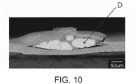
- the LDH separator of the present invention is intentionally provided with a dendrite buffer layer, inside the separator, that has a configuration in a manner such as above (i) to (iii) to allow the zinc dendrites to grow, and the deposition and growth of zinc dendrites D can be confined only in the dendrite buffer layer, for example, shown in FIG. 10 , resulting in prevention or significant delay of the penetration of the dendrites through the separator, and thereby more effectively blocking of the short circuit caused by the zinc dendrites.
- the LDH separator of the present invention has excellent flexibility and strength, as well as a desired ionic conductivity based on the hydroxide ionic conductivity of the LDH.
- the flexibility and strength are caused by those of the polymeric porous substrate itself of the LDH separator.
- the LDH separator is densified in such a manner that the pores of the porous polymer substrate are sufficiently filled with the LDH, thereby high rigidity and low ductility caused by the LDH, which is ceramic material, can be balanced with or reduced by high flexibility and high strength of the porous polymeric substrate.
- the dendrite buffer layer is (i) a pore-rich internal porous layer 10b in the porous substrate, the internal porous layer being free from the LDH or deficient in the LDH as the LDH separator 10 shown in FIG. 1 .
- the LDH separator 10 of the present embodiment includes a pair of LDH separator bodies 10a including the porous substrate and the LDH, and an internal porous layer 10b interposed between the LDH separator bodies 10a.
- the internal porous layer 10b consists of a porous substrate or includes a porous substrate and a reduced amount or density of the LDH.
- the LDH separator bodies 10a may have the same configuration as the conventional LDH separators disclosed in PTLs 1 to 3, and thus can exhibit the same preventive advantage to short circuit caused by dendrites as the conventional LDH separator. However, a further improvement is desired as described above.
- the internal porous layer 10b that has pore-rich portions of the porous substrate and is free from or deficient in the LDH is interposed between the pair of LDH separator bodies10a; hence, zinc dendrites are preferentially deposited and grown in the pores not filled with the LDH of the porous substrate, and the deposition and growth of zinc dendrite are confined only within the internal porous layer 10b, resulting in blocking or significantly delaying the penetration of the dendrites through the separator.
- the LDH separator 10 of the present embodiment can be manufactured by depositing the LDH such that a single sheet of the porous substrate has higher density at two sides and low density in a central region across the thickness. This deposition process can be carried out through, for example, immersing the porous substrate in a solvent such as ethanol immediately before dip coating the porous substrate with alumina/titania mixed sol, and blocking impregnation of the mixed sol into the central region across the thickness of the porous substrate.
- the internal porous layer 10b has a thickness of preferably 0.5 mm or less, more preferably 0.3 mm or less, further more preferably 0.1 mm or less, particularly more preferably 0.05 mm or less, most preferably 0.01 mm or less. Although a larger thickness of the internal porous layer 10b is preferred to reduce the dendrite growth, a smaller thickness is preferred in the application to batteries because the electrical resistance increases with the thickness of the internal porous layer 10b.
- the dendrite buffer layer is (ii) a releasable interfacial layer 10b' at which two adjacent layers composing part of the LDH separator are in releasable contact with each other, like the LDH separator 10' shown in FIG. 2 .
- the LDH separator 10' of the present embodiment comprises a pair of LDH separator bodies 10a including the porous substrate and the LDH, and a releasable interfacial layer 10b' in releasable contact with the pair of LDH separator bodies 10a.
- two layers are in releasable contact with each other indicates that the two layers are fully or partially in contact with each other, and the contact area of the two layers can be reduced (e.g., one layer can be at least partially away from the other layer) along with the deposition and growth of zinc dendrites at the interface between the two layers.
- the LDH separator bodies 10a may have the same configuration as the conventional LDH separators as disclosed in PTLs 1 to 3, and thus can exhibit the same preventive advantage to short circuit caused by dendrites as the conventional LDH separators. However, a further improvement is desired as described above.
- the releasable interfacial layer 10b' is provided that releasably contacts with the pair of LDH separator bodies 10a, the zinc dendrites are preferentially deposited and grown on the releasable interfacial layer 10b', and the deposition and growth of zinc dendrites while expanding the releasable interfacial layer 10b' are confined only within the releasable interfacial layer 10b', thereby the penetration of the dendrites through the separator can be prevented or significantly delayed.
- the LDH separator 10' of the present embodiment can be manufactured by stacking a pair of LDH separator bodies 10a.
- the stack of the LDH separator bodies 10a is preferably pressed to densify during or after the stacking process.
- the press of the stack may be performed by any process, such as roll pressing, uniaxial pressing, and CIP (cold isostatic pressing), preferably roll pressing.
- the stack may be pressed while being heated to soften the polymeric porous substrate, such that the pores of the porous substrate can be sufficiently filled with the LDH.
- the temperature to sufficiently soften the substrate is preferably 60 °C or higher in the case of, for example, polypropylene.
- the dendrite buffer layer is (iii) an inner space layer 10b" (without the LDH and the porous substrate), like the LDH separator 10" shown in FIG. 3 , the inner space layer being formed such that two adjacent layers constituting a part of the LDH separator are disposed apart from each other.
- the LDH separator 10" of the present embodiment includes a pair of LDH separator bodies 10a including the porous substrate and the LDH, and the inner space layer 10b" (without the LDH and the porous substrate) interposed between the pair of LDH separator bodies 10a.
- the LDH separator bodies 10a may have the same configuration as the conventional LDH separators as disclosed in PTLs 1 to 3, and thus can exhibit the same preventive advantage to short circuit caused by dendrites as the conventional LDH separators. However, a further improvement is desired as described above.
- the inner space layer 10b" without the porous substrate and the LDH is provided between the pair of LDH separator bodies 10a, zinc dendrites are preferentially deposited and grown in the inner space layer 10b", and the deposition and growth of zinc dendrites are confined only within the internal porous layer 10b", thereby the penetration of the dendrites through the separator can be prevented or significantly delayed.
- the LDH separator 10" of the present embodiment can be manufactured by disposing a pair of LDH separator bodies 10a apart from each other.
- a spacer may be interposed between the pair of LDH separator bodies 10a.
- the spacer desirably has low electrical resistance to avoid to be resistant in the separator. Examples of low-resistance spacers include conductive materials and porous substrates through which an aqueous alkaline solution can flow (i.e., having communication paths across the thickness). Also, the spacer is preferably thinner for the same reason.
- Each of LDH separator bodies 10a is preferably pressed to densify prior to disposing as described above.
- This pressing may be performed by any procedure, such as roll pressing, uniaxial pressure pressing, and CIP (cold isostatic pressing), preferably roll pressing.
- This pressing preferably involves heating of the composite material to soften the polymeric porous substrate and thereby to sufficiently plug the pores in the porous substrate with the LDH.
- the heating temperature required for enough softening is preferably 60 °C or higher in the case that the polymer is polypropylene.
- the inner space layer 10b" has a thickness of preferably 1 mm or less, more preferably 0.5 mm or less, further more preferably 0.1 mm or less, particularly more preferably 0.05 mm or less, most preferably 0.01 mm or less.
- the inner space layer 10b" has any lower limit of the thickness, because a small space is merely enough for the inner space layer 10b" and the thickness is preferably as small as possible in the case of incorporation into batteries (in particular, small batteries).
- the LDH separator includes a layered double hydroxide (LDH), and can isolate a positive electrode plate from a negative electrode plate and ensures hydroxide ionic conductivity therebetween in a secondary zinc battery.
- the LDH separator functions as a hydroxide ionic conductive separator.
- Preferred LDH separator has gas-impermeability and/or water-impermeability. In other words, the LDH separator is preferably densified to an extent that exhibits gas-impermeability and/or water-impermeability.
- phrases "having gas-impermeability" throughout the specification indicates that no bubbling of helium gas is observed at one side of a sample when helium gas is brought into contact with the other side in water at a differential pressure of 50662.5 Pa (0.5 atm) across the thickness as described in PTLs 2 and 3.
- the phrase “having water-impermeability” throughout the specification indicates that water in contact with one side of the sample does not permeate to the other side as described in PTLs 2 and 3.
- the LDH separator having gas-impermeability and/or water-impermeability indicates having high density to an extent that no gas or no water permeates, and not being a porous membrane or any other porous material that has gas-permeability or water-permeability.
- the LDH separator can selectively permeate only hydroxide ions due to its hydroxide ionic conductivity, and can serve as a battery separator.
- the LDH separator thereby has a physical configuration that prevents penetration of zinc dendrites generated during a charge mode through the separator, resulting in prevention of short circuit between positive and negative electrodes. Since the LDH separator has hydroxide ionic conductivity, the ionic conductivity allows a necessary amount of hydroxide ions to efficiently move between the positive electrode plate and the negative electrode plate, and thereby charge/discharge reaction can be achieved on the positive electrode plate and the negative electrode plate.
- the LDH separator has a helium permeability per unit area of 3.0 cm/min ⁇ atm or less, preferably 2.0 cm/min ⁇ atm or less, more preferably 1.0 cm/min ⁇ atm or less with 1 atm corresponding to 101325 Pa.
- a separator having a helium permeability of 3.0 cm/min ⁇ atm or less can remarkably restrain the permeation of Zn (typically, the permeation of zinc ions or zincate ions) in the electrolytic solution.
- Zn typically, the permeation of zinc ions or zincate ions
- the helium permeability is measured through the steps of: supplying helium gas to one side of the separator to allow the helium gas to permeate into the separator; and calculating the helium permeability to evaluate the density of the hydroxide ion conductive separator.
- the helium permeability is calculated from the expression of F/(P ⁇ S) where F is the volume of permeated helium gas per unit time, P is the differential pressure applied to the separator when helium gas permeates through, and S is the area of the membrane through which helium gas permeates. Evaluation of the permeability of helium gas in this manner can extremely precisely determine the density.
- H 2 gas is suitable for this evaluation because the helium gas has the smallest constitutional unit among various atoms or molecules which can constitute the gas and its reactivity is extremely low. That is, helium does not form a molecule, and helium gas is present in the atomic form.
- hydrogen gas is present in the molecular form (H 2 )
- atomic helium is smaller than molecular H 2 in a gaseous state. Basically, H 2 gas is combustible and dangerous.
- the density can be precisely and readily evaluated regardless of differences in sample size and measurement condition. Thus, whether the separator has sufficiently high density suitable for separators of secondary zinc batteries can be evaluated readily, safely and effectively.
- the helium permeability can be preferably measured in accordance with the procedure shown in Evaluation 5 in Examples described later.
- the pores (except for the dendrite buffer layer) in the porous substrate are filled with the LDH, preferably completely filled with the LDH.
- the LDH is composed of a plurality of basic hydroxide layers and intermediate layers interposed between these basic hydroxide layers.
- the basic hydroxide layers are each mainly composed of metallic elements (typically metallic ions) and OH groups.
- the intermediate layers of the LDH are composed of anions and H 2 O.
- the anions are monovalent or multivalent anions, preferably monovalent or divalent ions.
- the anions in the LDH preferably include OH - and/or CO 3 2- .
- the LDH has high ionic conductivity based on its inherent properties.
- the LDH is known to typically have the fundamental formula: M 2+ 1-x M 3+ x (OH) 2 A n- x/n ⁇ mH 2 O (wherein, M 2+ is a divalent cation, M 3+ is a trivalent cation, A n- is n-valent anion, n is an integer of 1 or more, x is 0.1 to 0.4, and m is 0 or more).
- M 2+ may be any divalent cation, and includes, preferably Mg 2+ , Ca 2+ and Zn 2+ , more preferably Mg 2+ .
- M 3+ may be any trivalent cation, and includes, preferably Al 3+ and Cr 3+ , more preferably Al 3+ .
- a n- may be any anion, and preferably includes OH - and CO 3 2- . Accordingly, it is preferred that M 2+ includes Mg 2+ , M 3+ includes Al 3+ , and An - includes OH - and/or CO 3 2- in the above fundamental formula.
- n is an integer of 1 or more, preferably 1 or 2.
- x is 0.1 to 0.4, preferably 0.2 to 0.35.
- m is an any molar number of water, and is a real number of 0 or more, typically more than 0 or 1 or more.
- the above fundamental formula merely represents "a fundamental composition" typically illustrated for the LDH, and constituent ions can be appropriately replaced.
- part or the whole of M 3+ may be replaced with a tetravalent or higher valence cation, where the coefficient x/n of the anion A n- may be appropriately varied in the above fundamental formula.
- the basic hydroxide layers of LDH may be composed of Ni, Ti, OH groups and optional incidental impurities.
- the intermediate layers of LDH are composed of anions and H 2 O as described above.
- the alternately stacked structure itself of basic hydroxide layers and intermediate layers is basically the same as the commonly known alternately stacked structure of LDH
- the LDH of the embodiment which is composed of the basic hydroxide layers mainly having Ni, Ti and OH groups of LDH, can exhibit high alkaline resistance.
- no element for example, Al
- the LDH of the embodiment can also exhibit high ionic conductivity suitable for separators for alkaline secondary batteries.
- Ni in the LDH can have the form of nickel ions. Although nickel ions in the LDH are typically believed to be Ni 2+ , they may be present in any other valence, for example, Ni 3+ .
- Ti in the LDH can have the form of titanium ions. Although titanium ions in the LDH are typically believed to be Ti 4+ , they may be present in any other valence, for example, Ti 3+ .
- Each of the incidental impurities is any element which may be inevitably mixed in a manufacturing process, and it may be mixed into the LDH from, for example, a raw material or a substrate. As described above, it is impractical or impossible to strictly specify the LDH with a general formula since valences of Ni and Ti are not necessarily confirmed.
- the fundamental composition of the corresponding LDH can be represented by the general formula: Ni 2+ 1-x Ti 4+ x (OH) 2 A n- 2x/n ⁇ mH 2 O, wherein A n- is an n-valent anion, n is an integer of 1 or more, preferably 1 or 2, x is above 0 to below 1, preferably 0.01 to 0.5, and m is a real number of 0 or more, typically a real number above 0 or 1 or more.
- the general formula indicates merely the "fundamental composition", and it may be replaced with other elements or ions (including elements with other valences of the same element, or elements or ions that may be unavoidably mixed in the manufacturing process) to such an extent that the elements such as Ni 2+ , and Ti 4+ do not impair the basic properties of LDH.
- the basic hydroxide layers of LDH comprise Ni, Al, Ti and OH groups.
- the intermediate layers are composed of anions and H 2 O as described above.
- the alternately stacked structure itself of basic hydroxide layers and intermediate layers is basically the same as the generally known alternately stacked structure of LDH
- the LDH of the embodiment, in which the basic hydroxide layers of the LDH are composed of predetermined elements and/or ions including Ni, Al, Ti and OH groups of LDH can exhibit high alkaline resistance.
- Al which has been considered to be readily dissolved in an alkaline solution, is hard to elute into the alkaline solution due to some interaction with Ni and Ti.
- the LDH of the embodiment can also exhibit high ionic conductivity suitable for separators for alkaline secondary batteries.
- Ni in the LDH can have the form of nickel ions. Although nickel ions in the LDH are typically believed to be Ni 2+ , they may be present in any other valence, for example, Ni 3+ .
- Al in the LDH can have the form of aluminum ions. Although aluminum ions in the LDH are typically believed to be Al 3+ , they may be present in any other valence.
- Ti in the LDH can have the form of titanium ions. Although titanium ions in the LDH are typically believed to be Ti 4+ , they may be present in any other valence, for example, Ti 3+ .
- the basic hydroxide layers may contain other elements or ions as long as they contain Ni, Al, Ti and OH groups.
- the basic hydroxide layers preferably contain Ni, Al, Ti and OH groups as main constituent elements. That is, it is preferred that the basic hydroxide layers are mainly composed of Ni, Al, Ti and OH groups. Accordingly, the basic hydroxide layers are typically composed of Ni, Al, Ti, OH groups and optional incidental impurities.
- Each of the incidental impurities is any element which may be inevitably mixed in a manufacturing process, and it may be mixed into the LDH from, for example, a raw material or a substrate.
- the fundamental composition of the corresponding LDH can be represented by the general formula: Ni 2+ 1-x-y Al 3+ x Ti 4+ y (OH) 2 A n- (x+2y)/n ⁇ mH 2 O, wherein A n- is an n-valent anion, n is an integer of 1 or more, preferably 1 or 2, x is above 0 to below 1, preferably 0.01 to 0.5, y is above 0 to below 1, preferably 0.01 to 0.5, x+y is above 0 to below 1, and m is a real number of 0 or more, typically a real number of above 0 or 1 or more.
- the general formula indicates merely the "fundamental composition", and it may be replaced with other elements or ions (including elements with other valences of the same element, or elements or ions that may be unavoidably mixed in the manufacturing process) to such an extent that the elements such as Ni 2+ , Al 3+ and Ti 4+ do not impair the basic properties of LDH.
- the LDH separator comprises the LDH and the porous substrate (typically consists of the porous substrate and the LDH), and the LDH plugs the pores in the porous substrate such that the LDH separator exhibits hydroxide ionic conductivity and gas-impermeability (thus, so as to serve as a LDH separator exhibiting hydroxide ionic conductivity).
- the LDH is preferably embedded over the entire thickness of the porous substrate other than the dendrite buffer layer (For example, the LDH preferably plugs most or all pores inside the porous substrate other than the dendrite buffer layer).
- the LDH separator has an overall thickness (a thickness including the dendrite buffer layer) of preferably 5 ⁇ m to 5 mm, more preferably 5 ⁇ m to 1 mm, further more preferably 5 ⁇ m to 0.5 mm, particularly more preferably 5 ⁇ m to 0.3 mm.
- the porous substrate is composed of a polymeric material.
- the polymeric porous substrate has the following advantages; (1) high flexibility (hard to crack even if thinned), (2) high porosity, (3) high conductivity (small thickness with high porosity), and (4) good manufacturability and handling ability.
- the polymeric porous substrate has a further advantage; (5) readily folding and sealing the LDH separator including the porous substrate composed of the polymeric material based on the advantage (1): high flexibility.
- Preferred examples of the polymeric material include polystyrene, poly(ether sulfone), polypropylene, epoxy resin, poly(phenylene sulfide), fluorocarbon resin (tetra-fluorinated resin such as PTFE), cellulose, nylon, polyethylene and any combination thereof.
- More preferred examples include polystyrene, poly(ether sulfone), polypropylene, epoxy resin, poly(phenylene sulfide), fluorocarbon resin (tetra-fluorinated resin such as PTFE), nylon, polyethylene and any combination thereof from the viewpoint of a thermoplastic resin suitable for hot pressing. All the various preferred materials described above have alkali resistance to be resistant to the electrolytic solution of batteries. More preferred polymeric materials are polyolefins, such as polypropylene and polyethylene, most preferred are polypropylene and polyethylene from the viewpoint of excellent hot-water resistance, acid resistance and alkali resistance, and low material cost.
- the LDH layer is particularly preferably embedded over the entire thickness of the porous substrate (for example, most pores or substantially all pores inside the porous substrate are filled with the LDH).
- a polymeric microporous membrane commercially available can be preferably used as such a polymeric porous substrate.
- the dendrite buffer layer may be produced by the process described above, and a portion of the LDH separator other than the dendrite buffer layer or the LDH separator body 20a can be produced by any process, preferably with appropriate modification of various conditions in known methods (e.g., see PTLs 1 to 3) for producing the LDH-containing functional layer and the composite material (that is, the LDH separator).
- the LDH containing functional layer and the composite material can be produced by the Steps of: (1) providing a porous substrate; (2) applying a titanium oxide sol or a mixed sol of alumina and titania onto the porous substrate and then heating the sol to form a titanium oxide layer or an alumina/titania layer; (3) immersing the porous substrate into an aqueous raw material solution containing nickel ions (Ni 2+ ) or magnesium ion (Mg 2+ ) and urea; and (4) hydrothermally treating the porous substrate in the aqueous raw material solution to form the LDH-containing functional layer on the porous substrate and/or in a porous substrate.
- Step (2) forming the titanium oxide layer or the alumina/titania layer on the porous substrate can not only produce a raw material for the LDH, but also serve as a seed of LDH crystalline growth and uniformly form the LDH containing functional layer that is highly densified on the surface of the porous substrate.
- Step (3) the presence of urea raises the pH value by generation of ammonia in the solution through the hydrolysis of urea, and gives the LDH by formation of hydroxide with coexisting metal ions. Also, generation of carbon dioxide in hydrolysis gives the LDH of a carbonate anion type.
- a composite material that is, the LDH separator
- the porous substrate is composed of a polymeric material and the functional layer is embedded over the porous substrate in the thickness direction
- the mixed sol of alumina and titania is produced by applying the mixed sol of alumina and titania to the substrate in Step (2) in such that the mixed sol permeates into all or most area of the interior pores of the substrate.
- most or substantially all pores inside the porous substrate can be embedded with the LDH.
- Examples of preferred application include dip coating and filtration coating. Particularly preferred is dip coating.
- the amount of the deposited mixed sol can be varied by adjusting the number of times of coating such as dip coating.
- the substrate coated with the mixed sol by, for example, dip coating may be dried and then subjected to Steps (3) and (4).
- the LDH separator of the present invention is preferably applied to secondary zinc batteries.
- a secondary zinc battery comprising the LDH separator are provided.
- a typical secondary zinc battery includes a positive electrode, a negative electrode, and an electrolytic solution, and isolates the positive electrode from the negative electrode with the LDH separator therebetween.
- the secondary zinc battery of the present invention may be of any type that includes a zinc negative electrode and an electrolytic solution (typically, an aqueous alkali metal hydroxide solution). Accordingly, examples of the secondary zinc battery include secondary nickel-zinc batteries, secondary silver oxide-zinc batteries, secondary manganese oxide-zinc batteries, secondary zinc-air batteries, and various other secondary alkaline zinc batteries.
- the secondary zinc battery may preferably be a secondary nickel-zinc battery, the positive electrode of which contains nickel hydroxide and/or nickel oxyhydroxide.
- the secondary zinc battery may be a secondary zinc-air battery, the positive electrode of which is an air electrode.
- the LDH separator of the present invention can be used not only in secondary zinc batteries such as nickel-zinc batteries but also in, for example, nickel-hydrogen batteries.
- the LDH separator serves to block a nitride shuttle (movement of nitrate groups between electrodes), which is a factor of the self-discharging in the battery.
- the LDH separator of the present invention can also be applied in, for example, lithium batteries (batteries having a negative electrode composed of lithium metal), lithium ion batteries (batteries having a negative electrode composed of, for example, carbon), or lithium-air batteries.
- the crystalline phase of the LDH layer was measured with an X-ray diffractometer (RINT TTR III manufactured by Rigaku Corporation) at a voltage of 50 kV, a current of 300 mA, and a measuring range of 10° to 70° to give an XRD profile.
- the resultant XRD profile was identified with the diffraction peaks of LDH (hydrotalcite compound) described in JCPDS card NO.35-0964.
- the density was determined to confirm that the LDH separator had density having no gas permeability.
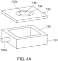
- an open acrylic container 130 and an alumina jig 132 with a shape and dimensions capable of working as a cover of the acrylic container 130 were provided.
- the acrylic container 130 was provided with a gas supply port 130a.
- the alumina jig 132 had an opening 132a having a diameter of 5 mm and a cavity 132b surrounding the opening 132a for placing the sample.
- An epoxy adhesive 134 was applied onto the cavity 132b of the alumina jig 132.
- the LDH separator was placed into the cavity 132b and was bonded to the alumina jig 132 in an air-tight and liquid-tight manner.
- the alumina jig 132 with the LDH separator 136 was then bonded to the upper end of the acrylic container 130 in an air-tight and liquid-tight manner with a silicone adhesive 138 to completely seal the open portion of the acrylic container 130.
- a hermetic container 140 was thereby completed for the measurement.
- the hermetic container 140 for the measurement was placed in a water vessel 142 and the gas supply port 130a of the acrylic container 130 was connected to a pressure gauge 144 and a flow meter 146 so that helium gas was supplied into the acrylic container 130.
- Water 143 was poured in the water vessel 142 to completely submerge the hermetic container 140 for the measurement. At this time, the air-tightness and liquid-tightness were sufficiently kept in the interior of the hermetic container 140 for the measurement, and one surface of the LDH separator 136 was exposed to the internal space of the hermetic container 140 for the measurement while the other surface of the LDH separator 136 was in contact with water in the water vessel 142. In this state, helium gas was introduced into the acrylic container 130 of the hermetic container 140 for the measurement through the gas supply port 130a.
- the pressure gauge 144 and the flow meter 146 were controlled such that the differential pressure between the inside and outside of LDH separator 136 reached 50662.5 Pa (0.5 atm) (that is, the pressure applied to one surface of the helium gas is 0.5 atm higher than the water pressure applied to the other surface) to observe whether or not bubbling of helium gas occurred in water from the LDH separator 136.
- the LDH separator 136 was determined to have high density with no gas permeability.
- a cross-sectional polished surface of the LDH separator was prepared with an ion milling system (IM4000, manufactured by Hitachi High-Technologies Corporation). The microstructure on the cross-sectional polished surface was observed at an acceleration voltage of 10 kV, and each view was photographed at magnifications of 500 folds, 1000 folds, 2500 folds, 5000 folds and 10000 folds with a scanning electron microscope (SEM, JSM-6610LV, manufactured by JEOL Ltd.).
- SEM scanning electron microscope
- a device 210 was assembled as shown in FIG. 5 and an accelerated test was carried out to continuously grow zinc dendrites.
- a rectangular container 212 made of ABS resin was prepared, in which a zinc electrode 214a is separated by 0.5 cm from a copper electrode 214b to face each other.
- the zinc electrode 214a is a metal zinc plate
- the copper electrode 214b is a metal copper plate.
- a LDH separator structure including the LDH separator 216 was constructed, such that an epoxy resin-based adhesive was applied along the outer periphery of the LDH separator, and the LDH separator was bonded to a jig made of ABS resin having an opening at the center.
- the bonded area between the jig and the LDH separator was sufficiently sealed with the adhesive to ensure liquid-tightness.
- the LDH separator structure was then disposed in the container 212 to isolate a first section 215a including the zinc electrode 214a from a second section 215b including the copper electrode 214b, inhibiting liquid communication other than the area of the LDH separator 216.
- three outer edges of the LDH separator structure (or three outer edges of the jig made of ABS resin) were bonded to the inner wall of the container 212 with an epoxy resin adhesive to ensure liquid-tightness.
- the bonded area between the separator structure including the LDH separator 216 and the container 212 was sealed to inhibit the liquid communication.
- aqueous KOH solution as an aqueous alkaline solution 218 was poured into the first section 215a and the second section 215b along with ZnO powders equivalent to saturated solubility.
- the zinc electrode 214a and the copper electrode 214b were connected to a negative terminal and a positive terminal of the constant-current power supply, respectively, and a voltmeter was also connected in parallel with the constant-current power supply.
- the liquid level of the aqueous alkaline solution 218 was determined below the height of the LDH separator structure (including the jig) such that the entire area of the LDH separator 216 in both the first section 215a and the second section 215b was immersed in the aqueous alkaline solution 218.
- a constant current of 20 mA/cm 2 was continuously applied between the zinc electrode 214a and the copper electrode 214b for up to 200 hours.
- the voltage between the zinc electrode 214a and the copper electrode 214b was monitored with a voltmeter to check for short circuit caused by zinc dendrites (a sharp voltage drop) between the zinc electrode 214a and the copper electrode 214b. No short circuit for over 100 hours was determined as "(short circuit) not found", and short circuit within less than 100 hours was determined as "(short circuit) found".
- the helium permeability measurement system 310 shown in FIGS. 3A and 3B was constructed.
- the helium permeability measurement system 310 was configured to supply helium gas from a gas cylinder filled with helium gas to a sample holder 316 through the pressure gauge 312 and a flow meter 314 (digital flow meter), and to discharge the gas by permeating from one side to the other side of the LDH separator 318 held by the sample holder 316.
- the sample holder 316 had a structure including a gas supply port 316a, a sealed space 316b and a gas discharge port 316c, and was assembled as follows: An adhesive 322 was applied along the outer periphery of the LDH separator 318 and bonded to a jig 324 (made of ABS resin) having a central opening. Gaskets or sealing members 326a, 326b made of butyl rubber were disposed at the upper end and the lower end, respectively, of the jig 324, and then the outer sides of the members 326a, 326b were held with supporting members 328a, 328b (made of PTFE) each including a flange having an opening.
- the sealed space 316b was partitioned by the LDH separator 318, the jig 324, the sealing member 326a, and the supporting member 328a.
- the supporting members 328a and 328b were tightly fastened to each other with fastening means 330 with screws not to cause leakage of helium gas from portions other than the gas discharge port 316c.
- a gas supply pipe 334 was connected to the gas supply port 316a of the sample holder 316 assembled as above through a joint 332.
- Helium gas was then supplied to the helium permeability measurement system 310 via the gas supply pipe 334, and the gas was permeated through the LDH separator 318 held in the sample holder 316. A gas supply pressure and a flow rate were then monitored with a pressure gauge 312 and a flow meter 314. After permeation of helium gas for one to thirty minutes, the helium permeability was calculated.
- the helium permeability was calculated from the expression of F/(P ⁇ S) where F (cm 3 /min) was the volume of permeated helium gas per unit time, P (atm) was the differential pressure applied to the LDH separator when helium gas permeated through, and S (cm 2 ) was the area of the membrane through which helium gas permeates.
- the permeation rate F (cm 3 /min) of helium gas was read directly from the flow meter 314.
- the gauge pressure read from the pressure gauge 312 was used for the differential pressure P.
- Helium gas was supplied such that the differential pressure P was within the range of 5066.25 to 91192.5 Pa (0.05 to 0.90 atm with 1 atm corresponding to 101325 Pa).
- a commercially available polypropylene porous substrate having a porosity of 60%, a mean pore size of 0.05 ⁇ m, and a thickness of 20 ⁇ m was cut out into a size of 2.0 cm ⁇ 2.0 cm.
- An amorphous alumina solution (AI-ML15, manufactured by Taki Chemical Co., Ltd.) and a titanium oxide sol solution (M6, manufactured by Taki Chemical Co., Ltd.) were mixed at Ti/AI molar ratio of 2 to yield a mixed sol.
- the substrate prepared in Process (1) was immersed in ethanol for one minute, and then immediately transferred into the mixed sol before being dried.
- the mixed sol was applied onto the substrate by dip coating. In dip coating, the substrate was immersed in 100 mL of the mixed sol, pulled up vertically and dried in a dryer at 90°C for five minutes.
- Nickel nitrate hexahydrate Ni(NO 3 ) 2 ⁇ 6H 2 O, manufactured by Kanto Chemical Co., Inc.
- urea ((NH 2 ) 2 CO, manufactured by Sigma-Aldrich Corporation) were provided as raw materials.
- Nickel nitrate hexahydrate was weighed to be 0.015mol/L and placed in a beaker. Ion-exchanged water was added into a total volume of 75 mL. After stirring the solution, the urea weighed at a urea/NO 3 - molar ratio of 16 was added, and further stirred to give an aqueous raw material solution.
- the aqueous raw material solution and the dip-coated substrate were encapsulated into a Teflon TM autoclave (the internal volume: 100 mL, covered with stainless steel jacket).
- the substrate was horizontally fixed away from the bottom of the Teflon TM autoclave such that the solution was in contact with the two surfaces of the substrate.
- a LDH was then formed on the surface and the interior of the substrate by a hydrothermal treatment at a temperature of 120°C for 24 hour. After a predetermined period, the substrate was removed from the autoclave, washed with ion-exchanged water, and dried at 70°C for ten hours to form the LDH in the pores of porous substrate and give the LDH separator.
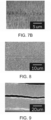
- the resultant LDH separator was evaluated in accordance with Evaluations 1 to 5. As a result of Evaluation 1, this LDH separator was identified as LDH (hydrotalcite compound). As a result of Evaluation 2, bubbling of helium gas was not observed in this LDH separator. Evaluation 3, as shown in FIGS. 7A and 7B , indicated that this LDH separator had an internal porous layer being free from or deficient in the LDH between a pair of LDH separator bodies. The results of Evaluations 4 and 5 are shown in Table 1.
- a LDH separator layer including no internal porous layer was produced as in Example 1 except that the mixed sol was applied onto the substrate by dip coating without immersion in ethanol in Process (2). Two sheets of the LDH separator layer produced as above were stacked. The stack was disposed between a pair of PET films (Lumirror TM manufactured by Toray Industries, Inc., a thickness of 40 ⁇ m), and roll-pressed at a rotation rate of 3 mm/s, at a roller temperature of 100 °C, and with a gap between rollers of 150 ⁇ m to give a LDH separator including a releasable interfacial layer. The resultant LDH separator was evaluated as in Example 1.
- PET films Limirror TM manufactured by Toray Industries, Inc., a thickness of 40 ⁇ m
- the resultant LDH separator was evaluated as in Example 1.
- FIG. 10 illustrates a cross-sectional SEM image of the LDH separator photographed after the test of short circuit caused by dendrites in Evaluation 4, where the symbol D indicates a dendrite in the image.
- a LDH separator layer including no internal porous layer was produced as in Example 1 except that the mixed sol was applied onto the substrate by dip coating without immersion in ethanol in Process (2). Two sheets of the LDH separator layer produced as above were disposed to face each other with a gap of about 5 ⁇ m to give a LDH separator including an internal gap layer.
- the resultant LDH separator was evaluated as in Example 1. As a result of Evaluation 1, this LDH separator was identified as LDH (hydrotalcite compound). As a result of Evaluation 2, bubbling of helium gas was not observed in this LDH separator. Evaluation 3, as shown in FIG. 9 , indicates that this LDH separator had an internal gap layer between a pair of LDH separator bodies. The internal gap layer was free from the LDH and the porous substrate between two LDH separator bodies. The results of Evaluations 4 and 5 are shown in Table 1.
- a LDH separator layer including no internal porous layer was produced as in Example 1 except that the mixed sol was applied onto the substrate by dip coating without immersion in ethanol in Process (2).
- the resultant LDH separator was evaluated as in Example 1.
- this LDH separator is identified as LDH (hydrotalcite compound).
- bubbling of helium gas was not observed in this LDH separator.
- Evaluation 3 indicated that this LDH separator was composed only of a single LDH layer, and no dendrite buffer layer was found.
- the results of Evaluations 4 and 5 are shown in Table 1.
- a LDH separator was produced and evaluated as in Example 1 except for the following conditions a) to c).
- this LDH separator was identified as LDH (hydrotalcite compound). As a result of Evaluation 2, bubbling of helium gas was not observed in this LDH separator. Evaluation 3 indicated that this LDH separator had an internal porous layer being free from or deficient in the LDH between a pair of LDH separator bodies, similar to Example 1. The results of Evaluations 4 and 5 are shown in Table 1.
- a LDH separator layer including no internal porous layer was produced as in Example 1 except for the following conditions a) to d).
- LDH separator layer Two sheets of the LDH separator layer produced as above was stacked.
- the stack was disposed between a pair of PET films (Lumirror TM manufactured by Toray Industries, Inc., a thickness of 40 ⁇ m), and roll-pressed at a rotation rate of 3 mm/s, at a roller temperature of 100 °C, and with a gap between rollers of 150 ⁇ m to give a LDH separator including a releasable interfacial layer.
- the resultant LDH separator was evaluated as in Example 1. As a result of Evaluation 1, this LDH separator was identified as LDH (hydrotalcite compound). As a result of Evaluation 2, bubbling of helium gas was not observed in this LDH separator.
- Evaluation 3 indicated this LDH separator had the releasable interfacial layer, between a pair of LDH separator bodies, thereby two LDH separator bodies were in releasable contact with each other, similar to Example 2.
- the results of Evaluations 4 and 5 are shown in Table 1.
- a LDH separator layer including no internal porous layer was produced as in Example 1 except for the following conditions a) to d).
- a LDH separator layer including no internal porous layer was produced as in Example 1 except for the following conditions a) to c).
- this LDH separator was identified as LDH (hydrotalcite compound). As a result of Evaluation 2, bubbling of helium gas was not observed in this LDH separator. Evaluation 3 indicated that this LDH separator was composed only of a single LDH layer, and no dendrite buffer layer was found. The results of Evaluations 4 and 5 are shown in Table 1.
Landscapes
- Chemical & Material Sciences (AREA)
- Chemical Kinetics & Catalysis (AREA)
- Electrochemistry (AREA)
- General Chemical & Material Sciences (AREA)
- Engineering & Computer Science (AREA)
- Manufacturing & Machinery (AREA)
- Inorganic Chemistry (AREA)
- Composite Materials (AREA)
- Materials Engineering (AREA)
- Cell Separators (AREA)
Claims (8)
- Geschichteter Doppelhydroxidseparator (LDH-Separator) (10, 10', 10") für Zink-Sekundärbatterien, der ein poröses Substrat, das aus einem Polymermaterial hergestellt ist, und ein LDH, das Poren im porösen Substrat abdichtet, umfasst, wobei der LDH-Separator (10, 10', 10") in seinem Inneren eine Dendritenpufferschicht aufweist und die Dendritenpufferschicht mindestens eine ist, die aus der Gruppe gewählt ist, die aus Folgendem besteht:(i) einer porenreichen internen porösen Schicht (10b) im porösen Substrat, wobei die interne poröse Schicht (10b) frei vom LDH oder LDH-arm ist;(ii) einer lösbaren Grenzflächenschicht (10b'), die durch zwei benachbarte Schichten geschaffen wird, die einen Abschnitt des LDH-Separators (10, 10', 10") bilden und in lösbarem Kontakt miteinander sind; und(iii) einer internen Lückenschicht (10b"), die frei von dem LDH und dem porösen Substrat ist und durch zwei benachbarte Schichten geschaffen wird, die einen Abschnitt des LDH-Separators (10, 10, 10") bilden und voneinander getrennt gebildet sind; wobeider LDH-Separator (10, 10', 10") eine Helium-Durchlässigkeit pro Flächeneinheit von 3,0 cm/atm·min oder weniger aufweist, die durch Aufbringen eines Differenzdrucks im Bereich von 0,05 bis 0,90 atm auf den LDH-Separator (318) bestimmt wird, wobei 1 atm 101325 Pa entspricht.
- LDH-Separator (10, 10', 10") nach Anspruch 1, wobei das LDH über die gesamte Dicke des porösen Substrats außer der Dendritenpufferschicht aufgenommen ist.
- LDH-Separator (10, 10', 10") nach Anspruch 1 oder 2, wobei die Dendritenpufferschicht (i) eine porenreiche interne poröse Schicht (10b) im porösen Substrat ist und die interne poröse Schicht frei vom LDH oder LDH-arm ist.
- LDH-Separator (10, 10', 10") nach Anspruch 1 oder 2, wobei die Dendritenpufferschicht (ii) eine lösbare Grenzflächenschicht (10b') ist, die durch zwei benachbarte Schichten geschaffen wird, die einen Abschnitt des LDH-Separators (10, 10', 10") bilden und in lösbarem Kontakt miteinander sind.
- LDH-Separator (10, 10', 10") nach Anspruch 1 oder 2, wobei die Dendritenpufferschicht (iii) eine interne Lückenschicht (10b") ist, die frei von dem LDH und dem porösen Substrat ist und durch zwei benachbarte Schichten geschaffen wird, die einen Abschnitt des LDH-Separators (10, 10', 10") bilden und getrennt voneinander gebildet sind.
- LDH-Separator (10, 10', 10") nach einem der Ansprüche 1 bis 5, wobei das Polymermaterial aus der Gruppe gewählt ist, die aus Polystyrol, Poly(Ethersulfon), Polypropylen, Epoxidharz, Poly(Phenylensulfid), Fluorkohlenwasserstoffharz, Zellulose, Nylon und Polyethylen besteht.
- LDH-Separator (10, 10', 10") nach einem der Ansprüche 1 bis 6, der aus dem porösen Substrat und dem LDH besteht.
- Zink-Sekundärbatterie, die den LDH-Separator (10, 10', 10") nach einem der Ansprüche 1 bis 7 umfasst.
Applications Claiming Priority (2)
| Application Number | Priority Date | Filing Date | Title |
|---|---|---|---|
| JP2017251005 | 2017-12-27 | ||
| PCT/JP2018/047686 WO2019131688A1 (ja) | 2017-12-27 | 2018-12-25 | Ldhセパレータ及び亜鉛二次電池 |
Publications (4)
| Publication Number | Publication Date |
|---|---|
| EP3534432A1 EP3534432A1 (de) | 2019-09-04 |
| EP3534432A8 EP3534432A8 (de) | 2019-11-20 |
| EP3534432A4 EP3534432A4 (de) | 2020-08-05 |
| EP3534432B1 true EP3534432B1 (de) | 2023-10-25 |
Family
ID=67067490
Family Applications (1)
| Application Number | Title | Priority Date | Filing Date |
|---|---|---|---|
| EP18880068.4A Active EP3534432B1 (de) | 2017-12-27 | 2018-12-25 | Ldh-separator und zinksekundärbatterie |
Country Status (6)
| Country | Link |
|---|---|
| US (1) | US11335973B2 (de) |
| EP (1) | EP3534432B1 (de) |
| JP (1) | JP6684964B2 (de) |
| CN (1) | CN111615759B (de) |
| TW (1) | TWI678833B (de) |
| WO (1) | WO2019131688A1 (de) |
Families Citing this family (7)
| Publication number | Priority date | Publication date | Assignee | Title |
|---|---|---|---|---|
| US11024877B2 (en) * | 2018-12-04 | 2021-06-01 | TeraWatt Technology Inc. | Anode-free solid-state battery cells with anti-dendrite and interface adhesion controlled functional layers |
| JP7441308B2 (ja) * | 2020-05-11 | 2024-02-29 | 日本碍子株式会社 | Ldhセパレータ及び亜鉛二次電池 |
| DE112021003617T5 (de) | 2020-12-01 | 2023-04-27 | Ngk Insulators, Ltd. | Separator mit ldh-ähnlicher verbindung und zink-sekundärbatterie |
| WO2022118504A1 (ja) * | 2020-12-01 | 2022-06-09 | 日本碍子株式会社 | Ldh様化合物セパレータ及び亜鉛二次電池 |
| CN114497886B (zh) * | 2022-01-25 | 2024-09-03 | 中山大学 | 二维水滑石分子刷改性pp隔膜的制备方法和应用 |
| WO2024202370A1 (ja) * | 2023-03-27 | 2024-10-03 | 日本碍子株式会社 | Ldhセパレータ及び亜鉛二次電池 |
| CN119725980B (zh) * | 2024-12-19 | 2025-10-14 | 大连理工大学 | 一种不同价态金属阳离子缺陷的ldh作为锂硫电池功能化隔膜材料的制备方法 |
Family Cites Families (19)
| Publication number | Priority date | Publication date | Assignee | Title |
|---|---|---|---|---|
| JP4303948B2 (ja) * | 2002-12-11 | 2009-07-29 | 榮一 成田 | 層状複水酸化物のデラミネーション方法 |
| CN100568613C (zh) * | 2004-02-06 | 2009-12-09 | 波利普拉斯电池有限公司 | 具有非水中间层构造的受保护的活性金属电极和电池组电池结构 |
| JP5187797B2 (ja) * | 2005-07-25 | 2013-04-24 | 独立行政法人物質・材料研究機構 | 層状複水酸化物を剥離する方法、複水酸化物ナノシート、該複合薄膜材料、該製造方法、および、層状複水酸化物薄膜材料の製造方法 |
| WO2008133642A2 (en) * | 2006-10-13 | 2008-11-06 | Ceramatec, Inc. | Advanced metal-air battery having a ceramic membrane electrolyte |
| JP2010050076A (ja) * | 2008-07-03 | 2010-03-04 | Hitachi Chem Co Ltd | 電気化学素子用セパレータ、これを用いたリチウム電池又はリチウムイオン電池、及び電気化学素子用セパレータの製造方法 |
| JP5370682B2 (ja) * | 2010-03-04 | 2013-12-18 | 戸田工業株式会社 | Zn−Mg−Alハイドロタルサイト型粒子粉末及び該Zn−Mg−Alハイドロタルサイト型粒子粉末を含有する樹脂組成物 |
| EP2814104B1 (de) * | 2012-02-06 | 2018-09-26 | NGK Insulators, Ltd. | Zinksekundärzelle |
| US9450224B2 (en) * | 2012-03-28 | 2016-09-20 | Sharp Laboratories Of America, Inc. | Sodium iron(II)-hexacyanoferrate(II) battery electrode and synthesis method |
| WO2014107433A2 (en) * | 2013-01-01 | 2014-07-10 | Massachusetts Institute Of Technology | Multi-layer structures prepared by layer-by-layer assembly |
| JP6292906B2 (ja) * | 2013-02-01 | 2018-03-14 | 株式会社日本触媒 | アニオン伝導性材料及び電池 |
| CN103474609B (zh) * | 2013-09-27 | 2015-12-09 | 中材科技股份有限公司 | 一种叠涂复合锂电池隔膜 |
| JP6244174B2 (ja) * | 2013-11-08 | 2017-12-06 | 株式会社日本触媒 | アニオン伝導膜及び電池 |
| WO2015074037A2 (en) * | 2013-11-18 | 2015-05-21 | California Institute Of Technology | Separator enclosures for electrodes and electrochemical cells |
| WO2016067884A1 (ja) | 2014-10-28 | 2016-05-06 | 日本碍子株式会社 | 層状複水酸化物緻密膜の形成方法 |
| JP6030780B2 (ja) | 2014-11-13 | 2016-11-24 | 日本碍子株式会社 | 水酸化物イオン伝導性セラミックスセパレータを用いた二次電池 |
| WO2016076047A1 (ja) | 2014-11-13 | 2016-05-19 | 日本碍子株式会社 | 亜鉛二次電池に用いられるセパレータ構造体 |
| JP6180063B2 (ja) * | 2015-03-19 | 2017-08-16 | 日本碍子株式会社 | 電池及びその組み立て方法 |
| JP6243583B1 (ja) * | 2016-06-24 | 2017-12-06 | 日本碍子株式会社 | 層状複水酸化物を含む機能層及び複合材料 |
| CN107316967A (zh) * | 2017-06-26 | 2017-11-03 | 上海空间电源研究所 | 一种包含活性夹层的隔膜、其制备方法及用途 |
-
2018
- 2018-12-25 EP EP18880068.4A patent/EP3534432B1/de active Active
- 2018-12-25 JP JP2019512839A patent/JP6684964B2/ja active Active
- 2018-12-25 TW TW107146873A patent/TWI678833B/zh active
- 2018-12-25 CN CN201880004346.5A patent/CN111615759B/zh active Active
- 2018-12-25 WO PCT/JP2018/047686 patent/WO2019131688A1/ja not_active Ceased
-
2019
- 2019-05-23 US US16/420,869 patent/US11335973B2/en active Active
Also Published As
| Publication number | Publication date |
|---|---|
| EP3534432A8 (de) | 2019-11-20 |
| JPWO2019131688A1 (ja) | 2020-01-16 |
| CN111615759B (zh) | 2023-05-16 |
| TW201931643A (zh) | 2019-08-01 |
| TWI678833B (zh) | 2019-12-01 |
| JP6684964B2 (ja) | 2020-04-22 |
| US11335973B2 (en) | 2022-05-17 |
| US20190280272A1 (en) | 2019-09-12 |
| CN111615759A (zh) | 2020-09-01 |
| EP3534432A1 (de) | 2019-09-04 |
| WO2019131688A1 (ja) | 2019-07-04 |
| EP3534432A4 (de) | 2020-08-05 |
Similar Documents
| Publication | Publication Date | Title |
|---|---|---|
| EP3534432B1 (de) | Ldh-separator und zinksekundärbatterie | |
| US11431034B2 (en) | Hydroxide ion conductive separator and zinc secondary battery | |
| US11545719B2 (en) | LDH separator and secondary zinc battery | |
| US11211672B2 (en) | LDH separator and zinc secondary battery | |
| US12191534B2 (en) | LDH separator and zinc secondary battery | |
| JP6997019B2 (ja) | 亜鉛二次電池 | |
| US11158906B2 (en) | LDH separator and zinc secondary battery | |
| US11145935B2 (en) | LDH separator and zinc secondary cell | |
| US11239489B2 (en) | Zinc secondary battery | |
| JP7714410B2 (ja) | Ldhセパレータ及び亜鉛二次電池 | |
| JP7717825B2 (ja) | Ldhセパレータ及びその製造方法、並びに亜鉛二次電池 | |
| US20230207796A1 (en) | Zinc secondary battery | |
| US20230207965A1 (en) | Ldh-like compound separator and zinc secondary battery | |
| US11532855B2 (en) | LDH separator and secondary zinc battery | |
| US12519112B2 (en) | LDH-like compound separator and zinc secondary battery | |
| US20230198095A1 (en) | Ldh-like compound separator and zinc secondary battery | |
| US20230231153A1 (en) | Ldh-like compound separator and secondary zinc battery | |
| JP2024140241A (ja) | Ldhセパレータ及び亜鉛二次電池 | |
| WO2024202370A1 (ja) | Ldhセパレータ及び亜鉛二次電池 | |
| JP2024140384A (ja) | Ldhセパレータ及び亜鉛二次電池 |
Legal Events
| Date | Code | Title | Description |
|---|---|---|---|
| STAA | Information on the status of an ep patent application or granted ep patent |
Free format text: STATUS: UNKNOWN |
|
| STAA | Information on the status of an ep patent application or granted ep patent |
Free format text: STATUS: THE INTERNATIONAL PUBLICATION HAS BEEN MADE |
|
| PUAI | Public reference made under article 153(3) epc to a published international application that has entered the european phase |
Free format text: ORIGINAL CODE: 0009012 |
|
| STAA | Information on the status of an ep patent application or granted ep patent |
Free format text: STATUS: THE APPLICATION HAS BEEN PUBLISHED |
|
| AK | Designated contracting states |
Kind code of ref document: A1 Designated state(s): AL AT BE BG CH CY CZ DE DK EE ES FI FR GB GR HR HU IE IS IT LI LT LU LV MC MK MT NL NO PL PT RO RS SE SI SK SM TR |
|
| AX | Request for extension of the european patent |
Extension state: BA ME |
|
| RIN1 | Information on inventor provided before grant (corrected) |
Inventor name: YOKOYAMA, SHOHEI Inventor name: OKOCHI, SOTA |
|
| STAA | Information on the status of an ep patent application or granted ep patent |
Free format text: STATUS: REQUEST FOR EXAMINATION WAS MADE |
|
| 17P | Request for examination filed |
Effective date: 20200107 |
|
| RBV | Designated contracting states (corrected) |
Designated state(s): AL AT BE BG CH CY CZ DE DK EE ES FI FR GB GR HR HU IE IS IT LI LT LU LV MC MK MT NL NO PL PT RO RS SE SI SK SM TR |
|
| A4 | Supplementary search report drawn up and despatched |
Effective date: 20200708 |
|
| RIC1 | Information provided on ipc code assigned before grant |
Ipc: H01M 10/24 20060101ALI20200702BHEP Ipc: H01M 12/08 20060101ALI20200702BHEP Ipc: H01M 12/06 20060101ALI20200702BHEP Ipc: H01M 10/30 20060101ALI20200702BHEP Ipc: H01M 10/32 20060101ALN20200702BHEP Ipc: H01M 10/42 20060101ALN20200702BHEP Ipc: H01M 4/38 20060101ALI20200702BHEP Ipc: H01M 2/16 20060101AFI20200702BHEP |
|
| DAV | Request for validation of the european patent (deleted) | ||
| DAX | Request for extension of the european patent (deleted) | ||
| REG | Reference to a national code |
Ref country code: DE Ref legal event code: R079 Ref country code: DE Ref legal event code: R079 Ref document number: 602018060156 Country of ref document: DE Free format text: PREVIOUS MAIN CLASS: H01M0002160000 Ipc: H01M0010300000 |
|
| GRAP | Despatch of communication of intention to grant a patent |
Free format text: ORIGINAL CODE: EPIDOSNIGR1 |
|
| STAA | Information on the status of an ep patent application or granted ep patent |
Free format text: STATUS: GRANT OF PATENT IS INTENDED |
|
| RIC1 | Information provided on ipc code assigned before grant |
Ipc: H01M 10/42 20060101ALN20230421BHEP Ipc: H01M 10/32 20060101ALN20230421BHEP Ipc: H01M 50/491 20210101ALI20230421BHEP Ipc: H01M 50/457 20210101ALI20230421BHEP Ipc: H01M 50/451 20210101ALI20230421BHEP Ipc: H01M 50/446 20210101ALI20230421BHEP Ipc: H01M 12/06 20060101ALI20230421BHEP Ipc: H01M 10/24 20060101ALI20230421BHEP Ipc: H01M 4/38 20060101ALI20230421BHEP Ipc: H01M 12/08 20060101ALI20230421BHEP Ipc: H01M 10/30 20060101AFI20230421BHEP |
|
| INTG | Intention to grant announced |
Effective date: 20230526 |
|
| GRAS | Grant fee paid |
Free format text: ORIGINAL CODE: EPIDOSNIGR3 |
|
| GRAA | (expected) grant |
Free format text: ORIGINAL CODE: 0009210 |
|
| STAA | Information on the status of an ep patent application or granted ep patent |
Free format text: STATUS: THE PATENT HAS BEEN GRANTED |
|
| AK | Designated contracting states |
Kind code of ref document: B1 Designated state(s): AL AT BE BG CH CY CZ DE DK EE ES FI FR GB GR HR HU IE IS IT LI LT LU LV MC MK MT NL NO PL PT RO RS SE SI SK SM TR |
|
| REG | Reference to a national code |
Ref country code: GB Ref legal event code: FG4D |
|
| REG | Reference to a national code |
Ref country code: CH Ref legal event code: EP |
|
| REG | Reference to a national code |
Ref country code: DE Ref legal event code: R096 Ref document number: 602018060156 Country of ref document: DE |
|
| REG | Reference to a national code |
Ref country code: IE Ref legal event code: FG4D |
|
| REG | Reference to a national code |
Ref country code: LT Ref legal event code: MG9D |
|
| REG | Reference to a national code |
Ref country code: NL Ref legal event code: MP Effective date: 20231025 |
|
| REG | Reference to a national code |
Ref country code: AT Ref legal event code: MK05 Ref document number: 1625603 Country of ref document: AT Kind code of ref document: T Effective date: 20231025 |
|
| PG25 | Lapsed in a contracting state [announced via postgrant information from national office to epo] |
Ref country code: NL Free format text: LAPSE BECAUSE OF FAILURE TO SUBMIT A TRANSLATION OF THE DESCRIPTION OR TO PAY THE FEE WITHIN THE PRESCRIBED TIME-LIMIT Effective date: 20231025 |
|
| PG25 | Lapsed in a contracting state [announced via postgrant information from national office to epo] |
Ref country code: GR Free format text: LAPSE BECAUSE OF FAILURE TO SUBMIT A TRANSLATION OF THE DESCRIPTION OR TO PAY THE FEE WITHIN THE PRESCRIBED TIME-LIMIT Effective date: 20240126 |
|
| PG25 | Lapsed in a contracting state [announced via postgrant information from national office to epo] |
Ref country code: IS Free format text: LAPSE BECAUSE OF FAILURE TO SUBMIT A TRANSLATION OF THE DESCRIPTION OR TO PAY THE FEE WITHIN THE PRESCRIBED TIME-LIMIT Effective date: 20240225 |
|
| PG25 | Lapsed in a contracting state [announced via postgrant information from national office to epo] |
Ref country code: LT Free format text: LAPSE BECAUSE OF FAILURE TO SUBMIT A TRANSLATION OF THE DESCRIPTION OR TO PAY THE FEE WITHIN THE PRESCRIBED TIME-LIMIT Effective date: 20231025 |
|
| PG25 | Lapsed in a contracting state [announced via postgrant information from national office to epo] |
Ref country code: AT Free format text: LAPSE BECAUSE OF FAILURE TO SUBMIT A TRANSLATION OF THE DESCRIPTION OR TO PAY THE FEE WITHIN THE PRESCRIBED TIME-LIMIT Effective date: 20231025 |
|
| PG25 | Lapsed in a contracting state [announced via postgrant information from national office to epo] |
Ref country code: ES Free format text: LAPSE BECAUSE OF FAILURE TO SUBMIT A TRANSLATION OF THE DESCRIPTION OR TO PAY THE FEE WITHIN THE PRESCRIBED TIME-LIMIT Effective date: 20231025 |
|
| PG25 | Lapsed in a contracting state [announced via postgrant information from national office to epo] |
Ref country code: LT Free format text: LAPSE BECAUSE OF FAILURE TO SUBMIT A TRANSLATION OF THE DESCRIPTION OR TO PAY THE FEE WITHIN THE PRESCRIBED TIME-LIMIT Effective date: 20231025 Ref country code: IS Free format text: LAPSE BECAUSE OF FAILURE TO SUBMIT A TRANSLATION OF THE DESCRIPTION OR TO PAY THE FEE WITHIN THE PRESCRIBED TIME-LIMIT Effective date: 20240225 Ref country code: GR Free format text: LAPSE BECAUSE OF FAILURE TO SUBMIT A TRANSLATION OF THE DESCRIPTION OR TO PAY THE FEE WITHIN THE PRESCRIBED TIME-LIMIT Effective date: 20240126 Ref country code: ES Free format text: LAPSE BECAUSE OF FAILURE TO SUBMIT A TRANSLATION OF THE DESCRIPTION OR TO PAY THE FEE WITHIN THE PRESCRIBED TIME-LIMIT Effective date: 20231025 Ref country code: BG Free format text: LAPSE BECAUSE OF FAILURE TO SUBMIT A TRANSLATION OF THE DESCRIPTION OR TO PAY THE FEE WITHIN THE PRESCRIBED TIME-LIMIT Effective date: 20240125 Ref country code: AT Free format text: LAPSE BECAUSE OF FAILURE TO SUBMIT A TRANSLATION OF THE DESCRIPTION OR TO PAY THE FEE WITHIN THE PRESCRIBED TIME-LIMIT Effective date: 20231025 Ref country code: PT Free format text: LAPSE BECAUSE OF FAILURE TO SUBMIT A TRANSLATION OF THE DESCRIPTION OR TO PAY THE FEE WITHIN THE PRESCRIBED TIME-LIMIT Effective date: 20240226 |
|
| PG25 | Lapsed in a contracting state [announced via postgrant information from national office to epo] |
Ref country code: SE Free format text: LAPSE BECAUSE OF FAILURE TO SUBMIT A TRANSLATION OF THE DESCRIPTION OR TO PAY THE FEE WITHIN THE PRESCRIBED TIME-LIMIT Effective date: 20231025 Ref country code: RS Free format text: LAPSE BECAUSE OF FAILURE TO SUBMIT A TRANSLATION OF THE DESCRIPTION OR TO PAY THE FEE WITHIN THE PRESCRIBED TIME-LIMIT Effective date: 20231025 Ref country code: PL Free format text: LAPSE BECAUSE OF FAILURE TO SUBMIT A TRANSLATION OF THE DESCRIPTION OR TO PAY THE FEE WITHIN THE PRESCRIBED TIME-LIMIT Effective date: 20231025 Ref country code: NO Free format text: LAPSE BECAUSE OF FAILURE TO SUBMIT A TRANSLATION OF THE DESCRIPTION OR TO PAY THE FEE WITHIN THE PRESCRIBED TIME-LIMIT Effective date: 20240125 Ref country code: LV Free format text: LAPSE BECAUSE OF FAILURE TO SUBMIT A TRANSLATION OF THE DESCRIPTION OR TO PAY THE FEE WITHIN THE PRESCRIBED TIME-LIMIT Effective date: 20231025 Ref country code: HR Free format text: LAPSE BECAUSE OF FAILURE TO SUBMIT A TRANSLATION OF THE DESCRIPTION OR TO PAY THE FEE WITHIN THE PRESCRIBED TIME-LIMIT Effective date: 20231025 |
|
| PG25 | Lapsed in a contracting state [announced via postgrant information from national office to epo] |
Ref country code: DK Free format text: LAPSE BECAUSE OF FAILURE TO SUBMIT A TRANSLATION OF THE DESCRIPTION OR TO PAY THE FEE WITHIN THE PRESCRIBED TIME-LIMIT Effective date: 20231025 |
|
| PG25 | Lapsed in a contracting state [announced via postgrant information from national office to epo] |
Ref country code: CZ Free format text: LAPSE BECAUSE OF FAILURE TO SUBMIT A TRANSLATION OF THE DESCRIPTION OR TO PAY THE FEE WITHIN THE PRESCRIBED TIME-LIMIT Effective date: 20231025 |
|
| REG | Reference to a national code |
Ref country code: DE Ref legal event code: R097 Ref document number: 602018060156 Country of ref document: DE |
|
| PG25 | Lapsed in a contracting state [announced via postgrant information from national office to epo] |
Ref country code: SK Free format text: LAPSE BECAUSE OF FAILURE TO SUBMIT A TRANSLATION OF THE DESCRIPTION OR TO PAY THE FEE WITHIN THE PRESCRIBED TIME-LIMIT Effective date: 20231025 |
|
| PG25 | Lapsed in a contracting state [announced via postgrant information from national office to epo] |
Ref country code: SM Free format text: LAPSE BECAUSE OF FAILURE TO SUBMIT A TRANSLATION OF THE DESCRIPTION OR TO PAY THE FEE WITHIN THE PRESCRIBED TIME-LIMIT Effective date: 20231025 Ref country code: SK Free format text: LAPSE BECAUSE OF FAILURE TO SUBMIT A TRANSLATION OF THE DESCRIPTION OR TO PAY THE FEE WITHIN THE PRESCRIBED TIME-LIMIT Effective date: 20231025 Ref country code: RO Free format text: LAPSE BECAUSE OF FAILURE TO SUBMIT A TRANSLATION OF THE DESCRIPTION OR TO PAY THE FEE WITHIN THE PRESCRIBED TIME-LIMIT Effective date: 20231025 Ref country code: IT Free format text: LAPSE BECAUSE OF FAILURE TO SUBMIT A TRANSLATION OF THE DESCRIPTION OR TO PAY THE FEE WITHIN THE PRESCRIBED TIME-LIMIT Effective date: 20231025 Ref country code: EE Free format text: LAPSE BECAUSE OF FAILURE TO SUBMIT A TRANSLATION OF THE DESCRIPTION OR TO PAY THE FEE WITHIN THE PRESCRIBED TIME-LIMIT Effective date: 20231025 Ref country code: DK Free format text: LAPSE BECAUSE OF FAILURE TO SUBMIT A TRANSLATION OF THE DESCRIPTION OR TO PAY THE FEE WITHIN THE PRESCRIBED TIME-LIMIT Effective date: 20231025 Ref country code: CZ Free format text: LAPSE BECAUSE OF FAILURE TO SUBMIT A TRANSLATION OF THE DESCRIPTION OR TO PAY THE FEE WITHIN THE PRESCRIBED TIME-LIMIT Effective date: 20231025 |
|
| REG | Reference to a national code |
Ref country code: CH Ref legal event code: PL |
|
| PG25 | Lapsed in a contracting state [announced via postgrant information from national office to epo] |
Ref country code: LU Free format text: LAPSE BECAUSE OF NON-PAYMENT OF DUE FEES Effective date: 20231225 |
|
| PG25 | Lapsed in a contracting state [announced via postgrant information from national office to epo] |
Ref country code: MC Free format text: LAPSE BECAUSE OF FAILURE TO SUBMIT A TRANSLATION OF THE DESCRIPTION OR TO PAY THE FEE WITHIN THE PRESCRIBED TIME-LIMIT Effective date: 20231025 |
|
| REG | Reference to a national code |
Ref country code: BE Ref legal event code: MM Effective date: 20231231 |
|
| PG25 | Lapsed in a contracting state [announced via postgrant information from national office to epo] |
Ref country code: MC Free format text: LAPSE BECAUSE OF FAILURE TO SUBMIT A TRANSLATION OF THE DESCRIPTION OR TO PAY THE FEE WITHIN THE PRESCRIBED TIME-LIMIT Effective date: 20231025 Ref country code: LU Free format text: LAPSE BECAUSE OF NON-PAYMENT OF DUE FEES Effective date: 20231225 |
|
| PLBE | No opposition filed within time limit |
Free format text: ORIGINAL CODE: 0009261 |
|
| STAA | Information on the status of an ep patent application or granted ep patent |
Free format text: STATUS: NO OPPOSITION FILED WITHIN TIME LIMIT |
|
| GBPC | Gb: european patent ceased through non-payment of renewal fee |
Effective date: 20240125 |
|
| 26N | No opposition filed |
Effective date: 20240726 |
|
| REG | Reference to a national code |
Ref country code: IE Ref legal event code: MM4A |
|
| PG25 | Lapsed in a contracting state [announced via postgrant information from national office to epo] |
Ref country code: IE Free format text: LAPSE BECAUSE OF NON-PAYMENT OF DUE FEES Effective date: 20231225 |
|
| PG25 | Lapsed in a contracting state [announced via postgrant information from national office to epo] |
Ref country code: GB Free format text: LAPSE BECAUSE OF NON-PAYMENT OF DUE FEES Effective date: 20240125 |
|
| PG25 | Lapsed in a contracting state [announced via postgrant information from national office to epo] |
Ref country code: BE Free format text: LAPSE BECAUSE OF NON-PAYMENT OF DUE FEES Effective date: 20231231 |
|
| PG25 | Lapsed in a contracting state [announced via postgrant information from national office to epo] |
Ref country code: FR Free format text: LAPSE BECAUSE OF NON-PAYMENT OF DUE FEES Effective date: 20231225 |
|
| PG25 | Lapsed in a contracting state [announced via postgrant information from national office to epo] |
Ref country code: CH Free format text: LAPSE BECAUSE OF NON-PAYMENT OF DUE FEES Effective date: 20231231 |
|
| PG25 | Lapsed in a contracting state [announced via postgrant information from national office to epo] |
Ref country code: SI Free format text: LAPSE BECAUSE OF FAILURE TO SUBMIT A TRANSLATION OF THE DESCRIPTION OR TO PAY THE FEE WITHIN THE PRESCRIBED TIME-LIMIT Effective date: 20231025 |
|
| PG25 | Lapsed in a contracting state [announced via postgrant information from national office to epo] |
Ref country code: SI Free format text: LAPSE BECAUSE OF FAILURE TO SUBMIT A TRANSLATION OF THE DESCRIPTION OR TO PAY THE FEE WITHIN THE PRESCRIBED TIME-LIMIT Effective date: 20231025 Ref country code: IE Free format text: LAPSE BECAUSE OF NON-PAYMENT OF DUE FEES Effective date: 20231225 Ref country code: GB Free format text: LAPSE BECAUSE OF NON-PAYMENT OF DUE FEES Effective date: 20240125 Ref country code: FR Free format text: LAPSE BECAUSE OF NON-PAYMENT OF DUE FEES Effective date: 20231225 Ref country code: CH Free format text: LAPSE BECAUSE OF NON-PAYMENT OF DUE FEES Effective date: 20231231 Ref country code: BE Free format text: LAPSE BECAUSE OF NON-PAYMENT OF DUE FEES Effective date: 20231231 |
|
| PG25 | Lapsed in a contracting state [announced via postgrant information from national office to epo] |
Ref country code: FI Free format text: LAPSE BECAUSE OF FAILURE TO SUBMIT A TRANSLATION OF THE DESCRIPTION OR TO PAY THE FEE WITHIN THE PRESCRIBED TIME-LIMIT Effective date: 20231025 |
|
| PG25 | Lapsed in a contracting state [announced via postgrant information from national office to epo] |
Ref country code: CY Free format text: LAPSE BECAUSE OF FAILURE TO SUBMIT A TRANSLATION OF THE DESCRIPTION OR TO PAY THE FEE WITHIN THE PRESCRIBED TIME-LIMIT; INVALID AB INITIO Effective date: 20181225 |
|
| PG25 | Lapsed in a contracting state [announced via postgrant information from national office to epo] |
Ref country code: HU Free format text: LAPSE BECAUSE OF FAILURE TO SUBMIT A TRANSLATION OF THE DESCRIPTION OR TO PAY THE FEE WITHIN THE PRESCRIBED TIME-LIMIT; INVALID AB INITIO Effective date: 20181225 |
|
| PG25 | Lapsed in a contracting state [announced via postgrant information from national office to epo] |
Ref country code: TR Free format text: LAPSE BECAUSE OF FAILURE TO SUBMIT A TRANSLATION OF THE DESCRIPTION OR TO PAY THE FEE WITHIN THE PRESCRIBED TIME-LIMIT Effective date: 20231025 |
|
| PGFP | Annual fee paid to national office [announced via postgrant information from national office to epo] |
Ref country code: DE Payment date: 20251028 Year of fee payment: 8 |