EP3534355A1 - Multifunctional vr human-computer interaction and external environment simulator and simulation method - Google Patents
Multifunctional vr human-computer interaction and external environment simulator and simulation method Download PDFInfo
- Publication number
- EP3534355A1 EP3534355A1 EP17864448.0A EP17864448A EP3534355A1 EP 3534355 A1 EP3534355 A1 EP 3534355A1 EP 17864448 A EP17864448 A EP 17864448A EP 3534355 A1 EP3534355 A1 EP 3534355A1
- Authority
- EP
- European Patent Office
- Prior art keywords
- outer ring
- hydraulic rod
- inner ring
- seat
- driving
- Prior art date
- Legal status (The legal status is an assumption and is not a legal conclusion. Google has not performed a legal analysis and makes no representation as to the accuracy of the status listed.)
- Granted
Links
- 230000003993 interaction Effects 0.000 title claims abstract description 34
- 238000004088 simulation Methods 0.000 title claims abstract description 22
- 238000000034 method Methods 0.000 title claims abstract description 13
- 230000033001 locomotion Effects 0.000 claims abstract description 17
- 230000009471 action Effects 0.000 claims description 14
- 230000007246 mechanism Effects 0.000 claims description 10
- 238000006073 displacement reaction Methods 0.000 claims description 6
- 230000008447 perception Effects 0.000 abstract description 2
- 238000005516 engineering process Methods 0.000 description 16
- 238000010586 diagram Methods 0.000 description 12
- 238000011161 development Methods 0.000 description 5
- 230000006870 function Effects 0.000 description 5
- 230000001360 synchronised effect Effects 0.000 description 4
- 230000000694 effects Effects 0.000 description 3
- 230000006872 improvement Effects 0.000 description 3
- 238000012549 training Methods 0.000 description 3
- 238000013461 design Methods 0.000 description 2
- 239000002184 metal Substances 0.000 description 2
- 230000002411 adverse Effects 0.000 description 1
- 238000006243 chemical reaction Methods 0.000 description 1
- 238000010276 construction Methods 0.000 description 1
- 230000007547 defect Effects 0.000 description 1
- 230000007613 environmental effect Effects 0.000 description 1
- 238000007654 immersion Methods 0.000 description 1
- 230000002452 interceptive effect Effects 0.000 description 1
- 230000009191 jumping Effects 0.000 description 1
- 230000001483 mobilizing effect Effects 0.000 description 1
- 230000008569 process Effects 0.000 description 1
- 230000001737 promoting effect Effects 0.000 description 1
- 230000009467 reduction Effects 0.000 description 1
- 238000011160 research Methods 0.000 description 1
- 230000009466 transformation Effects 0.000 description 1
- 230000001960 triggered effect Effects 0.000 description 1
- 230000000007 visual effect Effects 0.000 description 1
Images


Classifications
-
- G—PHYSICS
- G09—EDUCATION; CRYPTOGRAPHY; DISPLAY; ADVERTISING; SEALS
- G09B—EDUCATIONAL OR DEMONSTRATION APPLIANCES; APPLIANCES FOR TEACHING, OR COMMUNICATING WITH, THE BLIND, DEAF OR MUTE; MODELS; PLANETARIA; GLOBES; MAPS; DIAGRAMS
- G09B9/00—Simulators for teaching or training purposes
- G09B9/02—Simulators for teaching or training purposes for teaching control of vehicles or other craft
- G09B9/08—Simulators for teaching or training purposes for teaching control of vehicles or other craft for teaching control of aircraft, e.g. Link trainer
- G09B9/12—Motion systems for aircraft simulators
-
- G—PHYSICS
- G09—EDUCATION; CRYPTOGRAPHY; DISPLAY; ADVERTISING; SEALS
- G09B—EDUCATIONAL OR DEMONSTRATION APPLIANCES; APPLIANCES FOR TEACHING, OR COMMUNICATING WITH, THE BLIND, DEAF OR MUTE; MODELS; PLANETARIA; GLOBES; MAPS; DIAGRAMS
- G09B9/00—Simulators for teaching or training purposes
-
- A—HUMAN NECESSITIES
- A63—SPORTS; GAMES; AMUSEMENTS
- A63F—CARD, BOARD, OR ROULETTE GAMES; INDOOR GAMES USING SMALL MOVING PLAYING BODIES; VIDEO GAMES; GAMES NOT OTHERWISE PROVIDED FOR
- A63F13/00—Video games, i.e. games using an electronically generated display having two or more dimensions
- A63F13/20—Input arrangements for video game devices
- A63F13/21—Input arrangements for video game devices characterised by their sensors, purposes or types
-
- G—PHYSICS
- G09—EDUCATION; CRYPTOGRAPHY; DISPLAY; ADVERTISING; SEALS
- G09B—EDUCATIONAL OR DEMONSTRATION APPLIANCES; APPLIANCES FOR TEACHING, OR COMMUNICATING WITH, THE BLIND, DEAF OR MUTE; MODELS; PLANETARIA; GLOBES; MAPS; DIAGRAMS
- G09B9/00—Simulators for teaching or training purposes
- G09B9/02—Simulators for teaching or training purposes for teaching control of vehicles or other craft
- G09B9/08—Simulators for teaching or training purposes for teaching control of vehicles or other craft for teaching control of aircraft, e.g. Link trainer
- G09B9/12—Motion systems for aircraft simulators
- G09B9/14—Motion systems for aircraft simulators controlled by fluid actuated piston or cylinder ram
Definitions
- the disclosure belongs to the field of virtual reality "VR" technology, and particularly relates to a multi-function VR human-computer interaction and external environment simulator and simulation method.
- Virtual reality “VR” technology originated in the 1960s. It refers to the creation of a three-dimensional environment by means of computer systems and sensor technology, creating a new way of human-computer interaction by mobilizing users' various senses: visual, auditory, tactile, smell, etc. to enjoy a more realistic, immersive experience. With the improvement of hardware performance and the significant reduction of cost, in recent years, virtual reality products have been widely developed.
- VR has become one of the most popular words in the technology circle.
- Virtual reality is a technology-intensive industry that can divide the virtual reality technology system into four aspects: perception, modeling, presentation and interaction.
- 2016 is called the first year of virtual reality "VR”.
- the virtual reality industry policy is nowadays.
- the public will understand that what is virtual reality will be an important year.
- the "Opinions of the Ministry of Culture on Promoting the Transformation and Upgrading of the Cultural and Entertainment Industry” issued by the Ministry of Culture is not the first national policy and regulation to promote the VR industry.
- the "13th Five-Year Plan” outlined the VR industry as a six-field area of emerging frontier innovation.
- VR technology has been applied in many fields in China, and it has relatively mature applications in the viewing, real estate virtual environment display, tourism and game entertainment industries.
- a virtual environment is created by a computer.
- the virtual environment is a three-dimensional space formed by computer graphics.
- the participants are "invested" into the virtual environment through various sensing devices.
- the participants interact directly with the virtual environment, so that the participants visually create a feeling of being immersed in the virtual environment.
- the participants are almost isolated from the real environment. On the one hand, they pose certain security risks to the participants; on the other hand, the participants have limited experience.
- the present invention provides a multi-function VR human-computer interaction and external environment simulator and simulation method, which can effectively solve the above problems.
- the technical solution adopted by the present invention is as follows:
- the invention provides a multifunctional VR human-computer interaction and external environment simulator, comprising: a base, a bottom rotating base, an outer ring, an inner ring, a seat and a controller, wherein:
- the base is fixed to the horizontal ground by an expansion bolt; an inner ring locking mechanism is further installed between the outer ring and the inner ring; and the inner ring locking mechanism is used to make the inner ring and the outer ring is fixedly formed integrally, and the inner ring is prohibited from rotating relative to the outer ring; the outer ring is further mounted with an outer ring locking mechanism for limiting rotation of the outer ring.
- each of the hydraulic rods is hinged to the bottom rotating base by a bottom cardan shaft; the top end of each of the hydraulic rods is hinged to the outer ring by a top cardan shaft.
- the hydraulic rods are arranged in a number of four, including: a left front hydraulic rod, a right front hydraulic rod, a left rear hydraulic rod, and a right rear hydraulic rod.
- the seat is provided with an operation panel and a pedal, the seat can be extended into an upright mode; the seat is fixed to the inside of the inner ring by a 7-point fixing manner; the operation panel is retractable
- the extension rod is fixed to the seat; when the operation panel is not required, the extension rod is shortened so that the operation panel abuts against the seat surface of the seat.
- the seat is further equipped with a leg sensor and a hand sensor; the leg sensor and the hand sensor are both connected to an input end of the operation panel; the output end of the operation panel is Controller connection.
- the leg sensor comprises a sole displacement sensor, a two-legged outer sensor and a two-legged inner sensor.
- the invention also provides a simulation method for applying the above-mentioned multi-function VR human-computer interaction and external environment simulator, comprising the following steps:
- the controller controls the bottom rotating motor, the hydraulic pump, the outer ring driving motor and/or the inner ring driving motor, and specifically includes:
- the multi-function VR human-computer interaction and external environment simulator and simulation method provided by the invention have the following advantages:
- the invention provides a multi-function VR human-computer interaction and external environment simulator and simulation method, which can realize the maximum self-control of the participants, and obtain the best self-perception in the real environment through the motion trajectory of the simulator. It has strong practicability and security, and also significantly enhances the real experience of participants.
- the present invention provides a multi-function VR human-computer interaction and external environment simulator and simulation method, with corresponding virtual environmental resources can realize the maximum control of the participants themselves, and obtain the best self-perception in the real environment through the trajectory of the simulator. It has strong practicability and security, and also significantly improves the participants' real experience.
- the multi-function VR human-computer interaction and external environment simulator includes: base, bottom rotating base, outer ring, inner ring, seat and controller.
- base bottom rotating base
- outer ring inner ring
- seat and controller.
- the base is fixed to a level ground; for example, the base is fixed to a level ground by expansion bolts.
- the base is 2400*400mm in diameter and has a metal structure.
- a power supply module and controller are installed inside the base.
- the bottom rotating base is rotatably mounted on the upper surface of the base, the rotating shaft of the bottom rotating base is connected with a bottom rotating motor, the bottom rotating motor is used for driving the bottom rotating base to rotate in the X-Y plane; the bottom rotating base has a diameter of 2400*200 mm, and the metal structure.
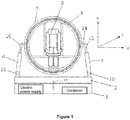
- FIG. 5 it is a schematic diagram of driving the bottom rotating base to rotate in the X-Y plane when the bottom rotating motor operates.
- the outer ring is disposed above the bottom rotating base, and n hydraulic rods are distributed between the outer ring and the bottom rotating base, n is a natural number; the bottom end of each hydraulic rod is hinged to the bottom rotating base, and the top of each hydraulic rod Hinged to the outer ring; each hydraulic rod is connected with a hydraulic pump; each hydraulic pump drives each hydraulic rod to perform a telescopic movement, thereby controlling the tilt angle of the outer ring in the X direction and/or the horizontal movement in the Y direction.
- each hydraulic rod is hinged to the bottom rotating base through the bottom cardan shaft; the top end of each hydraulic rod is hinged to the outer ring through the top cardan shaft.
- the diameter of the hydraulic rod is 100mm, the telescopic range is 700mm to 1300mm, and the number of hydraulic rods is preferably four, including: left front hydraulic rod, right front hydraulic rod, left rear hydraulic rod and right rear hydraulic rod. Therefore, the number of bottom cardan shafts is four, located at the four corners of the bottom rotating base, and the direction is upward for connecting the hydraulic rods.
- the number of top cardan shafts is four, which is used to connect the outer ring and the hydraulic rod and can be tilted by 15°.
- the outer ring can be a circular tube having a diameter of 1700 mm, a thickness of 50 mm, and a width of 200 mm.
- the outer ring is connected with an outer ring driving motor for driving the outer ring to rotate in the Y-Z plane; as shown in FIG. 4 , it is a schematic diagram of driving the outer ring to rotate in the Y-Z plane when the outer ring driving motor operates.
- the outer ring is also equipped with an outer ring locking mechanism, and the outer ring locking mechanism is used to limit the outer ring rotation.
- the inner ring can be rotatably sleeved inside the outer ring, and the inner ring can adopt a circular tube with a diameter of 1500 mm, a thickness of 50 mm and a width of 200 mm.
- the inner ring is connected with an inner ring driving motor for driving the inner ring to rotate in the X-Z plane; as shown in FIG. 6 , when the inner ring driving motor operates, the seat is rotated in the X-Z plane.
- An inner ring locking mechanism is also installed between the outer ring and the inner ring; the inner ring locking mechanism is used to fix the inner ring and the outer ring integrally, and the inner ring is prohibited from rotating relative to the outer ring.
- the seat is fixedly mounted inside the inner ring; the seat is provided with an operation panel and a pedal, and the seat can be extended into an upright mode; the seat is fixed to the inside of the inner ring by a 7-point fixing; the operation panel is extended by a telescopic extension rod It is fixed to the seat; when the operation panel is not needed, the extension rod is shortened so that the operation panel is in close contact with the seat surface of the seat, and the operator is not adversely affected when the operation panel is not required.
- the operation panel can be implemented by using a tablet with a touch function.
- the seat is also equipped with a leg sensor and a hand sensor; the leg sensor includes a sole displacement sensor, a two-legged outer sensor and a two-legged inner sensor for sensing the displacement of the leg in different directions, and the leg sensor can be fed back via a wireless Bluetooth signal. Operation panel. Through the legs, commands such as forward, backward, turn, dodge, squat, jump, and squat can be triggered.
- the seat reserves the hand sensor interface to achieve complex hand movement capture.
- the control panel is installed to synchronize operations and simulate driving, shooting, and hitting commands through the hand.
- Both the leg sensor and the hand sensor are connected to the input of the operation panel; the output of the operation panel is connected to the controller.
- the controller is respectively connected to the bottom rotating electric machine, the hydraulic pump, the outer ring driving motor and the inner ring driving motor; wherein the X axis and the Y axis form a horizontal plane, and the Z axis is an axis perpendicular to the horizontal plane.
- the invention also provides a simulation method for applying the above-mentioned multi-function VR human-computer interaction and external environment simulator, comprising the following steps:
- the controller controls the bottom rotating motor, the hydraulic pump, the outer ring driving motor and/or the inner ring driving motor, and specifically includes:
- the controller can be any of the bottom rotating electric machine, the hydraulic pump, the outer ring driving motor and the inner ring driving motor at the same time.
- One, any two, any three or any four simultaneous control thus achieving different combinations of displacement and rotation, simulating various application scenarios, such as playground, flight, car driving, shooting, fighting, surfing, bungee jumping and so on.
- the multi-function VR human-computer interaction and external environment simulator and simulation method provided by the invention can be applied to various virtual reality technology scenarios, and several specific application scenarios are listed below:
- the invention can realize multi-directional 360-degree rotation and multi-directional movement, when designing a virtual game, various playground equipment and simulation scenes can be freely designed, and the SDK interface (software development tool package) is developed through software. Kit) achieves simultaneous multi-directional rotation and movement, giving participants the most realistic simulation results.
- SDK interface software development tool package
- various racing virtual environments are designed.
- the steering wheel is used to simulate the steering wheel
- the foot contact is used to simulate the pedaling, braking, and the like.
- transmitted to the operation panel the operation panel on the one hand controls the player in the virtual scene.
- the simulator simulates the effects of forward tilting, sideways, bumps, etc., to bring real experience to the player.
- the present invention supports distributed virtual reality technology to realize networked multiplayer racing competition.
- the special driving simulation device According to the multi-directional flight, multi-angle sideways and rotation characteristics, various flight driving and air combat scenarios are designed through virtual reality technology, and the synchronization effect can be realized through the SDK interface, and the participants can be made. Free driving and achieving group combat effectiveness. Note that due to the high design difficulty of free-driving air combat games, such SDK interface logic will be designed by professional aircraft experts. Further, according to the outer ring device of the present invention, the player's limb simulation is horizontal, and the limbs such as the left and right sideways and the steering are simultaneously synchronized to simulate a gliding game.
- the player can carry forward, retreat, turn, squat, squat and even roll in the game, and cooperate with the simulation electron gun and motion capture system to realize the player's free steering and shooting action.
- the player's physical form allows the player to operate the game perfectly without extensive displacement and large volume movements.
- the player analyzes the body trajectory analysis and the limb shape analysis system in advance, and sets some fighting actions for the player. Through the triggering command, the player's movements in the game are controlled, and the external simulator is used to complete the reality.
- the device simulator After the player enters the game, the device simulator automatically rotates 180 degrees to simulate the player's sideways forward shape, and the rest of the control is the same as above.
- Virtual reality technology has just entered the stage of rapid development. With the continuous advancement of technology, the application scenarios in various real-world environments will gradually be realized in the virtual environment. We will gradually improve through continuous technological innovation, improvement and upgrade. The invention will also continuously develop a more convenient and realistic human-machine interactive simulation system.
Abstract
Description
- The disclosure belongs to the field of virtual reality "VR" technology, and particularly relates to a multi-function VR human-computer interaction and external environment simulator and simulation method.
- Virtual reality "VR" technology originated in the 1960s. It refers to the creation of a three-dimensional environment by means of computer systems and sensor technology, creating a new way of human-computer interaction by mobilizing users' various senses: visual, auditory, tactile, smell, etc. to enjoy a more realistic, immersive experience. With the improvement of hardware performance and the significant reduction of cost, in recent years, virtual reality products have been widely developed.
- In just two or three years, VR has become one of the most popular words in the technology circle. Virtual reality is a technology-intensive industry that can divide the virtual reality technology system into four aspects: perception, modeling, presentation and interaction. 2016 is called the first year of virtual reality "VR". In this year, the virtual reality industry policy is prosperous. In 2016, the public will understand that what is virtual reality will be an important year. The "Opinions of the Ministry of Culture on Promoting the Transformation and Upgrading of the Cultural and Entertainment Industry" issued by the Ministry of Culture is not the first national policy and regulation to promote the VR industry. Throughout 2016, as early as the two sessions, the "13th Five-Year Plan" outlined the VR industry as a six-field area of emerging frontier innovation. Subsequently, in April, the Electronic Technology Standardization Institute of the Ministry of Industry and Information Technology issued the "Virtual Reality Industry Development White Paper 5.0", calling on the state to start virtual reality research as soon as possible, establish a standard system, and regulate the development of the industry. The release of "Virtual Reality Industry Development White Paper 5.0" reflects the state's emphasis on virtual reality technology, and also indicates that the industry's unified standards construction process is accelerating, which will help improve virtual reality technology and promote the rapid development of industry norms.
- With its "human-computer interaction" and near-realistic "immersion", virtual reality technology quickly detonated the market and even appeared the "VR/AR+" boom. However, "virtual reality +" is far from imagining.
- At present, VR technology has been applied in many fields in China, and it has relatively mature applications in the viewing, real estate virtual environment display, tourism and game entertainment industries. In the current virtual reality field, a virtual environment is created by a computer. The virtual environment is a three-dimensional space formed by computer graphics. However, the participants are "invested" into the virtual environment through various sensing devices. In the implementation, the participants interact directly with the virtual environment, so that the participants visually create a feeling of being immersed in the virtual environment. However, in the virtual environment, the participants are almost isolated from the real environment. On the one hand, they pose certain security risks to the participants; on the other hand, the participants have limited experience.
- In view of the defects existing in the prior art, the present invention provides a multi-function VR human-computer interaction and external environment simulator and simulation method, which can effectively solve the above problems.
- The technical solution adopted by the present invention is as follows:
The invention provides a multifunctional VR human-computer interaction and external environment simulator, comprising: a base, a bottom rotating base, an outer ring, an inner ring, a seat and a controller, wherein: - the base is fixed on a horizontal floor;
- the bottom rotating base is rotatably mounted on the base, the rotating shaft of the bottom rotating base is connected with a bottom rotating electric machine, and the bottom rotating electric machine is used for driving the bottom rotating base to rotate in the X-Y plane;
- the outer ring is disposed above the bottom rotating base, and n hydraulic rods are distributed between the outer ring and the bottom rotating base, n is a natural number; the bottom end of each of the hydraulic rods is hinged to the rotating base and the top end of each of the hydraulic rods is hinged to the outer ring; each of the hydraulic rods is connected with a hydraulic pump; and each of the hydraulic rods is driven to perform a telescopic movement by each of the hydraulic pumps, further controlling the tilt angle of the outer ring in the X direction and/or the horizontal movement in the Y direction; further, the outer ring is connected with an outer ring drive motor for driving the outer ring to rotate in the YZ plane;
- the inner ring is rotatably sleeved inside the outer ring, and the inner ring is connected with an inner ring driving motor for driving the inner ring to rotate in the X-Z plane;
- the seat is fixedly mounted inside the inner ring; and
- the controller is respectively connected to the bottom rotating electrical machine, the hydraulic pump, the outer ring driving motor and the inner ring driving motor; wherein the X axis and the Y axis form a horizontal plane, and the Z axis is an axis perpendicular to a horizontal plane.
- Preferably, the base is fixed to the horizontal ground by an expansion bolt; an inner ring locking mechanism is further installed between the outer ring and the inner ring; and the inner ring locking mechanism is used to make the inner ring and the outer ring is fixedly formed integrally, and the inner ring is prohibited from rotating relative to the outer ring; the outer ring is further mounted with an outer ring locking mechanism for limiting rotation of the outer ring.
- Preferably, the bottom end of each of the hydraulic rods is hinged to the bottom rotating base by a bottom cardan shaft; the top end of each of the hydraulic rods is hinged to the outer ring by a top cardan shaft.
- Preferably, the hydraulic rods are arranged in a number of four, including: a left front hydraulic rod, a right front hydraulic rod, a left rear hydraulic rod, and a right rear hydraulic rod.
- Preferably, the seat is provided with an operation panel and a pedal, the seat can be extended into an upright mode; the seat is fixed to the inside of the inner ring by a 7-point fixing manner; the operation panel is retractable The extension rod is fixed to the seat; when the operation panel is not required, the extension rod is shortened so that the operation panel abuts against the seat surface of the seat.
- Preferably, the seat is further equipped with a leg sensor and a hand sensor; the leg sensor and the hand sensor are both connected to an input end of the operation panel; the output end of the operation panel is Controller connection.
- Preferably, the leg sensor comprises a sole displacement sensor, a two-legged outer sensor and a two-legged inner sensor.
- The invention also provides a simulation method for applying the above-mentioned multi-function VR human-computer interaction and external environment simulator, comprising the following steps:
- Step 1. The operation panel collects the participant's leg posture information and the hand posture information in real time through the leg sensor and the hand sensor;
- Step 2: The operation panel acquires a corresponding virtual manipulation instruction according to the pre-stored leg posture information, the correspondence between the hand posture information and the virtual manipulation instruction, or the operation panel directly receives the virtual manipulation of the virtual environment input by the participant. instruction;
- Step 3: The operation panel controls the virtual environment according to the virtual manipulation instruction obtained in step 2; on the other hand, controls the real environment, that is, the bottom rotating motor, the hydraulic pump, the outer ring driving motor, and / or the inner ring drive motor controls to control the attitude of the seat, ultimately achieving control of the participant's own posture.
- Preferably, in step 3, the controller controls the bottom rotating motor, the hydraulic pump, the outer ring driving motor and/or the inner ring driving motor, and specifically includes:
- The controller controls the action of the bottom rotating motor, and the bottom rotating motor drives the bottom rotating base to rotate in the X-Y plane, thereby driving the seat to rotate in the X-Y plane;
and/or - The controller controls the hydraulic pump action; wherein the hydraulic pump comprises: a left front hydraulic lever, a right front hydraulic lever, a left rear hydraulic lever and a right rear hydraulic lever; 1) when the controller controls the left front hydraulic lever, the right front hydraulic lever, When the left rear hydraulic rod and the right rear hydraulic rod are simultaneously extended in equal length, the outer ring is driven to rise, which in turn drives the seat to rise along the Z axis; 2) when the controller controls the left front hydraulic rod, the right front hydraulic rod, and the left When the rear hydraulic rod and the right rear hydraulic rod are shortened by the same length, the outer ring is driven to descend, thereby driving the seat to descend along the Z axis; 3) when the controller controls the left front hydraulic rod and the right front hydraulic rod to synchronize the elongation Set the length. At the same time, when the left rear hydraulic rod and the right rear hydraulic rod are controlled to shorten the preset length synchronously, the outer ring of the drive is horizontally moved forward along the Y axis, thereby driving the seat to move horizontally along the Y axis; 4) The controller controls the left front hydraulic rod and the right front hydraulic rod to synchronously shorten the preset length. At the same time, when the left rear hydraulic rod and the right rear hydraulic rod are controlled to synchronously extend the preset length, the outer ring is driven to move horizontally along the Y axis, thereby driving seat Horizontally moving rearward along the Y-axis; 5) when the controller controls the left front hydraulic lever and the left rear hydraulic lever to simultaneously shorten the preset length, and simultaneously controls the right front hydraulic lever and the right rear hydraulic lever to synchronously extend the preset length, The driving outer ring is inclined to the left by a preset angle, thereby driving the seat to be tilted to the left by a predetermined angle; 6) when the controller controls the left front hydraulic rod and the left rear hydraulic rod to simultaneously extend the preset length, and at the same time, controlling the right front hydraulic pressure When the rod and the right rear hydraulic rod are synchronized to shorten the preset length, the driving outer ring is tilted to the right by a predetermined angle, thereby driving the seat to the right to a predetermined angle;
and/or - The controller controls the action of the outer ring drive motor, and the outer ring drive motor drives the outer ring to rotate in the Y-Z plane, thereby driving the seat to rotate in the Y-Z plane;
and/or - The controller controls the inner ring to drive the motor to move, and the inner ring drive motor drives the inner ring to rotate in the X-Z plane, thereby driving the seat to rotate in the X-Z plane.
- The multi-function VR human-computer interaction and external environment simulator and simulation method provided by the invention have the following advantages:
The invention provides a multi-function VR human-computer interaction and external environment simulator and simulation method, which can realize the maximum self-control of the participants, and obtain the best self-perception in the real environment through the motion trajectory of the simulator. It has strong practicability and security, and also significantly enhances the real experience of participants. -
-
FIG. 1 is a front view of a multifunction VR human-computer interaction and external environment simulator provided by the present invention; -
FIG. 2 is a top view of a multi-function VR human-computer interaction and external environment simulator provided by the present invention; -
FIG. 3 is a side view of a multi-function VR human-computer interaction and external environment simulator provided by the present invention; -
FIG. 4 is a schematic diagram of the operation of the multi-function VR human-computer interaction and external environment simulator provided by the first driving function according to the present invention; -
FIG. 5 is a schematic diagram of the operation of the multi-function VR human-computer interaction and external environment simulator provided by the second driving action according to the present invention; -
FIG. 6 is a schematic diagram of the operation of the multi-function VR human-computer interaction and external environment simulator provided by the third driving action according to the present invention; -
FIG. 7 is a schematic diagram of the operation of the multi-function VR human-computer interaction and external environment simulator provided by the fourth driving action according to the present invention; -
FIG. 8 is a schematic diagram of the operation of the multi-function VR human-computer interaction and external environment simulator provided by the fifth driving function according to the present invention; -
FIG. 9 is a schematic diagram of the operation of the multi-function VR human-computer interaction and external environment simulator provided by the sixth driving function according to the present invention; - Where: 1 - base; 2 - bottom rotating base; 3 - outer ring; 4 - inner ring; 5 - seat; 6 - left front hydraulic bar; 7 - right front hydraulic bar; 8 - left rear hydraulic bar; 9 - right rear hydraulic bar;10 - universal joint shaft; 11 - operation panel; 12 - extension rod; 13 - bottom rotating motor; 14 - outer ring drive motor.
- The present invention will be further described in detail below with reference to the accompanying drawings and embodiments. It is understood that the specific embodiments described herein are merely illustrative of the invention and are not intended to limit the invention.
- For the VR experiencer in the virtual environment, completely isolated from the real environment, the participants cannot perfectly control their own technical problems. The present invention provides a multi-function VR human-computer interaction and external environment simulator and simulation method, with corresponding virtual environmental resources can realize the maximum control of the participants themselves, and obtain the best self-perception in the real environment through the trajectory of the simulator. It has strong practicability and security, and also significantly improves the participants' real experience.
- Referring to
Figures 1-3 , respectively, the main view, top view and side view of the multi-function VR human-computer interaction and external environment simulator, the multi-function VR human-computer interaction and external environment simulator includes: base, bottom rotating base, outer ring, inner ring, seat and controller. The following is a detailed description of each component: - The base is fixed to a level ground; for example, the base is fixed to a level ground by expansion bolts. The base is 2400*400mm in diameter and has a metal structure. A power supply module and controller are installed inside the base.
- The bottom rotating base is rotatably mounted on the upper surface of the base, the rotating shaft of the bottom rotating base is connected with a bottom rotating motor, the bottom rotating motor is used for driving the bottom rotating base to rotate in the X-Y plane; the bottom rotating base has a diameter of 2400*200 mm, and the metal structure. As shown in
FIG. 5 , it is a schematic diagram of driving the bottom rotating base to rotate in the X-Y plane when the bottom rotating motor operates. - The outer ring is disposed above the bottom rotating base, and n hydraulic rods are distributed between the outer ring and the bottom rotating base, n is a natural number; the bottom end of each hydraulic rod is hinged to the bottom rotating base, and the top of each hydraulic rod Hinged to the outer ring; each hydraulic rod is connected with a hydraulic pump; each hydraulic pump drives each hydraulic rod to perform a telescopic movement, thereby controlling the tilt angle of the outer ring in the X direction and/or the horizontal movement in the Y direction.
- In practical applications, the bottom end of each hydraulic rod is hinged to the bottom rotating base through the bottom cardan shaft; the top end of each hydraulic rod is hinged to the outer ring through the top cardan shaft. The diameter of the hydraulic rod is 100mm, the telescopic range is 700mm to 1300mm, and the number of hydraulic rods is preferably four, including: left front hydraulic rod, right front hydraulic rod, left rear hydraulic rod and right rear hydraulic rod. Therefore, the number of bottom cardan shafts is four, located at the four corners of the bottom rotating base, and the direction is upward for connecting the hydraulic rods. The number of top cardan shafts is four, which is used to connect the outer ring and the hydraulic rod and can be tilted by 15°.
- The outer ring can be a circular tube having a diameter of 1700 mm, a thickness of 50 mm, and a width of 200 mm.
- In addition, the outer ring is connected with an outer ring driving motor for driving the outer ring to rotate in the Y-Z plane; as shown in
FIG. 4 , it is a schematic diagram of driving the outer ring to rotate in the Y-Z plane when the outer ring driving motor operates. The outer ring is also equipped with an outer ring locking mechanism, and the outer ring locking mechanism is used to limit the outer ring rotation. - The inner ring can be rotatably sleeved inside the outer ring, and the inner ring can adopt a circular tube with a diameter of 1500 mm, a thickness of 50 mm and a width of 200 mm. The inner ring is connected with an inner ring driving motor for driving the inner ring to rotate in the X-Z plane; as shown in
FIG. 6 , when the inner ring driving motor operates, the seat is rotated in the X-Z plane. An inner ring locking mechanism is also installed between the outer ring and the inner ring; the inner ring locking mechanism is used to fix the inner ring and the outer ring integrally, and the inner ring is prohibited from rotating relative to the outer ring. - The seat is fixedly mounted inside the inner ring; the seat is provided with an operation panel and a pedal, and the seat can be extended into an upright mode; the seat is fixed to the inside of the inner ring by a 7-point fixing; the operation panel is extended by a telescopic extension rod It is fixed to the seat; when the operation panel is not needed, the extension rod is shortened so that the operation panel is in close contact with the seat surface of the seat, and the operator is not adversely affected when the operation panel is not required. The operation panel can be implemented by using a tablet with a touch function.
- The seat is also equipped with a leg sensor and a hand sensor; the leg sensor includes a sole displacement sensor, a two-legged outer sensor and a two-legged inner sensor for sensing the displacement of the leg in different directions, and the leg sensor can be fed back via a wireless Bluetooth signal. Operation panel. Through the legs, commands such as forward, backward, turn, dodge, squat, jump, and squat can be triggered.
- Hand sensor: The seat reserves the hand sensor interface to achieve complex hand movement capture. The control panel is installed to synchronize operations and simulate driving, shooting, and hitting commands through the hand.
- Both the leg sensor and the hand sensor are connected to the input of the operation panel; the output of the operation panel is connected to the controller.
- The controller is respectively connected to the bottom rotating electric machine, the hydraulic pump, the outer ring driving motor and the inner ring driving motor; wherein the X axis and the Y axis form a horizontal plane, and the Z axis is an axis perpendicular to the horizontal plane.
- The invention also provides a simulation method for applying the above-mentioned multi-function VR human-computer interaction and external environment simulator, comprising the following steps:
- Step 1. The operation panel collects the participant's leg posture information and the hand posture information in real time through the leg sensor and the hand sensor;
- Step 2: The operation panel acquires a corresponding virtual manipulation instruction according to the pre-stored leg posture information, the correspondence between the hand posture information and the virtual manipulation instruction, or the operation panel directly receives the virtual manipulation of the virtual environment input by the participant. instruction;
- Step 3: The operation panel controls the virtual environment according to the virtual manipulation instruction obtained in step 2; on the other hand, controls the real environment, that is, the bottom rotating motor, the hydraulic pump, the outer ring drive motor, and/or The inner ring drive motor controls to control the attitude of the seat, ultimately achieving control of the participant's own posture.
- In this step, the controller controls the bottom rotating motor, the hydraulic pump, the outer ring driving motor and/or the inner ring driving motor, and specifically includes:
- The controller controls the action of the bottom rotating motor, and the bottom rotating motor drives the bottom rotating base to rotate in the X-Y plane, thereby driving the seat to rotate in the X-Y plane;
and/or - The controller controls the hydraulic pump action; wherein the hydraulic pump comprises: a left front hydraulic lever, a right front hydraulic lever, a left rear hydraulic lever and a right rear hydraulic lever; 1) when the controller controls the left front hydraulic lever, the right front hydraulic lever, and the left rear hydraulic lever When the right rear hydraulic rod is synchronized with the same length, the outer ring is driven to rise, which in turn drives the seat to rise along the Z axis; 2) when the controller controls the left front hydraulic lever, the right front hydraulic lever, the left rear hydraulic lever, and the right rear When the synchronous length of the hydraulic rod is shortened, the outer ring is driven to perform the lowering action, thereby driving the seat to descend along the Z axis; referring to
FIG. 8 , a schematic diagram of driving the seat along the Z axis; 3) when the controller controls the left front hydraulic rod Synchronously extending the preset length with the right front hydraulic rod, and simultaneously controlling the left rear hydraulic rod and the right rear hydraulic rod to shorten the preset length, the driving outer ring moves horizontally along the Y-axis front, thereby driving the seat along the Y-axis front. Move horizontally; 4) When the controller controls the left front hydraulic rod and the right front hydraulic rod to shorten the preset length synchronously, and simultaneously controls the left rear hydraulic rod and the right rear hydraulic rod to synchronously extend the preset length, the outer ring is driven to move horizontally along the Y axis, which in turn drives the seat to move horizontally along the Y-axis; referring toFIG. 7 , a schematic diagram of driving the seat to move horizontally forward and backward along the Y-axis; 5) when the controller controls the left front hydraulic lever and the left rear hydraulic lever to shorten the preset Length, at the same time, when controlling the right front hydraulic rod and the right rear hydraulic rod to synchronously extend the preset length, the driving outer ring is tilted to the left by a predetermined angle, thereby driving the seat to the left to tilt the preset angle; 6) when the controller controls the left front The hydraulic rod and the left rear hydraulic rod are synchronously extended by a preset length. At the same time, when the right front hydraulic rod and the right rear hydraulic rod are controlled to shorten the preset length, the outer ring is driven to the right by a predetermined angle, thereby driving the seat to the right. Set the angle; refer toFIG. 9 , which is a schematic diagram of driving the seat to tilt left and right;
and/or - The controller controls the action of the outer ring drive motor, and the outer ring drive motor drives the outer ring to rotate in the YZ plane, thereby driving the seat to rotate in the YZ plane; as shown in
FIG. 4 , when the outer ring drive motor operates, it drives the outer ring Schematic diagram of the rotation of the ring in the YZ plane.
and/or - The controller controls the inner ring to drive the motor to move, and the inner ring drive motor drives the inner ring to rotate in the X-Z plane, thereby driving the seat to rotate in the X-Z plane. As shown in
FIG. 6 , when the inner ring drive motor operates, the seat is rotated in the X-Z plane. - It should be emphasized that, for the multi-function VR human-computer interaction and external environment simulator provided by the present invention, the controller can be any of the bottom rotating electric machine, the hydraulic pump, the outer ring driving motor and the inner ring driving motor at the same time. One, any two, any three or any four simultaneous control, thus achieving different combinations of displacement and rotation, simulating various application scenarios, such as playground, flight, car driving, shooting, fighting, surfing, bungee jumping and so on.
- The multi-function VR human-computer interaction and external environment simulator and simulation method provided by the invention can be applied to various virtual reality technology scenarios, and several specific application scenarios are listed below:
- Since the invention can realize multi-directional 360-degree rotation and multi-directional movement, when designing a virtual game, various playground equipment and simulation scenes can be freely designed, and the SDK interface (software development tool package) is developed through software. Kit) achieves simultaneous multi-directional rotation and movement, giving participants the most realistic simulation results.
- In conjunction with the dedicated driving simulation device, combined with the motion trajectory of the present invention, various racing virtual environments are designed. For example, when the player is in the game scene, the steering wheel is used to simulate the steering wheel, and the foot contact is used to simulate the pedaling, braking, and the like. , transmitted to the operation panel, the operation panel on the one hand controls the player in the virtual scene. On the other hand, through the SDK interface, the simulator simulates the effects of forward tilting, sideways, bumps, etc., to bring real experience to the player. Moreover, the present invention supports distributed virtual reality technology to realize networked multiplayer racing competition.
- With the special driving simulation device, according to the multi-directional flight, multi-angle sideways and rotation characteristics, various flight driving and air combat scenarios are designed through virtual reality technology, and the synchronization effect can be realized through the SDK interface, and the participants can be made. Free driving and achieving group combat effectiveness. Note that due to the high design difficulty of free-driving air combat games, such SDK interface logic will be designed by professional aircraft experts. Further, according to the outer ring device of the present invention, the player's limb simulation is horizontal, and the limbs such as the left and right sideways and the steering are simultaneously synchronized to simulate a gliding game.
- Through the foot motion sensor, the player can carry forward, retreat, turn, squat, squat and even roll in the game, and cooperate with the simulation electron gun and motion capture system to realize the player's free steering and shooting action. The player's physical form allows the player to operate the game perfectly without extensive displacement and large volume movements.
- In the design of the fighting game, the player analyzes the body trajectory analysis and the limb shape analysis system in advance, and sets some fighting actions for the player. Through the triggering command, the player's movements in the game are controlled, and the external simulator is used to complete the reality. The limb shape, and through the function of the front and rear, side direction movement and inversion of the present invention, simulates the force and the reaction force to achieve a real fighting effect.
- After the player enters the game, the device simulator automatically rotates 180 degrees to simulate the player's sideways forward shape, and the rest of the control is the same as above.
- Virtual reality technology has just entered the stage of rapid development. With the continuous advancement of technology, the application scenarios in various real-world environments will gradually be realized in the virtual environment. We will gradually improve through continuous technological innovation, improvement and upgrade. The invention will also continuously develop a more convenient and realistic human-machine interactive simulation system.
- The above description is only a preferred embodiment of the present invention, and it should be noted that those skilled in the art can also make several improvements and variations without departing from the principles of the present invention. The scope of protection of the invention should be considered.
Claims (9)
- A multi-functional VR human-computer interaction and external environment simulator, comprising: a base (1), a bottom rotating base (2), an outer ring (3), an inner ring (4), a seat (5), and a controller, wherein- the base is fixed on a horizontal floor;- the bottom rotating base is rotatably mounted on the base, a rotating shaft of the bottom rotating base being connected to a bottom rotating electric machine, and the bottom rotating electric machine is used for driving the bottom rotating base to rotate in an X-Y plane;- the outer ring is disposed above the bottom rotating base and n hydraulic rods are distributed between the outer ring and the bottom rotating base, n being a natural number, a bottom end of each of the hydraulic rods being hinged to the bottom rotating base and a top end of each of the hydraulic rods being hinged to the outer ring, each of the hydraulic rods being connected with a hydraulic pump, each of the hydraulic rods being driven to perform a telescopic movement by each of the hydraulic pumps for controlling a tilt angle of the outer ring in an X direction and/or a horizontal movement in a Y direction, and the outer ring is connected with an outer ring drive motor for driving the outer ring to rotate in an Y-Z plane;- the inner ring is rotatably sleeved inside the outer ring, and the inner ring is connected to an inner ring driving motor for driving the inner ring to rotate in an X-Z plane;- the seat is fixedly mounted inside the inner ring; and- the controller is respectively connected to the bottom rotating electrical machine, the hydraulic pumps, an outer ring driving motor and the inner ring driving motor;wherein an X axis and a Y axis form a horizontal plane, and a Z axis is an axis perpendicular to a horizontal plane.
- The multi-function VR human-computer interaction and external environment simulator according to claim 1, wherein:- the base is fixed to the horizontal floor by an expansion bolt;- an inner ring locking mechanism is installed between the outer ring and the inner ring, the inner ring locking mechanism being configured to fix the inner ring and the outer ring integrally to each other and to prohibit the inner ring from rotating relative to the outer ring; and- there is an outer ring locking mechanism for limiting the rotation of the outer ring.
- The multi-function VR human-computer interaction and external environment simulator according to claim 1, wherein the bottom end of each of the hydraulic rods is hinged to the bottom rotating base through a bottom cardan shaft and the top end of the hydraulic rod is hinged to the outer ring by a top cardan shaft.
- The multi-function VR human-computer interaction and external environment simulator according to claim 1, wherein the number of the hydraulic rods is four, including: a left front hydraulic rod (6), a right front hydraulic rod (7), and a left rear hydraulic rod (8), and a right rear hydraulic rod (9).
- The multi-function VR human-computer interaction and external environment simulator according to claim 1, wherein the seat is provided with an operation panel and a pedal, and the seat can be extended into an upright mode, the seat is fixed to the inside of the inner ring with a 7-point fixing manner, the operation panel is fixed to the seat by a telescopic extension rod suitable for being shortened when the operation panel is not required.
- The multi-function VR human-computer interaction and external environment simulator according to claim 5, wherein the seat is further equipped with a leg sensor and a hand sensor, and the leg sensor and the hand sensor are each connected to an input of the operation panel, an output of the operation panel being connected to the controller.
- The multi-function VR human-computer interaction and external environment simulator according to claim 6, wherein the leg sensor comprises a sole displacement sensor, a two-legged outer sensor, and a two-legged inner sensor.
- A simulation method for a multi-function VR human-computer interaction and external environment simulator according to any one of claims 1 to 7, characterized in that it comprises the following steps:Step 1: the operation panel collects a participant's leg posture information and hand posture information in real time through the leg sensor and the hand sensor;Step 2: the operation panel acquires a virtual manipulation instruction according to the leg posture information and hand posture information, or the operation panel directly receives the virtual manipulation instruction by participant instruction; andStep 3: the controller controls the virtual environment according to the virtual manipulation instruction obtained in step 2 by controlling a real environment being a bottom rotating motor, the hydraulic pumps, the outer ring driving motor, and/or the inner ring drive motor to control an attitude of the seat for achieving control of the participant's own posture.
- The simulation method according to claim 8, wherein the controller controls, in the step 3, the bottom rotating motor, the hydraulic pumps, the outer ring drive motor, and/or the inner ring drive motor so that:- the controller controls an action of the bottom rotating motor, and the bottom rotating motor drives the bottom rotating base to rotate in the X-Y plane, thereby driving the bottom rotating base to rotate in the X-Y plane;
and/or- the controller controls the hydraulic pumps to control the left front hydraulic rod, the right front hydraulic rod, the left rear hydraulic rod, and the right rear hydraulic rod so that: 1) when the left front hydraulic rod, the right front hydraulic rod, the left rear hydraulic rod, and the right rear hydraulic rod are simultaneously extended by a same length, the outer ring is driven to rise thereby driving the seat to rise along the Z axis, 2) when the left front hydraulic rod, the right front hydraulic rod, the left rear hydraulic rod, and the right rear hydraulic rod are shortened by a same length, the outer ring is driven to descend thereby driving the seat to descend along the Z axis, 3) when the left front hydraulic rod and the right front hydraulic rod are extended by a same length and simultaneously the left rear hydraulic rod and the right rear hydraulic rod are shortened by a same length, the outer ring of the drive is horizontally moved forward along the Y axis thereby driving the seat to move horizontally forward along the Y axis, 4) when the left front hydraulic rod and the right front hydraulic rod are shortened by a same length and simultaneously the left rear hydraulic rod and the right rear hydraulic rod are extended by a same length, the outer ring is horizontally moved rearward along the Y axis thereby driving the seat to move horizontally rearward along the Y axis, 5) when the left front hydraulic lever and the left rear hydraulic lever to are shortened by a same length and simultaneously the right front hydraulic lever and the right rear hydraulic lever are extended by a same length, the outer ring is inclined to left by a preset angle thereby driving the seat to be tilted to the left by the preset angle, and 6) when the left front hydraulic lever and the left rear hydraulic lever to are extended by a same length and simultaneously the right front hydraulic lever and the right rear hydraulic lever are shortened by a same length, the outer ring is inclined to right by a preset angle thereby driving the seat to be tilted to the right by the preset angle;
and/or- the controller controls an action of the outer ring driving motor, and the outer ring driving motor drives the outer ring to rotate in the Y-Z plane, thereby driving the seat to rotate in the Y-Z plane;
and/or- the controller controls the inner ring driving motor to move, and the inner ring driving motor drives the inner ring to rotate in the X-Z plane, thereby driving the seat to rotate in the X-Z plane.
Applications Claiming Priority (2)
| Application Number | Priority Date | Filing Date | Title |
|---|---|---|---|
| CN201610946941.3A CN106297473B (en) | 2016-10-26 | 2016-10-26 | Using multi-functional VR man-machine interactions and the analogy method of the simulator of external environment condition |
| PCT/CN2017/107430 WO2018077155A1 (en) | 2016-10-26 | 2017-10-24 | Multifunctional vr human-computer interaction and external environment simulator and simulation method |
Publications (3)
| Publication Number | Publication Date |
|---|---|
| EP3534355A1 true EP3534355A1 (en) | 2019-09-04 |
| EP3534355A4 EP3534355A4 (en) | 2020-03-04 |
| EP3534355B1 EP3534355B1 (en) | 2021-03-24 |
Family
ID=57720344
Family Applications (1)
| Application Number | Title | Priority Date | Filing Date |
|---|---|---|---|
| EP17864448.0A Active EP3534355B1 (en) | 2016-10-26 | 2017-10-24 | Multifunctional vr human-computer interaction and external environment simulator and simulation method |
Country Status (4)
| Country | Link |
|---|---|
| EP (1) | EP3534355B1 (en) |
| CN (1) | CN106297473B (en) |
| ES (1) | ES2872968T3 (en) |
| WO (1) | WO2018077155A1 (en) |
Cited By (1)
| Publication number | Priority date | Publication date | Assignee | Title |
|---|---|---|---|---|
| CN112598960A (en) * | 2020-12-03 | 2021-04-02 | 南京全控航空科技有限公司 | Multi-degree-of-freedom motion platform for flight simulator and operation method |
Families Citing this family (19)
| Publication number | Priority date | Publication date | Assignee | Title |
|---|---|---|---|---|
| CN106297473B (en) * | 2016-10-26 | 2017-08-29 | 覃伟 | Using multi-functional VR man-machine interactions and the analogy method of the simulator of external environment condition |
| CN106648116B (en) * | 2017-01-22 | 2023-06-20 | 隋文涛 | Virtual reality integrated system based on motion capture |
| CN107261495B (en) * | 2017-06-02 | 2020-10-09 | 歌尔科技有限公司 | Motion seat control method and device |
| CN107393351A (en) * | 2017-09-05 | 2017-11-24 | 国家电网公司 | A kind of trainer and Training Methodology of walking of the training on electric power based on VR systems |
| CN107694090A (en) * | 2017-09-29 | 2018-02-16 | 广州云友网络科技有限公司 | A kind of simulated flight system of virtual scene combination manipulator |
| CN109771938A (en) * | 2017-11-15 | 2019-05-21 | 成都有尔天弘科技有限公司 | Virtual reality auxiliary appliance system and control method |
| CN107919049A (en) * | 2017-12-24 | 2018-04-17 | 佛山市龙远科技有限公司 | A kind of simulation travelling experiencing system based on VR |
| CN108492667A (en) * | 2018-05-24 | 2018-09-04 | 山东科技大学 | A kind of multi-angle, multi-pose flight training simulator |
| CN109999487B (en) * | 2019-04-25 | 2023-02-03 | 苏州辽亚自动化有限公司 | VR virtual recreation is with multi-angle rotating's activity seat |
| CN110152289B (en) * | 2019-07-08 | 2022-08-16 | 青岛海科虚拟现实研究院 | Seat is felt to body based on VR simulation |
| IT202000015337A1 (en) * | 2020-06-25 | 2021-12-25 | Vvr S R L | SIMULATION DEVICE FOR VIRTUAL REALITY EXPERIENCES |
| CN111784848A (en) * | 2020-08-07 | 2020-10-16 | 任丽润 | Three-dimensional scene simulation device based on VR and AR |
| CN112150881A (en) * | 2020-10-12 | 2020-12-29 | 武汉艺术先生数码科技有限公司 | VR training simulation device |
| CN112489523A (en) * | 2020-12-21 | 2021-03-12 | 东南大学 | Space detection mobile manned virtual simulation system |
| CN113101642B (en) * | 2021-04-06 | 2023-11-28 | 长沙理工大学 | Virtual reality self-service game device |
| CN114360312A (en) * | 2021-12-17 | 2022-04-15 | 江西洪都航空工业集团有限责任公司 | Ground service maintenance training system and method based on augmented reality technology |
| CN114265507B (en) * | 2021-12-31 | 2024-03-12 | 泰古旅(上海)创意设计有限公司 | Panorama VR immersion type multi-angle tourist attraction propaganda system |
| CN114558280B (en) * | 2022-04-24 | 2022-08-02 | 之江实验室 | Multi-scene intelligent sports equipment based on double-leg posture prediction and use method thereof |
| CN115793874B (en) * | 2023-02-03 | 2023-05-05 | 广州奇境科技有限公司 | Virtual reality remote interaction equipment |
Family Cites Families (11)
| Publication number | Priority date | Publication date | Assignee | Title |
|---|---|---|---|---|
| GB131363A (en) * | 1918-05-17 | 1919-08-28 | ||
| US3135057A (en) * | 1960-04-28 | 1964-06-02 | Northrop Corp | Flight simulator |
| US4856771A (en) * | 1987-10-22 | 1989-08-15 | Nelson, Berg Enterprises | Video simulation apparatus |
| CN2165899Y (en) * | 1993-09-13 | 1994-05-25 | 郑州市曙光机器厂 | Two-dimension rotary computer games |
| US6533670B1 (en) * | 2000-08-14 | 2003-03-18 | Universal City Studio, Inc. | Amusement ride with pivotable motion base |
| DE102011102037B4 (en) * | 2011-05-16 | 2014-05-15 | Johannes Kreuz | Full rotation Simulator |
| CN203165265U (en) * | 2013-03-28 | 2013-08-28 | 周校平 | Universal type logistics equipment simulation training device |
| BR202015008770Y1 (en) * | 2015-04-17 | 2020-12-01 | Motion Sphere Desenvolvimento De Tecnologia E Locações Ltda - Epp | provisions applied in spherical simulator of virtual accelerations |
| CN105214307B (en) * | 2015-11-17 | 2019-01-15 | 广州卓远虚拟现实科技有限公司 | VR motion-sensing game machine |
| CN105955487B (en) * | 2016-05-24 | 2018-10-02 | 天津锡跃科技有限公司 | VR coordinative composition of equipments seats |
| CN106297473B (en) * | 2016-10-26 | 2017-08-29 | 覃伟 | Using multi-functional VR man-machine interactions and the analogy method of the simulator of external environment condition |
-
2016
- 2016-10-26 CN CN201610946941.3A patent/CN106297473B/en active Active
-
2017
- 2017-10-24 ES ES17864448T patent/ES2872968T3/en active Active
- 2017-10-24 EP EP17864448.0A patent/EP3534355B1/en active Active
- 2017-10-24 WO PCT/CN2017/107430 patent/WO2018077155A1/en unknown
Cited By (1)
| Publication number | Priority date | Publication date | Assignee | Title |
|---|---|---|---|---|
| CN112598960A (en) * | 2020-12-03 | 2021-04-02 | 南京全控航空科技有限公司 | Multi-degree-of-freedom motion platform for flight simulator and operation method |
Also Published As
| Publication number | Publication date |
|---|---|
| EP3534355A4 (en) | 2020-03-04 |
| EP3534355B1 (en) | 2021-03-24 |
| WO2018077155A1 (en) | 2018-05-03 |
| CN106297473B (en) | 2017-08-29 |
| CN106297473A (en) | 2017-01-04 |
| ES2872968T3 (en) | 2021-11-03 |
Similar Documents
| Publication | Publication Date | Title |
|---|---|---|
| EP3534355B1 (en) | Multifunctional vr human-computer interaction and external environment simulator and simulation method | |
| Cheng et al. | Haptic turk: a motion platform based on people | |
| US10124211B2 (en) | Device for carrying out movements by shifting the center of gravity and/or actuating muscles of a human body | |
| TWI831066B (en) | Method for state switching in virtual scene, device, apparatus, medium and program product | |
| CN202171880U (en) | A three-dimensional visual simulation driving system | |
| JPH0950539A (en) | Method and device for generating virtual picture | |
| CN107694093B (en) | Method, device, equipment and storage medium for controlling grabbing of prop model in game | |
| JPH08320949A (en) | Picture processor and game device using the processor | |
| CN206672418U (en) | A kind of rotary simulation system of Three Degree Of Freedom | |
| KR20170045679A (en) | First person shooter game device using head mounted display | |
| CN111462574A (en) | Flight training simulation system | |
| JPH08117440A (en) | Three-dimensional simulator device and image synthesis method | |
| US20110165943A1 (en) | Flight and Motion Simulator Control Mechanism | |
| KR102328405B1 (en) | 4d vr simulation system with increased flying feel | |
| CN211181201U (en) | Simulation flight science popularization experience equipment | |
| JP3642779B2 (en) | 3D simulator apparatus and image composition method | |
| JP5957258B2 (en) | Program, information storage medium, game device, and server system | |
| EP3438951B1 (en) | Haptic feedback device for steering simulation | |
| US20230277936A1 (en) | Information processing system, non-transitory computer-readable storage medium having stored therein information processing program, information processing method, and information processing apparatus | |
| TWI380843B (en) | Remote control toys and electronic game integrated interface | |
| JP2019193705A (en) | Game program and game device | |
| KR102624214B1 (en) | VR simulator and realistic contents system using thereof | |
| US20240119858A1 (en) | Systems of flight simulation and methods of operating same | |
| Rodriguez Baquero et al. | MechVR post-mortem-Navigating design challenges for a VR game | |
| CN205121732U (en) | All -round motion spring response mechanism |
Legal Events
| Date | Code | Title | Description |
|---|---|---|---|
| STAA | Information on the status of an ep patent application or granted ep patent |
Free format text: STATUS: THE INTERNATIONAL PUBLICATION HAS BEEN MADE |
|
| PUAI | Public reference made under article 153(3) epc to a published international application that has entered the european phase |
Free format text: ORIGINAL CODE: 0009012 |
|
| STAA | Information on the status of an ep patent application or granted ep patent |
Free format text: STATUS: REQUEST FOR EXAMINATION WAS MADE |
|
| 17P | Request for examination filed |
Effective date: 20190429 |
|
| AK | Designated contracting states |
Kind code of ref document: A1 Designated state(s): AL AT BE BG CH CY CZ DE DK EE ES FI FR GB GR HR HU IE IS IT LI LT LU LV MC MK MT NL NO PL PT RO RS SE SI SK SM TR |
|
| AX | Request for extension of the european patent |
Extension state: BA ME |
|
| DAV | Request for validation of the european patent (deleted) | ||
| DAX | Request for extension of the european patent (deleted) | ||
| A4 | Supplementary search report drawn up and despatched |
Effective date: 20200205 |
|
| RIC1 | Information provided on ipc code assigned before grant |
Ipc: G09B 9/14 20060101ALI20200130BHEP Ipc: A63F 13/21 20140101ALI20200130BHEP Ipc: G09B 9/12 20060101ALI20200130BHEP Ipc: G09B 9/00 20060101AFI20200130BHEP |
|
| GRAP | Despatch of communication of intention to grant a patent |
Free format text: ORIGINAL CODE: EPIDOSNIGR1 |
|
| STAA | Information on the status of an ep patent application or granted ep patent |
Free format text: STATUS: GRANT OF PATENT IS INTENDED |
|
| INTG | Intention to grant announced |
Effective date: 20201102 |
|
| GRAS | Grant fee paid |
Free format text: ORIGINAL CODE: EPIDOSNIGR3 |
|
| STAA | Information on the status of an ep patent application or granted ep patent |
Free format text: STATUS: GRANT OF PATENT IS INTENDED |
|
| GRAA | (expected) grant |
Free format text: ORIGINAL CODE: 0009210 |
|
| STAA | Information on the status of an ep patent application or granted ep patent |
Free format text: STATUS: THE PATENT HAS BEEN GRANTED |
|
| AK | Designated contracting states |
Kind code of ref document: B1 Designated state(s): AL AT BE BG CH CY CZ DE DK EE ES FI FR GB GR HR HU IE IS IT LI LT LU LV MC MK MT NL NO PL PT RO RS SE SI SK SM TR |
|
| REG | Reference to a national code |
Ref country code: GB Ref legal event code: FG4D |
|
| REG | Reference to a national code |
Ref country code: CH Ref legal event code: EP |
|
| REG | Reference to a national code |
Ref country code: IE Ref legal event code: FG4D |
|
| REG | Reference to a national code |
Ref country code: DE Ref legal event code: R096 Ref document number: 602017035447 Country of ref document: DE Ref country code: AT Ref legal event code: REF Ref document number: 1375285 Country of ref document: AT Kind code of ref document: T Effective date: 20210415 |
|
| REG | Reference to a national code |
Ref country code: SE Ref legal event code: TRGR |
|
| REG | Reference to a national code |
Ref country code: FI Ref legal event code: FGE |
|
| REG | Reference to a national code |
Ref country code: NL Ref legal event code: FP |
|
| REG | Reference to a national code |
Ref country code: EE Ref legal event code: FG4A Ref document number: E020912 Country of ref document: EE Effective date: 20210531 |
|
| REG | Reference to a national code |
Ref country code: LT Ref legal event code: MG9D |
|
| PG25 | Lapsed in a contracting state [announced via postgrant information from national office to epo] |
Ref country code: NO Free format text: LAPSE BECAUSE OF FAILURE TO SUBMIT A TRANSLATION OF THE DESCRIPTION OR TO PAY THE FEE WITHIN THE PRESCRIBED TIME-LIMIT Effective date: 20210624 Ref country code: HR Free format text: LAPSE BECAUSE OF FAILURE TO SUBMIT A TRANSLATION OF THE DESCRIPTION OR TO PAY THE FEE WITHIN THE PRESCRIBED TIME-LIMIT Effective date: 20210324 Ref country code: GR Free format text: LAPSE BECAUSE OF FAILURE TO SUBMIT A TRANSLATION OF THE DESCRIPTION OR TO PAY THE FEE WITHIN THE PRESCRIBED TIME-LIMIT Effective date: 20210625 Ref country code: BG Free format text: LAPSE BECAUSE OF FAILURE TO SUBMIT A TRANSLATION OF THE DESCRIPTION OR TO PAY THE FEE WITHIN THE PRESCRIBED TIME-LIMIT Effective date: 20210624 |
|
| PG25 | Lapsed in a contracting state [announced via postgrant information from national office to epo] |
Ref country code: RS Free format text: LAPSE BECAUSE OF FAILURE TO SUBMIT A TRANSLATION OF THE DESCRIPTION OR TO PAY THE FEE WITHIN THE PRESCRIBED TIME-LIMIT Effective date: 20210324 Ref country code: LV Free format text: LAPSE BECAUSE OF FAILURE TO SUBMIT A TRANSLATION OF THE DESCRIPTION OR TO PAY THE FEE WITHIN THE PRESCRIBED TIME-LIMIT Effective date: 20210324 |
|
| REG | Reference to a national code |
Ref country code: AT Ref legal event code: MK05 Ref document number: 1375285 Country of ref document: AT Kind code of ref document: T Effective date: 20210324 |
|
| PG25 | Lapsed in a contracting state [announced via postgrant information from national office to epo] |
Ref country code: SM Free format text: LAPSE BECAUSE OF FAILURE TO SUBMIT A TRANSLATION OF THE DESCRIPTION OR TO PAY THE FEE WITHIN THE PRESCRIBED TIME-LIMIT Effective date: 20210324 Ref country code: LT Free format text: LAPSE BECAUSE OF FAILURE TO SUBMIT A TRANSLATION OF THE DESCRIPTION OR TO PAY THE FEE WITHIN THE PRESCRIBED TIME-LIMIT Effective date: 20210324 Ref country code: CZ Free format text: LAPSE BECAUSE OF FAILURE TO SUBMIT A TRANSLATION OF THE DESCRIPTION OR TO PAY THE FEE WITHIN THE PRESCRIBED TIME-LIMIT Effective date: 20210324 Ref country code: AT Free format text: LAPSE BECAUSE OF FAILURE TO SUBMIT A TRANSLATION OF THE DESCRIPTION OR TO PAY THE FEE WITHIN THE PRESCRIBED TIME-LIMIT Effective date: 20210324 |
|
| REG | Reference to a national code |
Ref country code: ES Ref legal event code: FG2A Ref document number: 2872968 Country of ref document: ES Kind code of ref document: T3 Effective date: 20211103 |
|
| PG25 | Lapsed in a contracting state [announced via postgrant information from national office to epo] |
Ref country code: IS Free format text: LAPSE BECAUSE OF FAILURE TO SUBMIT A TRANSLATION OF THE DESCRIPTION OR TO PAY THE FEE WITHIN THE PRESCRIBED TIME-LIMIT Effective date: 20210724 Ref country code: PL Free format text: LAPSE BECAUSE OF FAILURE TO SUBMIT A TRANSLATION OF THE DESCRIPTION OR TO PAY THE FEE WITHIN THE PRESCRIBED TIME-LIMIT Effective date: 20210324 Ref country code: PT Free format text: LAPSE BECAUSE OF FAILURE TO SUBMIT A TRANSLATION OF THE DESCRIPTION OR TO PAY THE FEE WITHIN THE PRESCRIBED TIME-LIMIT Effective date: 20210726 Ref country code: SK Free format text: LAPSE BECAUSE OF FAILURE TO SUBMIT A TRANSLATION OF THE DESCRIPTION OR TO PAY THE FEE WITHIN THE PRESCRIBED TIME-LIMIT Effective date: 20210324 Ref country code: RO Free format text: LAPSE BECAUSE OF FAILURE TO SUBMIT A TRANSLATION OF THE DESCRIPTION OR TO PAY THE FEE WITHIN THE PRESCRIBED TIME-LIMIT Effective date: 20210324 |
|
| REG | Reference to a national code |
Ref country code: DE Ref legal event code: R097 Ref document number: 602017035447 Country of ref document: DE |
|
| PG25 | Lapsed in a contracting state [announced via postgrant information from national office to epo] |
Ref country code: AL Free format text: LAPSE BECAUSE OF FAILURE TO SUBMIT A TRANSLATION OF THE DESCRIPTION OR TO PAY THE FEE WITHIN THE PRESCRIBED TIME-LIMIT Effective date: 20210324 Ref country code: DK Free format text: LAPSE BECAUSE OF FAILURE TO SUBMIT A TRANSLATION OF THE DESCRIPTION OR TO PAY THE FEE WITHIN THE PRESCRIBED TIME-LIMIT Effective date: 20210324 |
|
| PLBE | No opposition filed within time limit |
Free format text: ORIGINAL CODE: 0009261 |
|
| STAA | Information on the status of an ep patent application or granted ep patent |
Free format text: STATUS: NO OPPOSITION FILED WITHIN TIME LIMIT |
|
| PG25 | Lapsed in a contracting state [announced via postgrant information from national office to epo] |
Ref country code: SI Free format text: LAPSE BECAUSE OF FAILURE TO SUBMIT A TRANSLATION OF THE DESCRIPTION OR TO PAY THE FEE WITHIN THE PRESCRIBED TIME-LIMIT Effective date: 20210324 |
|
| 26N | No opposition filed |
Effective date: 20220104 |
|
| PG25 | Lapsed in a contracting state [announced via postgrant information from national office to epo] |
Ref country code: IS Free format text: LAPSE BECAUSE OF FAILURE TO SUBMIT A TRANSLATION OF THE DESCRIPTION OR TO PAY THE FEE WITHIN THE PRESCRIBED TIME-LIMIT Effective date: 20210724 |
|
| REG | Reference to a national code |
Ref country code: BE Ref legal event code: MM Effective date: 20211031 |
|
| PG25 | Lapsed in a contracting state [announced via postgrant information from national office to epo] |
Ref country code: MC Free format text: LAPSE BECAUSE OF FAILURE TO SUBMIT A TRANSLATION OF THE DESCRIPTION OR TO PAY THE FEE WITHIN THE PRESCRIBED TIME-LIMIT Effective date: 20210324 |
|
| PG25 | Lapsed in a contracting state [announced via postgrant information from national office to epo] |
Ref country code: LU Free format text: LAPSE BECAUSE OF NON-PAYMENT OF DUE FEES Effective date: 20211024 Ref country code: BE Free format text: LAPSE BECAUSE OF NON-PAYMENT OF DUE FEES Effective date: 20211031 |
|
| PG25 | Lapsed in a contracting state [announced via postgrant information from national office to epo] |
Ref country code: IE Free format text: LAPSE BECAUSE OF NON-PAYMENT OF DUE FEES Effective date: 20211024 |
|
| PG25 | Lapsed in a contracting state [announced via postgrant information from national office to epo] |
Ref country code: CY Free format text: LAPSE BECAUSE OF FAILURE TO SUBMIT A TRANSLATION OF THE DESCRIPTION OR TO PAY THE FEE WITHIN THE PRESCRIBED TIME-LIMIT Effective date: 20210324 |
|
| PG25 | Lapsed in a contracting state [announced via postgrant information from national office to epo] |
Ref country code: HU Free format text: LAPSE BECAUSE OF FAILURE TO SUBMIT A TRANSLATION OF THE DESCRIPTION OR TO PAY THE FEE WITHIN THE PRESCRIBED TIME-LIMIT; INVALID AB INITIO Effective date: 20171024 |
|
| PGFP | Annual fee paid to national office [announced via postgrant information from national office to epo] |
Ref country code: NL Payment date: 20231023 Year of fee payment: 7 |
|
| PGFP | Annual fee paid to national office [announced via postgrant information from national office to epo] |
Ref country code: GB Payment date: 20231019 Year of fee payment: 7 |
|
| PGFP | Annual fee paid to national office [announced via postgrant information from national office to epo] |
Ref country code: ES Payment date: 20231114 Year of fee payment: 7 |
|
| PGFP | Annual fee paid to national office [announced via postgrant information from national office to epo] |
Ref country code: SE Payment date: 20231017 Year of fee payment: 7 Ref country code: IT Payment date: 20231010 Year of fee payment: 7 Ref country code: FR Payment date: 20231031 Year of fee payment: 7 Ref country code: FI Payment date: 20231020 Year of fee payment: 7 Ref country code: EE Payment date: 20231009 Year of fee payment: 7 Ref country code: DE Payment date: 20231011 Year of fee payment: 7 Ref country code: CH Payment date: 20231102 Year of fee payment: 7 |
|
| PG25 | Lapsed in a contracting state [announced via postgrant information from national office to epo] |
Ref country code: MK Free format text: LAPSE BECAUSE OF FAILURE TO SUBMIT A TRANSLATION OF THE DESCRIPTION OR TO PAY THE FEE WITHIN THE PRESCRIBED TIME-LIMIT Effective date: 20210324 |